JP4197781B2 - Endoscope - Google Patents
EndoscopeDownload PDFInfo
- Publication number
- JP4197781B2 JP4197781B2JP28964498AJP28964498AJP4197781B2JP 4197781 B2JP4197781 B2JP 4197781B2JP 28964498 AJP28964498 AJP 28964498AJP 28964498 AJP28964498 AJP 28964498AJP 4197781 B2JP4197781 B2JP 4197781B2
- Authority
- JP
- Japan
- Prior art keywords
- endoscope
- flexible tube
- tube
- flexible
- peripheral surface
- Prior art date
- Legal status (The legal status is an assumption and is not a legal conclusion. Google has not performed a legal analysis and makes no representation as to the accuracy of the status listed.)
- Expired - Fee Related
Links
- 230000001954sterilising effectEffects0.000description21
- 238000004659sterilization and disinfectionMethods0.000description21
- 230000002093peripheral effectEffects0.000description19
- 238000005452bendingMethods0.000description15
- 230000001050lubricating effectEffects0.000description8
- 239000007787solidSubstances0.000description8
- 239000004519greaseSubstances0.000description6
- 238000003780insertionMethods0.000description6
- 230000037431insertionEffects0.000description6
- 238000011282treatmentMethods0.000description5
- 239000007789gasSubstances0.000description4
- 238000000034methodMethods0.000description4
- -1sulfide compoundChemical class0.000description4
- XUIMIQQOPSSXEZ-UHFFFAOYSA-NSiliconChemical compound[Si]XUIMIQQOPSSXEZ-UHFFFAOYSA-N0.000description3
- 230000000249desinfective effectEffects0.000description3
- 238000010586diagramMethods0.000description3
- 239000012530fluidSubstances0.000description3
- 230000002265preventionEffects0.000description3
- 229920005989resinPolymers0.000description3
- 239000011347resinSubstances0.000description3
- 229910052710siliconInorganic materials0.000description3
- 239000010703siliconSubstances0.000description3
- OKTJSMMVPCPJKN-UHFFFAOYSA-NCarbonChemical compound[C]OKTJSMMVPCPJKN-UHFFFAOYSA-N0.000description2
- 230000009172burstingEffects0.000description2
- 229910052799carbonInorganic materials0.000description2
- 239000000645desinfectantSubstances0.000description2
- 229920001971elastomerPolymers0.000description2
- 239000000155meltSubstances0.000description2
- 229910052751metalInorganic materials0.000description2
- 239000002184metalSubstances0.000description2
- 229910001220stainless steelInorganic materials0.000description2
- 229910052582BNInorganic materials0.000description1
- PZNSFCLAULLKQX-UHFFFAOYSA-NBoron nitrideChemical compoundN#BPZNSFCLAULLKQX-UHFFFAOYSA-N0.000description1
- IAYPIBMASNFSPL-UHFFFAOYSA-NEthylene oxideChemical compoundC1CO1IAYPIBMASNFSPL-UHFFFAOYSA-N0.000description1
- 239000000853adhesiveSubstances0.000description1
- 230000001070adhesive effectEffects0.000description1
- 229910021383artificial graphiteInorganic materials0.000description1
- 238000009954braidingMethods0.000description1
- 230000007547defectEffects0.000description1
- 230000006866deteriorationEffects0.000description1
- 238000001035dryingMethods0.000description1
- 230000000694effectsEffects0.000description1
- 239000000806elastomerSubstances0.000description1
- 239000000835fiberSubstances0.000description1
- 208000015181infectious diseaseDiseases0.000description1
- 238000012986modificationMethods0.000description1
- 230000004048modificationEffects0.000description1
- CWQXQMHSOZUFJS-UHFFFAOYSA-Nmolybdenum disulfideChemical compoundS=[Mo]=SCWQXQMHSOZUFJS-UHFFFAOYSA-N0.000description1
- 229910052982molybdenum disulfideInorganic materials0.000description1
- 230000003287optical effectEffects0.000description1
- 210000000056organAnatomy0.000description1
- 239000004810polytetrafluoroethyleneSubstances0.000description1
- 229920001343polytetrafluoroethylenePolymers0.000description1
- 239000000843powderSubstances0.000description1
- 229920002050silicone resinPolymers0.000description1
- 229910000679solderInorganic materials0.000description1
- 239000010935stainless steelSubstances0.000description1
- 239000000126substanceSubstances0.000description1
- 231100000331toxicToxicity0.000description1
- 230000002588toxic effectEffects0.000description1
- WFKWXMTUELFFGS-UHFFFAOYSA-NtungstenChemical compound[W]WFKWXMTUELFFGS-UHFFFAOYSA-N0.000description1
- ITRNXVSDJBHYNJ-UHFFFAOYSA-Ntungsten disulfideChemical compoundS=[W]=SITRNXVSDJBHYNJ-UHFFFAOYSA-N0.000description1
- 238000004804windingMethods0.000description1
Images


Landscapes
- Instruments For Viewing The Inside Of Hollow Bodies (AREA)
- Endoscopes (AREA)
Description
Translated fromJapanese【0001】
【発明の属する技術分野】
本発明は、使用後の滅菌をオートクレーブ装置で行う挿入部が軟性な内視鏡に関する。
【0002】
【従来の技術】
医療分野で使用される内視鏡は、内視鏡挿入部を体腔内に挿入して、臓器などを観察したり、内視鏡の処置具チャンネル内に挿入した処置具を用いて、各種治療や処置を行う。このため、一度使用した内視鏡や処置具を他の患者に再使用する場合、内視鏡や処置具を介しての患者間感染を防止する必要から、検査・処置終了後に洗滌、消毒を行わなければならなかった。
【0003】
これら内視鏡及びその附属品の消毒滅菌処理としてはエチレンオキサイドガス(EOG)等のガスや、消毒液を使用していた。しかし、周知のように滅菌ガス類は、猛毒であり、滅菌作業の安全を確保するために作業行程が煩雑になるという問題があった。また、滅菌後に、機器に付着したガスを取り除くためのエアレーションに時間がかかるので、滅菌後、直ちに機器を使用することができないという問題があった。さらに、ランニングコストが高価になるという問題があった。
【0004】
一方、消毒液の場合には、消毒薬液の管理が煩雑であり、消毒液を廃棄処理するために多大な費用がかかるという問題があった。
【0005】
近年では、煩雑な作業を伴わず、滅菌後直ちに使用が可能で、ランニングコストが安価なオートクレーブ滅菌(高圧蒸気滅菌)が内視鏡機器の消毒滅菌処理の主流になりつつある。
【0006】
このオートクレーブ滅菌は、一般滅菌ともいわれ、滅菌行程の前に真空にし、高温水蒸気で細部まで短時間で滅菌し、滅菌行程終了後に乾燥のために真空にするものであり、米国規格ANSI/AAMIST37−1992には滅菌行程において約2気圧、132℃で4分間さらすように規定されている。
【0007】
【発明が解決しようとする課題】
しかしながら、気密を確保した内視鏡や一般的な水密を確保した内視鏡では、高温下、或いは陰圧下に曝したとき、前記内視鏡本体内部が陽圧であることにより内視鏡内部の空気が膨張し、例えば可撓管を構成する他の部材に比べて内圧に対して弱い部材である外皮が破裂するおそれがあった。これは、実公平5−19043号公報に示されているように、前記可撓管が、弾性帯状板をスパイラル状に巻いた螺旋管と、この螺旋管の外側に設けられる網管と、この網管の外側全周にわたり被着される外皮とで構成されているためである。
【0008】
本発明は上記事情に鑑みてなされたものであり、高圧蒸気滅菌時等、内視鏡が高温下、或いは、陰圧下に曝された際、圧力に対して弱い部材が破裂することを防止した可撓管を有する内視鏡を提供することを目的にしている。
【0009】
【課題を解決するための手段】
本発明の内視鏡は、柔軟な可撓管と、この可撓管と他部材との連結部に設けた弾性を有する折れ止めとを備えた内視鏡であって、
前記可撓管は、前記折れ止めによって被われる部分に、この可撓管の内部空間と外部とを連通する少なくとも1つの貫通穴を有している。
【0010】
この構成によれば、内視鏡を例えば高圧蒸気滅菌のために、高温下、或いは、陰圧下に曝して、内視鏡内部の空気が一定量まで膨張したとき、内部の膨張した空気が、折れ止めの内周面側に位置する可撓管の貫通穴を通って、折れ止めを押し広げるように作用する。そして、この折れ止めの内周面と可撓管の外周面との間に形成された隙間を通って、空気が外部に漏れ出ていく。
【0011】
【発明の実施の形態】
以下、図面を参照して本発明の実施の形態を説明する。
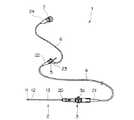
図1及び図2は本発明の一実施形態に係り、図1は内視鏡の構成を説明する斜視図、図2は折れ止めによって覆われている部分における可撓管の構成を示す断面図である。
【0012】
図1に示すように本実施形態の内視鏡1は、体腔内に挿入される細長で柔軟性を有する挿入部2と、この挿入部2の基端側に設けられる操作部3と、この操作部3の外周面に一端を連結した細長で柔軟な少なくともライトガイドファイバーを内挿するユニバーサルケーブル4と、このユニバーサルケーブル4の他端に設けられ、図示しない光源装置に着脱自在な光源用コネクタ5と、この光源用コネクタ5から分岐する細長で柔軟な電気信号を伝送する信号線を挿通するカメラケーブル6と、このカメラケーブル6の端部に設けられ、図示しないカメラコントロールユニットに着脱自在なカメラコネクタ7とで主に構成されている。
【0013】
前記挿入部2は、先端側から順に、硬質部材で形成した先端硬質部11、複数の湾曲コマを連接して例えば上下方向に湾曲動作する湾曲部12、柔軟な軟性部材で形成した可撓管である可撓管部13を連接して構成されている。
【0014】
前記可撓管13の、前記操作部3を構成する本体部材に連結固定される、基端部には、連結部分を保護する弾性を有する部材で形成された折れ止め20が被せられている。また、前記ユニバーサルケーブル4の操作部3及び光源用コネクタ5との連結部である両端部にもそれぞれ折れ止め21,22が被せられており、前記カメラケーブル6の光源用コネクタ5及びカメラコネクタ7との連結部である両端部にも折れ止め23,24が被せられている。
【0015】
なお、前記操作部3には前記湾曲部12を所望の方向に湾曲させるための操作レバー3aが設けられており、この操作レバー3aを操作することによって、前記湾曲部12の先端に配置されている図示しない湾曲駒に連結されている操作ワイヤを牽引して湾曲部12を湾曲させ、先端硬質部11の先端面を所望の方向に向けることができるようになっている。
【0016】
図2に示すように前記可撓管部13は、内周側から順にステンレスなど金属製の弾性帯状板をスパイラル状に巻いて形成した螺旋管15と、この螺旋管15の外側に配置されたステンレス線又はタングステン線などの金属線を編組して形成した網状管16と、この網状管16の外側に被着される柔軟なエラストマーからなる外皮17とで構成されている。
【0017】
前記折れ止め21は、例えばゴム部材で形成されており、外皮14の外表面を締め付けるように配置される。すなわち、前記折れ止め21の先端部分の内径寸法は、前記可撓管部13基端部の外径寸法よりも小さく設定してあるので、折れ止め21の締め付け力によって内周面が前記外皮14の外表面に密着した状態になっている。このため、この折れ止め21の外部に触れた流体が、前記外皮14の外周面と折れ止め21の内周面との間から侵入することを防止している。
【0018】
この折れ止め20によって被われている可撓管部13には、この可撓管部13の内部空間である内孔13aと、可撓管部13外部とを連通する少なくとも1つの貫通穴である通気孔18が形成してある。この通気孔18は、前記網状管16及び外皮17を貫通しており、この通気孔18の外部側開口は前記折れ止め20によって塞がれている。
【0019】
なお、前記ユニバーサルケーブル4に設けられる折れ止め21,22及び前記カメラケーブル6に設けられる折れ止め23,24も前記折れ止め20と同様に構成されている。
【0020】
また、前記可撓管部13の内部空間に操作部3の内部空間介して連通する内部空間を有するユニバーサルケーブル4の折れ止め21,22によって覆われる両端部や、前記ユニバーサルケーブル4の内部空間に光源用コネクタ5の内部空間を介して連通する内部空間を有するカメラケーブル6の折れ止め23,24によって覆われる両端部にはそれぞれ上述した通気孔18と同様の通気孔が形成してある。
【0021】
上述のように構成した内視鏡1の作用を説明する。
使用後の内視鏡1を高圧蒸気滅菌をするため、例えば高温下、或いは、陰圧下に曝すと内視鏡1の内部空間の空気が膨張していく。このとき、内視鏡1の内部空間の空気がある一定量まで膨張すると、内部の空気は通気孔18を通って弾性を有する部材で形成されている折れ止め20を押圧する。すると、この折れ止め20の内周面と可撓管部13の外周面との間に隙間が形成され、この隙間を通って空気が外部に漏れ出て、一定の膨張状態に保持される。
【0022】
なお、通気孔の開口は、内部空間の空気が膨張していない通常状態では折れ止めの内周面が密着して塞がれているので、内視鏡を薬液などの流体中に浸漬させた場合でも内部に流体等が侵入しない。
【0023】
このように、可撓管の、弾性を有する折れ止めによって覆われる部分に、この可撓管の内部空間と外部とを連通する通気孔を形成したことにより、高圧蒸気滅菌時等、内視鏡が高温下、或いは、陰圧下に曝されて内部空間の空気が膨張したとき、この膨張した空気によって押し広げられて形成される折れ止めと可撓管との隙間から空気が漏れ出て可撓管の外皮が破裂することを防止することができる。
【0024】
なお、前記内視鏡が操作部に接眼部を設けた、いわゆる光学式内視鏡の場合には前記カメラケーブルは不要であり、前記光源用コネクタの側部には前記カメラケーブルは備えられていない。
【0025】
また、前記可撓管部13の外皮17を耐熱性を有するシリコン系樹脂で形成する場合、このシリコン系樹脂で形成した外皮の内径寸法を、組立上、網状管の外径寸法より小さく設定することができない。このため、外皮17の網状管16に対する締め付け力量が小さくなってしまい、このことにより、この外皮17が網状管いるゆるに対して軸方向や周方向に位置ずれするおそれがある。これを防止するため、図3に示すように網状管16の外周面に対して外皮17の締め付け力量を増大させるための突起部40を1つ以上形成している。
【0026】
この突起部40としては、例えば図に示すリング状部材41を半田や接着剤などの固定部材42で固定したものである。前記リング状部材41は、内径寸法を前記網状管16の外径寸法と略同一に形成してある。なお、前記突起部40を形成する部材は前記リング状部材41に限定されるものではなく、網状管16の外周面より突出する突起部40を形成するように構成されるものであればよい。
【0027】
このことにより、耐熱性を有するシリコン系樹脂で形成した外皮が網状管に対して軸方向や周方向に位置ずれすることが防止されるとともに、オートクレーブ滅菌時に内視鏡が高温下に曝された際外皮が熱によって劣化することが防止される。
【0028】
ところで、従来の内視鏡では、湾曲部を湾曲操作する操作レバーなどの摺動部にグリースを塗布していた。しかし、摺動部にグリースを塗布した内視鏡をオートクレーブ滅菌装置で滅菌すると、熱によってグリースが溶け出して外観が悪くなるという問題があった。また、摺動部に塗布したグリースが溶け出すことによって、摺動部の抵抗が大きくなるという問題があった。このため、オートクレーブ滅菌装置で滅菌した場合でも操作部の見栄えが悪くなったり、摺動部の摺動性が悪化することのない内視鏡が望まれていた。
【0029】
図4は操作部の操作レバーの概略構成を説明する図である。
図に示すように操作部3に設けられている操作レバー3aは、前記本体部材31に形成されている透孔31aに回動自在に配設される軸部32の一端部に螺合固定されている。この軸部32の他端部にはワイヤ33の一端部を接続固定したドラム部34が螺合固定されている。
【0030】
前記透孔31aの内周面には、例えば、フッ素樹脂、硫化化合物、カーボン、窒化化合物で形成された固体潤滑部材35が配置されている。前記フッ素樹脂は、例えばPTFEパウダーでもよい。前記硫化化合物は、例えば二硫化モリブデン、二硫化タングステンでもよい。前記カーボンは、例えば人工黒鉛でもよい。前記窒化化合物は、例えば窒化ホウ素でもよい。一方、前記軸部32の外周面には前記固体潤滑部材35と同様な固体潤滑部材36が配置されている。すなわち、前記軸部32と本体部材31とはそれぞれの部材31,32に配置した固体潤滑部材35,36を介して回動自在に構成されている。
【0031】
また、前記固体潤滑部材36を配置した軸部32の外周面にはOリング37を配するためのOリング溝32aが形成してある。このOリング溝32aに嵌め込まれたOリング37が本体部材31の透孔31aの内周面に密着することによって操作部3内部の水密を確保している。
【0032】
上述のように構成されている操作レバー3aを、本体部材31に対して回動させると、この操作レバー3aの操作に追従して軸部32及びドラム部34が回動してワイヤ33が牽引され、前記湾曲部12が湾曲動作する。このとき、透孔31aの内周面及び軸部32の外周面に固体潤滑部材35,36が設けられているので、本体部材31と軸部32との間の摺動抵抗は小さい。また、内視鏡を高温下に曝したばあいでも固体潤滑部材35,36が溶けることはない。
【0033】
このように、摺動部にグリースを塗布する代わりに、固体潤滑部材を配置したことにより、高圧蒸気滅菌の際に、グリースが溶け出して発生する、外観の不具合や摺動性の低下を防止することができる。
【0034】
なお、本発明は、以上述べた実施形態のみに限定されるものではなく、発明の要旨を逸脱しない範囲で種々変形実施可能である。
【0035】
[付記]
以上詳述したような本発明の上記実施形態によれば、以下の如き構成を得ることができる。
【0036】
(1)可撓管と、この可撓管と他部材との連結部に設けた弾性を有する折れ止めとを備えた内視鏡において、
前記可撓管の、前記折れ止めによって被われる部分に、この可撓管の内部空間と外部とを連通する少なくとも1つの貫通穴を有する内視鏡。
【0037】
(2)前記可撓管は、内視鏡の挿入部を構成する可撓管部である付記1記載の内視鏡。
【0038】
(3)前記可撓管は、内部に少なくともライトガイドファイバーが挿通するユニバーサルケーブルである付記1記載の内視鏡。
【0039】
(4)前記可撓管は、内部に電気信号を伝送する信号線が挿通するカメラケーブルである付記1記載の内視鏡。
【0040】
【発明の効果】
以上説明したように本発明によれば、高圧蒸気滅菌時等、内視鏡が高温下、或いは、陰圧下に曝された際、圧力に対して弱い部材が破裂することを防止した可撓管を有する内視鏡を提供することできる。
【図面の簡単な説明】
【図1】図1及び図2は本発明の一実施形態に係り、図1は
内視鏡の構成を説明する斜視図
【図2】折れ止めによって覆われている部分における可撓管の構成を示す断面図
【図3】シリコン系樹脂で形成した外皮に対する網状管の構成例を示す図
【図4】操作部の操作レバーの概略構成を説明する図
【符号の説明】
13…可撓管部
13a…内孔
15…螺旋管
16…網状管
17…外皮
18…通気孔
20…折れ止め[0001]
BACKGROUND OF THE INVENTION
The present invention relates to an endoscope having a flexible insertion portion for performing sterilization after use with an autoclave device.
[0002]
[Prior art]
Endoscopes used in the medical field include various types of treatments by inserting an endoscope insertion portion into a body cavity and observing an organ or the like or using a treatment tool inserted into a treatment tool channel of an endoscope. Or take action. Therefore, when an endoscope or treatment tool that has been used once is reused for other patients, it is necessary to prevent infection between patients via the endoscope and treatment tool. Had to be done.
[0003]
Gases such as ethylene oxide gas (EOG) and a disinfectant solution have been used for disinfecting and sterilizing these endoscopes and their accessories. However, as is well known, sterilization gases are extremely toxic and there is a problem that the work process becomes complicated in order to ensure the safety of sterilization work. Moreover, since it takes time to aerate to remove the gas adhering to the device after sterilization, the device cannot be used immediately after sterilization. Furthermore, there is a problem that the running cost becomes expensive.
[0004]
On the other hand, in the case of a disinfecting solution, there is a problem that management of the disinfecting agent solution is complicated and it takes a lot of money to dispose of the disinfecting solution.
[0005]
In recent years, autoclave sterilization (high-pressure steam sterilization) that can be used immediately after sterilization without complicated work and has low running cost is becoming the mainstream of disinfection sterilization processing of endoscope devices.
[0006]
This autoclave sterilization is also called general sterilization, and is evacuated before the sterilization process, sterilized in detail with high-temperature steam in a short time, and evacuated for drying after completion of the sterilization process. 1992 stipulates that the sterilization process involves exposure to about 2 atm and 132 ° C. for 4 minutes.
[0007]
[Problems to be solved by the invention]
However, in endoscopes that ensure airtightness and general watertightness, when the endoscope body is exposed to high pressure or negative pressure, the inside of the endoscope main body is at a positive pressure. There is a possibility that the outer shell, which is a member that is weak against internal pressure as compared with other members constituting the flexible tube, bursts. This is because, as shown in Japanese Utility Model Publication No. 5-19043, the flexible tube is a spiral tube in which an elastic band plate is spirally wound, a mesh tube provided outside the spiral tube, and the mesh tube. It is because it is comprised with the outer_layer | skin | deposited covering the outer periphery of this.
[0008]
The present invention has been made in view of the above circumstances, and prevents a member weak against pressure from bursting when the endoscope is exposed to high temperature or negative pressure, such as during high-pressure steam sterilization. An object of the present invention is to provide an endoscope having a flexible tube.
[0009]
[Means for Solving the Problems]
The endoscope of the present invention is an endoscope provided with a flexible flexible tube and an elastic folding stop provided at a connecting portion between the flexible tube and another member,
The flexible tube has at least one through-hole communicating with the interior space of the flexible tube and the outside at a portion covered by the bend.
[0010]
According to this configuration, when the endoscope is exposed to high temperature or negative pressure for high-pressure steam sterilization, for example, when the air inside the endoscope expands to a certain amount, It acts to push and spread the folding stopper through the through hole of the flexible tube located on the inner peripheral surface side of the folding stopper. Then, air leaks to the outside through a gap formed between the inner peripheral surface of the fold prevention and the outer peripheral surface of the flexible tube.
[0011]
DETAILED DESCRIPTION OF THE INVENTION
Embodiments of the present invention will be described below with reference to the drawings.
1 and 2 relate to an embodiment of the present invention, FIG. 1 is a perspective view illustrating the configuration of an endoscope, and FIG. 2 is a cross-sectional view illustrating the configuration of a flexible tube in a portion covered with a bend. It is.
[0012]
As shown in FIG. 1, an endoscope 1 according to this embodiment includes an elongated and
[0013]
The
[0014]
The base end portion of the
[0015]
The
[0016]
As shown in FIG. 2, the
[0017]
The
[0018]
The
[0019]
The
[0020]
Further, both ends of the
[0021]
The operation of the endoscope 1 configured as described above will be described.
In order to sterilize the endoscope 1 after use with high-pressure steam, for example, when the endoscope 1 is exposed to high temperature or negative pressure, the air in the internal space of the endoscope 1 expands. At this time, when the air in the internal space of the endoscope 1 expands to a certain amount, the internal air passes through the
[0022]
In addition, the opening of the vent hole is closed in the normal state where the air in the internal space is not expanded, so that the inner peripheral surface of the anti-bending is tightly closed, so that the endoscope is immersed in a fluid such as a chemical solution. Even in this case, fluid does not enter the inside.
[0023]
In this way, by forming a vent hole communicating the internal space of the flexible tube with the outside in the portion of the flexible tube that is covered by the elastic folding stopper, the endoscope can be used during high-pressure steam sterilization. When the air in the internal space expands due to exposure to high temperature or negative pressure, the air leaks from the gap between the crease formed by the expanded air and the flexible tube and is flexible. It is possible to prevent the outer shell of the tube from rupturing.
[0024]
In the case of a so-called optical endoscope in which the endoscope is provided with an eyepiece in the operation unit, the camera cable is not necessary, and the camera cable is provided on the side of the light source connector. Not.
[0025]
Further, when the
[0026]
As this
[0027]
As a result, the outer sheath made of heat-resistant silicone resin is prevented from being displaced in the axial direction or circumferential direction with respect to the mesh tube, and the endoscope is exposed to high temperatures during autoclave sterilization. The outer skin is prevented from being deteriorated by heat.
[0028]
By the way, in a conventional endoscope, grease is applied to a sliding portion such as an operation lever for bending the bending portion. However, when an endoscope having grease applied to the sliding portion is sterilized with an autoclave sterilizer, the grease is melted by heat and the appearance is deteriorated. In addition, there is a problem that the resistance of the sliding portion increases as the grease applied to the sliding portion melts. For this reason, even when sterilized by an autoclave sterilizer, an endoscope that does not deteriorate the appearance of the operation unit or deteriorate the sliding property of the sliding unit has been desired.
[0029]
FIG. 4 is a diagram illustrating a schematic configuration of the operation lever of the operation unit.
As shown in the figure, the operating
[0030]
A
[0031]
An O-ring groove 32a for arranging an O-ring 37 is formed on the outer peripheral surface of the
[0032]
When the
[0033]
In this way, instead of applying grease to the sliding part, a solid lubricating member is arranged to prevent appearance defects and sliding deterioration that occur when the grease melts during high-pressure steam sterilization. can do.
[0034]
It should be noted that the present invention is not limited to the embodiments described above, and various modifications can be made without departing from the spirit of the invention.
[0035]
[Appendix]
According to the embodiment of the present invention as described above in detail, the following configuration can be obtained.
[0036]
(1) In an endoscope provided with a flexible tube and an elastic folding stop provided at a connecting portion between the flexible tube and another member,
The endoscope which has at least 1 through-hole which connects the internal space and the exterior of this flexible tube in the part covered by the said bending prevention of the said flexible tube.
[0037]
(2) The endoscope according to appendix 1, wherein the flexible tube is a flexible tube portion that constitutes an insertion portion of the endoscope.
[0038]
(3) The endoscope according to appendix 1, wherein the flexible tube is a universal cable through which at least a light guide fiber is inserted.
[0039]
(4) The endoscope according to appendix 1, wherein the flexible tube is a camera cable through which a signal line for transmitting an electric signal is inserted.
[0040]
【The invention's effect】
As described above, according to the present invention, a flexible tube that prevents a member weak against pressure from bursting when the endoscope is exposed to high temperature or negative pressure, such as during high-pressure steam sterilization. Can be provided.
[Brief description of the drawings]
FIG. 1 and FIG. 2 relate to an embodiment of the present invention, and FIG. 1 is a perspective view for explaining a configuration of an endoscope. FIG. 2 shows a configuration of a flexible tube in a portion covered with a bend stopper. FIG. 3 is a diagram showing a configuration example of a mesh tube with respect to an outer skin formed of a silicon-based resin. FIG. 4 is a diagram explaining a schematic configuration of an operation lever of an operation unit.
13 ...
Claims (1)
Translated fromJapanese前記可撓管は、前記折れ止めによって被われる部分に、この可撓管の内部空間と外部とを連通する少なくとも1つの貫通穴を有することを特徴とする内視鏡。In an endoscope provided with a flexible flexible tube and an elastic folding stop provided at a connecting portion between the flexible tube and another member,
The endoscope, wherein the flexible tube has at least one through hole that communicates the internal space of the flexible tube with the outside in a portion covered with the bend.
Priority Applications (1)
| Application Number | Priority Date | Filing Date | Title |
|---|---|---|---|
| JP28964498AJP4197781B2 (en) | 1998-10-12 | 1998-10-12 | Endoscope |
Applications Claiming Priority (1)
| Application Number | Priority Date | Filing Date | Title |
|---|---|---|---|
| JP28964498AJP4197781B2 (en) | 1998-10-12 | 1998-10-12 | Endoscope |
Publications (2)
| Publication Number | Publication Date |
|---|---|
| JP2000116594A JP2000116594A (en) | 2000-04-25 |
| JP4197781B2true JP4197781B2 (en) | 2008-12-17 |
Family
ID=17745918
Family Applications (1)
| Application Number | Title | Priority Date | Filing Date |
|---|---|---|---|
| JP28964498AExpired - Fee RelatedJP4197781B2 (en) | 1998-10-12 | 1998-10-12 | Endoscope |
Country Status (1)
| Country | Link |
|---|---|
| JP (1) | JP4197781B2 (en) |
Cited By (1)
| Publication number | Priority date | Publication date | Assignee | Title |
|---|---|---|---|---|
| US7727678B2 (en) | 2000-08-11 | 2010-06-01 | Tesa Scribos Gmbh | Holographic data memory |
Families Citing this family (6)
| Publication number | Priority date | Publication date | Assignee | Title |
|---|---|---|---|---|
| JP3607860B2 (en)* | 2000-08-21 | 2005-01-05 | オリンパス株式会社 | Endoscope |
| JP2003000527A (en)* | 2001-06-21 | 2003-01-07 | Pentax Corp | Endoscope related products |
| JP2003010104A (en)* | 2001-06-27 | 2003-01-14 | Pentax Corp | Folding of flexible endoscope |
| JP4756792B2 (en)* | 2001-08-28 | 2011-08-24 | オリンパス株式会社 | Endoscope |
| US8500628B2 (en)* | 2006-02-28 | 2013-08-06 | Olympus Endo Technology America, Inc. | Rotate-to-advance catheterization system |
| EP3478150B1 (en)* | 2017-09-20 | 2022-12-28 | Bio-Medical Engineering (HK) Limited | Endoscopic system |
- 1998
- 1998-10-12JPJP28964498Apatent/JP4197781B2/ennot_activeExpired - Fee Related
Cited By (1)
| Publication number | Priority date | Publication date | Assignee | Title |
|---|---|---|---|---|
| US7727678B2 (en) | 2000-08-11 | 2010-06-01 | Tesa Scribos Gmbh | Holographic data memory |
Also Published As
| Publication number | Publication date |
|---|---|
| JP2000116594A (en) | 2000-04-25 |
Similar Documents
| Publication | Publication Date | Title |
|---|---|---|
| CN100558285C (en) | Endoscope insertion portion, endoscope, and endoscope system | |
| US20040111010A1 (en) | Flexible tube of endoscope and endoscope | |
| US8162825B2 (en) | Endoscope | |
| JPS5844033A (en) | Adaptor type treating tool introducing apparatus for endoscope | |
| US20100145150A1 (en) | Endoscope flexible portion and endoscope | |
| JP4061011B2 (en) | Endoscope | |
| JP4197781B2 (en) | Endoscope | |
| JP4418096B2 (en) | Endoscope | |
| JP2002017658A (en) | Endoscope | |
| JP2000107121A (en) | Endoscope | |
| JPH05337081A (en) | Endoscope sterilizing case | |
| JP4242484B2 (en) | Endoscope | |
| JPH0561605B2 (en) | ||
| JP2000166859A (en) | Endoscope | |
| JP2001037706A (en) | Endoscope | |
| JP4009510B2 (en) | Endoscope check valve cap and endoscope equipped with the endoscope check valve cap | |
| JP2005013321A (en) | Endoscope and method for manufacturing insulation structure of insertion part thereof | |
| JPS6111085B2 (en) | ||
| JP2008100077A (en) | Endoscope | |
| JPH11244219A (en) | Endoscope bend protection device | |
| JP2002000553A (en) | Endoscope | |
| JP2004254823A (en) | Endoscope with mantle sheath | |
| JP3717717B2 (en) | Endoscope | |
| JPS5986022A (en) | Sheath tube for endoscope | |
| JPH11318816A (en) | Endoscope |
Legal Events
| Date | Code | Title | Description |
|---|---|---|---|
| A621 | Written request for application examination | Free format text:JAPANESE INTERMEDIATE CODE: A621 Effective date:20050824 | |
| A977 | Report on retrieval | Free format text:JAPANESE INTERMEDIATE CODE: A971007 Effective date:20080904 | |
| TRDD | Decision of grant or rejection written | ||
| A01 | Written decision to grant a patent or to grant a registration (utility model) | Free format text:JAPANESE INTERMEDIATE CODE: A01 Effective date:20080916 | |
| A01 | Written decision to grant a patent or to grant a registration (utility model) | Free format text:JAPANESE INTERMEDIATE CODE: A01 | |
| A61 | First payment of annual fees (during grant procedure) | Free format text:JAPANESE INTERMEDIATE CODE: A61 Effective date:20080930 | |
| FPAY | Renewal fee payment (event date is renewal date of database) | Free format text:PAYMENT UNTIL: 20111010 Year of fee payment:3 | |
| FPAY | Renewal fee payment (event date is renewal date of database) | Free format text:PAYMENT UNTIL: 20111010 Year of fee payment:3 | |
| FPAY | Renewal fee payment (event date is renewal date of database) | Free format text:PAYMENT UNTIL: 20111010 Year of fee payment:3 | |
| FPAY | Renewal fee payment (event date is renewal date of database) | Free format text:PAYMENT UNTIL: 20121010 Year of fee payment:4 | |
| FPAY | Renewal fee payment (event date is renewal date of database) | Free format text:PAYMENT UNTIL: 20131010 Year of fee payment:5 | |
| LAPS | Cancellation because of no payment of annual fees |