JP4197129B2 - Work transfer device - Google Patents
Work transfer deviceDownload PDFInfo
- Publication number
- JP4197129B2 JP4197129B2JP2003075948AJP2003075948AJP4197129B2JP 4197129 B2JP4197129 B2JP 4197129B2JP 2003075948 AJP2003075948 AJP 2003075948AJP 2003075948 AJP2003075948 AJP 2003075948AJP 4197129 B2JP4197129 B2JP 4197129B2
- Authority
- JP
- Japan
- Prior art keywords
- workpiece
- transfer
- stage
- suction
- conveyance
- Prior art date
- Legal status (The legal status is an assumption and is not a legal conclusion. Google has not performed a legal analysis and makes no representation as to the accuracy of the status listed.)
- Expired - Fee Related
Links
Images


Classifications
- B—PERFORMING OPERATIONS; TRANSPORTING
- B65—CONVEYING; PACKING; STORING; HANDLING THIN OR FILAMENTARY MATERIAL
- B65G—TRANSPORT OR STORAGE DEVICES, e.g. CONVEYORS FOR LOADING OR TIPPING, SHOP CONVEYOR SYSTEMS OR PNEUMATIC TUBE CONVEYORS
- B65G49/00—Conveying systems characterised by their application for specified purposes not otherwise provided for
- B65G49/05—Conveying systems characterised by their application for specified purposes not otherwise provided for for fragile or damageable materials or articles
- B65G49/06—Conveying systems characterised by their application for specified purposes not otherwise provided for for fragile or damageable materials or articles for fragile sheets, e.g. glass
- B65G49/063—Transporting devices for sheet glass
- B65G49/064—Transporting devices for sheet glass in a horizontal position
- B65G49/065—Transporting devices for sheet glass in a horizontal position supported partially or completely on fluid cushions, e.g. a gas cushion
- B—PERFORMING OPERATIONS; TRANSPORTING
- B65—CONVEYING; PACKING; STORING; HANDLING THIN OR FILAMENTARY MATERIAL
- B65G—TRANSPORT OR STORAGE DEVICES, e.g. CONVEYORS FOR LOADING OR TIPPING, SHOP CONVEYOR SYSTEMS OR PNEUMATIC TUBE CONVEYORS
- B65G47/00—Article or material-handling devices associated with conveyors; Methods employing such devices
- B65G47/22—Devices influencing the relative position or the attitude of articles during transit by conveyors
- B65G47/24—Devices influencing the relative position or the attitude of articles during transit by conveyors orientating the articles
- B65G47/248—Devices influencing the relative position or the attitude of articles during transit by conveyors orientating the articles by turning over or inverting them
- B65G47/252—Devices influencing the relative position or the attitude of articles during transit by conveyors orientating the articles by turning over or inverting them about an axis substantially perpendicular to the conveying direction
- B—PERFORMING OPERATIONS; TRANSPORTING
- B65—CONVEYING; PACKING; STORING; HANDLING THIN OR FILAMENTARY MATERIAL
- B65G—TRANSPORT OR STORAGE DEVICES, e.g. CONVEYORS FOR LOADING OR TIPPING, SHOP CONVEYOR SYSTEMS OR PNEUMATIC TUBE CONVEYORS
- B65G49/00—Conveying systems characterised by their application for specified purposes not otherwise provided for
- B65G49/05—Conveying systems characterised by their application for specified purposes not otherwise provided for for fragile or damageable materials or articles
- B65G49/06—Conveying systems characterised by their application for specified purposes not otherwise provided for for fragile or damageable materials or articles for fragile sheets, e.g. glass
- B65G49/061—Lifting, gripping, or carrying means, for one or more sheets forming independent means of transport, e.g. suction cups, transport frames
- B—PERFORMING OPERATIONS; TRANSPORTING
- B65—CONVEYING; PACKING; STORING; HANDLING THIN OR FILAMENTARY MATERIAL
- B65G—TRANSPORT OR STORAGE DEVICES, e.g. CONVEYORS FOR LOADING OR TIPPING, SHOP CONVEYOR SYSTEMS OR PNEUMATIC TUBE CONVEYORS
- B65G49/00—Conveying systems characterised by their application for specified purposes not otherwise provided for
- B65G49/05—Conveying systems characterised by their application for specified purposes not otherwise provided for for fragile or damageable materials or articles
- B65G49/06—Conveying systems characterised by their application for specified purposes not otherwise provided for for fragile or damageable materials or articles for fragile sheets, e.g. glass
- B65G49/067—Sheet handling, means, e.g. manipulators, devices for turning or tilting sheet glass
- H—ELECTRICITY
- H01—ELECTRIC ELEMENTS
- H01L—SEMICONDUCTOR DEVICES NOT COVERED BY CLASS H10
- H01L21/00—Processes or apparatus adapted for the manufacture or treatment of semiconductor or solid state devices or of parts thereof
- H01L21/67—Apparatus specially adapted for handling semiconductor or electric solid state devices during manufacture or treatment thereof; Apparatus specially adapted for handling wafers during manufacture or treatment of semiconductor or electric solid state devices or components ; Apparatus not specifically provided for elsewhere
- H01L21/677—Apparatus specially adapted for handling semiconductor or electric solid state devices during manufacture or treatment thereof; Apparatus specially adapted for handling wafers during manufacture or treatment of semiconductor or electric solid state devices or components ; Apparatus not specifically provided for elsewhere for conveying, e.g. between different workstations
- H01L21/67784—Apparatus specially adapted for handling semiconductor or electric solid state devices during manufacture or treatment thereof; Apparatus specially adapted for handling wafers during manufacture or treatment of semiconductor or electric solid state devices or components ; Apparatus not specifically provided for elsewhere for conveying, e.g. between different workstations using air tracks
- H—ELECTRICITY
- H01—ELECTRIC ELEMENTS
- H01L—SEMICONDUCTOR DEVICES NOT COVERED BY CLASS H10
- H01L21/00—Processes or apparatus adapted for the manufacture or treatment of semiconductor or solid state devices or of parts thereof
- H01L21/67—Apparatus specially adapted for handling semiconductor or electric solid state devices during manufacture or treatment thereof; Apparatus specially adapted for handling wafers during manufacture or treatment of semiconductor or electric solid state devices or components ; Apparatus not specifically provided for elsewhere
- H01L21/683—Apparatus specially adapted for handling semiconductor or electric solid state devices during manufacture or treatment thereof; Apparatus specially adapted for handling wafers during manufacture or treatment of semiconductor or electric solid state devices or components ; Apparatus not specifically provided for elsewhere for supporting or gripping
- H01L21/6838—Apparatus specially adapted for handling semiconductor or electric solid state devices during manufacture or treatment thereof; Apparatus specially adapted for handling wafers during manufacture or treatment of semiconductor or electric solid state devices or components ; Apparatus not specifically provided for elsewhere for supporting or gripping with gripping and holding devices using a vacuum; Bernoulli devices
- B—PERFORMING OPERATIONS; TRANSPORTING
- B65—CONVEYING; PACKING; STORING; HANDLING THIN OR FILAMENTARY MATERIAL
- B65G—TRANSPORT OR STORAGE DEVICES, e.g. CONVEYORS FOR LOADING OR TIPPING, SHOP CONVEYOR SYSTEMS OR PNEUMATIC TUBE CONVEYORS
- B65G2249/00—Aspects relating to conveying systems for the manufacture of fragile sheets
- B65G2249/04—Arrangements of vacuum systems or suction cups
- B65G2249/045—Details of suction cups suction cups
Landscapes
- Engineering & Computer Science (AREA)
- Physics & Mathematics (AREA)
- Condensed Matter Physics & Semiconductors (AREA)
- General Physics & Mathematics (AREA)
- Manufacturing & Machinery (AREA)
- Computer Hardware Design (AREA)
- Microelectronics & Electronic Packaging (AREA)
- Power Engineering (AREA)
- Mechanical Engineering (AREA)
- Container, Conveyance, Adherence, Positioning, Of Wafer (AREA)
- Attitude Control For Articles On Conveyors (AREA)
Description
Translated fromJapanese【0001】
【発明の属する技術分野】
本発明は、半導体、液晶表示素子やELやPDPをはじめとするフラットパネルディスプレイや、太陽電池パネル等を製造する際にガラス基板や半導体ウエハなどのワークを搬送するワーク搬送装置に関し、特に、ワークの裏面処理、或いは両面処理を行うためにワークを円滑に表裏反転させる対策に係わる。
【0002】
【従来の技術】
従来、半導体、フラットパネルディスプレイ、太陽電池等の製造現場では、ガラス基板や半導体ウエハ(以下、まとめてワークと称する)の洗浄やフォトなどの工程において、ワークの表裏を反転させる必要性が生じた場合には、メカチャック、真空チャック、静電チャックなどのチャック機構を用いてワークの端部を支持したり、ワークの裏面を吸着したりした状態で、ワークを反転させていた。
【0003】
このようなワーク搬送装置としては、図20および図21に示すように、ワークaを4つの搬送位置P1〜P4(搬送位置P1は塗布液塗布後の位置、P2はワーク側面洗浄処理位置、P3は待機位置、P4は後工程位置)に搬送し、搬送位置P1からP2への搬送時にワークaを表裏反転させて搬送するようにしたものがある(例えば、特許文献1参照)。そして、ワークaの表裏反転は、ワークaの周囲を複数個のメカチャック手段b,…のチャックコマcにより所定位置でチャックした状態で、メカチャック手段bの駆動部dを構成している図示しないモータを駆動源として、矢印e方向へ回転駆動することにより行われる。この各チャック手段bのチャックコマによるワークaのチャック動作は、エアシリンダfによる直接駆動によってスライド動作するスライドシャフトgを介して行われる。この場合、ワークの各搬送位置P1〜P4間の受け渡しは、図示しない別のロボットにより行われる。
【0004】
【特許文献1】
特開平10−264071号公報
【0005】
【発明が解決しようとする課題】
しかし、上記従来のワーク搬送装置では、ワークaが複数個のメカチャック手段b,…のチャックコマcによりチャックされているため、ワークの大型化に伴いワークに反りが発生すると、チャックの信頼性が低いものとなる。そのため、搬送、表裏反転時のワーク落下や破損、割れ欠け等の問題が発生し易い。しかも、最初からワークに反りがあると、チャックが益々困難となる。
【0006】
また、チャック動作がスライドシャフトgを介して行われるため、スライドシャフトや摺動部、回転駆動部からのパーティクル発生が懸念される。しかも、メカニカル部品が多く装置構成が複雑であるため、故障し易くメンテナンス時の労力も大きい上、装置サイズが大きなものとなる。
【0007】
更に、メカチャックの代わりに真空チャックや静電チャックを用いた場合においても、静電気の発生によってワークやプロセスに影響を与えるおそれもある。
【0008】
本発明は、かかる点に鑑みてなされたものであり、その目的とするところは、搬送、表裏反転時にワーク落下や破損、割れ欠け等を発生させることなく確実にワークを反転させることができ、メカニカル部品を最小限に抑えてメンテナンスの簡単化および装置のコンパクト化を図り、かつ静電気によるワークやプロセスへの悪影響を確実に防止することができるワーク搬送装置を提供することにある。
【0009】
【課題を解決するための手段】
上記目的を達成するため、本発明では、流体の噴出もしくは噴出と吸引との同時動作によりワークを浮上させて搬送する一対の搬送ステージを互いに上下方向に対向させて配置し、上記一対の搬送ステージのうちの少なくとも一方の搬送ステージ上にワークの周囲を保持する昇降自在な複数の昇降ピンを設けるとともに、上記一対の搬送ステージを上下反転可能に回転させる回転機構を設ける。そして、上記回転機構により上下反転された上側の搬送ステージでの上記各昇降ピンの下降に伴って上側の搬送ステージ上から下側の搬送ステージ上にワークを受け渡すようにしている。
【0010】
この特定事項により、流体の噴出もしくは噴出と吸引との同時動作により一方の搬送ステージ上に浮上しているワークは、昇降ピンを上昇させることにより周囲が保持された状態で、回転機構により回転させて一対の搬送ステージを上下反転させてから各昇降ピンを下降させると、その下降に伴って、上側にある一方の搬送ステージ上から下側にある他方の搬送ステージ上に該他方の搬送ステージでの流体の噴出もしくは噴出と吸引との同時動作により浮上した状態で受け渡される。これにより、ワークの大型化に伴いワークに反りが発生していたり最初から反りが発生していても、流体の噴出もしくは噴出と吸引との同時動作により一方の搬送ステージ上に浮上しているワークの周囲が昇降ピンの上昇により保持された状態で円滑に表裏反転されてから上側の搬送ステージでの各昇降ピンの下降に伴って上側の搬送ステージ上から下側の搬送ステージ上に浮上した状態で受け渡され、搬送、表裏反転時のワークの落下や破損、割れ欠け等を確実に防止することが可能となる。
【0011】
また、ワークのチャック動作が昇降ピンによるシンプルな昇降動作のみにより行われ、その周囲からのパーティクル発生が最小限に抑えられる。しかも、メカニカル部品を減らして、故障もし難くメンテナンス時の労力も軽減される上、装置サイズも非常にコンパクトなものとなる。
【0012】
更に、真空チャックや静電チャックを用いたもののように、静電気の発生によってワークやプロセスに悪影響を与えることもない。
【0013】
また、その他の手法としては、流体の噴出もしくは噴出と吸引との同時動作によりワークを浮上させて搬送する搬送ステージをワークの搬送方向に互いに対向させるように配置し、上記各搬送ステージ上に、ワークの周囲を保持する昇降自在な複数の昇降ピンを設けるとともに、この各昇降ピンのうちのワーク搬送方向上流側の搬送ステージのワーク搬送方向下流側に対応する昇降ピンおよびワーク搬送方向下流側の搬送ステージのワーク搬送方向上流側に対応する昇降ピンを、他の昇降ピンとは別個に昇降動作させるように制御しており、上記ワーク搬送方向上流側の搬送ステージを上下反転方向に180度未満の傾斜角度まで回転させる第1回転機構と、この第1回転機構により回転されたワーク搬送方向上流側の搬送ステージに対しワーク搬送方向に対向する傾斜角度までワーク搬送方向下流側の搬送ステージを回転させる第2回転機構とを備えている。そして、上記第1回転機構により上下反転方向に回転されたワーク搬送方向上流側の搬送ステージでのワーク搬送方向下流側の昇降ピンおよび上記第2回転機構により回転されたワーク搬送方向下流側の搬送ステージでのワーク搬送方向上流側の昇降ピンの下降動作に伴って、ワーク搬送方向上流側の搬送ステージ上からワーク搬送方向下流側の搬送ステージ上にワークを自重により滑らせて受け渡すようにしている。
【0014】
この特定事項により、流体の噴出もしくは噴出と吸引との同時動作によりワーク搬送方向上流側の搬送ステージ上に浮上しているワークは、昇降ピンを上昇させることにより周囲が保持された状態で、第1回転機構により上下反転方向に180度未満の角度まで回転させてワーク搬送方向上流側の搬送ステージを傾斜させてから、ワーク搬送方向上流側の搬送ステージでのワーク搬送方向下流側の昇降ピンおよびワーク搬送方向下流側の搬送ステージでのワーク搬送方向上流側の昇降ピンを下降させると、その下降に伴って、ワーク搬送方向上流側の搬送ステージ上からワーク搬送方向下流側の搬送ステージ上に該ワーク搬送方向下流側の搬送ステージでの流体の噴出もしくは噴出と吸引との同時動作により浮上した状態で自重により滑らせて受け渡される。これにより、ワークの大型化に伴いワークに反りが発生していたり最初から反りが発生していても、流体の噴出もしくは噴出と吸引との同時動作によりワーク搬送方向上流側の搬送ステージ上に浮上しているワークの周囲が昇降ピンの上昇により保持された状態で円滑に表裏反転されてから、ワーク搬送方向上流側の搬送ステージでのワーク搬送方向下流側の昇降ピンおよびワーク搬送方向下流側の搬送ステージでのワーク搬送方向上流側の昇降ピンの下降に伴ってワーク搬送方向上流側の搬送ステージ上からワーク搬送方向下流側の搬送ステージ上にワークを浮上させた状態で滑らせて受け渡され、搬送、表裏反転時のワークの落下や破損、割れ欠け等を確実に防止することが可能となる。
【0015】
また、ワークのチャック動作が昇降ピンによるシンプルな昇降動作のみにより行われ、その周囲からのパーティクル発生を最小限に抑えることが可能となり、メカニカル部品を最小限に抑えて故障も少なくメンテナンスの簡単化および装置のコンパクト化を図ることも可能となる。
【0016】
更に、静電気の発生によるワークやプロセスへの悪影響を確実に防止することが可能となる。
【0017】
ここで、各昇降ピンを、ゴム、ゲル、樹脂を主原料とする緩衝材または防振材により被覆している場合には、ワークを表裏反転させる際にワークの周囲が昇降ピンによってより確実に保持されることになり、搬送、表裏反転時のワークの落下や破損、割れ欠け等をより確実に防止することが可能となる。しかも、各昇降ピンによってワークの周囲を保持した際の接触によるワークの損傷を防止することも可能となる。
【0018】
更に、その他の手法としては、流体の噴出もしくは噴出と吸引との同時動作によりワークを浮上させて搬送する一対の搬送ステージを互いに上下方向に対向して配置し、この一対の搬送ステージのうちの少なくとも一方の搬送ステージに対しワークを流体の吸引により吸着させた状態で、上記一対の搬送ステージを上下反転可能に回転させる回転機構を備える。そして、上記回転機構により上下反転された上側の搬送ステージ上から流体の吸引解除に伴って下側の搬送ステージ上にワークを受け渡すようにしている。
【0019】
この特定事項により、流体の噴出もしくは噴出と吸引との同時動作により一方の搬送ステージ上に浮上しているワークは、この一方の搬送ステージに対しワークを流体の吸引により吸着させた状態で、回転機構により回転させて一対の搬送ステージを上下反転させてから、上側となった一方の搬送ステージ上から流体の吸引解除させると、その吸引解除に伴って、上側にある一方の搬送ステージ上から下側にある他方の搬送ステージ上に該他方の搬送ステージでの流体の噴出もしくは噴出と吸引との同時動作により浮上した状態で受け渡される。これにより、ワークの大型化に伴いワークに反りが発生していたり最初から反りが発生していても、流体の噴出もしくは噴出と吸引との同時動作により一方の搬送ステージ上に浮上しているワークがその一方の搬送ステージ上に流体の吸引により吸着された状態で円滑に表裏反転されてから上側となった一方の搬送ステージでの流体の吸引解除に伴って一方の搬送ステージ上から下側となる他方の搬送ステージ上に浮上した状態で受け渡され、搬送、表裏反転時のワークの落下や破損、割れ欠け等を確実に防止することが可能となる。
【0020】
また、ワークのチャック動作が流体の吸引のみにより行われ、メカニカル部品によるワークのチャック動作が不要となってパーティクル発生を可及的に抑えることが可能となり、メカニカル部品をなくしてメンテナンスの簡単化および装置のコンパクト化を図ることも可能となる。
【0021】
そして、各搬送ステージを上下方向および左右方向に移動可能に支持している場合には、ワークを表裏反転させる際に回転する搬送ステージが付近の部材と干渉することが確実に防止されることになり、ワークの表裏反転を円滑に行うことが可能となる。
【0022】
【発明の実施の形態】
(実施の形態1)
以下、本発明の実施の形態を図面に基づいて説明する。
【0023】
<第1の実施の形態>
図1ないし図3は、本発明の第1の実施形態に係わるワーク搬送装置Xを示し、1はワークWを表裏反転させるワーク回転部、2はワーク回転部1にワークWを搬入するワーク搬入部、3はワーク回転部1からワークWを搬出するワーク搬出部である。上記ワーク回転部1、ワーク搬入部2およびワーク搬出部3は、ベース台Xa上に一列に並んで配置されている。この場合、ワークWとしては、半導体、液晶表示素子やELやPDPをはじめとするフラットパネルディスプレイや、太陽電池パネル等を製造する場合のガラス基板や半導体ウエハなどの略矩形状のものが適用される。
【0024】
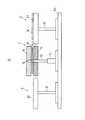
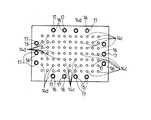
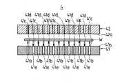
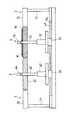
上記ワーク回転部1は、ベース台Xa上に設置された左右一対の支持脚11(図1ないし図3では紙面手前側のみ示す)と、この支持脚11に対し上下方向に伸縮動する伸縮軸12と、この伸縮軸12の先端に回転軸13を介して回転可能に支持された上下一対の第1および第2搬送ステージ14,15とを備えている。この回転軸13と、図示しないモータとによって、上下一対の第1および第2搬送ステージ14,15を回転させる回転機構が構成されている。そして、上記第1および第2搬送ステージ14,15は、互いに上下方向に対向して配置されている。この第1および第2搬送ステージ14,15の平面視で略矩形状を呈する互いの対向面14a,15aの中央付近には、図示しないガス供給用タンク或いはボンベから供給されるガスを供給通路14b,15b(図4ないし図7に表れる)を介して噴出させる複数のガス噴出口14c,15cと、この各ガス噴出口14c,15cから噴出したガスを吸引する複数のガス吸引口14d,15dとが互いに相隣ならないように交互に設けられている。また、図4ないし図7に示すように、上記各ガス噴出口14c,15cから噴出したガスは、ワークWに衝突したのち各ガス吸引口14d,15dに吸引され、吸引通路14e,15eを介して図示しない排気用ポンプ或いはブロアにより装置外へと排出される。この場合、各ガス噴出口14c,15cから噴出したガスがワークWに衝突することによってワークWに浮上力を作用させ、ワークWが浮上するようになっている。また、図4に示すように、下側に位置する第1搬送ステージ14(対向面14a)の各ガス噴出口14cから噴出したガスのみがワークWに衝突したり、図7に示すように、下側に位置する第2搬送ステージ15(対向面15a)の各ガス噴出口15cから噴出したガスのみがワークWに衝突しても、ワークWに浮上力が作用し、ワークWが浮上する。
【0025】
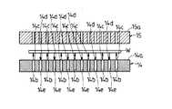
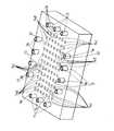
そして、図8および図9にも示すように、上記第1搬送ステージ14の対向面14aの中央付近の周り、つまり各ガス噴出口14cおよび各ガス吸引口14dの周囲には、その周方向所定間隔置きに複数の昇降自在な昇降ピン16,…が設けられている。この各昇降ピン16は、図示しないアクチュエータによって昇降動し、第1搬送ステージ14上にて浮上しているワークWの周囲を上昇時に保持するようになされている。上記各昇降ピン16の周面は、ゴム、ゲル、樹脂を主原料とする緩衝材17により被覆されている。また、上記第2搬送ステージ15の対向面15aの中央付近の周り、つまり各ガス噴出口15cおよび各ガス吸引口15dの周囲には、上記各昇降ピン16の先端を嵌入する嵌入穴(図示せず)が該各昇降ピン16に対応して凹設されている。
【0026】
また、図1ないし図3に示すように、上記ワーク搬入部2は、ベース台Xa上に設置された左右一対の支持脚21(図1ないし図3では紙面手前側のみ示す)と、この各支持脚21の先端に固定された搬入ステージ22とを備えている。一方、上記ワーク搬出部3は、ベース台Xa上に設置された左右一対の支持脚31(図1ないし図3では紙面手前側のみ示す)と、この各支持脚31の先端に固定された搬出ステージ32とを備えている。上記搬入ステージ22および搬出ステージ32にも、図示しないガス供給用タンク或いはボンベから供給されるガスを供給通路(図示せず)を介して噴出させる複数のガス噴出口(図示せず)と、この各ガス噴出口から噴出したガスを吸引する複数のガス吸引口(図示せず)とが互いに相隣ならないように交互に設けられている。そして、上記各ガス噴出口から噴出したガスは、ワークWに衝突したのち各ガス吸引口に吸引され、吸引通路(図示せず)を介して図示しない排気用ポンプ或いはブロアにより装置外へと排出される。この場合においても、各ガス噴出口から噴出したガスがワークWに衝突することによってワークWに浮上力を作用させ、ワークWが浮上するようになっている。なお、搬入ステージ22および搬出ステージ32の各ガス噴出口から噴出したガスのみをワークWに衝突させることによって、ワークWに浮上力を作用させてワークWを浮上させるようにしてもよい。
【0027】
次に、搬入ステージ22から搬入されたワークWを表裏反転させてから搬出ステージ32に搬送する手順について説明する。
【0028】
まず、図1および図4に示すように、搬入部2の搬入ステージ22において、各ガス噴出口から噴出したガスをワークWに衝突させたのち各ガス吸引口に吸引させることによって、搬入ステージ22上に浮上させていたワークWがワーク回転部1の下側の第1搬送ステージ14に搬入されると、この第1搬送ステージ14(対向面14a)において、供給通路14bを介して各ガス噴出口14cから噴出したガスをワークWに衝突させたのち各ガス吸引口14dから吸引通路14eを介して吸引させることによって、第1搬送ステージ14にてワークWが浮上した状態で受け渡される。
【0029】
次いで、図5に示すように、上側の第2搬送ステージ15(対向面15a)において、各供給通路15bを介してガス噴出口15cから噴出したガスをワークWに衝突させたのち各ガス吸引口15dから吸引通路15eを介して吸引させることによって、ワークWを第1搬送ステージ14と第2搬送ステージ15との間の中立位置に浮遊させてから、第1搬送ステージ14より各昇降ピン16を上昇させ、図6に示すように、各昇降ピン16の先端を第2搬送ステージ15の嵌入穴にそれぞれ嵌入させる。このとき、ワークWは、第1搬送ステージ14と第2搬送ステージ15との間の中立位置に浮上した状態で、各昇降ピン16の周面(緩衝材17)との接触により保持される。
【0030】
その後、図2にも示すように、回転軸13を支点にして第1および第2搬送ステージ14,15を図6の紙面時計回りに180度回転させる。このとき、回転軸13を支点として回転する第1および第2搬送ステージ14,15が、搬入ステージ22または搬出ステージ32と干渉するおそれがある場合には、伸縮軸12を伸長させることで、容易に干渉回避できることになる。
【0031】
それから、図7に示すように、第1搬送ステージ14の各昇降ピン16を下降させるとともに、第1搬送ステージ14における供給通路14bを介した各ガス噴出口14cからのガスの噴出および各ガス吸引口14dからの吸引通路14eを介したガスの吸引を停止することによって、下側となった第2搬送ステージ15での各供給通路15bを介したガス噴出口15cからのガスの噴出および各ガス吸引口15dからの吸引通路15eを介したガスの吸引により該第2搬送ステージ15上にワークWを受け渡す。
【0032】
しかる後、第2搬送ステージ15上に浮上させていたワークWを、搬出部3の搬出ステージ32上に搬送し、この搬出ステージ32上において、各ガス噴出口から噴出したガスをワークWに衝突させたのち各ガス吸引口に吸引させることによって、搬出ステージ32にてワークWが浮上した状態で受け渡される。
【0033】
このとき、第2搬送ステージ15が下側に、第1搬送ステージ14が上側にそれぞれ位置しているが、ワーク搬入部2の搬入ステージ22からの次のワークWは、第2搬送ステージ15上に搬入され、同様の手順でワークWが表裏反転されて第2搬送ステージ15から第1搬送ステージ14に受け渡されると、この第1搬送ステージ14から搬出部3の搬出ステージ32にワークWが搬送されることになる。
【0034】
このように、ガスの噴出と吸引との同時動作により第1搬送ステージ14上に浮上しているワークWは、各昇降ピン16を上昇させることにより周囲が保持された状態で、回転軸13を支点にして紙面時計回りに回転させて一対の第1および第2搬送ステージ14,15を上下反転させてから各昇降ピン16を下降させると、その下降に伴って、上側にある第1搬送ステージ14上から下側にある第2搬送ステージ15上に該第2搬送ステージ15でのガスの噴出と吸引との同時動作により浮上した状態で受け渡される。これにより、ワークWの大型化に伴いワークWに反りが発生していたり最初から反りが発生していても、ガスの噴出と吸引との同時動作により第1搬送ステージ14上に浮上しているワークWの周囲が各昇降ピン16の上昇により保持された状態で円滑に表裏反転されたのち、上側の第1搬送ステージ14での各昇降ピン16の下降に伴って該第1搬送ステージ14上から下側の第2搬送ステージ15上に浮上した状態で受け渡され、搬送、表裏反転時のワークWの落下や破損、割れ欠け等を確実に防止することができる。
【0035】
また、ワークWのチャック動作が各昇降ピン16によるシンプルな昇降動作のみにより行われ、その周囲からのパーティクル発生を最小限に抑えることができる。しかも、メカニカル部品を減らして、故障もし難くメンテナンス時の労力も軽減できる上、装置サイズも非常にコンパクトなものにすることができる。
【0036】
更に、真空チャックや静電チャックを用いたもののように、静電気の発生によってワークWやプロセスに悪影響を与えることもなく、静電気によるワークWやプロセスへの悪影響を確実に防止することができる。
【0037】
<第2の実施の形態>
次に、本発明の第2の実施形態を図10ないし図13に基づいて説明する。
【0038】
この実施形態では、第1および第2搬送ステージの構成を変更している。なお、第1および第2搬送ステージを除くその他の構成は、上記第1の実施形態の場合と同じであり、同じ部分については同一の符号を付して、その詳細な説明は省略する。
【0039】
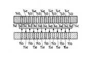
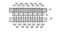
すなわち、本実施形態では、図10ないし図13に示すように、ワーク回転部4の第1および第2搬送ステージ41,42の対向面41a,42aの中央付近には、複数の供給通路41b,42bを介してガスを噴出させるガス噴出口41c,42cと、複数の吸引通路41e,42eを介してガスを吸引するガス吸引口41d,42dとが互いに相隣ならないように交互に設けられている。そして、上記第1搬送ステージ41の対向面41aの中央付近の周り、つまり各ガス噴出口41cおよび各ガス吸引口41dの周囲には、昇降ピンが存在しない構成となっている。
【0040】
次に、搬入ステージ22から搬入されたワークWを表裏反転させてから搬出ステージ32に搬送する手順について説明する。
【0041】
まず、図10に示すように、搬入部2の搬入ステージ22上に浮上させていたワークWがワーク回転部1の下側の第1搬送ステージ41に搬入されると、この第1搬送ステージ41(対向面41a)において、供給通路41bを介して各ガス噴出口41cから噴出したガスをワークWに衝突させたのち各ガス吸引口41dから吸引通路41eを介して吸引させることによって、第1搬送ステージ41にてワークWが浮上した状態で受け渡される。
【0042】
次いで、図11に示すように、各供給通路41bを介したガス噴出口41cからのガスの噴出を停止し、各ガス吸引口41dから吸引通路41eを介してガスを吸引する。
【0043】
その後、図12に示すように、各ガス吸引口41dから吸引通路41eを介したガスの吸引によって、ワークWを第1搬送ステージ41の対向面41a上に吸着させておき、この状態で、回転軸13を支点にして第1および第2搬送ステージ41,42を図12の紙面時計回りに180度回転させる。このとき、回転軸13を支点として回転する第1および第2搬送ステージ41,42が、搬入ステージ22または搬出ステージ32と干渉するおそれがある場合には、伸縮軸12を伸長させることで、容易に干渉回避できることになる。
【0044】
それから、図13に示すように、上側の第1搬送ステージ41での第1各ガス吸引口41dからの吸引通路41eを介したガスの吸引を停止させて、ワークWを自重により落下させるとともに、第2搬送ステージ42において供給通路42bを介して各ガス噴出口42cから噴出したガスをワークWに衝突させつつ各ガス吸引口42dから吸引通路42eを介して吸引させることによって、第2搬送ステージ42上にワークWが浮上した状態で受け渡される。
【0045】
しかる後、第2搬送ステージ15上に浮上させていたワークWを、搬出部3の搬出ステージ32上に搬送し、この搬出ステージ32上において、各ガス噴出口から噴出したガスをワークWに衝突させたのち各ガス吸引口に吸引させることによって、搬出ステージ32にてワークWが浮上した状態で受け渡される。
【0046】
このとき、第2搬送ステージ42が下側に、第1搬送ステージ41が上側にそれぞれ位置しているが、ワーク搬入部2の搬入ステージ22からの次のワークWは、第2搬送ステージ42上に搬入され、同様の手順でワークWが表裏反転されて第2搬送ステージ42から第1搬送ステージ41に受け渡されると、この第1搬送ステージ41から搬出部3の搬出ステージ32にワークWが搬送されることになる。
【0047】
このように、ガスの噴出と吸引との同時動作により下側の第1搬送ステージ41上に浮上しているワークWは、この第1搬送ステージ41に対しワークWをガスの吸引により吸着させた状態で、回転軸13を支点にして紙面時計回りに回転させて一対の第1および第2搬送ステージ41,42を上下反転させてから、上側となった第1搬送ステージ41上でのガスの吸引を停止させると、その吸引停止に伴い自重によって落下し、上側にある第1搬送ステージ41上から下側にある第2搬送ステージ42上に該第2搬送ステージ42でのガスの噴出と吸引との同時動作により浮上した状態で受け渡される。これにより、ワークWの大型化に伴いワークWに反りが発生していたり最初から反りが発生していても、ガスの噴出と吸引との同時動作により第1搬送ステージ41上に浮上しているワークWがその第1搬送ステージ41の対向面41a上にガスの吸引により吸着された状態で円滑に表裏反転されてから上側となった第1搬送ステージ41でのガスの吸引停止に伴い自重によって第1搬送ステージ41上から下側となる第2搬送ステージ42上に浮上した状態で受け渡され、搬送、表裏反転時のワークWの落下や破損、割れ欠け等を確実に防止することができる。
【0048】
また、ワークWのチャック動作が流体の吸引のみにより行われ、メカニカル部品によるワークのチャック動作が不要となってパーティクル発生を可及的に抑えることができ、メカニカル部品をなくしてメンテナンスの簡単化および装置のコンパクト化を図ることもできる。
【0049】
<第3の実施の形態>
次に、本発明の第3の実施形態を図14ないし図19に基づいて説明する。
【0050】
この実施形態では、ワーク回転部の構成を変更している。なお、ワーク回転部を除くその他の構成は、上記第1の実施形態の場合と同じであり、同じ部分については同一の符号を付して、その詳細な説明は省略する。
【0051】
すなわち、本実施形態では、図14および図15に示すように、ワーク搬入部2とワーク搬出部3との間には、ワーク搬送方向上流側の上流側ワーク回転部5と、ワーク搬送方向下流側の下流側ワーク回転部6とが設けられ、この上流側ワーク回転部5および下流側ワーク回転部6、ワーク搬入部2並びにワーク搬出部3は、ベース台Xa上に一列に並んで配置されている。
【0052】
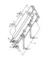
上記上流側ワーク回転部5は、ベース台Xa上に設置されたワーク搬送方向に延びる左右一対のレール49(図14および図15では紙面手前側のみ示す)のワーク搬送方向上流側(図14および図15では右側)に摺動自在に支持されたスライダ51と、このスライダ51に固着された支持脚52と、この支持脚52に対し上下方向に伸縮動する伸縮軸53と、この伸縮軸53の先端に回転軸54を介して回転可能に支持されたワーク搬送方向上流側の上流側搬送ステージ55とを備えている。この回転軸54と、図示しないモータとによって、上流側搬送ステージ55を回転軸54を支点にして上下反転方向に135°以上180°未満の傾斜角度となるまで図15に示す反時計回りで回転させる第1回転機構が構成されている。また、上記上流側搬送ステージ55は、レール49に沿ってワーク搬送方向(図14および図15では左右方向)に摺動自在に、かつ伸縮軸53によって上下方向に昇降自在に支持されている。
【0053】
一方、上記下流側ワーク回転部6は、ベース台Xa上に設置されたワーク搬送方向に延びる左右一対のレール49のワーク搬送方向下流側(図14および図15では左側)に摺動自在に支持されたスライダ61と、このスライダ61に固着された支持脚62と、この支持脚62に対し上下方向に伸縮動する伸縮軸63と、この伸縮軸63の先端に回転軸64を介して回転可能に支持されたワーク搬送方向上流側の上流側搬送ステージ65とを備えている。この回転軸64と、図示しないモータとによって、第1回転機構により回転された上流側搬送ステージ55に対しワーク搬送方向に対向する傾斜角度(上流側搬送ステージ55と平行となる傾斜角度)まで下流側搬送ステージ65を回転軸64を支点にして図15に示す反時計回りに回転させる第2回転機構が構成されている。また、上記下流側搬送ステージ65は、レール49に沿ってワーク搬送方向(図14および図15では左右方向)に摺動自在に、かつ伸縮軸63によって上下方向に昇降自在に支持されている。
【0054】
上記上流側および下流側搬送ステージ55,65は平面視で略矩形状を呈し、その中央付近には、図示しないガス供給用タンク或いはボンベから供給されるガスを供給通路55b,65b(図16ないし図19に表れる)を介して噴出させる複数のガス噴出口55c,65cと、この各ガス噴出口55c,65cから噴出したガスを吸引する複数のガス吸引口55d,65dとが互いに相隣ならないように交互に設けられている。また、図16ないし図19に示すように、上記各ガス噴出口55c,65cから噴出したガスは、ワークWに衝突したのち各ガス吸引口55d,65dに吸引され、吸引通路55e,65eを介して図示しない排気用ポンプ或いはブロアにより装置外へと排出される。この場合、各ガス噴出口55c,65cから噴出したガスがワークWに衝突することによってワークWに浮上力を作用させ、ワークWが浮上するようになっている。
【0055】
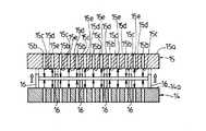
そして、図8および図9にも示すように、上記上流側および下流側搬送ステージ55,65の中央付近の周り、つまり各ガス噴出口55c,65cおよび各ガス吸引口55d,65dの周囲には、その周方向所定間隔置きに複数の昇降自在な昇降ピン71,…が設けられている。この各昇降ピン71は、図示しないアクチュエータによって昇降動し、上流側搬送ステージ55上にて浮上しているワークWの周囲を上昇時に保持するようになされている。上記各昇降ピン71の周面は、ゴム、ゲル、樹脂を主原料とする緩衝材72により被覆されている。また、上記各昇降ピン71のうちの上流側搬送ステージ55のワーク搬送方向下流側に対応する昇降ピン71および下流側搬送ステージ65のワーク搬送方向上流側に対応する昇降ピン71は、他の昇降ピン71とは別個に昇降動作するように制御されており、各昇降ピン71を全て上昇させた状態で、上流側搬送ステージ55のワーク搬送方向下流側に対応する昇降ピン71および下流側搬送ステージ65のワーク搬送方向上流側に対応する昇降ピン71のみを下降させることによって、上流側搬送ステージ55上にて浮上しているワークWを下流側搬送ステージ65上に受け渡せるように開放する両搬送ステージ55,65間の搬送経路が構成されるようになっている。そして、上記下流側搬送ステージ65のワーク搬送方向上流側に対応する昇降ピン71を除くその他の昇降ピン71は、上流側搬送ステージ55上から下流側搬送ステージ65上に受け渡される際に受け止められるように上昇している。
【0056】
次に、搬入ステージ22から搬入されたワークWを表裏反転させてから搬出ステージ32に搬送する手順について説明する。
【0057】
まず、図14および図16に示すように、搬入部2の搬入ステージ22において、各ガス噴出口から噴出したガスをワークWに衝突させたのち各ガス吸引口に吸引させることによって、搬入ステージ22上に浮上させていたワークWが上流側ワーク回転部5の上流側搬送ステージ55に搬入されると、この上流側搬送ステージ55において、供給通路55bを介して各ガス噴出口55cから噴出したガスをワークWに衝突させたのち各ガス吸引口55dから吸引通路55eを介して吸引させることによって、上流側搬送ステージ55にてワークWが浮上した状態で受け渡される。
【0058】
次いで、図17に示すように、上流側搬送ステージ55より各昇降ピン71を全て上昇させる。このとき、ワークWは、上流側搬送ステージ55上に浮上した状態で、各昇降ピン71の周面(緩衝材72)との接触により保持される。
【0059】
その後、図18にも示すように、回転軸53を支点にして上流側搬送ステージ55を図18の紙面時計回りに135°〜180°未満の傾斜角度となるまで回転させるとともに、この回転された上流側搬送ステージ55に対しワーク搬送方向に対向する傾斜角度(上流側搬送ステージ55と平行となる傾斜角度)まで下流側搬送ステージ65を回転軸64を支点にして図18に示す反時計回りに回転させる。このとき、回転軸53を支点として回転する上流側搬送ステージ55および回転軸63を支点として回転する下流側搬送ステージ65が、互いの干渉、もしくは搬入ステージ22または搬出ステージ32と干渉するおそれがある場合には、伸縮軸52,62を伸長させたり、レール49上をスライダ51,61を介して搬送方向に摺動させることで、容易に干渉回避できることになる。
【0060】
それから、図19に示すように、下流側搬送ステージ65のワーク搬送方向上流側に対応する昇降ピン71を除くその他の昇降ピン71を上昇させた後、上流側搬送ステージ55のワーク搬送方向下流側に対応する昇降ピン71のみを下降させて、両搬送ステージ55,65間に搬送経路を構成すると、ワークWは、自身の自重によって、上流側搬送ステージ55のワーク搬送方向下流側から下流側搬送ステージ65上にそのワーク搬送方向上流側を経て滑り込み、下流側搬送ステージ65での各供給通路65bを介したガス噴出口65cからのガスの噴出および各ガス吸引口65dからの吸引通路65eを介したガスの吸引により該下流側搬送ステージ65上にワークWを受け渡す。
【0061】
しかる後、上流側ワーク回転部5の回転軸53を支点にして上流側搬送ステージ55を図18の紙面反時計回りに回転させるとともに、下流側ワーク回転部6の回転軸63を支点にして下流側搬送ステージ65を時計回りに回転させて、図14および図16に示す状態に戻す。このときも、回転軸53を支点として回転する上流側搬送ステージ55および回転軸63を支点として回転する下流側搬送ステージ65が、互いの干渉、もしくは搬入ステージ22または搬出ステージ32と干渉するおそれがある場合には、伸縮軸52,62を伸長させたり、レール49上をスライダ51,61を介して搬送方向に摺動させることで、容易に干渉回避できることになる。
【0062】
その後、上流側搬送ステージ55および下流側搬送ステージ65の各昇降ピン71を全て下降させ、下流側搬送ステージ65上に浮上させていたワークWを、搬出部3の搬出ステージ32上に搬送し、この搬出ステージ32上において、各ガス噴出口から噴出したガスをワークWに衝突させたのち各ガス吸引口に吸引させることによって、搬出ステージ32にてワークWが浮上した状態で受け渡される。
【0063】
このように、ガスの噴出と吸引との同時動作により上流側搬送ステージ55上に浮上しているワークWは、各昇降ピン71を上昇させることにより周囲が保持された状態で、回転軸53を支点にして上流側搬送ステージ55を図18の紙面時計回りに135°〜180°未満の傾斜角度となるまで回転させるとともに、この回転された上流側搬送ステージ55に対しワーク搬送方向に対向する傾斜角度(上流側搬送ステージ55と平行となる傾斜角度)まで下流側搬送ステージ65を回転軸64を支点にして図18に示す反時計回りに回転させてから、下流側搬送ステージ65のワーク搬送方向上流側に対応する昇降ピン71を除くその他の昇降ピン71を上昇させた後、上流側搬送ステージ55のワーク搬送方向下流側に対応する昇降ピン71のみを下降させて両搬送ステージ55,65間に搬送経路を構成すると、自身の自重によって、上流側搬送ステージ55のワーク搬送方向下流側から下流側搬送ステージ65上にそのワーク搬送方向上流側を経て滑り込み、該下流側搬送ステージ65でのガスの噴出と吸引との同時動作により浮上した状態で受け渡される。これにより、ワークWの大型化に伴いワークWに反りが発生していたり最初から反りが発生していても、ガスの噴出と吸引との同時動作により上流側搬送ステージ55上に浮上しているワークWの周囲が各昇降ピン71の上昇により保持された状態で円滑に表裏反転されたのち、両搬送ステージ55,65間での搬送経路の構成に伴って上流側搬送ステージ55上から下流側搬送ステージ65上に浮上した状態で受け渡され、搬送、表裏反転時のワークWの落下や破損、割れ欠け等を確実に防止することができる。
【0064】
また、ワークWのチャック動作が各昇降ピン71によるシンプルな昇降動作のみにより行われ、その周囲からのパーティクル発生を最小限に抑えることができる。しかも、メカニカル部品を減らして、故障もし難くメンテナンス時の労力も軽減できる上、装置サイズも非常にコンパクトなものにすることができる。
【0065】
更に、真空チャックや静電チャックを用いたもののように、静電気の発生によってワークWやプロセスに悪影響を与えることもなく、静電気によるワークWやプロセスへの悪影響を確実に防止することができる。
【0066】
<他の実施の形態>
本発明は、上記各実施形態に限定されるものではなく、その他種々の変形例を包含している。例えば、上記各実施形態では、ワーク回転部1または上流側ワーク回転部5に対するワーク搬入部2でのワークWの搬入、もしくはワーク回転部1または下流側ワーク回転部6からのワーク搬出部2でのワークWの搬出をガスの噴出またはガスの噴出と同時吸引によりワークWを浮上させた状態で行ったが、ワークの導入、排出方法はこれに限定されるものではなく、コロ搬送や、ワークを浮上させないステージ搬送であってもよい。
【0067】
また、上記各実施形態では、ガスの噴出またはガスの噴出と同時吸引によりワークWを浮上させたが、液体の噴出または液体の噴出と同時吸引によりワークを浮上させるようにしてもよく、この場合には、ワークやプロセスに対し液体が悪影響を与えない場合に限られる。
【0068】
そして、上記各実施形態では、略矩形状のワークWを搬送する場合について述べたが、円形状のワークにも適用できるのはもちろんであり、その場合には、昇降ピンの配置を円形状のワークに則して変更すればよい。
【0069】
更に、上記第1実施形態では、第1搬送ステージ14上に複数の昇降ピン16を設けたが、第2搬送ステージ上にのみまたは両搬送ステージ上に複数の昇降ピンが設けられていてもよい。また、複数の昇降ピン16,71によりワークWの周囲を保持したが、開閉式のガイド枠などによってワークの周囲が保持されるようにしてもよい。
【0070】
【発明の効果】
以上、説明したように、各昇降ピンによりワークの周囲を保持した状態で上下一対の搬送ステージを上下反転させ、上側の搬送ステージの各昇降ピンの下降に伴って上側の搬送ステージ上から下側の搬送ステージ上にワークを流体の噴出または噴出と吸引との同時動作により浮上させた状態で受け渡すことで、搬送、表裏反転時のワークの落下や破損、割れ欠け等を確実に防止することができる。しかも、ワークのチャック動作を昇降ピンによるシンプルな昇降動作のみにより行え、その周囲からのパーティクル発生を最小限に抑えることができ、メカニカル部品を減らしてメンテナンス時の労力も軽減できる上、装置サイズも非常にコンパクトなものにすることができ、更に、静電気によるワークやプロセスへの悪影響も防止することができる。
【0071】
また、各昇降ピンによりワークの周囲を保持した状態で上下反転方向に回転させたワーク搬送方向上流側の搬送ステージでのワーク搬送方向下流側の昇降ピン、およびワーク搬送方向上流側の搬送ステージに対しワーク搬送方向に対向する傾斜角度まで回転させたワーク搬送方向下流側の搬送ステージでのワーク搬送方向上流側の昇降ピンの下降動作に伴って、ワーク搬送方向上流側の搬送ステージ上からワーク搬送方向下流側の搬送ステージ上にワークを自重により滑らせて浮上させた状態で受け渡すことで、搬送、表裏反転時のワークの落下や破損、割れ欠け等を確実に防止することができる。また、ワークのチャック動作を昇降ピンによるシンプルな昇降動作のみにより行え、その周囲からのパーティクル発生を最小限に抑えることができ、メカニカル部品を最小限に抑えてメンテナンスの簡単化および装置のコンパクト化を図ることもでき、更に、静電気の発生によるワークやプロセスへの悪影響を確実に防止することができる。
【0072】
そして、各昇降ピンを、ゴム、ゲル、樹脂を主原料とする緩衝材または防振材により被覆することで、ワークの周囲を昇降ピンによってより確実に保持して、搬送、表裏反転時のワークの落下や破損、割れ欠け等をより確実に防止することができる上、各昇降ピンの接触によるワークの損傷を防止することもできる。
【0073】
また、ワークを下側の搬送ステージに吸着した状態で上下一対の搬送ステージを上下反転させ、上側の搬送ステージ上から流体の吸引解除に伴って下側の搬送ステージ上にワークを浮上した状態で受け渡すことで、搬送、表裏反転時のワークの落下や破損、割れ欠け等を確実に防止することができる。しかも、ワークのチャック動作を流体の吸引のみにより行え、メカニカル部品によるワークのチャック動作を不要にしてパーティクル発生を可及的に抑えることができる上、メカニカル部品をなくしてメンテナンスの簡単化および装置のコンパクト化を図ることもできる。
【0074】
そして、各搬送ステージを上下方向および左右方向に移動可能に支持することで、ワークを表裏反転させる際に回転する搬送ステージと付近の部材との干渉を確実に防止し、ワークの表裏反転を円滑に行うことができる。
【図面の簡単な説明】
【図1】本発明の第1の実施形態に係わるワーク回転部にワーク搬入部からワークを搬入する状態を示すワーク搬送装置の側面図である。
【図2】同じくワーク回転部においてワークを表裏反転させる状態を示すワーク搬送装置の側面図である。
【図3】同じくワーク回転部からワーク搬出部にワークを搬出する状態を示すワーク搬送装置の側面図である。
【図4】同じくワーク搬入部から搬入したワークを浮上させている状態を示すワーク回転部の側面図である。
【図5】同じく第1および第2搬送ステージ間においてワークを浮上させた状態で昇降ピンにより周囲を保持している状態を示すワーク回転部の側面図である。
【図6】同じく昇降ピンにより周囲を保持したワークを表裏反転させる状態を示すワーク回転部の側面図である。
【図7】同じく表裏反転させたワークを第2搬送ステージ上にて浮上させている状態を示すワーク回転部の側面図である。
【図8】同じく第1搬送ステージを対向面側から見た平面図である。
【図9】同じく第1搬送ステージを対向面の斜め上方から見た斜視図である。
【図10】本発明の第2の実施形態に係わるワーク搬入部から搬入したワークを浮上させている状態を示すワーク回転部の側面図である。
【図11】同じく第1および第2ワーク搬送ステージ間において浮上させていたワークに対し第1搬送ステージでの吸引動作を開始した状態を示すワーク回転部の側面図である。
【図12】同じく第1搬送ステージ上に吸着させたワークを表裏反転させる状態を示すワーク回転部の側面図である。
【図13】同じく表裏反転させたワークの吸着を解除して第1および第2搬送ステージ間にてワークを浮上させている状態を示すワーク回転部の側面図である。
【図14】本発明の第3の実施形態に係わる上流側ワーク回転部にワーク搬入部からワークを搬入する状態を示すワーク搬送装置の側面図である。
【図15】同じく上流側ワーク回転部から下流側ワーク回転部にワークを受け渡す状態を示すワーク搬送装置の側面図である。
【図16】同じくワーク搬入部から搬入したワークを浮上させている状態を示す上流側ワーク回転部の側面図である。
【図17】同じくワークを浮上させた状態で昇降ピンにより周囲を保持している状態を示す上流側ワーク回転部の側面図である。
【図18】同じく昇降ピンにより周囲を保持したワークを表裏反転させる状態を示す上流側ワーク回転部の側面図である。
【図19】同じく上流側搬送ステージから下流側搬送ステージにワークを受け渡す状態を示す上流側ワーク回転部から下流側ワーク回転部の側面図である。
【図20】従来例に係わるワーク搬送装置の斜視図である。
【図21】同じくメカチャック手段の詳細を示す斜視図である。
【符号の説明】
14 第1搬送ステージ(搬送ステージ)
15 第2搬送ステージ(搬送ステージ)
16 昇降ピン
17 緩衝材
41 第1搬送ステージ(搬送ステージ)
42 第2搬送ステージ(搬送ステージ)
55 上流側搬送ステージ(搬送ステージ)
65 下流側搬送ステージ(搬送ステージ)
71 昇降ピン
72 緩衝材
W ワーク
X ワーク搬送装置[0001]
BACKGROUND OF THE INVENTION
The present invention relates to a work transfer device for transferring a work such as a glass substrate or a semiconductor wafer when manufacturing a semiconductor, a liquid crystal display element, a flat panel display such as EL and PDP, a solar battery panel, and the like. This is related to measures for smoothly turning the work upside down in order to perform backside processing or double-sided processing.
[0002]
[Prior art]
2. Description of the Related Art Conventionally, in manufacturing sites for semiconductors, flat panel displays, solar cells, etc., it has become necessary to reverse the front and back of workpieces in processes such as glass substrate and semiconductor wafer (hereinafter collectively referred to as workpiece) cleaning and photo processing. In some cases, the workpiece is inverted while supporting the end portion of the workpiece using a chuck mechanism such as a mechanical chuck, a vacuum chuck, or an electrostatic chuck or sucking the back surface of the workpiece.
[0003]
As such a workpiece transfer device, as shown in FIGS. 20 and 21, the workpiece a is transferred to four transfer positions P1 to P4 (the transfer position P1 is a position after applying the coating liquid, P2 is the workpiece side surface cleaning processing position, P3. Is transferred to a standby position, and P4 is transferred to a post-process position), and the workpiece a is transferred by being reversed between the transfer positions P1 to P2 (for example, see Patent Document 1). The work a is turned upside down in the state where the periphery of the work a is chucked at a predetermined position by the chuck pieces c of the plurality of mechanical chuck means b,... The rotation is driven in the direction of the arrow e using a motor that does not perform as a drive source. The chucking operation of the workpiece a by the chuck piece of each chuck means b is performed via a slide shaft g that slides by direct driving by the air cylinder f. In this case, the transfer between the transfer positions P1 to P4 of the workpiece is performed by another robot (not shown).
[0004]
[Patent Document 1]
JP-A-10-264071
[0005]
[Problems to be solved by the invention]
However, in the above-described conventional workpiece transfer device, since the workpiece a is chucked by the chuck pieces c of the plurality of mechanical chuck means b,... Is low. For this reason, problems such as work dropping, breakage, cracking, and the like during conveyance and reversing of the front and back are likely to occur. Moreover, if the workpiece is warped from the beginning, chucking becomes increasingly difficult.
[0006]
In addition, since the chucking operation is performed via the slide shaft g, there is a concern about generation of particles from the slide shaft, the sliding portion, and the rotation driving portion. In addition, since there are many mechanical parts and the apparatus configuration is complicated, the apparatus is likely to break down, requires a large amount of labor during maintenance, and increases the apparatus size.
[0007]
Furthermore, even when a vacuum chuck or an electrostatic chuck is used instead of the mechanical chuck, there is a possibility that the work or process may be affected by the generation of static electricity.
[0008]
The present invention has been made in view of such points, and the object of the present invention is that the work can be reliably reversed without causing a work drop, breakage, crack chipping, etc. at the time of conveyance and reversing the front and back, It is an object of the present invention to provide a workpiece transfer device capable of minimizing mechanical parts, simplifying maintenance and downsizing the device, and reliably preventing adverse effects on workpieces and processes due to static electricity.
[0009]
[Means for Solving the Problems]
In order to achieve the above object, in the present invention, a pair of transfer stages that lift and transfer a work by squirting a fluid or simultaneously ejecting and sucking a fluid are arranged so as to face each other in the vertical direction. A plurality of elevating pins that hold the periphery of the workpiece can be provided on at least one of the transfer stages, and a rotation mechanism that rotates the pair of transfer stages so that the pair of transfer stages can be turned upside down is provided. Then, the workpiece is transferred from the upper transfer stage to the lower transfer stage as each of the elevating pins descends on the upper transfer stage turned upside down by the rotating mechanism.
[0010]
Due to this specific matter, the work floating on one transfer stage due to the ejection of fluid or the simultaneous operation of ejection and suction is rotated by a rotating mechanism while the periphery is held by raising the lifting pins. When the lift pins are lowered after the pair of transfer stages are turned upside down, the lower transfer stage moves from the upper transfer stage to the lower transfer stage. It is delivered in a floating state by the simultaneous operation of the ejection of the fluid or the ejection and suction. As a result, even if the workpiece is warped or warped from the beginning due to the increase in size of the workpiece, the workpiece is floating on one transfer stage due to the ejection of fluid or the simultaneous operation of ejection and suction After the front and back are smoothly reversed while being held by the lift of the lift pins, the surface of the lift is lifted from the upper transport stage to the lower transport stage as each lift pin is lowered on the upper transport stage. It is possible to reliably prevent the workpiece from dropping, breaking, cracking, etc. during conveyance and reversing the front and back.
[0011]
Further, the chucking operation of the workpiece is performed only by a simple raising / lowering operation by the raising / lowering pins, and the generation of particles from the surroundings can be minimized. In addition, the number of mechanical parts is reduced, so that failure is difficult and labor for maintenance is reduced, and the apparatus size is very compact.
[0012]
Further, unlike the case where a vacuum chuck or an electrostatic chuck is used, the work or process is not adversely affected by the generation of static electricity.
[0013]
In addition, as another method, the transfer stage that floats and conveys the workpiece by the simultaneous operation of the ejection of the fluid or the ejection and suction is arranged so as to face each other in the conveyance direction of the workpiece. A plurality of elevating pins that can be moved up and down to hold the periphery of the work are provided, and among these elevating pins, the elevating pins corresponding to the downstream side of the work transfer direction of the transfer stage on the upstream side of the work transfer direction and the downstream side of the work transfer direction The lifting pins corresponding to the upstream side of the transfer stage in the workpiece transfer direction are controlled to move up and down separately from the other lifting pins, and the transfer stage upstream of the transfer direction of the workpiece is less than 180 degrees in the upside down direction. A first rotation mechanism that rotates to an inclination angle, and a work stage that is rotated by the first rotation mechanism and that is upstream of the work transfer direction. To the inclined position facing the click conveying direction and a second rotating mechanism for rotating the transfer stage of the work conveying direction downstream side. Then, a lifting pin on the downstream side of the workpiece conveyance direction on the conveyance stage on the upstream side of the workpiece conveyance direction rotated in the upside down direction by the first rotation mechanism and the conveyance on the downstream side of the workpiece conveyance direction rotated by the second rotation mechanism. As the lifting pin on the upstream side of the workpiece transfer direction on the stage descends, the workpiece is slid by its own weight from the transfer stage on the upstream side of the workpiece transfer direction to the transfer stage on the downstream side of the workpiece transfer direction. Yes.
[0014]
Due to this specific matter, the work floating on the transport stage upstream in the work transport direction due to the ejection of fluid or the simultaneous operation of the jet and suction is held in a state where the periphery is held by raising the lifting pins. The first rotation mechanism is rotated up to an angle of less than 180 degrees in the upside down direction to incline the conveyance stage on the upstream side of the workpiece conveyance direction, and then the lifting pin on the downstream side of the workpiece conveyance direction on the conveyance stage on the upstream side of the workpiece conveyance direction and When the lifting pin on the upstream side of the workpiece conveyance direction is lowered on the conveyance stage downstream of the workpiece conveyance direction, the lowering pin on the upstream side of the workpiece conveyance direction moves from the conveyance stage upstream of the workpiece conveyance direction to the conveyance stage downstream of the workpiece conveyance direction. Glide by its own weight while floating by the simultaneous operation of jetting or sucking of fluid on the transfer stage downstream in the workpiece transfer direction Received is passed. As a result, even if the workpiece is warped or warped from the beginning as the workpiece becomes larger, it floats on the transfer stage on the upstream side of the workpiece transfer direction by the ejection of fluid or the simultaneous operation of ejection and suction After the workpiece is turned upside down smoothly while being held up by the lifting pins, the lifting pins on the downstream side of the workpiece conveyance direction and the downstream side of the workpiece conveyance direction on the conveyance stage upstream of the workpiece conveyance direction. As the lifting pin on the upstream side of the workpiece transfer direction on the transfer stage descends, the workpiece is slid in a state where it floats on the transfer stage on the downstream side of the workpiece transfer direction from the transfer stage on the upstream side of the workpiece transfer direction. It is possible to reliably prevent the workpiece from dropping, breaking, cracking, etc. during conveyance and reversing the front and back.
[0015]
In addition, the workpiece chucking operation is performed only by a simple lifting operation using the lifting pins, and it is possible to minimize the generation of particles from the surroundings, minimizing mechanical parts and reducing the number of failures, simplifying maintenance. It is also possible to make the device compact.
[0016]
Furthermore, it is possible to reliably prevent adverse effects on the work and process due to the generation of static electricity.
[0017]
Here, when each lifting pin is covered with a cushioning material or vibration proofing material mainly made of rubber, gel, or resin, when the workpiece is turned upside down, the periphery of the workpiece is more reliably secured by the lifting pins. It will be held, and it will be possible to more reliably prevent the workpiece from dropping, breaking, cracking, etc. during conveyance and reversing the front and back. In addition, it is possible to prevent damage to the workpiece due to contact when the periphery of the workpiece is held by the lift pins.
[0018]
Furthermore, as another method, a pair of transfer stages that lift and transfer a workpiece by fluid ejection or simultaneous operation of jetting and suction are arranged facing each other in the vertical direction. A rotation mechanism is provided that rotates the pair of transfer stages so that they can be turned upside down in a state where a workpiece is adsorbed to at least one transfer stage by suction of fluid. Then, the workpiece is transferred from the upper transfer stage turned upside down by the rotating mechanism to the lower transfer stage as the fluid is released.
[0019]
Due to this specific matter, a workpiece that is floating on one transfer stage by the simultaneous operation of fluid ejection or ejection and suction is rotated in a state where the workpiece is attracted to this one transfer stage by suction of fluid. After the pair of transfer stages are turned upside down by rotating by the mechanism, when the suction of the fluid is released from the upper one transfer stage, the upper one transfer stage is lowered from the upper side as the suction is released. On the other transport stage on the side, the fluid is ejected on the other transport stage or delivered in a state of floating by the simultaneous operation of the ejection and suction. As a result, even if the workpiece is warped or warped from the beginning due to the increase in size of the workpiece, the workpiece is floating on one transfer stage due to the ejection of fluid or the simultaneous operation of ejection and suction When the fluid is sucked onto one of the transfer stages and smoothly turned upside down while being sucked by suction of the fluid, the suction of the fluid at one of the transfer stages is released and the lower side of the transfer stage is changed from the upper side to the lower side. It is delivered in a state where it floats on the other transfer stage, and it is possible to reliably prevent the workpiece from dropping, breaking, cracking, etc. during transfer and reversing the front and back.
[0020]
Also, the workpiece chucking operation is performed only by suction of the fluid, and the workpiece chucking operation by mechanical parts is unnecessary, which makes it possible to suppress the generation of particles as much as possible. It is also possible to reduce the size of the apparatus.
[0021]
When each transfer stage is supported so as to be movable in the vertical and horizontal directions, the transfer stage that rotates when the work is turned upside down is reliably prevented from interfering with nearby members. Therefore, it is possible to smoothly turn the work upside down.
[0022]
DETAILED DESCRIPTION OF THE INVENTION
(Embodiment 1)
Hereinafter, embodiments of the present invention will be described with reference to the drawings.
[0023]
<First Embodiment>
1 to 3 show a workpiece transfer device X according to the first embodiment of the present invention, in which 1 is a workpiece rotating unit for turning the workpiece W upside down, and 2 is a workpiece loading unit for loading the workpiece W into the workpiece rotating unit 1.
[0024]
The work rotating unit 1 includes a pair of left and right support legs 11 (shown only on the front side in FIG. 1 to FIG. 3) installed on the base table Xa, and a telescopic shaft that moves up and down with respect to the
[0025]
As shown in FIGS. 8 and 9, there is a predetermined circumferential direction around the center of the facing surface 14a of the
[0026]
Also, as shown in FIGS. 1 to 3, the work carry-in
[0027]
Next, a procedure for reversing the work W carried in from the carry-in
[0028]
First, as shown in FIG. 1 and FIG. 4, in the carry-in
[0029]
Next, as shown in FIG. 5, in the upper second transfer stage 15 (opposing
[0030]
Thereafter, as shown in FIG. 2, the first and second transport stages 14 and 15 are rotated 180 degrees clockwise in FIG. 6 with the
[0031]
Then, as shown in FIG. 7, each lifting
[0032]
Thereafter, the workpiece W that has been floated on the
[0033]
At this time, the
[0034]
As described above, the work W floating on the
[0035]
Further, the chucking operation of the workpiece W is performed only by a simple raising / lowering operation by the raising / lowering pins 16, and the generation of particles from the surroundings can be minimized. In addition, the number of mechanical parts can be reduced, so that failure can be prevented and labor for maintenance can be reduced, and the apparatus size can be made very compact.
[0036]
Further, unlike the case using a vacuum chuck or an electrostatic chuck, the work W or process is not adversely affected by the generation of static electricity, and the adverse effect on the work W or process due to static electricity can be reliably prevented.
[0037]
<Second Embodiment>
Next, a second embodiment of the present invention will be described with reference to FIGS.
[0038]
In this embodiment, the configuration of the first and second transfer stages is changed. The other configurations except for the first and second transfer stages are the same as those in the first embodiment, and the same portions are denoted by the same reference numerals, and detailed description thereof is omitted.
[0039]
That is, in the present embodiment, as shown in FIGS. 10 to 13, a plurality of
[0040]
Next, a procedure for reversing the work W carried in from the carry-in
[0041]
First, as shown in FIG. 10, when the work W that has been floated on the carry-in
[0042]
Next, as shown in FIG. 11, the ejection of the gas from the
[0043]
Thereafter, as shown in FIG. 12, the workpiece W is adsorbed on the opposing
[0044]
Then, as shown in FIG. 13, the suction of the gas through the
[0045]
Thereafter, the workpiece W that has been floated on the
[0046]
At this time, the
[0047]
As described above, the workpiece W floating on the lower
[0048]
In addition, the chucking operation of the workpiece W is performed only by the suction of fluid, and the chucking operation of the workpiece by the mechanical parts is unnecessary, so that the generation of particles can be suppressed as much as possible. The device can also be made compact.
[0049]
<Third Embodiment>
Next, a third embodiment of the present invention will be described with reference to FIGS.
[0050]
In this embodiment, the configuration of the workpiece rotating unit is changed. The other configurations except for the work rotating portion are the same as those in the first embodiment, and the same portions are denoted by the same reference numerals and detailed description thereof is omitted.
[0051]
That is, in this embodiment, as shown in FIGS. 14 and 15, between the workpiece carry-in
[0052]
The upstream
[0053]
On the other hand, the downstream-side workpiece rotating unit 6 is slidably supported on the downstream side (left side in FIGS. 14 and 15) of the pair of left and
[0054]
The upstream and downstream transfer stages 55 and 65 have a substantially rectangular shape in plan view, and a gas supplied from a gas supply tank or a cylinder (not shown) is supplied near the center of the
[0055]
As shown in FIGS. 8 and 9, around the centers of the upstream and downstream transfer stages 55 and 65, that is, around the
[0056]
Next, a procedure for reversing the work W carried in from the carry-in
[0057]
First, as shown in FIGS. 14 and 16, in the carry-in
[0058]
Next, as shown in FIG. 17, all the lifting pins 71 are lifted from the
[0059]
Thereafter, as shown in FIG. 18, the
[0060]
Then, as shown in FIG. 19, after raising the other lifting pins 71 except the lifting pins 71 corresponding to the upstream side of the
[0061]
Thereafter, the
[0062]
Thereafter, all the lifting pins 71 of the
[0063]
As described above, the work W floating on the upstream-
[0064]
Further, the chucking operation of the workpiece W is performed only by a simple raising / lowering operation by the raising / lowering pins 71, and the generation of particles from the surroundings can be minimized. In addition, the number of mechanical parts can be reduced, so that failure can be prevented and labor for maintenance can be reduced, and the apparatus size can be made very compact.
[0065]
Further, unlike the case using a vacuum chuck or an electrostatic chuck, the work W or process is not adversely affected by the generation of static electricity, and the adverse effect on the work W or process due to static electricity can be reliably prevented.
[0066]
<Other embodiments>
The present invention is not limited to the above-described embodiments, and includes various other modifications. For example, in each of the above-described embodiments, the work W is carried into the work rotation unit 1 or the upstream
[0067]
In each of the above embodiments, the workpiece W is levitated by gas suction or simultaneous suction and ejection of gas. However, the workpiece may be levitated by liquid ejection or simultaneous suction and liquid ejection. Is limited to the case where the liquid does not adversely affect the workpiece or process.
[0068]
In each of the above embodiments, the case where the substantially rectangular workpiece W is transported has been described. However, the present invention can also be applied to a circular workpiece, and in that case, the lifting pins are arranged in a circular shape. Change according to the workpiece.
[0069]
Furthermore, in the first embodiment, the plurality of lifting
[0070]
【The invention's effect】
As described above, the pair of upper and lower transfer stages are turned upside down while the periphery of the work is held by each lift pin, and the upper transfer stage is lowered from the upper transfer stage as each lift pin of the upper transfer stage is lowered. By transferring the workpiece on the transfer stage in a state of floating by the simultaneous operation of fluid ejection or ejection and suction, it is possible to reliably prevent the workpiece from dropping, breaking, cracking, etc. during conveyance and reversing the front and back. Can do. In addition, the workpiece chucking operation can be performed only by a simple lifting operation using the lifting pins, the generation of particles from the surroundings can be minimized, the number of mechanical parts can be reduced, the labor for maintenance can be reduced, and the equipment size can also be reduced. It can be made very compact, and further, adverse effects on the work and process due to static electricity can be prevented.
[0071]
In addition, the lift pins on the downstream side of the workpiece transfer direction on the transfer stage upstream of the workpiece transfer direction and the transfer stage on the upstream side of the workpiece transfer direction are rotated in the upside down direction while the periphery of the workpiece is held by the lift pins. On the other hand, the workpiece is conveyed from the upstream conveyance stage on the upstream side of the workpiece conveyance direction in accordance with the descending operation of the lifting pins on the upstream side of the workpiece conveyance direction on the conveyance stage on the downstream side of the workpiece conveyance direction rotated to an inclination angle facing the workpiece conveyance direction. By passing the workpiece on the conveyance stage on the downstream side in the direction while being slid and lifted by its own weight, it is possible to reliably prevent the workpiece from dropping, breaking, cracking, etc. during conveyance and reversing the front and back. In addition, the workpiece can be chucked only by a simple lifting operation using the lifting pins, minimizing the generation of particles from its surroundings, minimizing mechanical parts, simplifying maintenance, and reducing the size of the equipment. In addition, adverse effects on workpieces and processes due to the generation of static electricity can be reliably prevented.
[0072]
Then, by covering each lifting pin with a cushioning material or vibration proofing material mainly composed of rubber, gel, or resin, the workpiece is more securely held around the workpiece by the lifting pins, so that the workpiece can be transported and turned upside down. Can be more reliably prevented, and damage to the workpiece due to the contact of each lifting pin can be prevented.
[0073]
In addition, with the workpiece attracted to the lower transfer stage, the pair of upper and lower transfer stages are turned upside down, and the workpiece is floated on the lower transfer stage as the fluid is released from the upper transfer stage. By delivering the workpiece, it is possible to reliably prevent the workpiece from dropping, breaking, cracking, etc. during conveyance and reversing the front and back. In addition, the workpiece chucking operation can be performed only by suction of the fluid, and the chucking operation of the workpiece by the mechanical parts is unnecessary, so that the generation of particles can be suppressed as much as possible. It can also be made compact.
[0074]
And by supporting each transfer stage so that it can move in the vertical and horizontal directions, it is possible to reliably prevent interference between the rotating transfer stage and nearby members when the work is turned upside down, and the work can be turned upside down smoothly. Can be done.
[Brief description of the drawings]
FIG. 1 is a side view of a workpiece transfer device showing a state in which a workpiece is carried from a workpiece carry-in unit to a workpiece rotating unit according to the first embodiment of the present invention.
FIG. 2 is a side view of the workpiece transfer device showing a state in which the workpiece is turned upside down in the workpiece rotating unit.
FIG. 3 is a side view of the workpiece transfer device showing a state in which the workpiece is unloaded from the workpiece rotating unit to the workpiece unloading unit.
FIG. 4 is a side view of the workpiece rotating unit showing a state where the workpiece carried in from the workpiece carrying-in unit is also levitated.
FIG. 5 is a side view of the workpiece rotating unit showing a state in which the periphery is held by lift pins while the workpiece is lifted between the first and second transfer stages.
FIG. 6 is a side view of the workpiece rotating unit showing a state in which the workpiece whose periphery is held by the lift pins is reversed.
FIG. 7 is a side view of the workpiece rotating unit showing a state where the workpiece that has been similarly turned upside down is levitated on the second transfer stage.
FIG. 8 is a plan view of the first transfer stage as viewed from the opposite surface side.
FIG. 9 is a perspective view of the first transfer stage as viewed obliquely from above the opposing surface.
FIG. 10 is a side view of a workpiece rotating unit showing a state in which a workpiece loaded from a workpiece loading unit according to the second embodiment of the present invention is levitated.
FIG. 11 is a side view of the workpiece rotating unit showing a state in which a suction operation on the first transfer stage is started for a workpiece that has also floated between the first and second workpiece transfer stages.
FIG. 12 is a side view of the workpiece rotating unit showing a state in which the workpiece sucked on the first transfer stage is turned upside down.
FIG. 13 is a side view of the workpiece rotating unit showing a state where the suction of the workpiece that has been turned upside down is released and the workpiece is floated between the first and second transfer stages.
FIG. 14 is a side view of a workpiece transfer device showing a state in which a workpiece is carried from a workpiece carry-in portion to an upstream-side workpiece rotation unit according to the third embodiment of the present invention.
FIG. 15 is a side view of the workpiece transfer device showing a state in which the workpiece is transferred from the upstream workpiece rotating portion to the downstream workpiece rotating portion.
FIG. 16 is a side view of the upstream-side work rotation unit showing a state where the work carried in from the work carry-in unit is also levitated.
FIG. 17 is a side view of the upstream-side workpiece rotating unit showing a state where the periphery is similarly held by the lifting pins while the workpiece is levitated.
FIG. 18 is a side view of the upstream-side workpiece rotating unit showing a state in which the workpiece whose periphery is held by the lift pins is reversed upside down.
FIG. 19 is a side view of the downstream workpiece rotating unit from the upstream workpiece rotating unit showing a state in which the workpiece is transferred from the upstream conveying stage to the downstream conveying stage.
FIG. 20 is a perspective view of a workpiece transfer apparatus according to a conventional example.
FIG. 21 is a perspective view showing details of the mechanical chuck means.
[Explanation of symbols]
14 First transfer stage (transfer stage)
15 Second transfer stage (transfer stage)
16 Lift pin
17 cushioning material
41 First transfer stage (transfer stage)
42 Second transfer stage (transfer stage)
55 Upstream transfer stage (transfer stage)
65 Downstream transfer stage (transfer stage)
71 Lift pin
72 cushioning material
W Work
X Work transfer device
Claims (5)
Translated fromJapanese上記一対の搬送ステージのうちの少なくとも一方の搬送ステージ上には、ワークの周囲を保持する昇降自在な複数の昇降ピンが設けられており、
上記一対の搬送ステージを上下反転可能に回転させる回転機構を備えていて、
流体の噴出もしくは噴出と吸引との同時動作により上下の搬送ステージ間の中立位置にワークを浮上させるとともに、上昇した昇降ピンによりワークの周囲を保持した状態で、上記回転機構により一対の搬送ステージを上下反転させ、上記昇降ピンの下降に伴って、反転された上側の搬送ステージ上から下側の搬送ステージ上にワークを浮上させた状態で受け渡すようになされていることを特徴とするワーク搬送装置。A pair of transfer stages that lift and transfer a workpiece by the simultaneous operation of jetting of fluid or jetting and suction are arranged facing each other in the vertical direction,
On at least one of the pair of transfer stages, there are provided a plurality of elevating pins that can move up and down to hold the periphery of the workpiece,
A rotation mechanism for rotating the pair of transfer stages so as to be turned upside down,
The work is levitated to the neutral position between the upper and lower transfer stages by jetting the fluid or by the simultaneous operation of the jet and suction, and thepair of transfer stages ismoved by the rotating mechanismwhile the periphery of the work is held by the raised lift pins. Inverted upand down, and the workpiece is transferredin a state where the workpiece isfloated on the lower transfer stage fromthe inverted upper transfer stage as theelevating pin is lowered. Work transfer device.
上記各搬送ステージ上には、ワークの周囲を保持する昇降自在な複数の昇降ピンが設けられているとともに、この各昇降ピンのうちのワーク搬送方向上流側の搬送ステージのワーク搬送方向下流側に対応する昇降ピンおよびワーク搬送方向下流側の搬送ステージのワーク搬送方向上流側に対応する昇降ピンは、他の昇降ピンとは別個に昇降動作するように制御されており、
上記ワーク搬送方向上流側の搬送ステージを上下反転方向に180度未満の傾斜角度まで回転させる第1回転機構と、この第1回転機構により回転されたワーク搬送方向上流側の搬送ステージに対しワーク搬送方向に対向する傾斜角度までワーク搬送方向下流側の搬送ステージを回転させる第2回転機構とを備えていて、
流体の噴出と吸引との同時動作によりワーク搬送方向上流側の搬送ステージ上にワークを浮上させるとともに、上昇した昇降ピンによりワークの周囲を保持した状態で、上記第1回転機構により上流側の搬送ステージを上下反転方向に回転させ、
回転させた上流側の搬送ステージでのワーク搬送方向下流側の昇降ピンおよび上記第2回転機構により回転されたワーク搬送方向下流側の搬送ステージでのワーク搬送方向上流側の昇降ピンの下降により、両搬送ステージ間にワークの搬送経路を構成して、
ワーク搬送方向上流側の搬送ステージ上からワーク搬送方向下流側の搬送ステージ上へ、流体の噴出と吸引との同時動作によりワークを浮上させた状態で、自重により滑らせて受け渡すようになされていることを特徴とするワーク搬送装置。The transport stage for floating and transporting the workpiece by the simultaneous operation of the ejection of the fluid or the ejection and suction is arranged so as to face each other in the workpiece transport direction,
A plurality of elevating pins that can move up and down to hold the periphery of the workpiece are provided on each of the above-described conveyance stages, and the conveyance stage on the upstream side of the workpiece conveyance direction of each of the elevation pins on the downstream side of the workpiece conveyance direction. The corresponding lifting pins and the lifting pins corresponding to the upstream side of the workpiece transfer direction of the transfer stage on the downstream side of the workpiece transfer direction are controlled to move up and down separately from the other lifting pins,
A first rotation mechanism that rotates the conveyance stage upstream of the workpiece conveyance direction in the upside down direction to an inclination angle of less than 180 degrees, and workpiece conveyance with respect to the conveyance stage upstream of the workpiece conveyance direction rotated by the first rotation mechanism A second rotation mechanism that rotates the conveyance stage on the downstream side in the workpiece conveyance direction to an inclination angle facing the direction,
The simultaneous operation of the suction and ejection of the fluid with floating the workpiece on the conveying stage of the work conveying direction upstream side, the elevated lift pins while maintaining the periphery of the workpiece,transport of the upstream side by the first rotation mechanism Rotate thestage upside down,
By lowering the lift pins on the downstream side of the workpiece transfer direction on the upstream transfer stage rotated and the lift pins on the upstream side of the workpiece transfer direction on the transfer stage downstream of the workpiece transfer direction rotated by the second rotation mechanism, Configure a workpiece transfer path between both transfer stages,
The workpieceis lifted by the simultaneous operation of fluid ejection and suction from the transfer stage on the upstream side of the workpiece transfer direction to the transfer stage on the downstream side of the workpiece transfer direction. A workpiece transfer device characterized by comprising:
各昇降ピンは、ゴム、ゲル、樹脂を主原料とする緩衝材または防振材により被覆されて、ワークの周囲と昇降ピンの周面との接触によりワークを保持しうることを特徴とするワーク搬送装置。In the workpiece conveyance apparatus of Claim 1 or Claim 2,
Each lift pin, rubber, gel, resin is coated with a buffer material or vibration isolating material as a main rawmaterial, and wherein the Rukotobovine holding the workpiece by contact with the peripheral surface around the lifting pin of the workpiece Work transfer device.
この一対の搬送ステージのうちの少なくとも一方の搬送ステージに対しワークを流体の吸引により吸着させた状態で、上記一対の搬送ステージを上下反転可能に回転させる回転機構を備えていて、
流体の吸引によってワークを搬送ステージ上に吸着させた状態で上記回転機構により一対の搬送ステージを上下反転させ、反転された上側の搬送ステージでの流体の吸引を停止させるとともに、下側の搬送ステージでの流体の噴出と吸引との同時動作により、上側の搬送ステージ上から下側の搬送ステージ上にワークを浮上させた状態で受け渡すようになされていることを特徴とするワーク搬送装置。A pair of transfer stages that lift and transfer a workpiece by the simultaneous operation of jetting of fluid or jetting and suction are arranged facing each other in the vertical direction,
A rotating mechanism that rotates the pair of transfer stages so that they can be turned upside down in a state in which the workpiece is adsorbed by suction of a fluid to at least one of the pair of transfer stages;
While the work is attracted onto the transfer stage by the suction of the fluid, thepair of transfer stages areturned upside down by the rotating mechanism, the suction of the fluid at theinverted upper transfer stageis stopped, and the lower side of the transfer stageis stopped. A workpiece transfer device, wherein the workpiece is transferred ina state of beingfloated from the upper transfer stage to the lower transfer stageby simultaneous operation of fluid ejection and suction on the transfer stage. .
各搬送ステージは、上下方向および左右方向に移動可能に支持されていることを特徴とするワーク搬送装置。In the workpiece conveyance apparatus as described in any one of Claim 1 thru | or 4,
Each conveyance stage is supported so that movement to an up-down direction and a left-right direction is possible, The workpiece conveyance apparatus characterized by the above-mentioned.
Priority Applications (2)
| Application Number | Priority Date | Filing Date | Title |
|---|---|---|---|
| JP2003075948AJP4197129B2 (en) | 2003-03-19 | 2003-03-19 | Work transfer device |
| US10/799,142US7128516B2 (en) | 2003-03-19 | 2004-03-11 | Workpiece transport apparatus |
Applications Claiming Priority (1)
| Application Number | Priority Date | Filing Date | Title |
|---|---|---|---|
| JP2003075948AJP4197129B2 (en) | 2003-03-19 | 2003-03-19 | Work transfer device |
Publications (2)
| Publication Number | Publication Date |
|---|---|
| JP2004284698A JP2004284698A (en) | 2004-10-14 |
| JP4197129B2true JP4197129B2 (en) | 2008-12-17 |
Family
ID=33094830
Family Applications (1)
| Application Number | Title | Priority Date | Filing Date |
|---|---|---|---|
| JP2003075948AExpired - Fee RelatedJP4197129B2 (en) | 2003-03-19 | 2003-03-19 | Work transfer device |
Country Status (2)
| Country | Link |
|---|---|
| US (1) | US7128516B2 (en) |
| JP (1) | JP4197129B2 (en) |
Cited By (1)
| Publication number | Priority date | Publication date | Assignee | Title |
|---|---|---|---|---|
| KR101146609B1 (en)* | 2010-04-08 | 2012-05-16 | 주식회사 태성기연 | Apparatus for transferring of glass panel |
Families Citing this family (53)
| Publication number | Priority date | Publication date | Assignee | Title |
|---|---|---|---|---|
| AU2003285937A1 (en)* | 2002-10-22 | 2004-05-13 | University Of Vermont And State Agriculture College | Symbiotic food products comprising oats and methods for manufacturing the same |
| EP1690660A1 (en)* | 2003-12-04 | 2006-08-16 | Mitsuboshi Diamond Industrial Co., Ltd. | Substrate machining method, substrate machining device, substrate carrying method, and substrate carrying mechanism |
| CN101124133A (en)* | 2004-04-14 | 2008-02-13 | 科福罗科学解决方案有限公司 | Non-contact support platform for distance adjustment |
| DE602005018772D1 (en)* | 2004-05-02 | 2010-02-25 | K J Maskinfabriken As | SYSTEM FOR REVERSING MEAT PIECES WITH AN UNREGULAR GEOMETRIC FORM |
| KR100628276B1 (en)* | 2004-11-05 | 2006-09-27 | 엘지.필립스 엘시디 주식회사 | Scribing equipment and substrate cutting device having same and substrate cutting method using same |
| AT501192B1 (en)* | 2004-12-23 | 2007-04-15 | Lisec Peter | DEVICE FOR TRANSPORTING AND SUPPORTING TABLE OBJECTS, ESPECIALLY GLASS PANELS |
| JP5160216B2 (en)* | 2007-12-28 | 2013-03-13 | 株式会社東京自働機械製作所 | Box reversing device |
| US20090199383A1 (en)* | 2008-02-13 | 2009-08-13 | Winter Jr Richard L | Method and apparatus for inverting a vehicle assembly |
| JP5334443B2 (en)* | 2008-04-02 | 2013-11-06 | 日本メクトロン株式会社 | Plate work reversing device |
| US20100203242A1 (en)* | 2009-02-06 | 2010-08-12 | Applied Materials, Inc. | self-cleaning susceptor for solar cell processing |
| EP2396701B1 (en)* | 2009-02-13 | 2015-04-08 | Micronic Mydata AB | Multi-table lithographic systems |
| US20110135405A1 (en)* | 2009-12-04 | 2011-06-09 | Akira Miyaji | Roller apparatus and transportation apparatus |
| JP5835722B2 (en)* | 2009-12-10 | 2015-12-24 | オルボテック エルティ ソラー,エルエルシー | Automatic ranking multi-directional serial processor |
| US8459276B2 (en) | 2011-05-24 | 2013-06-11 | Orbotech LT Solar, LLC. | Broken wafer recovery system |
| EP2592662A1 (en)* | 2011-11-11 | 2013-05-15 | Somont GmbH | System and method for assembling a solar cell matrix |
| CN103848193A (en)* | 2012-12-04 | 2014-06-11 | 浚丰太阳能(江苏)有限公司 | Online turning mechanism for photovoltaic module |
| JP6126396B2 (en)* | 2013-02-07 | 2017-05-10 | 三星ダイヤモンド工業株式会社 | Substrate processing equipment |
| KR102154706B1 (en)* | 2013-03-20 | 2020-09-11 | 삼성디스플레이 주식회사 | Deposition apparatus, method for manufacturing organic light emitting display apparatus using the same, and organic light emitting display apparatus manufactured by the same |
| KR101451506B1 (en)* | 2013-04-17 | 2014-10-17 | 삼성전기주식회사 | Pcb transfer device in noncontact way |
| CN103662165A (en)* | 2013-07-19 | 2014-03-26 | 颐中(青岛)烟草机械有限公司 | Cigarette pile transversal and vertical converting device |
| CN103754608B (en)* | 2014-01-07 | 2015-12-02 | 福耀玻璃工业集团股份有限公司 | A kind of glass turnover device |
| CN104035220A (en)* | 2014-05-30 | 2014-09-10 | 京东方科技集团股份有限公司 | Rotation device |
| CN105712089B (en)* | 2016-04-21 | 2017-10-17 | 江苏科技大学 | A kind of control method of non-contacted conveyance and locating platform device |
| CN106078405A (en)* | 2016-07-25 | 2016-11-09 | 长兴科艺玻璃工艺品有限公司 | A kind of fixing and turning device for face glass processing |
| CN106078404A (en)* | 2016-07-25 | 2016-11-09 | 长兴科艺玻璃工艺品有限公司 | A kind of face glass processing edging device |
| CN108249159B (en)* | 2016-12-28 | 2020-02-14 | 芝浦机械电子株式会社 | Floating transfer device and substrate processing device |
| CN106628982A (en)* | 2017-03-06 | 2017-05-10 | 常州亿晶光电科技有限公司 | Solar cell panel turnover device |
| CN108666232B (en)* | 2017-03-28 | 2021-11-12 | 雷仲礼 | Substrate processing system, substrate turnover device and method |
| CN107585539A (en)* | 2017-09-20 | 2018-01-16 | 武汉华星光电技术有限公司 | Sheet material movement system |
| CN111295336B (en)* | 2017-09-28 | 2021-11-16 | 法比奥·泼尼股份公司 | Packaging machine with turning and stacking device |
| CN107857092B (en)* | 2017-10-19 | 2023-10-20 | 江苏杰士德精密工业有限公司 | Automatic soft board overturning equipment and operation method thereof |
| JP7109904B2 (en) | 2017-11-02 | 2022-08-01 | 株式会社東芝 | take-out system |
| US10804133B2 (en)* | 2017-11-21 | 2020-10-13 | Taiwan Semiconductor Manufacturing Co., Ltd. | Article transferring method in semiconductor fabrication |
| CN107915029B (en)* | 2017-12-15 | 2024-09-06 | 杭州西奥电梯有限公司 | Turning device based on assembly line |
| JP7054174B2 (en)* | 2017-12-27 | 2022-04-13 | 三星ダイヤモンド工業株式会社 | Board reversing device |
| JP7085743B2 (en)* | 2018-01-31 | 2022-06-17 | 三星ダイヤモンド工業株式会社 | Board reversing device |
| CN110143423B (en)* | 2018-02-14 | 2023-03-31 | 伊利诺斯工具制品有限公司 | Panel turnover machine subassembly and panel turnover machine |
| CN108946122B (en)* | 2018-08-06 | 2021-06-08 | 蚌埠飞宇轴承有限公司 | Bearing material collecting device |
| CN109051806A (en)* | 2018-09-10 | 2018-12-21 | 深圳天华机器设备有限公司 | Air cushion floating platform for conveying circuit plate |
| KR102760226B1 (en)* | 2018-11-19 | 2025-02-03 | 세메스 주식회사 | Apparatus and Method for Floating Substrate, and Apparatus for Processing Substrate having the same |
| CN109625967B (en)* | 2018-12-28 | 2020-09-01 | 海安明光光学玻璃科技有限公司 | Glass piece reflux unit on glass production line |
| CN110142228B (en)* | 2019-06-01 | 2021-06-25 | 哈尔滨理工大学 | Saw blade crack detection and identification sorting system and sorting method |
| CN110562711B (en)* | 2019-08-21 | 2021-02-26 | 广东生波尔光电技术有限公司 | Device capable of overturning and automatically conveying on automatic production and transportation line |
| CN110586399A (en)* | 2019-09-17 | 2019-12-20 | 安徽精工钢结构有限公司 | Steel plate double-sided rust removal and paint spraying integrated machine |
| CN111377220A (en)* | 2020-05-09 | 2020-07-07 | 中国建材国际工程集团有限公司 | Glass turning device |
| CN111791151B (en)* | 2020-07-07 | 2022-02-11 | 芜湖天达重工有限公司 | Double-sided shot blasting deruster for building steel plate |
| CN112374101B (en)* | 2020-11-23 | 2022-03-15 | 湖北省农业科学院农产品加工与核农技术研究所 | Device and method for adjusting posture of fish body during conveying |
| CN112978314B (en)* | 2021-04-16 | 2025-02-14 | 山东新华医疗器械股份有限公司 | A product unloading and stacking system |
| JP7652645B2 (en)* | 2021-06-30 | 2025-03-27 | キヤノン株式会社 | Planarization apparatus and article manufacturing method |
| CN115384889B (en)* | 2022-08-30 | 2023-12-05 | 广东拓斯达科技股份有限公司 | Double-sided film tearing equipment |
| CN115180434B (en)* | 2022-09-14 | 2022-12-06 | 常熟市华邦汽车复合材料有限公司 | SMC moulding compound sheet material upset conveying equipment |
| CN116081280B (en)* | 2023-01-16 | 2025-06-10 | 武汉逸飞激光股份有限公司 | Cylindrical battery cell feeding device with two driving multiple bits |
| CN117334617B (en)* | 2023-10-31 | 2024-03-29 | 上海世禹精密设备股份有限公司 | Substrate turnover device |
Family Cites Families (15)
| Publication number | Priority date | Publication date | Assignee | Title |
|---|---|---|---|---|
| US2520252A (en)* | 1946-08-01 | 1950-08-29 | Mutchler Grover Cleveland | Reversing mechanism for skids of paper |
| US3665730A (en)* | 1970-06-11 | 1972-05-30 | Frederick D Linzer | Apparatus for simultaneously supporting, cooling and shaping glass sheet and the like |
| US4172513A (en)* | 1978-03-01 | 1979-10-30 | Eastman Kodak Company | Article handling apparatus using air flow to provide article orientation |
| JPS57141337A (en)* | 1981-02-24 | 1982-09-01 | Bunshiyoudou:Kk | Turnover device for stacked paper |
| JPS57175644A (en)* | 1981-04-16 | 1982-10-28 | Ota Riken:Kk | Paper layer inverting device |
| JPS60228345A (en)* | 1984-04-23 | 1985-11-13 | Aida Eng Ltd | Reversing device for article to be worked |
| JPH0327757Y2 (en)* | 1984-10-17 | 1991-06-14 | ||
| JPS6212555A (en)* | 1985-07-09 | 1987-01-21 | Mitsubishi Metal Corp | Board reversing device |
| JPS6288751A (en)* | 1985-10-14 | 1987-04-23 | Nissei Birudo Kogyo Kk | Turnover device for panel material |
| US4853018A (en)* | 1987-11-23 | 1989-08-01 | Ford Motor Company | Method and apparatus for forming a glass sheet |
| US5743374A (en)* | 1995-08-25 | 1998-04-28 | Monsees; Claude E. | Stack turner and replenisher and method |
| DE19649488A1 (en)* | 1996-11-29 | 1997-11-06 | Schott Glaswerke | Pneumatic handling or transport system and for thin glass sheet in display manufacture |
| JPH10264071A (en) | 1997-03-24 | 1998-10-06 | Hitachi Ltd | Substrate transfer device |
| US6079227A (en)* | 1997-06-05 | 2000-06-27 | Nippon Sheet Glass Co., Ltd. | Method for manufacturing bent and tempered glass sheet and apparatus for manufacturing the same |
| JP4046302B2 (en) | 1998-06-02 | 2008-02-13 | 三菱電機エンジニアリング株式会社 | Workpiece processing apparatus and work inversion apparatus |
- 2003
- 2003-03-19JPJP2003075948Apatent/JP4197129B2/ennot_activeExpired - Fee Related
- 2004
- 2004-03-11USUS10/799,142patent/US7128516B2/ennot_activeExpired - Fee Related
Cited By (1)
| Publication number | Priority date | Publication date | Assignee | Title |
|---|---|---|---|---|
| KR101146609B1 (en)* | 2010-04-08 | 2012-05-16 | 주식회사 태성기연 | Apparatus for transferring of glass panel |
Also Published As
| Publication number | Publication date |
|---|---|
| US20040197184A1 (en) | 2004-10-07 |
| US7128516B2 (en) | 2006-10-31 |
| JP2004284698A (en) | 2004-10-14 |
Similar Documents
| Publication | Publication Date | Title |
|---|---|---|
| JP4197129B2 (en) | Work transfer device | |
| CN100573820C (en) | Substrate board treatment | |
| CN102157424B (en) | Substrate transfer device and substrate transfer method | |
| WO2012098986A1 (en) | Substrate inverting device, substrate inverting method, and peeling system | |
| JP5552462B2 (en) | Peeling system, peeling method, program, and computer storage medium | |
| TWI462215B (en) | Substrate processing apparatus, changing method and transferring method | |
| CN101512747B (en) | Substrate transfer device and substrate transfer method | |
| JP2009094242A (en) | Substrate holding mechanism, substrate delivery mechanism, and substrate processing apparatus | |
| JP2008166348A (en) | Substrate transfer apparatus | |
| JP4429825B2 (en) | Substrate processing equipment | |
| JP5265099B2 (en) | Board inspection equipment | |
| TWI393205B (en) | Substrate transmission apparatus and substrate transmission method | |
| CN101035725B (en) | Board conveying device | |
| TW200914348A (en) | Floating transfer apparatus, and treating system having the floating transfer apparatus | |
| JP2006176255A (en) | Conveying system | |
| JP5771432B2 (en) | Coating device | |
| WO2008044340A1 (en) | Substrate transfer apparatus | |
| WO2000003428A1 (en) | Substrate transfer device and operating method thereof | |
| WO2007037005A1 (en) | Work receiving device | |
| JP6595276B2 (en) | Substrate processing apparatus and substrate processing method | |
| JP5165718B2 (en) | Substrate processing equipment | |
| TW201008856A (en) | Coating apparatus and coating method | |
| JP4882726B2 (en) | Single wafer transfer method and single wafer transfer device | |
| JP5928771B2 (en) | Substrate inspection apparatus and substrate inspection method | |
| JP3892327B2 (en) | Substrate processing equipment |
Legal Events
| Date | Code | Title | Description |
|---|---|---|---|
| A621 | Written request for application examination | Free format text:JAPANESE INTERMEDIATE CODE: A621 Effective date:20050810 | |
| A977 | Report on retrieval | Free format text:JAPANESE INTERMEDIATE CODE: A971007 Effective date:20080125 | |
| A131 | Notification of reasons for refusal | Free format text:JAPANESE INTERMEDIATE CODE: A131 Effective date:20080205 | |
| A521 | Request for written amendment filed | Free format text:JAPANESE INTERMEDIATE CODE: A523 Effective date:20080331 | |
| TRDD | Decision of grant or rejection written | ||
| A01 | Written decision to grant a patent or to grant a registration (utility model) | Free format text:JAPANESE INTERMEDIATE CODE: A01 Effective date:20080924 | |
| A01 | Written decision to grant a patent or to grant a registration (utility model) | Free format text:JAPANESE INTERMEDIATE CODE: A01 | |
| A61 | First payment of annual fees (during grant procedure) | Free format text:JAPANESE INTERMEDIATE CODE: A61 Effective date:20080924 | |
| FPAY | Renewal fee payment (event date is renewal date of database) | Free format text:PAYMENT UNTIL: 20111010 Year of fee payment:3 | |
| R150 | Certificate of patent or registration of utility model | Free format text:JAPANESE INTERMEDIATE CODE: R150 | |
| FPAY | Renewal fee payment (event date is renewal date of database) | Free format text:PAYMENT UNTIL: 20121010 Year of fee payment:4 | |
| FPAY | Renewal fee payment (event date is renewal date of database) | Free format text:PAYMENT UNTIL: 20131010 Year of fee payment:5 | |
| LAPS | Cancellation because of no payment of annual fees |