JP4196244B2 - Heater control device and image forming apparatus - Google Patents
Heater control device and image forming apparatusDownload PDFInfo
- Publication number
- JP4196244B2 JP4196244B2JP2000231150AJP2000231150AJP4196244B2JP 4196244 B2JP4196244 B2JP 4196244B2JP 2000231150 AJP2000231150 AJP 2000231150AJP 2000231150 AJP2000231150 AJP 2000231150AJP 4196244 B2JP4196244 B2JP 4196244B2
- Authority
- JP
- Japan
- Prior art keywords
- heater
- temperature
- sub
- heaters
- temperature range
- Prior art date
- Legal status (The legal status is an assumption and is not a legal conclusion. Google has not performed a legal analysis and makes no representation as to the accuracy of the status listed.)
- Expired - Fee Related
Links
- 238000010438heat treatmentMethods0.000description39
- 238000010586diagramMethods0.000description10
- 230000001276controlling effectEffects0.000description7
- 230000007774longtermEffects0.000description6
- 230000006378damageEffects0.000description5
- 229910052736halogenInorganic materials0.000description5
- 150000002367halogensChemical class0.000description5
- 230000015572biosynthetic processEffects0.000description4
- 230000005856abnormalityEffects0.000description2
- 230000002411adverseEffects0.000description2
- 230000000052comparative effectEffects0.000description2
- 230000000694effectsEffects0.000description2
- 239000004568cementSubstances0.000description1
- 230000003247decreasing effectEffects0.000description1
- 238000001514detection methodMethods0.000description1
- 238000012544monitoring processMethods0.000description1
- 230000001105regulatory effectEffects0.000description1
Images


Classifications
- G—PHYSICS
- G03—PHOTOGRAPHY; CINEMATOGRAPHY; ANALOGOUS TECHNIQUES USING WAVES OTHER THAN OPTICAL WAVES; ELECTROGRAPHY; HOLOGRAPHY
- G03G—ELECTROGRAPHY; ELECTROPHOTOGRAPHY; MAGNETOGRAPHY
- G03G15/00—Apparatus for electrographic processes using a charge pattern
- G03G15/20—Apparatus for electrographic processes using a charge pattern for fixing, e.g. by using heat
- G03G15/2003—Apparatus for electrographic processes using a charge pattern for fixing, e.g. by using heat using heat
- G03G15/2014—Apparatus for electrographic processes using a charge pattern for fixing, e.g. by using heat using heat using contact heat
- G03G15/2039—Apparatus for electrographic processes using a charge pattern for fixing, e.g. by using heat using heat using contact heat with means for controlling the fixing temperature
- G03G15/205—Apparatus for electrographic processes using a charge pattern for fixing, e.g. by using heat using heat using contact heat with means for controlling the fixing temperature specially for the mode of operation, e.g. standby, warming-up, error
Landscapes
- Physics & Mathematics (AREA)
- General Physics & Mathematics (AREA)
- Fixing For Electrophotography (AREA)
- Control Of Resistance Heating (AREA)
- Control Of Temperature (AREA)
Description
Translated fromJapanese【0001】
【発明の属する技術分野】
本発明は、画像形成の定着に用いる加熱源としてのヒータを制御するヒータ制御装置、およびこのヒータ制御装置を用いた画像形成装置に関する。
【0002】
【従来の技術】
一般に、電子写真方式による画像形成装置においては、転写紙などの画像支持体の一面に転写されているトナー像を当該画像支持体に熱定着させるために、当該画像支持体の一面に接する定着加熱ローラと、この定着加熱ローラに圧着されるよう配置された加圧ローラとを備えてなる定着装置が広く用いられている。
【0003】
そして、ある種の定着装置においては、定着加熱ローラの加熱源として、たとえばハロゲンランプなどのヒータランプ(以下、単に「ヒータ」と呼ぶ)が上下それぞれのローラ内に設けられており、それぞれのヒータは、その点灯状態が独立してオン−オフ制御される構成とされている。
【0004】
このように、複数のヒータが設けられている理由は、たとえば画像支持体の大きさの差にかかわらず当該定着加熱ローラの温度分布を予め設定された温度域(以下、「指定温度域」という)において均一化することが可能となり、また定着加熱ローラの温度の立ち上がり時間を短縮することが可能となるためである。
【0005】
【発明が解決しようとする課題】
〈第1の課題〉
しかしながら、上記のような定着装置においては、複数のヒータを点灯させた場合に、これらのヒータに通電させたと同時に突入電流がヒータの点灯回路に流れる。この突入電流により、当該画像形成装置が接続されている電灯線で電圧変動が発生する。
【0006】
このような電灯線での電圧変動が起こる結果、画像形成装置と共通の電源系統に接続された照明機器等にフリッカ(人間が感じる「ちらつき感」)が生じるという問題があるが、このフリッカの程度を規定された範囲(フリッカ規格)内に抑制することが必要とされている。たとえば、画像形成装置においては、電圧変動量により規定されるコピー動作中のフリッカ値(短期間フリッカ値)は1以下、電圧変動の発生頻度により規定されるスタンバイ中のフリッカ値(長期間フリッカ値)は0.65以下に規制されている。
【0007】
しかるに、上記のような定着装置においては、短期間フリッカ値および長期間フリッカ値は共に規定された範囲内に抑制されないことが判明した。そして、このような問題は、特に出力電力が高いヒータを用いた場合に顕著に現れる。
【0008】
すなわち、以上のような構成の定着装置においては、消灯している複数のヒータを並列接続状態で点灯させると、ヒータ点灯回路に大きな突入電流が発生し、これにより、画像形成装置を構成する他の機器に悪影響を及ぼしてしまう、という問題があった。
【0009】
そこで、複数のヒータを複数のスイッチ素子を介して共通の交流電源に電気的に接続させて構成されるヒータ点灯回路において、使用時には各ヒータを並列接続状態とするが、点灯させる際には、一旦、各ヒータを直列接続状態とさせてから並列接続状態に切り替えることも考えられるが、どのような条件で接続状態を切り替えたらよいのかといった条件については考慮されていなかった。
【0010】
〈第2の課題〉
また、以上のように複数のヒータを複数のスイッチ素子を介して共通の交流電源に電気的に接続させて構成されるヒータ点灯回路において、使用時には各ヒータを並列接続状態とするが、点灯させる際には、一旦、各ヒータを直列接続状態とさせてから並列接続状態に切り替えるように構成されたヒータ点灯回路においては、ヒータの接続状態を、例えば直列接続状態から並列接続状態に切り替える際には、各スイッチ素子の状態の切り替えが同時に行われるため、交流電源に対してオン状態となったスイッチ素子により短絡回路が形成されてデッドショートが発生する可能性がある。
【0011】
このような場合に、全スイッチ素子を一定時間一斉にオフするような制御も考えられるが、制御が面倒になり、また、オフ期間のためヒータの温度が低下する問題も発生すると予想される。
【0012】
〈発明の目的〉
本発明は、以上のような第1の課題を解決するためになされたものであって、その目的は、複数のヒータを点灯させる際に発生する過大な電流を抑制し、当該ヒータと共通の電源系統に接続された他の照明機器等に発生するフリッカを抑制することができるヒータ制御装置および画像形成装置を提供することにある。
【0013】
また、本発明は以上のような第2の課題に基づいてなされたものであって、その目的は、直列接続状態と並列接続状態との間で切り替え可能な複数のヒータを有する場合に、当該複数のヒータの接続状態を切り替える際に、デッドショートによるスイッチ素子の破壊を防止して、動作の信頼性の高いヒータ制御装置および画像形成装置を提供することにある。
【0014】
【課題を解決するための手段】
以上の課題を解決する本発明は、以下に記載するようなものである。
(1)請求項1記載の発明は、共通の電源からの電源供給を切り替える複数のスイッチ素子と、複数のスイッチ素子を介して共通の電源に接続され、それぞれがローラに内蔵され、温度上昇に伴い抵抗値も上昇する複数のヒータと、前記各スイッチ素子の状態を制御することにより、前記複数のヒータについて直列接続状態と並列接続状態との間で切り替え可能に制御するスイッチング制御手段と、各ヒータにより加熱されるローラの温度を検知する温度検知手段と、を備えたヒータ制御装置であって、前記複数のヒータは、大電力のメインヒータと小電力のサブヒータであり、前記スイッチング制御手段は、前記メインヒータにより加熱されるローラの温度が所定の指定温度域未満のときであって前記サブヒータにより加熱されるローラの温度が所定の指定温度域内にあるときには、該サブヒータと前記メインヒータとを直列接続してから点灯するよう制御すると共に一定時間後に並列接続に切り替えて点灯するよう制御し、前記メインヒータにより加熱されるローラの温度が所定の指定温度域未満のときであって前記サブヒータにより加熱されるローラの温度が所定の指定温度域未満のときは、該サブヒータと前記メインヒータとを並列接続してから点灯するよう制御し、前記メインヒータにより加熱されるローラの温度が所定の指定温度域未満のときであって前記サブヒータにより加熱されるローラの温度が所定の指定温度域を超えているときには、前記メインヒータを単独で点灯するよう制御する、ことを特徴とするヒータ制御装置である。
【0015】
また、請求項2記載の発明は、共通の電源からの電源供給を切り替える複数のスイッチ素子と、複数のスイッチ素子を介して共通の電源に接続され、それぞれがローラに内蔵され、温度上昇に伴い抵抗値も上昇する複数のヒータと、前記各スイッチ素子の状態を制御することにより、前記複数のヒータについて直列接続状態と並列接続状態との間で切り替え可能に制御するスイッチング制御手段と、各ヒータにより加熱されるローラの温度を検知する温度検知手段と、を備えヒータ制御を行う画像形成装置であって、前記複数のヒータは、大電力のメインヒータと小電力のサブヒータであり、前記スイッチング制御手段は、前記メインヒータにより加熱されるローラの温度が所定の指定温度域未満のときであって前記サブヒータにより加熱されるローラの温度が所定の指定温度域内にあるときには、該サブヒータと前記メインヒータとを直列接続してから点灯するよう制御すると共に一定時間後に並列接続に切り替えて点灯するよう制御し、前記メインヒータにより加熱されるローラの温度が所定の指定温度域未満のときであって前記サブヒータにより加熱されるローラの温度が所定の指定温度域未満のときは、該サブヒータと前記メインヒータとを並列接続してから点灯するよう制御し、前記メインヒータにより加熱されるローラの温度が所定の指定温度域未満のときであって前記サブヒータにより加熱されるローラの温度が所定の指定温度域を超えているときには、前記メインヒータを単独で点灯するよう制御する、ことを特徴とする画像形成装置である。
【0016】
これらの発明では、一方のヒータを点灯しようとする場合に、
[1]他方のヒータにより加熱されるローラの温度が所定の指定温度域内にあるときには、他 のヒータと直列接続してから点灯するよう制御し、
[2]他方のヒータにより加熱されるローラの温度が所定の指定温度域未満のときには、一方のヒータと他方のヒータとを並列接続してから点灯するよう制御し、
[3]他方のヒータにより加熱されるローラの温度が所定の指定温度域を超えているときには、他方のヒータと接続せずに一方のヒータのみを点灯するよう制御する。
【0017】
以上のようにすることで、[1]の場合に複数のヒータを点灯させる際に、直列接続によって抵抗値が増し、温度が低く抵抗値が小さいヒータを点灯させる場合にも、突入電流が小さくなる。すなわち、発生する過大な電流を抑制し、当該ヒータと共通の電源系統に接続された他の照明機器等に発生するフリッカを抑制することができるようになる。また、[2]の場合には、低温状態を解消するため、並列接続により温度上昇を促す。また、[3]の場合には、他方のヒータの点灯は不要であり、一方のヒータのみで対処する。
【0018】
すなわち、発生する過大な電流を抑制し、当該ヒータと共通の電源系統に接続された他の照明機器等に発生するフリッカを抑制することができるようになる。
【0019】
また、請求項3記載の発明は、共通の電源からの電源供給を切り替える複数のスイッチ素子と、複数のスイッチ素子を介して共通の電源に接続され、それぞれがローラに内蔵され、温度上昇に伴い抵抗値も上昇する複数のヒータと、前記各スイッチ素子の状態を制御することにより、前記複数のヒータについて直列接続状態と並列接続状態との間で切り替え可能に制御するスイッチング制御手段と、前記複数のスイッチ素子の状態によって、前記交流電源に対して短絡回路を形成する経路の位置であって、前記複数のヒータが直列接続されるときは直列に接続され、前記複数のヒータが並列接続されるときは接続されない位置に配置された大電流制限素子と、を備えたことを特徴とする画像形成装置である。
【0020】
なお、以上の場合の大電流制限素子は抵抗であることが好ましい。
これらの発明では、複数のスイッチ素子の状態によって、交流電源に対して短絡回路を形成する経路の位置であって、複数のヒータが直列接続されるときは直列に接続され、複数のヒータが並列接続されるときは接続されない位置に大電流制限素子が配置されているため、直列接続状態と並列接続状態との間で切り替え可能な複数のヒータを有する場合に、当該複数のヒータの接続状態を切り替える際に、短絡回路が形成されたとしてもデッドショートによるスイッチ素子の破壊が防止される。このため、動作の信頼性の高いヒータ制御装置および画像形成装置を実現できる。
【0021】
また、大電流制限素子に抵抗を用いることで、複雑なスイッチの制御や高価な素子を用いることなく、簡易な構成で廉価に所望の目的を達成する装置を構成することが可能になる。
【0022】
(3)請求項5記載の発明は、共通の電源からの電源供給を切り替える複数のスイッチ素子と、複数のスイッチ素子を介して共通の電源に接続され、それぞれがローラに内蔵され、温度上昇に伴い抵抗値も上昇する複数のヒータと、前記各スイッチ素子の状態を制御することにより、前記複数のヒータについて直列接続状態と並列接続状態との間で切り替え可能に制御するスイッチング制御手段と、各ヒータにより加熱されるローラの温度を検知する温度検知手段と、前記複数のスイッチ素子の状態によって、前記交流電源に対して短絡回路を形成する経路のいずれかの位置に配置された大電流制限素子と、を備えたヒータ制御装置であって、前記複数のヒータは、大電力のメインヒータと小電力のサブヒータであり、前記スイッチング制御手段は、前記メインヒータにより加熱されるローラの温度が所定の指定温度域未満のときであって前記サブヒータにより加熱されるローラの温度が所定の指定温度域内にあるときには、該サブヒータと前記メインヒータとを直列接続してから点灯するよう制御すると共に一定時間後に並列接続に切り替えて点灯するよう制御し、前記メインヒータにより加熱されるローラの温度が所定の指定温度域未満のときであって前記サブヒータにより加熱されるローラの温度が所定の指定温度域未満のときは、該サブヒータと前記メインヒータとを並列接続してから点灯するよう制御し、前記メインヒータにより加熱されるローラの温度が所定の指定温度域未満のときであって前記サブヒータにより加熱されるローラの温度が所定の指定温度域を超えているときには、前記メインヒータを単独で点灯するよう制御する、ことを特徴とするヒータ制御装置である。
【0023】
また、共通の電源からの電源供給を切り替える複数のスイッチ素子と、複数のスイッチ素子を介して共通の電源に接続され、それぞれがローラに内蔵され、温度上昇に伴い抵抗値も上昇する複数のヒータと、前記各スイッチ素子の状態を制御することにより、前記複数のヒータについて直列接続状態と並列接続状態との間で切り替え可能に制御するスイッチング制御手段と、各ヒータにより加熱されるローラの温度を検知する温度検知手段と、前記複数のスイッチ素子の状態によって、前記交流電源に対して短絡回路を形成する経路のいずれかの位置に配置された大電流制限素子と、を備えヒータ制御を行う画像形成装置であって、前記複数のヒータは、大電力のメインヒータと小電力のサブヒータであり、前記スイッチング制御手段は、前記メインヒータにより加熱されるローラの温度が所定の指定温度域未満のときであって前記サブヒータにより加熱されるローラの温度が所定の指定温度域内にあるときには、該サブヒータと前記メインヒータとを直列接続してから点灯するよう制御すると共に一定時間後に並列接続に切り替えて点灯するよう制御し、前記メインヒータにより加熱されるローラの温度が所定の指定温度域未満のときであって前記サブヒータにより加熱されるローラの温度が所定の指定温度域未満のときは、該サブヒータと前記メインヒータとを並列接続してから点灯するよう制御し、前記メインヒータにより加熱されるローラの温度が所定の指定温度域未満のときであって前記サブヒータにより加熱されるローラの温度が所定の指定温度域を超えているときには、前記メインヒータを単独で点灯するよう制御する、ことを特徴とする画像形成装置である。
【0024】
なお、以上の大電流制限素子は、抵抗であることが好ましい。これらの発明では、一方のヒータを点灯しようとする場合に、
[1]他方のヒータにより加熱されるローラの温度が所定の指定温度域内にあるときには、他方のヒータと直列接続してから点灯するよう制御し、
[2]他方のヒータにより加熱されるローラの温度が所定の指定温度域未満のときには、一方のヒータと他方のヒータとを並列接続してから点灯するよう制御し、
[3]他方のヒータにより加熱されるローラの温度が所定の指定温度域を超えているときには、他方のヒータと接続せずに一方のヒータのみを点灯するよう制御する。
【0025】
以上のようにすることで、[1]の場合に複数のヒータを点灯させる際に、直列接続によって抵抗値が増し、温度が低く抵抗値が小さいヒータを点灯させる場合にも、突入電流が小さくなる。すなわち、発生する過大な電流を抑制し、当該ヒータと共通の電源系統に接続された他の照明機器等に発生するフリッカを抑制することができるようになる。また、[2]の場合には、低温状態を解消するため、並列接続により温度上昇を促す。また、[3]の場合には、他方のヒータの点灯は不要であり、一方のヒータのみで対処する。
【0026】
そして、これらの発明では、複数のスイッチ素子の状態によって、交流電源に対して短絡回路を形成する経路のいずれかの位置に大電流制限素子が配置されているため、直列接続状態と並列接続状態との間で切り替え可能な複数のヒータを有する場合に、当該複数のヒータの接続状態を切り替える際に、短絡回路が形成されたとしてもデッドショートによるスイッチ素子の破壊が防止される。このため、動作の信頼性の高いヒータ制御装置および画像形成装置を実現できる。
【0027】
また、大電流制限素子に抵抗を用いることで、複雑なスイッチの制御や高価な素子を用いることなく、簡易な構成で廉価に所望の目的を達成する装置を構成することが可能になる。
【0028】
【発明の実施の形態】
以下、本発明の実施の形態例について図面を参照しつつ詳細に説明する。
〈第1の実施の形態例〉
図1は、本発明のヒータ制御装置におけるヒータ点灯回路の第1の実施の形態例を示す回路構成図である。
【0029】
このヒータ点灯回路は、メインヒータ(ヒータ#1)11とサブヒータ(ヒータ#2)12が、3つのスイッチ素子21、22、23を介して、たとえば商用電源よりなる共通の交流電源10に接続されて構成されている。
【0030】
具体的には、まず、メインヒータ11とスイッチ素子21とが直列に交流電源10に接続される。そして、交流電源10とメインヒータ11との接続点a1と、スイッチ素子21と交流電源10との接続点a2との間に、スイッチ素子22およびスイッチ素子23の直列回路が接続される。さらに、スイッチ素子22とスイッチ素子23との接続点a3と、メインヒータ11とスイッチ素子21との接続点a4との間に、サブヒータ12が接続されている。
【0031】
また、3つのスイッチング素子21〜23は制御端子からの制御信号によって、オン/オフが切り替えられるように構成されており、制御回路40からの制御信号が各スイッチング素子の制御端子に供給されている。すなわち、スイッチ素子21〜23は、いずれも、たとえばトライアックなどの制御端子付きスイッチ素子よりなり、制御信号によってオン状態またはオフ状態となるよう各々が独立して制御されるものである。
【0032】
なお、スイッチ素子はトライアックなどに限定されるものではなく、各種の素子を用いることが可能である。また、制御回路40はスイッチ素子を制御する専用のスイッチング制御手段であってもよいし、画像形成装置の全体の制御を行うCPUであってもよい。
【0033】
また、メインヒータ11およびサブヒータ12は、たとえばハロゲン白熱ランプなどのヒータランプより構成され、このヒータ点灯回路においては、メインヒータ11とサブヒータ12とは制御回路40により点灯・消灯の制御がなされる。
【0034】
これらのヒータ11、12の加熱対象は、図2に示すような、同種の被加熱体、たとえば画像形成装置の定着部60における対向する定着加熱ローラ61,62などである。なお、画像形成装置として周知の構成部分、感光体ドラムに静電潜像を形成し、この静電潜像を現像してトナー像として転写紙に転写する部分についての説明は省略する。
【0035】
この場合には、メインヒータ11として出力電力がたとえば900Wのもの、サブヒータ12として出力電力がたとえば300Wのものが使用される。
なお、メインヒータ11が加熱する定着加熱ローラ61近傍には温度センサ61sが配置され、メインヒータ12が加熱する定着加熱ローラ62近傍には温度センサ62sが配置されている。
【0036】
このヒータ点灯回路においては、スイッチ素子21およびスイッチ素子22を共にオフ状態とし、スイッチ素子23をオン状態とすることにより、メインヒータ11とサブヒータ12の両者が直列接続状態となる(図3(a)参照)。また、スイッチ素子21およびスイッチ素子22を共にオン状態とし、スイッチ素子23をオフ状態とすることにより、メインヒータ11とサブヒータ12の両者が並列接続状態となる(図3(b)参照)。
【0037】
すなわち、上記のようなヒータ点灯回路では、被加熱体の温度を検知する温度センサ61s,62sからの温度データ信号に基づいて、制御回路40が各スイッチ素子の状態を制御するように構成されている。
【0038】
このようなヒータ制御装置においては、画像形成装置の主電源が投入された後の状態に応じて、メインヒータ11およびサブヒータ12が種々の態様で各々独立して制御される。たとえば被加熱体の稼動中においては、被加熱体の温度が指定温度域内に維持されるよう、温度センサにより検知される被加熱体の温度に応じて、メインヒータ11とサブヒータ12を共に点灯または消灯させ、あるいはメインヒータ11とサブヒータ12のうち、いずれか一方を点灯または消灯させる態様で、メインヒータ11とサブヒータ12がオン−オフ制御される。
【0039】
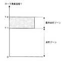
なお、このヒータ制御装置における定着加熱ローラの指定温度域は、たとえば設定温度T1を含む1〜5℃の範囲であることが好ましい。
以上のように構成された本実施の形態例のヒータ制御装置あるいは画像形成装置における動作を説明する。
【0040】
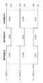
まず、制御回路40は画像形成装置の主電源の投入あるいは画像形成の際の必要に応じてメインヒータ11によって加熱される定着加熱ローラ(メインローラ)61の表面温度を温度センサ61sによって監視する(図4S1)。なお、制御回路40は、メインヒータ11のオン−オフ制御によって、定着加熱ローラ61の表面温度が指定温度域(図5のT1〜T2)になるように制御している。
【0041】
何らかの理由により定着加熱ローラ61の表面温度が指定温度域の下限T1未満になった場合(図4S2でYES)、メインヒータ11とサブヒータ12との両方、または、メインヒータ11の一方のみを点灯して温度低下を防止すべく、制御回路40は以下の制御を実行する。
【0042】
ここで、制御回路40は、サブヒータ12によって加熱される定着加熱ローラ(サブローラ)62の表面温度を温度センサ62sによって監視する(図4S3、S4)。
【0043】
この温度監視によって、
▲1▼定着加熱ローラ62の温度が所定の指定温度域内(T1〜T2)にあるときには、メインヒータ11とサブヒータ12とを直列接続してから点灯するよう制御する(図4S5)。
▲2▼定着加熱ローラ62の温度が所定の指定温度域未満(T1未満)になっているときは、メインヒータ11とサブヒータ12とを並列接続してから点灯するよう制御する(図4S6)。
▲3▼定着加熱ローラ62の温度が所定の指定温度域(T2)を超えているときには、サブヒータ12を点灯せずに、メインヒータ11のみを単独で点灯するよう制御する(図4S7)。
【0044】
以上のようにすることで、▲1▼の場合に複数のヒータを点灯させる際に、直列接続によって抵抗値が増し、温度が低く抵抗値が小さいサブヒータ12を点灯させる場合にも、突入電流が小さくなる。すなわち、発生する過大な電流を抑制し、当該ヒータと共通の電源系統に接続された他の照明機器等に発生するフリッカを抑制することができるようになる。また、▲2▼の場合には、低温状態を解消するため、並列接続により温度上昇を促す。また、▲3▼の場合には、サブヒータ12の点灯は不要であり、メインヒータ11のみで対処する。
【0045】
なお、以上の▲1▼で直列接続したメインヒータ11とサブヒータ12とは、一定時間経過後に、直列接続から並列接続に切り替えることで、十分な加熱を行うことが可能になる。この一定時間経過後であれば、ヒータが赤熱しており抵抗値が十分高くなっているので、並列接続状態に切り替えてもフリッカは軽減される。
【0046】
〈第2の実施の形態例〉
図6は、本発明のヒータ制御装置におけるヒータ点灯回路の第2の実施の形態例を示す回路構成図である。既に説明した図1と同一物には同一の番号を付してある。
【0047】
このヒータ点灯回路は、メインヒータ(ヒータ#1)11とサブヒータ(ヒータ#2)12が、3つのスイッチ素子21、22、23を介して、たとえば商用電源よりなる共通の交流電源10に接続されて構成されている。
【0048】
具体的には、まず、メインヒータ11とスイッチ素子21とが直列に交流電源10に接続される。そして、交流電源10とメインヒータ11との接続点a1と、スイッチ素子21と交流電源10との接続点a2との間に、スイッチ素子22、大電流制限素子としての抵抗33およびスイッチ素子23の直列回路が接続される。さらに、スイッチ素子22と抵抗33との接続点a3と、メインヒータ11とスイッチ素子21との接続点a4との間に、サブヒータ12が接続されている。
【0049】
また、3つのスイッチング素子21〜23は制御端子からの制御信号によって、オン/オフが切り替えられるように構成されており、制御回路40からの制御信号が各スイッチング素子の制御端子に供給されている。すなわち、スイッチ素子21〜23は、いずれも、たとえばトライアックなどの制御端子付きスイッチ素子よりなり、制御信号によってオン状態またはオフ状態となるよう各々が独立して制御されるものである。
【0050】
また、メインヒータ11およびサブヒータ12は、たとえばハロゲン白熱ランプなどのヒータランプより構成され、このヒータ点灯回路においては、メインヒータ11とサブヒータ12とは制御回路40により点灯・消灯の制御がなされる。
【0051】
これらのヒータ11、12の加熱対象は、図2に示すような同種の被加熱体(たとえば画像形成装置の定着部60における対向する定着加熱ローラ61,62)であることは、第1の実施の形態例と同様である。
【0052】
このヒータ点灯回路においては、スイッチ素子21およびスイッチ素子22を共にオフ状態とし、スイッチ素子23をオン状態とする(図7参照)ことにより、図8(a)のように、メインヒータ11とサブヒータ12と抵抗33とが直列接続状態となる。また、スイッチ素子21およびスイッチ素子22を共にオン状態とし、スイッチ素子23をオフ状態とする(図7参照)ことにより、図8(b)のようにメインヒータ11とサブヒータ12の両者が並列接続状態となる。このように直列接続状態〜並列接続状態〜直列接続状態と切り替えて点灯することにより、点灯時および消灯時の突入電流を小さく抑えることが可能になる。
【0053】
ところが、直列接続状態から並列接続状態に切り替わるタイミング、および、並列接続状態から直列接続状態に切り替わる瞬間において、スイッチ素子22のオンとスイッチ素子23のオンが重なることがありうる。その場合には、スイッチ素子22とスイッチ素子23とで電源10に対する短絡回路を構成することになる。このため、従来はデッドショートを生じて大電流が流れていた。ところが、本実施の形態例では、交流電源に対して短絡回路を形成する経路のいずれかの位置に大電流制限素子としての抵抗33が配置されているため、直列接続状態と並列接続状態との間で切り替え可能な複数のヒータを有する場合に、当該複数のヒータの接続状態を切り替える際に、短絡回路が形成されたとしても抵抗33によりデッドショートによるスイッチ素子の破壊が防止され(図8(c)参照)、動作の信頼性の高いヒータ制御装置および画像形成装置を実現できる。
【0054】
なお、従来のデッドショート発生時には、大電流が流れることにより、スイッチ素子22かスイッチ素子23が破壊されていた。ここで、スイッチ素子22が破壊されると、複数のヒータを並列接続することができず、低温異常が発生して正常な画像形成ができなくなる。一方、スイッチ素子23が破壊されると、直列制御ができず、ちらつきの発生の原因となる。ところが、本実施の形態例によれば、このような不具合は解消される。
【0055】
また、この実施の形態例のように大電流制限素子としての抵抗33を配置することで、全スイッチ素子を一定時間一斉にオフするような面倒な制御は不要になる。また、大電流制限素子に抵抗を用いることで、複雑なスイッチの制御や高価な素子を用いることなく、簡易な構成で廉価に所望の目的を達成する装置を構成することが可能になる。
【0056】
〈第3の実施の形態例〉
図9は、本発明のヒータ制御装置におけるヒータ点灯回路の第3の実施の形態例を示す回路構成図である。既に説明した図1や図6と同一物には同一の番号を付してある。
【0057】
このヒータ点灯回路は、メインヒータ(ヒータ#1)11とサブヒータ(ヒータ#2)12が、3つのスイッチ素子21、22、23を介して、たとえば商用電源よりなる共通の交流電源10に接続されて構成されている。
【0058】
具体的には、まず、メインヒータ11とスイッチ素子21とが直列に交流電源10に接続される。そして、交流電源10とメインヒータ11との接続点a1と、スイッチ素子21と交流電源10との接続点a2との間に、スイッチ素子22、大電流制限素子としての抵抗33およびスイッチ素子23の直列回路が接続される。さらに、スイッチ素子22と抵抗33との接続点a3と、メインヒータ11とスイッチ素子21との接続点a4との間に、サブヒータ12が接続されている。
【0059】
また、3つのスイッチング素子21〜23は制御端子からの制御信号によって、オン/オフが切り替えられるように構成されており、制御回路40からの制御信号が各スイッチング素子の制御端子に供給されている。すなわち、スイッチ素子21〜23は、いずれも、たとえばトライアックなどの制御端子付きスイッチ素子よりなり、制御信号によってオン状態またはオフ状態となるよう各々が独立して制御されるものである。
【0060】
これらのヒータ11、12の加熱対象は、図2に示すような同種の被加熱体(たとえば画像形成装置の定着部60における対向する定着加熱ローラ61,62)であることは、第1の実施の形態例と同様である。
【0061】
なお、メインヒータ11が加熱する定着加熱ローラ61近傍には温度センサ61sが配置され、メインヒータ12が加熱する定着加熱ローラ62近傍には温度センサ62sが配置されている。そして、被加熱体の温度を検知する温度センサ61s,62sからの温度データ信号に基づいて、制御回路40が各スイッチ素子の状態を制御するように構成されている。
【0062】
このようなヒータ制御装置においては、画像形成装置の主電源が投入された後の状態に応じて、メインヒータ11およびサブヒータ12が種々の態様で各々独立して制御される。たとえば被加熱体の稼動中においては、被加熱体の温度が指定温度域内に維持されるよう、温度センサにより検知される被加熱体の温度に応じて、メインヒータ11とサブヒータ12を共に点灯または消灯させ、あるいはメインヒータ11とサブヒータ12のうち、いずれか一方を点灯または消灯させる態様で、メインヒータ11とサブヒータ12がオン−オフ制御される。
【0063】
以上のように構成された本実施の形態例のヒータ制御装置あるいは画像形成装置における動作としては、図4のフローチャートで説明した第1の実施の形態例と同様に、温度監視によって、
▲1▼定着加熱ローラ62の温度が所定の指定温度域内(T1〜T2)にあるときには、メインヒータ11とサブヒータ12とを直列接続してから点灯するよう制御する(図4S5)。
▲2▼定着加熱ローラ62の温度が所定の指定温度域未満(T1未満)になっているときは、メインヒータ11とサブヒータ12とを並列接続してから点灯するよう制御する(図4S6)。
▲3▼定着加熱ローラ62の温度が所定の指定温度域(T2)を超えているときには、サブヒータ12を点灯せずに、メインヒータ11のみを単独で点灯するよう制御する(図4S7)。
【0064】
以上のようにすることで、▲1▼の場合に複数のヒータを点灯させる際に、直列接続によって抵抗値が増し、温度が低く抵抗値が小さいサブヒータ12を点灯させる場合にも、突入電流が小さくなる。すなわち、発生する過大な電流を抑制し、当該ヒータと共通の電源系統に接続された他の照明機器等に発生するフリッカを抑制することができるようになる。また、▲2▼の場合には、低温状態を解消するため、並列接続により温度上昇を促す。また、▲3▼の場合には、サブヒータ12の点灯は不要であり、メインヒータ11のみで対処する。なお、以上の▲1▼で直列接続したメインヒータ11とサブヒータ12とは、一定時間経過後に、直列接続から並列接続に切り替えることで、十分な加熱を行うことが可能になる。この一定時間経過後であれば、ヒータが赤熱しており抵抗値が十分高くなっているので、並列接続状態に切り替えてもフリッカは軽減される。
【0065】
そして、以上のような直列接続状態と並列接続状態との切り替えにおいて、点灯時や消灯時の突入電流を小さく抑えることが可能になるが、直列接続状態から並列接続状態に切り替わるタイミング、および、並列接続状態から直列接続状態に切り替わる瞬間において、スイッチ素子22のオンとスイッチ素子23のオンが重なることがありうる。その場合には、スイッチ素子22とスイッチ素子23とで電源10に対する短絡回路を構成することになるが、本実施の形態例では、交流電源に対して短絡回路を形成する経路のいずれかの位置に大電流制限素子としての抵抗33が配置されているため、短絡回路が形成されたとしても抵抗33によりデッドショートによるスイッチ素子の破壊が防止され(図8(c)参照)、動作の信頼性の高いヒータ制御装置および画像形成装置を実現できる。
【0066】
なお、従来のデッドショート発生時には、大電流が流れることにより、スイッチ素子22かスイッチ素子23が破壊されていた。ここで、スイッチ素子22が破壊されると、複数のヒータを並列接続することができず、低温異常が発生して正常な画像形成ができなくなる。一方、スイッチ素子23が破壊されると、直列制御ができず、ちらつきの発生の原因となる。ところが、本実施の形態例によれば、このような不具合は解消される。
【0067】
また、この実施の形態例のように大電流制限素子としての抵抗33を配置することで、全スイッチ素子を一定時間一斉にオフするような面倒な制御は不要になる。また、大電流制限素子に抵抗を用いることで、複雑なスイッチの制御や高価な素子を用いることなく、簡易な構成で廉価に所望の目的を達成する装置を構成することが可能になる。
【0068】
【実施例】
〈実施例1〉
出力電力が900Wのメインヒータ11と、出力電力が300Wのサブヒータ12の2つのハロゲン白熱ランプが定着加熱ローラ61,62の加熱源としてそれぞれ設けられた定着装置60を備えた画像形成装置を用い、定着加熱ローラの設定温度を207℃、指定温度域を205〜208℃に設定した。
【0069】
そして、メインヒータ11とサブヒータ12が直列接続状態に保持される時間を、加熱定着ローラ61,62の温度が加熱開始前の温度より1℃上昇するまでに要する時間に設定すると共に、メインヒータ11とサブヒータ12が直列接続状態に保持される時間を3secに設定して、定着装置60の定着加熱ローラ61,62の温度が指定温度域内に維持されるようメインヒータ11とサブヒータ12がオン−オフ制御されている状態において、メインヒータ11とサブヒータ12を点灯させたときに流れる突入電流のピーク値を測定したところ、突入電流が24Aであった。
【0070】
また、電圧変動量により規定されるコピー動作中のフリッカ値(短期間フリッカ値)および電圧変動の発生頻度により規定されるスタンバイ中のフリッカ値(長期間フリッカ値)をフリッカ測定装置「フリッカーメーター」を用いて測定したところ、短期間フリッカ値は0.88、長期間フリッカ値は0.63であり、いずれも、規定された範囲を満足するものであった。
【0071】
〈比較例1〉
実施例1と同様の画像形成装置において、メインヒータ11とサブヒータ12を直列接続状態を経由させずに点灯させることにより、定着装置60における定着加熱ローラ61,62の温度が指定温度域内に維持されるようメインヒータ11とサブヒータ12がオン−オフ制御されている状態において、メインヒータ11とサブヒータ12を点灯させたときに流れる突入電流のピーク値を測定したところ、突入電流が55Aであった。
【0072】
また、短期間フリッカ値および長期間フリッカ値を測定したところ、短期間フリッカ値は2.0、長期間フリッカ値は1.11であり、いずれも、規定された範囲を満足しないものであった。
【0073】
以上の結果から、メインヒータとサブヒータが並列接続状態で点灯されるときに、直列接続状態を経由することにより、突入電流が抑制される結果、これらのヒータと共通の電源系統に接続された他の照明機器等に発生するフリッカを抑制することができ、従って、出力電力の合計値が大きいヒータを加熱源として備えた定着装置を有する場合であっても、フリッカ規格を満足させることができることがわかる。
【0074】
〈実施例2〉
出力電力が900Wのメインヒータ11と、出力電力が300Wのサブヒータ12の2つのハロゲン白熱ランプが定着加熱ローラ61,62の加熱源として設けられ、大電流制限素子としての抵抗33には1.8Ω(20W)のセメント抵抗を用いた定着装置60を備えた画像形成装置を用いた。
【0075】
そして、メインヒータ11とサブヒータ12とが直列接続状態と並列接続状態とに切り替わるようにして、定着装置60の定着加熱ローラ61,62の温度が指定温度域内に維持されるようメインヒータ11とサブヒータ12がオン−オフ制御されるように設定した。
【0076】
この状態において、スイッチ素子22とスイッチ素子23とのオン期間が重なった場合に流れる電流のピーク値を測定したところ、ピークで180Aであり、安全な範囲であった。このため、スイッチ素子の破壊を防止できる。なお、ヒータの並列接続状態では抵抗は全く作用しない。
【0077】
〈比較例2〉
実施例2と同様の画像形成装置において、メインヒータ11とサブヒータ12とが直列接続状態と並列接続状態とに切り替わるようにして、スイッチ素子22とスイッチ素子23とのオン期間が重なった場合には測定できない程の大電流(抵抗がほぼ0であるため、理論的には無限大)が瞬間的に流れ、安全な範囲を逸脱していた。このため、電源に悪影響を与えると共に、スイッチ素子の破壊を招くことになる。
【0078】
以上の結果から、メインヒータとサブヒータが直列接続状態と並列接続状態とで点灯されるときに、大電流制限素子としての抵抗33を配置することで、短絡回路が形成されたとしてもデッドショートによるスイッチ素子の破壊が防止される。このため、動作の信頼性の高いヒータ制御装置および画像形成装置を実現できることが分かった。
【0079】
【発明の効果】
以上説明したように本発明によれば、以下のような効果が得られる。
(1)複数のヒータを点灯させる際に、ローラの温度に応じて直列接続とすることで抵抗値が増し、突入電流が小さくなる。すなわち、発生する過大な電流を抑制し、当該ヒータと共通の電源系統に接続された他の照明機器等に発生するフリッカを抑制することができるようになる。
【0080】
(2)複数のヒータの接続状態を切り替える複数のスイッチ素子の状態によって、交流電源に対して短絡回路を形成する経路の位置に大電流制限素子が配置されているため、直列接続状態と並列接続状態との間で切り替え可能な複数のヒータを有する場合に、当該複数のヒータの接続状態を切り替える際に、短絡回路が形成されたとしてもデッドショートによるスイッチ素子の破壊が防止される。このため、動作の信頼性の高いヒータ制御装置および画像形成装置を実現できる。
【0081】
(3)複数のヒータを点灯させる際に、ローラの温度に応じて直列接続とすることで抵抗値が増し、発生する過大な電流を抑制し、当該ヒータと共通の電源系統に接続された他の照明機器等に発生するフリッカを抑制することができると共に、スイッチ素子の状態によって交流電源に対して短絡回路を形成する経路の位置に大電流制限素子を配置することで、ヒータの直列接続状態と並列接続状態との間で切り替える際に、短絡回路が形成されたとしてもデッドショートによるスイッチ素子の破壊が防止して、動作の信頼性の高いヒータ制御装置および画像形成装置を実現できる。
【図面の簡単な説明】
【図1】本発明の第1の実施の形態例のヒータ制御装置におけるヒータ点灯回路の一例を示す回路構成図である。
【図2】本発明の第1の実施の形態例の画像形成装置の主要部の構成を示す構成図である。
【図3】本発明の第1の実施の形態例のヒータ制御装置におけるヒータの接続状態の一例を示す回路構成図である。
【図4】本発明の第1の実施の形態例の動作状態を説明するフローチャートである。
【図5】本発明の第1の実施の形態例のヒータ制御に関する説明図である。
【図6】本発明の第2の実施の形態例のヒータ制御装置におけるヒータ点灯回路の一例を示す回路構成図である。
【図7】本発明の第2の実施の形態例の動作状態を説明するタイムチャートである。
【図8】本発明の第2の実施の形態例のヒータ制御装置におけるヒータの接続状態の一例を示す回路構成図である。
【図9】本発明の第3の実施の形態例のヒータ制御装置におけるヒータ点灯回路の一例を示す回路構成図である。
【符号の説明】
10 交流電源
11 メインヒータ
12 サブヒータ
21、22、23 スイッチ素子
60 定着器
61,62 定着加熱ローラ
61s,62s 温度センサ[0001]
BACKGROUND OF THE INVENTION
The present invention relates to a heater control device that controls a heater as a heating source used for fixing image formation, and an image forming apparatus using the heater control device.
[0002]
[Prior art]
In general, in an electrophotographic image forming apparatus, in order to thermally fix a toner image transferred to one surface of an image support such as transfer paper to the image support, fixing heating in contact with the one surface of the image support. 2. Description of the Related Art A fixing device including a roller and a pressure roller arranged so as to be pressed against the fixing heating roller is widely used.
[0003]
In a certain type of fixing device, a heater lamp such as a halogen lamp (hereinafter simply referred to as “heater”) is provided in each of the upper and lower rollers as a heating source of the fixing heating roller. Is configured such that its lighting state is independently controlled on and off.
[0004]
Thus, the reason why the plurality of heaters are provided is that, for example, the temperature distribution of the fixing heating roller is referred to as a preset temperature range (hereinafter referred to as “designated temperature range”) regardless of the difference in the size of the image support. ) And the rise time of the temperature of the fixing heating roller can be shortened.
[0005]
[Problems to be solved by the invention]
<First issue>
However, in the above-described fixing device, when a plurality of heaters are lit, an inrush current flows through the heater lighting circuit as soon as the heaters are energized. Due to this inrush current, voltage fluctuation occurs in the lamp line to which the image forming apparatus is connected.
[0006]
As a result of such voltage fluctuations in the power line, there is a problem that flicker (“flickering feeling felt by humans”) occurs in lighting equipment connected to a power supply system common to the image forming apparatus. It is necessary to suppress the degree within a prescribed range (flicker standard). For example, in an image forming apparatus, a flicker value (short-term flicker value) during a copy operation defined by a voltage fluctuation amount is 1 or less, and a flicker value during standby (long-term flicker value) defined by the frequency of occurrence of voltage fluctuations. ) Is regulated to 0.65 or less.
[0007]
However, in the fixing device as described above, it has been found that both the short-term flicker value and the long-term flicker value are not suppressed within the specified range. Such a problem becomes prominent particularly when a heater having a high output power is used.
[0008]
That is, in the fixing device having the above-described configuration, when a plurality of heaters that are turned off are turned on in a parallel connection state, a large inrush current is generated in the heater lighting circuit, thereby configuring the image forming apparatus. There was a problem of adversely affecting the equipment.
[0009]
Therefore, in a heater lighting circuit configured by electrically connecting a plurality of heaters to a common AC power source via a plurality of switch elements, each heater is in a parallel connection state at the time of use. Although it is conceivable that the heaters are once connected in series and then switched to the parallel connection state, the conditions such as the conditions under which the connection state should be switched have not been considered.
[0010]
<Second problem>
Further, as described above, in a heater lighting circuit configured by electrically connecting a plurality of heaters to a common AC power source via a plurality of switch elements, each heater is in a parallel connection state when used, but is lit. In the case of a heater lighting circuit configured to switch each heater to a series connection state and then switch to a parallel connection state, for example, when switching the heater connection state from a series connection state to a parallel connection state, for example. Since switching of the state of each switch element is performed at the same time, there is a possibility that a short circuit is formed by the switch element that is turned on with respect to the AC power supply and a dead short circuit occurs.
[0011]
In such a case, a control that turns off all the switch elements all at once for a certain period of time can be considered, but the control becomes troublesome, and it is expected that a problem that the temperature of the heater is lowered due to the off period also occurs.
[0012]
<Object of invention>
The present invention has been made to solve the first problem as described above, and its purpose is to suppress an excessive current generated when a plurality of heaters are turned on, and to share the same with the heaters. An object of the present invention is to provide a heater control device and an image forming apparatus capable of suppressing flicker generated in other lighting devices connected to a power supply system.
[0013]
Further, the present invention has been made based on the second problem as described above, and the object is to have a plurality of heaters that can be switched between a serial connection state and a parallel connection state. An object of the present invention is to provide a heater control device and an image forming apparatus with high operation reliability by preventing a switch element from being broken due to a dead short when switching the connection state of a plurality of heaters.
[0014]
[Means for Solving the Problems]
The present invention for solving the above problems is as described below.
(1) According to the first aspect of the present invention, a plurality of switch elements for switching power supply from a common power source are connected to a common power source via the plurality of switch elements, and each is incorporated in a roller to increase the temperature. A plurality of heaters whose resistance value also increases, and a switching control means for controlling the plurality of heaters so as to be switchable between a series connection state and a parallel connection state by controlling the state of each switch element; A temperature control means for detecting the temperature of the roller heated by the heater, wherein the plurality of heaters are a high-power main heater and a low-power sub-heater, and the switching control means is The main heaterWhen the temperature of the roller heated by theWhen the temperature of the roller heated by the sub-heater is within a predetermined specified temperature range, the sub-heater and the main heater are controlled to be lit after being connected in series, and are controlled to be switched to parallel connection after a certain time. And the main heaterWhen the temperature of the roller heated by theWhen the temperature of the roller heated by the sub-heater is lower than a predetermined designated temperature range, the sub-heater and the main heater are connected in parallel and then controlled to light up, and the main heaterWhen the temperature of the roller heated by theWhen the temperature of the roller heated by the sub-heater exceeds a predetermined designated temperature range, the main heater is controlled to be lit alone.
[0015]
The invention according to
[0016]
In these inventions, when trying to turn on one heater,
[1]When the temperature of the roller heated by the other heater is within the specified temperature range, control to turn on after connecting in series with the other heater,
[2]When the temperature of the roller heated by the other heater is lower than a predetermined designated temperature range, control is performed so that one heater and the other heater are connected in parallel and then lit.
[3]When the temperature of the roller heated by the other heater exceeds a specified temperature range, control is performed so that only one heater is turned on without being connected to the other heater.
[0017]
By doing so,[1]In the case of turning on multiple heaters, the resistance value increases due to series connection, the temperature is low and the resistance value is low.smallInrush current is also reduced when the heater is turned on. That is, an excessive current generated can be suppressed, and flicker generated in other lighting devices connected to the power supply system common to the heater can be suppressed. Also,[2]In this case, in order to eliminate the low temperature state, the temperature rise is promoted by parallel connection. Also,[3]In this case, it is not necessary to turn on the other heater, and only one heater is used.
[0018]
That is, an excessive current generated can be suppressed, and flicker generated in other lighting devices connected to a common power supply system with the heater can be suppressed..
[0019]
Claims3In the described invention, a plurality of switch elements for switching power supply from a common power source and a plurality of switch elements are connected to a common power source via each of the plurality of switch elements, and each is incorporated in a roller, and the resistance value increases as the temperature rises. A plurality of heaters, a switching control means for controlling the plurality of heaters so as to be switchable between a series connection state and a parallel connection state, and states of the plurality of switch elements; The position of the path that forms a short circuit with respect to the AC power supply, and is connected in series when the plurality of heaters are connected in series, and is not connected when the plurality of heaters are connected in parallel. And a large current limiting element disposed in the image forming apparatus.
[0020]
In the above case, the large current limiting element is preferably a resistor.
In these inventions, a path for forming a short circuit with respect to the AC power supply is determined depending on the states of the plurality of switch elements.Position, connected in series when multiple heaters are connected in series, not connected when multiple heaters are connected in parallelSince a large current limiting element is arranged at a position, when a plurality of heaters that can be switched between a series connection state and a parallel connection state are provided, a short circuit is generated when switching the connection state of the plurality of heaters. Even if formed, destruction of the switch element due to a dead short is prevented. For this reason, a heater control device and an image forming apparatus with high operation reliability can be realized.
[0021]
In addition, by using a resistor for the large current limiting element, it is possible to configure a device that achieves a desired object at a low cost with a simple configuration without using complicated switch control or expensive elements.
[0022]
(3) Claim5In the described invention, a plurality of switch elements for switching power supply from a common power source and a plurality of switch elements are connected to a common power source via each of the plurality of switch elements, and each is incorporated in a roller, and the resistance value increases as the temperature rises. A plurality of heaters, switching control means for controlling the plurality of heaters so as to be switchable between a series connection state and a parallel connection state, and a roller heated by each heater. A heater comprising: temperature detection means for detecting the temperature of the current source; and a large current limiting element disposed at any position in a path that forms a short circuit with respect to the AC power supply according to the states of the plurality of switch elements. The plurality of heaters are a high-power main heater and a low-power sub-heater, and the switching control means is the control device. NhitaWhen the temperature of the roller heated by theWhen the temperature of the roller heated by the sub-heater is within a predetermined specified temperature range, the sub-heater and the main heater are controlled to be lit after being connected in series, and are controlled to be switched to parallel connection after a certain time. And the main heaterWhen the temperature of the roller heated by theWhen the temperature of the roller heated by the sub-heater is lower than a predetermined designated temperature range, the sub-heater and the main heater are connected in parallel and then controlled to light up, and the main heaterWhen the temperature of the roller heated by theWhen the temperature of the roller heated by the sub-heater exceeds a predetermined designated temperature range, the main heater is controlled to be lit alone.
[0023]
In addition, a plurality of switch elements that switch power supply from a common power source, and a plurality of heaters that are connected to a common power source via the plurality of switch elements, each of which is built in a roller and whose resistance value increases as the temperature rises And a switching control means for controlling the state of each of the switch elements so that the plurality of heaters can be switched between a serial connection state and a parallel connection state, and a temperature of a roller heated by each heater. An image for performing heater control, comprising temperature detecting means for detecting, and a large current limiting element arranged at any position on a path that forms a short circuit with respect to the AC power supply according to the states of the plurality of switch elements. The plurality of heaters are a high-power main heater and a low-power sub-heater, and the switching control means The main heaterWhen the temperature of the roller heated by theWhen the temperature of the roller heated by the sub-heater is within a predetermined specified temperature range, the sub-heater and the main heater are controlled to be lit after being connected in series, and are controlled to be switched to parallel connection after a certain time. And the main heaterWhen the temperature of the roller heated by theWhen the temperature of the roller heated by the sub-heater is lower than a predetermined designated temperature range, the sub-heater and the main heater are connected in parallel and then controlled to light up, and the main heaterWhen the temperature of the roller heated by theThe image forming apparatus is characterized in that when the temperature of the roller heated by the sub-heater exceeds a specified temperature range, the main heater is controlled to be lit alone.
[0024]
The large current limiting element described above is preferably a resistor. In these inventions, when trying to turn on one heater,
[1]When the temperature of the roller heated by the other heater is within a predetermined specified temperature range, control to turn on after connecting in series with the other heater,
[2]When the temperature of the roller heated by the other heater is lower than a predetermined designated temperature range, control is performed so that one heater and the other heater are connected in parallel and then lit.
[Three]When the temperature of the roller heated by the other heater exceeds a specified temperature range, control is performed so that only one heater is turned on without being connected to the other heater.
[0025]
By doing so,[1]In the case of turning on multiple heaters, the resistance value increases due to series connection, the temperature is low and the resistance value is low.smallInrush current is also reduced when the heater is turned on. That is, an excessive current generated can be suppressed, and flicker generated in other lighting devices connected to the power supply system common to the heater can be suppressed. Also,[2]In this case, in order to eliminate the low temperature state, the temperature rise is promoted by parallel connection. Also,[Three]In this case, it is not necessary to turn on the other heater, and only one heater is used.
[0026]
In these inventions, since the large current limiting element is arranged at any position on the path that forms a short circuit with respect to the AC power supply depending on the state of the plurality of switch elements, the series connection state and the parallel connection state In the case of having a plurality of heaters that can be switched to each other, even when a short circuit is formed when switching the connection state of the plurality of heaters, destruction of the switch element due to a dead short is prevented. For this reason, a heater control device and an image forming apparatus with high operation reliability can be realized.
[0027]
In addition, by using a resistor for the large current limiting element, it is possible to configure a device that achieves a desired object at a low cost with a simple configuration without using complicated switch control or expensive elements.
[0028]
DETAILED DESCRIPTION OF THE INVENTION
Hereinafter, embodiments of the present invention will be described in detail with reference to the drawings.
<First Embodiment>
FIG. 1 is a circuit configuration diagram showing a first embodiment of a heater lighting circuit in the heater control apparatus of the present invention.
[0029]
In this heater lighting circuit, a main heater (heater # 1) 11 and a sub heater (heater # 2) 12 are connected to a common
[0030]
Specifically, first, the
[0031]
The three
[0032]
The switch element is not limited to a triac or the like, and various elements can be used. The
[0033]
Further, the
[0034]
The heating targets of these
[0035]
In this case, the
A
[0036]
In this heater lighting circuit, both the
[0037]
That is, in the heater lighting circuit as described above, the
[0038]
In such a heater control device, the
[0039]
The specified temperature range of the fixing heating roller in this heater control device is preferably in the range of 1 to 5 ° C. including the set temperature T1, for example.
The operation of the heater control apparatus or image forming apparatus of the present embodiment configured as described above will be described.
[0040]
First, the
[0041]
If for some reason the surface temperature of the fixing
[0042]
Here, the
[0043]
With this temperature monitoring,
(1) When the temperature of the fixing
{Circle around (2)} When the temperature of the fixing
(3) When the temperature of the fixing
[0044]
As described above, when the plurality of heaters are turned on in the case of (1), the inrush current is increased even when the resistance value is increased by the series connection and the
[0045]
In addition, the
[0046]
<Second Embodiment>
FIG. 6 is a circuit configuration diagram showing a second embodiment of the heater lighting circuit in the heater control apparatus of the present invention. The same components as those in FIG. 1 already described are assigned the same reference numerals.
[0047]
In this heater lighting circuit, a main heater (heater # 1) 11 and a sub heater (heater # 2) 12 are connected to a common
[0048]
Specifically, first, the
[0049]
The three
[0050]
Further, the
[0051]
The heating target of these
[0052]
In this heater lighting circuit, both the
[0053]
However, at the timing of switching from the serial connection state to the parallel connection state, and at the moment of switching from the parallel connection state to the series connection state, the
[0054]
When a conventional dead short occurs, the
[0055]
Further, by arranging the
[0056]
<Third embodiment>
FIG. 9 is a circuit configuration diagram showing a third embodiment of the heater lighting circuit in the heater control device of the present invention. The same number is attached | subjected to the same thing as FIG.1 and FIG.6 already demonstrated.
[0057]
In this heater lighting circuit, a main heater (heater # 1) 11 and a sub heater (heater # 2) 12 are connected to a common
[0058]
Specifically, first, the
[0059]
The three
[0060]
The heating target of these
[0061]
A
[0062]
In such a heater control device, the
[0063]
As the operation of the heater control apparatus or image forming apparatus of the present embodiment configured as described above, as in the first embodiment described with reference to the flowchart of FIG.
(1) When the temperature of the fixing
{Circle around (2)} When the temperature of the fixing
(3) When the temperature of the fixing
[0064]
In this way, when a plurality of heaters are turned on in the case of (1), the inrush current is increased even when the resistance value is increased by series connection and the sub-heater 12 having a low temperature and a small resistance value is turned on. Get smaller. That is, an excessive current generated can be suppressed, and flicker generated in other lighting devices connected to the power supply system common to the heater can be suppressed. In the case of (2), in order to eliminate the low temperature state, the temperature rise is promoted by parallel connection. In the case of (3), it is not necessary to turn on the sub-heater 12, and only the
[0065]
And, in switching between the series connection state and the parallel connection state as described above, it becomes possible to suppress the inrush current at the time of lighting or extinguishing, but the timing of switching from the series connection state to the parallel connection state, and the parallel At the moment when the connection state is switched to the series connection state, the
[0066]
When a conventional dead short occurs, the
[0067]
Further, by arranging the
[0068]
【Example】
<Example 1>
An image forming apparatus provided with a fixing
[0069]
The time during which the
[0070]
Further, the flicker value “short-term flicker value” during the copying operation defined by the voltage fluctuation amount and the flicker value during standby (long-term flicker value) defined by the frequency of occurrence of the voltage fluctuation are the flicker measuring device “flicker meter”. The short-term flicker value was 0.88, and the long-term flicker value was 0.63, both satisfying the specified range.
[0071]
<Comparative example 1>
In the image forming apparatus similar to that of the first embodiment, the temperature of the fixing
[0072]
Further, when the short-term flicker value and the long-term flicker value were measured, the short-term flicker value was 2.0 and the long-term flicker value was 1.11, both of which did not satisfy the specified range. .
[0073]
From the above results, when the main heater and the sub-heater are lit in the parallel connection state, the inrush current is suppressed by going through the series connection state. Flicker generated in the lighting equipment or the like can be suppressed. Therefore, even when a fixing device having a heater with a large total output power as a heating source is provided, the flicker standard can be satisfied. Recognize.
[0074]
<Example 2>
Two halogen incandescent lamps, a
[0075]
Then, the
[0076]
In this state, when the peak value of the current that flows when the ON period of the
[0077]
<Comparative example 2>
In the same image forming apparatus as in the second embodiment, when the
[0078]
From the above results, when the main heater and the sub-heater are lit in the series connection state and the parallel connection state, the
[0079]
【The invention's effect】
As described above, according to the present invention, the following effects can be obtained.
(1) When turning on a plurality of heaters, the resistance value is increased by connecting them in series according to the temperature of the roller, and the inrush current is reduced. That is, an excessive current generated can be suppressed, and flicker generated in other lighting devices connected to the power supply system common to the heater can be suppressed.
[0080]
(2) Since the large current limiting element is arranged at the position of the path that forms the short circuit with respect to the AC power supply depending on the state of the plurality of switch elements that switch the connection state of the plurality of heaters, the series connection state and the parallel connection In the case of having a plurality of heaters that can be switched between states, even when a short circuit is formed when the connection state of the plurality of heaters is switched, destruction of the switch element due to a dead short is prevented. For this reason, a heater control device and an image forming apparatus with high operation reliability can be realized.
[0081]
(3) When turning on a plurality of heaters, the resistance value is increased by connecting them in series according to the temperature of the roller, the excessive current generated is suppressed, and other heaters connected to the power supply system common to the heaters Flickers that occur in lighting equipment, etc. can be suppressed, and by arranging a large current limiting element at the position of the path that forms a short circuit with respect to the AC power supply depending on the state of the switch element, the heater is connected in series When switching between a parallel connection state and a parallel connection state, even if a short circuit is formed, the switch element can be prevented from being destroyed by a dead short, and a heater control device and an image forming apparatus with high operation reliability can be realized.
[Brief description of the drawings]
FIG. 1 is a circuit configuration diagram showing an example of a heater lighting circuit in a heater control apparatus according to a first embodiment of the present invention.
FIG. 2 is a configuration diagram illustrating a configuration of a main part of the image forming apparatus according to the first exemplary embodiment of the present invention.
FIG. 3 is a circuit configuration diagram showing an example of a heater connection state in the heater control apparatus according to the first embodiment of the present invention.
FIG. 4 is a flowchart illustrating an operation state of the first exemplary embodiment of the present invention.
FIG. 5 is an explanatory diagram related to heater control according to the first embodiment of the present invention.
FIG. 6 is a circuit configuration diagram showing an example of a heater lighting circuit in the heater control apparatus according to the second embodiment of the present invention.
FIG. 7 is a time chart for explaining an operation state of the second exemplary embodiment of the present invention.
FIG. 8 is a circuit configuration diagram showing an example of a heater connection state in the heater control apparatus according to the second embodiment of the present invention.
FIG. 9 is a circuit configuration diagram showing an example of a heater lighting circuit in a heater control apparatus according to a third embodiment of the present invention.
[Explanation of symbols]
10 AC power supply
11 Main heater
12 Sub-heater
21, 22, 23 Switch element
60 Fixing device
61, 62 Fixing heating roller
61s, 62s temperature sensor
Claims (8)
Translated fromJapanese複数のスイッチ素子を介して共通の電源に接続され、それぞれがローラに内蔵され、温度上昇に伴い抵抗値も上昇する複数のヒータと、
前記各スイッチ素子の状態を制御することにより、前記複数のヒータについて直列接続状態と並列接続状態との間で切り替え可能に制御するスイッチング制御手段と、
各ヒータにより加熱されるローラの温度を検知する温度検知手段と、
を備えたヒータ制御装置であって、
前記複数のヒータは、大電力のメインヒータと小電力のサブヒータであり、
前記スイッチング制御手段は、
前記メインヒータにより加熱されるローラの温度が所定の指定温度域未満のときであって前記サブヒータにより加熱されるローラの温度が所定の指定温度域内にあるときには、該サブヒータと前記メインヒータとを直列接続してから点灯するよう制御すると共に一定時間後に並列接続に切り替えて点灯するよう制御し、
前記メインヒータにより加熱されるローラの温度が所定の指定温度域未満のときであって前記サブヒータにより加熱されるローラの温度が所定の指定温度域未満のときは、該サブヒータと前記メインヒータとを並列接続してから点灯するよう制御し、
前記メインヒータにより加熱されるローラの温度が所定の指定温度域未満のときであって前記サブヒータにより加熱されるローラの温度が所定の指定温度域を超えているときには、前記メインヒータを単独で点灯するよう制御する、
ことを特徴とするヒータ制御装置。A plurality of switch elements for switching power supply from a common power source;
A plurality of heaters that are connected to a common power source via a plurality of switch elements, each of which is built in a roller, and whose resistance value increases as the temperature rises;
Switching control means for controlling the switch elements so as to be switchable between a series connection state and a parallel connection state for the plurality of heaters;
Temperature detecting means for detecting the temperature of the roller heated by each heater;
A heater control device comprising:
The plurality of heaters are a high-power main heater and a low-power sub-heater,
The switching control means includes
Whenthe temperature of the roller heated by the main heateris lowerthan a predetermined specified temperature range and the temperature of the roller heated by the sub heater is within a predetermined specified temperature range, the sub heater and the main heater are connected in series. Control to turn on after connecting and control to turn on and switch to parallel connection after a certain time,
Whenthe temperature of the roller heated by the main heateris lower than a predetermined specified temperature range and the temperature of the roller heated by the sub heater is lower than a predetermined specified temperature range, the sub heater and the main heater are Control to turn on after connecting in parallel,
Whenthe temperature of the roller heated by the main heateris lowerthan a predetermined specified temperature range and the temperature of the roller heated by the sub heater exceeds a predetermined specified temperature range, the main heater is lit alone. To control,
The heater control apparatus characterized by the above-mentioned.
複数のスイッチ素子を介して共通の電源に接続され、それぞれがローラに内蔵され、温度上昇に伴い抵抗値も上昇する複数のヒータと、
前記各スイッチ素子の状態を制御することにより、前記複数のヒータについて直列接続状態と並列接続状態との間で切り替え可能に制御するスイッチング制御手段と、
各ヒータにより加熱されるローラの温度を検知する温度検知手段と、
を備えヒータ制御を行う画像形成装置であって、
前記複数のヒータは、大電力のメインヒータと小電力のサブヒータであり、
前記スイッチング制御手段は、
前記メインヒータにより加熱されるローラの温度が所定の指定温度域未満のときであって前記サブヒータにより加熱されるローラの温度が所定の指定温度域内にあるときには、該サブヒータと前記メインヒータとを直列接続してから点灯するよう制御すると共に一定時間後に並列接続に切り替えて点灯するよう制御し、
前記メインヒータにより加熱されるローラの温度が所定の指定温度域未満のときであって前記サブヒータにより加熱されるローラの温度が所定の指定温度域未満のときは、該サブヒータと前記メインヒータとを並列接続してから点灯するよう制御し、
前記メインヒータにより加熱されるローラの温度が所定の指定温度域未満のときであって前記サブヒータにより加熱されるローラの温度が所定の指定温度域を超えているときには、前記メインヒータを単独で点灯するよう制御する、
ことを特徴とする画像形成装置。A plurality of switch elements for switching power supply from a common power source;
A plurality of heaters that are connected to a common power source via a plurality of switch elements, each of which is built in a roller, and whose resistance value increases as the temperature rises;
Switching control means for controlling the switch elements so as to be switchable between a series connection state and a parallel connection state for the plurality of heaters;
Temperature detecting means for detecting the temperature of the roller heated by each heater;
An image forming apparatus that performs heater control,
The plurality of heaters are a high-power main heater and a low-power sub-heater,
The switching control means includes
Whenthe temperature of the roller heated by the main heateris lowerthan a predetermined specified temperature range and the temperature of the roller heated by the sub heater is within a predetermined specified temperature range, the sub heater and the main heater are connected in series. Control to turn on after connecting and control to turn on and switch to parallel connection after a certain time,
Whenthe temperature of the roller heated by the main heateris lower than a predetermined specified temperature range and the temperature of the roller heated by the sub heater is lower than a predetermined specified temperature range, the sub heater and the main heater are Control to turn on after connecting in parallel,
Whenthe temperature of the roller heated by the main heateris lowerthan a predetermined specified temperature range and the temperature of the roller heated by the sub heater exceeds a predetermined specified temperature range, the main heater is lit alone. To control,
An image forming apparatus.
複数のスイッチ素子を介して共通の電源に接続され、それぞれがローラに内蔵され、温度上昇に伴い抵抗値も上昇する複数のヒータと、
前記各スイッチ素子の状態を制御することにより、前記複数のヒータについて直列接続状態と並列接続状態との間で切り替え可能に制御するスイッチング制御手段と、
前記複数のスイッチ素子の状態によって、前記交流電源に対して短絡回路を形成する経路の位置であって、前記複数のヒータが直列接続されるときは直列に接続され、前記複数のヒータが並列接続されるときは接続されない位置に配置された大電流制限素子と、
を備えたことを特徴とする画像形成装置。A plurality of switch elements for switching power supply from a common power source;
A plurality of heaters that are connected to a common power source via a plurality of switch elements, each of which is built in a roller, and whose resistance value increases as the temperature rises;
By controlling the state of each switch element, switching control means for controlling the plurality of heaters to be switchable between a series connection state and a parallel connection state;
Depending on the state of the plurality of switch elements, a position of a path that forms a short circuit with respect to the AC power supply, and when the plurality of heaters are connected in series, they are connected in series, and the plurality of heaters are connected in parallel A large current limiting element arranged at a position where it is not connected,
An image forming apparatus comprising:
複数のスイッチ素子を介して共通の電源に接続され、それぞれがローラに内蔵され、温度上昇に伴い抵抗値も上昇する複数のヒータと、
前記各スイッチ素子の状態を制御することにより、前記複数のヒータについて直列接続状態と並列接続状態との間で切り替え可能に制御するスイッチング制御手段と、
各ヒータにより加熱されるローラの温度を検知する温度検知手段と、
前記複数のスイッチ素子の状態によって、前記交流電源に対して短絡回路を形成する経路のいずれかの位置に配置された大電流制限素子と、
を備えたヒータ制御装置であって、
前記複数のヒータは、大電力のメインヒータと小電力のサブヒータであり、
前記スイッチング制御手段は、
前記メインヒータにより加熱されるローラの温度が所定の指定温度域未満のときであって前記サブヒータにより加熱されるローラの温度が所定の指定温度域内にあるときには、該サブヒータと前記メインヒータとを直列接続してから点灯するよう制御すると共に一定時間後に並列接続に切り替えて点灯するよう制御し、
前記メインヒータにより加熱されるローラの温度が所定の指定温度域未満のときであって前記サブヒータにより加熱されるローラの温度が所定の指定温度域未満のときは、該サブヒータと前記メインヒータとを並列接続してから点灯するよう制御し、
前記メインヒータにより加熱されるローラの温度が所定の指定温度域未満のときであって前記サブヒータにより加熱されるローラの温度が所定の指定温度域を超えているときには、前記メインヒータを単独で点灯するよう制御する、
ことを特徴とするヒータ制御装置。A plurality of switch elements for switching power supply from a common power source;
A plurality of heaters that are connected to a common power source via a plurality of switch elements, each of which is built in a roller, and whose resistance value increases as the temperature rises;
By controlling the state of each switch element, switching control means for controlling the plurality of heaters to be switchable between a series connection state and a parallel connection state;
Temperature detecting means for detecting the temperature of the roller heated by each heater;
Depending on the state of the plurality of switch elements, a large current limiting element disposed at any position in a path that forms a short circuit with respect to the AC power supply,
A heater control device comprising:
The plurality of heaters are a high-power main heater and a low-power sub-heater,
The switching control means includes
Whenthe temperature of the roller heated by the main heateris lowerthan a predetermined specified temperature range and the temperature of the roller heated by the sub heater is within a predetermined specified temperature range, the sub heater and the main heater are connected in series. Control to turn on after connecting, and control to turn on and turn on parallel connection after a certain time,
Whenthe temperature of the roller heated by the main heateris lower than a predetermined specified temperature range and the temperature of the roller heated by the sub heater is lower than a predetermined specified temperature range, the sub heater and the main heater are Control to turn on after connecting in parallel,
Whenthe temperature of the roller heated by the main heateris lowerthan a predetermined specified temperature range and the temperature of the roller heated by the sub heater exceeds a predetermined specified temperature range, the main heater is lit alone. To control,
The heater control apparatus characterized by the above-mentioned.
複数のスイッチ素子を介して共通の電源に接続され、それぞれがローラに内蔵され、温度上昇に伴い抵抗値も上昇する複数のヒータと、
前記各スイッチ素子の状態を制御することにより、前記複数のヒータについて直列接続状態と並列接続状態との間で切り替え可能に制御するスイッチング制御手段と、
各ヒータにより加熱されるローラの温度を検知する温度検知手段と、
前記複数のスイッチ素子の状態によって、前記交流電源に対して短絡回路を形成する経路のいずれかの位置に配置された大電流制限素子と、
を備えヒータ制御を行う画像形成装置であって、
前記複数のヒータは、大電力のメインヒータと小電力のサブヒータであり、
前記スイッチング制御手段は、
前記メインヒータにより加熱されるローラの温度が所定の指定温度域未満のときであって前記サブヒータにより加熱されるローラの温度が所定の指定温度域内にあるときには、該サブヒータと前記メインヒータとを直列接続してから点灯するよう制御すると共に一定時間後に並列接続に切り替えて点灯するよう制御し、
前記メインヒータにより加熱されるローラの温度が所定の指定温度域未満のときであって前記サブヒータにより加熱されるローラの温度が所定の指定温度域未満のときは、該サブヒータと前記メインヒータとを並列接続してから点灯するよう制御し、
前記メインヒータにより加熱されるローラの温度が所定の指定温度域未満のときであって前記サブヒータにより加熱されるローラの温度が所定の指定温度域を超えているときには、前記メインヒータを単独で点灯するよう制御する、
ことを特徴とする画像形成装置。A plurality of switch elements for switching power supply from a common power source;
A plurality of heaters that are connected to a common power source via a plurality of switch elements, each of which is built in a roller, and whose resistance value increases as the temperature rises;
By controlling the state of each switch element, switching control means for controlling the plurality of heaters to be switchable between a series connection state and a parallel connection state;
Temperature detecting means for detecting the temperature of the roller heated by each heater;
Depending on the state of the plurality of switch elements, a large current limiting element disposed at any position in a path that forms a short circuit with respect to the AC power supply,
An image forming apparatus that performs heater control,
The plurality of heaters are a high-power main heater and a low-power sub-heater,
The switching control means includes
Whenthe temperature of the roller heated by the main heateris lowerthan a predetermined specified temperature range and the temperature of the roller heated by the sub heater is within a predetermined specified temperature range, the sub heater and the main heater are connected in series. Control to turn on after connecting, and control to turn on and turn on parallel connection after a certain time,
Whenthe temperature of the roller heated by the main heateris lower than a predetermined specified temperature range and the temperature of the roller heated by the sub heater is lower than a predetermined specified temperature range, the sub heater and the main heater are Control to turn on after connecting in parallel,
Whenthe temperature of the roller heated by the main heateris lowerthan a predetermined specified temperature range and the temperature of the roller heated by the sub heater exceeds a predetermined specified temperature range, the main heater is lit alone. To control,
An image forming apparatus.
Priority Applications (4)
| Application Number | Priority Date | Filing Date | Title |
|---|---|---|---|
| JP2000231150AJP4196244B2 (en) | 2000-07-31 | 2000-07-31 | Heater control device and image forming apparatus |
| US09/906,273US6522844B2 (en) | 2000-07-31 | 2001-07-16 | Heater control apparatus and image forming apparatus having a plurality of heaters which are controlled to be changeably connected in a serial mode and a parallel mode so as to suppress flicker |
| EP01306292AEP1178369B1 (en) | 2000-07-31 | 2001-07-23 | Heater control apparatus and image forming apparatus |
| DE60144268TDE60144268D1 (en) | 2000-07-31 | 2001-07-23 | Heating element control device and image forming device |
Applications Claiming Priority (1)
| Application Number | Priority Date | Filing Date | Title |
|---|---|---|---|
| JP2000231150AJP4196244B2 (en) | 2000-07-31 | 2000-07-31 | Heater control device and image forming apparatus |
Publications (2)
| Publication Number | Publication Date |
|---|---|
| JP2002043028A JP2002043028A (en) | 2002-02-08 |
| JP4196244B2true JP4196244B2 (en) | 2008-12-17 |
Family
ID=18724019
Family Applications (1)
| Application Number | Title | Priority Date | Filing Date |
|---|---|---|---|
| JP2000231150AExpired - Fee RelatedJP4196244B2 (en) | 2000-07-31 | 2000-07-31 | Heater control device and image forming apparatus |
Country Status (4)
| Country | Link |
|---|---|
| US (1) | US6522844B2 (en) |
| EP (1) | EP1178369B1 (en) |
| JP (1) | JP4196244B2 (en) |
| DE (1) | DE60144268D1 (en) |
Families Citing this family (31)
| Publication number | Priority date | Publication date | Assignee | Title |
|---|---|---|---|---|
| US7153286B2 (en) | 2002-05-24 | 2006-12-26 | Baxter International Inc. | Automated dialysis system |
| KR100461347B1 (en)* | 2002-07-05 | 2004-12-14 | 삼성전자주식회사 | Image fixing appatatus being used 110V/220V and printer thereof |
| JP4078235B2 (en)* | 2003-03-26 | 2008-04-23 | キヤノン株式会社 | Heating device |
| US7193180B2 (en) | 2003-05-21 | 2007-03-20 | Lexmark International, Inc. | Resistive heater comprising first and second resistive traces, a fuser subassembly including such a resistive heater and a universal heating apparatus including first and second resistive traces |
| US6870140B2 (en)* | 2003-05-21 | 2005-03-22 | Lexmark International, Inc. | Universal fuser heating apparatus with effective resistance switched responsive to input AC line voltage |
| JP4311216B2 (en)* | 2004-02-02 | 2009-08-12 | コニカミノルタホールディングス株式会社 | Inkjet recording device |
| US7304585B2 (en)* | 2004-07-02 | 2007-12-04 | Nokia Corporation | Initiation of actions with compressed action language representations |
| JP4691946B2 (en) | 2004-09-30 | 2011-06-01 | セイコーエプソン株式会社 | Fixing apparatus and image forming apparatus having the same |
| ATE487172T1 (en)* | 2005-04-11 | 2010-11-15 | Watlow Electric Mfg | POWER REGULATOR ARRANGEMENT AND CONTROL METHOD |
| JP4535938B2 (en)* | 2005-05-27 | 2010-09-01 | 株式会社リコー | Capacitor power supply device, heating device, image forming device, and copying device |
| US7277654B2 (en) | 2005-06-24 | 2007-10-02 | Lexmark International, Inc. | Electrophotographic power supply configuration for supplying power to a fuser |
| KR100788690B1 (en)* | 2006-04-03 | 2007-12-26 | 삼성전자주식회사 | Power Supply Control Device and Method of Fuser |
| US7580649B2 (en)* | 2007-04-17 | 2009-08-25 | Kabushiki Kaisha Toshiba | Fixing device for image forming apparatus and control method thereof |
| US8708950B2 (en) | 2010-07-07 | 2014-04-29 | Deka Products Limited Partnership | Medical treatment system and methods using a plurality of fluid lines |
| US11833281B2 (en) | 2008-01-23 | 2023-12-05 | Deka Products Limited Partnership | Pump cassette and methods for use in medical treatment system using a plurality of fluid lines |
| US10195330B2 (en) | 2008-01-23 | 2019-02-05 | Deka Products Limited Partnership | Medical treatment system and methods using a plurality of fluid lines |
| JP5595930B2 (en) | 2008-01-23 | 2014-09-24 | デカ・プロダクツ・リミテッド・パートナーシップ | Disposable components for fluid line automatic connection systems |
| US10201647B2 (en) | 2008-01-23 | 2019-02-12 | Deka Products Limited Partnership | Medical treatment system and methods using a plurality of fluid lines |
| US8027572B2 (en) | 2008-02-22 | 2011-09-27 | Baxter International Inc. | Dialysis machine having multiple line voltage heater |
| JP5293244B2 (en)* | 2009-02-09 | 2013-09-18 | 株式会社デンソー | Electric heater drive device |
| US9435459B2 (en) | 2009-06-05 | 2016-09-06 | Baxter International Inc. | Solenoid pinch valve apparatus and method for medical fluid applications having reduced noise production |
| JP2012123330A (en)* | 2010-12-10 | 2012-06-28 | Canon Inc | Image forming apparatus |
| JP5709506B2 (en)* | 2010-12-15 | 2015-04-30 | キヤノン株式会社 | Image forming apparatus |
| US12303631B2 (en) | 2011-11-04 | 2025-05-20 | Deka Products Limited Partnership | Medical treatment system and methods using a plurality of fluid lines |
| JP6027129B2 (en) | 2011-11-04 | 2016-11-16 | デカ・プロダクツ・リミテッド・パートナーシップ | Medical systems that use multiple fluid lines |
| EP3698826A1 (en) | 2014-06-05 | 2020-08-26 | DEKA Products Limited Partnership | System for calculating a change in fluid volume in a pumping chamber |
| US10879699B2 (en) | 2016-03-18 | 2020-12-29 | Hewlett-Packard Development Company, L.P. | Power regulation circuit and system |
| US11300595B2 (en)* | 2018-11-07 | 2022-04-12 | Hewlett-Packard Development Company, L.P. | Adaptive connection of resistive elements and temperature-dependent resistive elements |
| CN111301111B (en)* | 2018-12-12 | 2023-12-29 | 上海汽车集团股份有限公司 | Vehicle heating wire preheating circuit, control method and control device |
| JP7455592B2 (en)* | 2020-01-20 | 2024-03-26 | キヤノン株式会社 | Image forming device |
| JP2023020699A (en)* | 2021-07-30 | 2023-02-09 | キヤノンメドテックサプライ株式会社 | Sterilizer |
Family Cites Families (17)
| Publication number | Priority date | Publication date | Assignee | Title |
|---|---|---|---|---|
| US4365139A (en)* | 1981-10-09 | 1982-12-21 | Pitney Bowes Inc. | Heated fuser roll |
| JPS58106583A (en)* | 1981-12-21 | 1983-06-24 | Ricoh Co Ltd | Fixing device |
| JPH03206484A (en)* | 1990-01-09 | 1991-09-09 | Ushio Inc | Temperature control method for heat roller |
| JPH04342280A (en) | 1991-05-20 | 1992-11-27 | Ricoh Co Ltd | Fixing device |
| JPH05249864A (en)* | 1992-01-07 | 1993-09-28 | Nec Corp | Image printing device |
| JP2754121B2 (en) | 1992-08-10 | 1998-05-20 | 日本電熱株式会社 | Electric carpet |
| JPH08248816A (en)* | 1995-01-09 | 1996-09-27 | Fujitsu Ltd | Image recording apparatus, control method thereof, and temperature control apparatus |
| US5669038A (en)* | 1995-04-27 | 1997-09-16 | Konica Corporation | Heater controlling apparatus and a fixing apparatus of an electrophotographic apparatus in use therewith |
| JPH1055121A (en)* | 1996-08-09 | 1998-02-24 | Hitachi Koki Co Ltd | Electrophotographic printing apparatus and heater control method thereof |
| JP3748951B2 (en) | 1996-08-13 | 2006-02-22 | 桂川電機株式会社 | Power supply method for heater lamp of fixing device, and power supply device for heater lamp of fixing device |
| JP3847951B2 (en)* | 1997-04-30 | 2006-11-22 | キヤノン株式会社 | Heating control device |
| JP3315636B2 (en)* | 1997-11-26 | 2002-08-19 | コピア株式会社 | Image forming device |
| EP1016941B1 (en)* | 1997-09-18 | 2005-11-16 | Canon Finetech Inc. | Fixing heater controlling method and an image forming device |
| JP4038847B2 (en) | 1997-11-05 | 2008-01-30 | 神鋼電機株式会社 | Lifting electromagnet for attachment |
| US6240263B1 (en)* | 1997-12-19 | 2001-05-29 | Canon Kabushiki Kaisha | Flicker suppression device in electronic equipment |
| JP2000075723A (en)* | 1998-08-31 | 2000-03-14 | Canon Inc | Fixing device |
| JP2000194237A (en)* | 1998-12-28 | 2000-07-14 | Canon Inc | Heating device, fixing device, and image forming device |
- 2000
- 2000-07-31JPJP2000231150Apatent/JP4196244B2/ennot_activeExpired - Fee Related
- 2001
- 2001-07-16USUS09/906,273patent/US6522844B2/ennot_activeExpired - Lifetime
- 2001-07-23DEDE60144268Tpatent/DE60144268D1/ennot_activeExpired - Lifetime
- 2001-07-23EPEP01306292Apatent/EP1178369B1/ennot_activeExpired - Lifetime
Also Published As
| Publication number | Publication date |
|---|---|
| EP1178369B1 (en) | 2011-03-23 |
| US6522844B2 (en) | 2003-02-18 |
| US20020012544A1 (en) | 2002-01-31 |
| EP1178369A2 (en) | 2002-02-06 |
| EP1178369A3 (en) | 2009-06-03 |
| DE60144268D1 (en) | 2011-05-05 |
| JP2002043028A (en) | 2002-02-08 |
Similar Documents
| Publication | Publication Date | Title |
|---|---|---|
| JP4196244B2 (en) | Heater control device and image forming apparatus | |
| JP2023016472A (en) | image forming device | |
| JP4161539B2 (en) | Heater control device and image forming apparatus | |
| JP4396147B2 (en) | Power control apparatus and image forming apparatus | |
| US7965956B2 (en) | Image forming apparatus preventing power supply during initialization and control method thereof | |
| JP3855566B2 (en) | Heat treatment apparatus and image forming apparatus | |
| JP2941568B2 (en) | Fixing device | |
| JP6071645B2 (en) | Fixing apparatus, image forming apparatus, and power supply control method | |
| JP2008233167A (en) | Power control device | |
| JP3121975B2 (en) | Fixing device | |
| JP2001142547A (en) | Heater lamp controller and image forming device | |
| JP3850609B2 (en) | Heating device and fixing device using the same | |
| JP2001142544A (en) | Heating processor and image forming device | |
| JP2004038072A (en) | Image forming apparatus | |
| JPH10153924A (en) | Image forming device | |
| JPH08110731A (en) | Heater control device for fixing device | |
| JP3757716B2 (en) | Heater lamp control device and image forming apparatus | |
| JP4441208B2 (en) | Image forming apparatus | |
| JPS58159566A (en) | Heating device | |
| KR0145870B1 (en) | Heater temperature controller for image forming apparatus | |
| JPH0476125B2 (en) | ||
| JPS58186770A (en) | Heater disconnection detecting device | |
| JPS63129378A (en) | Heat roll fixing device for electrophotography | |
| JP2009128597A (en) | Image forming device | |
| JPH10301441A (en) | Fixing heater control device |
Legal Events
| Date | Code | Title | Description |
|---|---|---|---|
| A621 | Written request for application examination | Free format text:JAPANESE INTERMEDIATE CODE: A621 Effective date:20040903 | |
| A977 | Report on retrieval | Free format text:JAPANESE INTERMEDIATE CODE: A971007 Effective date:20060907 | |
| A131 | Notification of reasons for refusal | Free format text:JAPANESE INTERMEDIATE CODE: A131 Effective date:20061017 | |
| A521 | Written amendment | Free format text:JAPANESE INTERMEDIATE CODE: A523 Effective date:20061218 | |
| A131 | Notification of reasons for refusal | Free format text:JAPANESE INTERMEDIATE CODE: A131 Effective date:20070529 | |
| A521 | Written amendment | Free format text:JAPANESE INTERMEDIATE CODE: A523 Effective date:20070723 | |
| A131 | Notification of reasons for refusal | Free format text:JAPANESE INTERMEDIATE CODE: A131 Effective date:20080115 | |
| A521 | Written amendment | Free format text:JAPANESE INTERMEDIATE CODE: A523 Effective date:20080317 | |
| TRDD | Decision of grant or rejection written | ||
| A01 | Written decision to grant a patent or to grant a registration (utility model) | Free format text:JAPANESE INTERMEDIATE CODE: A01 Effective date:20080904 | |
| A01 | Written decision to grant a patent or to grant a registration (utility model) | Free format text:JAPANESE INTERMEDIATE CODE: A01 | |
| A61 | First payment of annual fees (during grant procedure) | Free format text:JAPANESE INTERMEDIATE CODE: A61 Effective date:20080917 | |
| FPAY | Renewal fee payment (event date is renewal date of database) | Free format text:PAYMENT UNTIL: 20111010 Year of fee payment:3 | |
| R150 | Certificate of patent or registration of utility model | Free format text:JAPANESE INTERMEDIATE CODE: R150 | |
| FPAY | Renewal fee payment (event date is renewal date of database) | Free format text:PAYMENT UNTIL: 20121010 Year of fee payment:4 | |
| FPAY | Renewal fee payment (event date is renewal date of database) | Free format text:PAYMENT UNTIL: 20121010 Year of fee payment:4 | |
| FPAY | Renewal fee payment (event date is renewal date of database) | Free format text:PAYMENT UNTIL: 20131010 Year of fee payment:5 | |
| S531 | Written request for registration of change of domicile | Free format text:JAPANESE INTERMEDIATE CODE: R313531 | |
| S533 | Written request for registration of change of name | Free format text:JAPANESE INTERMEDIATE CODE: R313533 | |
| R350 | Written notification of registration of transfer | Free format text:JAPANESE INTERMEDIATE CODE: R350 | |
| LAPS | Cancellation because of no payment of annual fees |