JP4194165B2 - pointing device - Google Patents
pointing deviceDownload PDFInfo
- Publication number
- JP4194165B2 JP4194165B2JP05246899AJP5246899AJP4194165B2JP 4194165 B2JP4194165 B2JP 4194165B2JP 05246899 AJP05246899 AJP 05246899AJP 5246899 AJP5246899 AJP 5246899AJP 4194165 B2JP4194165 B2JP 4194165B2
- Authority
- JP
- Japan
- Prior art keywords
- substantially spherical
- pointing device
- spherical portion
- slider
- operation unit
- Prior art date
- Legal status (The legal status is an assumption and is not a legal conclusion. Google has not performed a legal analysis and makes no representation as to the accuracy of the status listed.)
- Expired - Lifetime
Links
- 230000002093peripheral effectEffects0.000claimsdescription24
- 239000000758substrateSubstances0.000claimsdescription13
- 230000001133accelerationEffects0.000description35
- 238000012986modificationMethods0.000description34
- 230000004048modificationEffects0.000description34
- 238000010586diagramMethods0.000description28
- 230000006835compressionEffects0.000description26
- 238000007906compressionMethods0.000description26
- 238000012545processingMethods0.000description19
- 238000001514detection methodMethods0.000description18
- 230000033001locomotionEffects0.000description13
- 238000006243chemical reactionMethods0.000description7
- 239000000428dustSubstances0.000description4
- 229920001971elastomerPolymers0.000description4
- 210000003414extremityAnatomy0.000description4
- 125000002066L-histidyl groupChemical group[H]N1C([H])=NC(C([H])([H])[C@](C(=O)[*])([H])N([H])[H])=C1[H]0.000description2
- 230000000712assemblyEffects0.000description2
- 238000000429assemblyMethods0.000description2
- 239000000470constituentSubstances0.000description2
- 239000000806elastomerSubstances0.000description2
- 239000004519greaseSubstances0.000description2
- 238000005259measurementMethods0.000description2
- 238000003825pressingMethods0.000description2
- 238000003860storageMethods0.000description2
- 210000003423ankleAnatomy0.000description1
- 238000004891communicationMethods0.000description1
- 230000007423decreaseEffects0.000description1
- 230000000694effectsEffects0.000description1
- 230000009545invasionEffects0.000description1
- 238000004519manufacturing processMethods0.000description1
- 239000011159matrix materialSubstances0.000description1
- 238000000034methodMethods0.000description1
- 238000012546transferMethods0.000description1
- 210000000707wristAnatomy0.000description1
Images


Classifications
- G—PHYSICS
- G05—CONTROLLING; REGULATING
- G05G—CONTROL DEVICES OR SYSTEMS INSOFAR AS CHARACTERISED BY MECHANICAL FEATURES ONLY
- G05G9/00—Manually-actuated control mechanisms provided with one single controlling member co-operating with two or more controlled members, e.g. selectively, simultaneously
- G05G9/02—Manually-actuated control mechanisms provided with one single controlling member co-operating with two or more controlled members, e.g. selectively, simultaneously the controlling member being movable in different independent ways, movement in each individual way actuating one controlled member only
- G05G9/04—Manually-actuated control mechanisms provided with one single controlling member co-operating with two or more controlled members, e.g. selectively, simultaneously the controlling member being movable in different independent ways, movement in each individual way actuating one controlled member only in which movement in two or more ways can occur simultaneously
- G05G9/047—Manually-actuated control mechanisms provided with one single controlling member co-operating with two or more controlled members, e.g. selectively, simultaneously the controlling member being movable in different independent ways, movement in each individual way actuating one controlled member only in which movement in two or more ways can occur simultaneously the controlling member being movable by hand about orthogonal axes, e.g. joysticks
- A—HUMAN NECESSITIES
- A63—SPORTS; GAMES; AMUSEMENTS
- A63F—CARD, BOARD, OR ROULETTE GAMES; INDOOR GAMES USING SMALL MOVING PLAYING BODIES; VIDEO GAMES; GAMES NOT OTHERWISE PROVIDED FOR
- A63F2300/00—Features of games using an electronically generated display having two or more dimensions, e.g. on a television screen, showing representations related to the game
- A63F2300/10—Features of games using an electronically generated display having two or more dimensions, e.g. on a television screen, showing representations related to the game characterized by input arrangements for converting player-generated signals into game device control signals
- A63F2300/105—Features of games using an electronically generated display having two or more dimensions, e.g. on a television screen, showing representations related to the game characterized by input arrangements for converting player-generated signals into game device control signals using inertial sensors, e.g. accelerometers, gyroscopes
- A—HUMAN NECESSITIES
- A63—SPORTS; GAMES; AMUSEMENTS
- A63F—CARD, BOARD, OR ROULETTE GAMES; INDOOR GAMES USING SMALL MOVING PLAYING BODIES; VIDEO GAMES; GAMES NOT OTHERWISE PROVIDED FOR
- A63F2300/00—Features of games using an electronically generated display having two or more dimensions, e.g. on a television screen, showing representations related to the game
- A63F2300/80—Features of games using an electronically generated display having two or more dimensions, e.g. on a television screen, showing representations related to the game specially adapted for executing a specific type of game
- A63F2300/8029—Fighting without shooting
- G—PHYSICS
- G05—CONTROLLING; REGULATING
- G05G—CONTROL DEVICES OR SYSTEMS INSOFAR AS CHARACTERISED BY MECHANICAL FEATURES ONLY
- G05G9/00—Manually-actuated control mechanisms provided with one single controlling member co-operating with two or more controlled members, e.g. selectively, simultaneously
- G05G9/02—Manually-actuated control mechanisms provided with one single controlling member co-operating with two or more controlled members, e.g. selectively, simultaneously the controlling member being movable in different independent ways, movement in each individual way actuating one controlled member only
- G05G9/04—Manually-actuated control mechanisms provided with one single controlling member co-operating with two or more controlled members, e.g. selectively, simultaneously the controlling member being movable in different independent ways, movement in each individual way actuating one controlled member only in which movement in two or more ways can occur simultaneously
- G05G9/047—Manually-actuated control mechanisms provided with one single controlling member co-operating with two or more controlled members, e.g. selectively, simultaneously the controlling member being movable in different independent ways, movement in each individual way actuating one controlled member only in which movement in two or more ways can occur simultaneously the controlling member being movable by hand about orthogonal axes, e.g. joysticks
- G05G2009/0474—Manually-actuated control mechanisms provided with one single controlling member co-operating with two or more controlled members, e.g. selectively, simultaneously the controlling member being movable in different independent ways, movement in each individual way actuating one controlled member only in which movement in two or more ways can occur simultaneously the controlling member being movable by hand about orthogonal axes, e.g. joysticks characterised by means converting mechanical movement into electric signals
- G05G2009/04755—Magnetic sensor, e.g. hall generator, pick-up coil
Landscapes
- Physics & Mathematics (AREA)
- General Physics & Mathematics (AREA)
- Engineering & Computer Science (AREA)
- Automation & Control Theory (AREA)
- Position Input By Displaying (AREA)
- Switches With Compound Operations (AREA)
Description
Translated fromJapanese【0001】
【発明の属する技術分野】
本発明は、情報をコンピュータ等に入力する入力装置に係り、特に、コンピュータのディスプレイ上において、ポインタまたはカーソルを任意の位置に移動させるためのポインティングデバイス及び加速度を測定する加速度測定装置に関する。
【0002】
近年、コンピュータ等において、キーボードの他に操作性の優れたデータ入力手段として、例えば、ポインティングデバイスが用いられることが多い。
また、デスクトップタイプのコンピュータには、ポインティングデバイスとして、例えば、マウスやデジタイザ等が用いられたが、屋外や車中などテーブルのない場所で使用されることの多いラップトップタイプ及びノートブックタイプの携帯型コンピュータの出現に伴って、操作領域の確保が困難なマウスに代わるデータ入力手段として、ポインティングデバイスも多様化しつつある。
【0003】
そこで、携帯型コンピュータ用として小型化が可能で、操作領域を必要としないトラックボールタイプ等、各種形状を有するポインティングデバイスが開発されている。
【0004】
【従来の技術】
図35は、従来のポインティングデバイスの一例を示す図である。
従来のポインティングデバイスは、図35に示す如く操作桿101を有し、操作桿101と操作桿101を支承する支持フレーム102とは間に装着された密巻コイルばね103を介して連結されている。
【0005】
操作桿101及び支持フレーム102の下部には、例えば、発光素子105と受光素子106とからなる座標検出部104が配置されており、プリント基板107上に実装された受光素子106は、操作桿101の下端に装着された発光素子105と対向するように装着されている。
発光素子105と対向する受光素子106は、マトリクス状に配置された数多くの受光部を有する、例えば、CCD等からなり、操作桿101を任意の方向に押すと、密巻コイルばね103が湾曲して操作桿101の軸芯が傾斜し、発光素子105の照射方向が変化する。
【0006】
その結果、操作桿101の傾斜方向と傾斜角度に対応して、発光素子105からの光が受光素子106上の特定の受光部に入射し、操作桿101の傾斜した方向と傾斜角度に対応する座標位置に介在する受光素子106上の受光部から電気信号が出力される。
【0007】
【発明が解決しようとする課題】
しかしながら、従来のポインティングデバイスは、外形が大きく、更に重量も大きくなるため取り扱いが困難である。即ち、力のない幼児にとっては操作性が悪いという問題がある。
本発明は、年齢を問わず操作可能であり、更に小型で操作性の良好なポインティングデバイスを提供する。
【0008】
【課題を解決するための手段】
そこで、上記課題を解決するため、本発明のポインティングデバイスは、請求項1に記載のように、コンピュータのディスプレイ上のカーソルまたはポインタを任意の位置に移動可能なポインティングデバイスにおいて、球状の軸受凹部(後述する実施例のハウジング8に相当)に嵌合する球状の接触面(後述する実施例のホルダ7に相当)を有し、更に手動で支持軸(後述する実施例のスティック5、キートップ1a、キートップ1b、キートップ1cに相当)を任意の方向に傾けることにより、球状の接触面の中心を支点(傾斜中心)として、該接触面が該軸受凹部上を摺動する操作部(後述する実施例の操作部15に相当)と、該操作部の傾斜方向及び傾斜角度を検出する傾斜検出部(後述する実施例の座標検出部17に相当)とを有し、該操作部は、支点から該支持軸の垂直方向に複数の突起(後述する実施例の突起12に相当)が形成され、操作部傾斜時に該突起がスライダ(後述する実施例のスライダ4に相当)を押し上げてコイルばね(後述する実施例の圧縮コイルスプリング3a、引張りコイルスプリング3b、不等ピッチコイルスプリング3cに相当)を伸縮する構成とし、傾いた該操作部を放すと、コイルばねの復元力にてスライダ及び傾いた該操作部を元の位置に復元することを特徴とする。
【0009】
従来のポインティングデバイスは、図35に示すように、外形が大きく、更に重量も大きくなるため取り扱いが困難である。即ち、力がなく、手の小さい幼児にとっては操作性が悪いという問題がある。また、操作力を小さくするような軽い操作性の密巻きコイルばね103を使用すると、逆に操作桿101の重さにより操作桿101が元の位置に復元しない問題が生ずる。
【0010】
そこで、本発明のポインティングデバイスは、球状の接触面の中心を支点とし、該操作部が支点から該支持軸の垂直方向に複数の突起を形成し、操作部傾斜時に該突起がスライダを押し上げてコイルばねを伸縮する構成とすることにより、小型のポインティングデバイスを実現している。
また、ポインティングデバイスの小型化、及びばねで垂直にスライダをおさえる構成をしているので、軽い操作性のコイルばねが使用可能となり、操作性が向上がはかれる。更に確実にコイルばねの復元力にてスライダ及び傾いた該操作部を元の位置に復元することが可能となる。
【0011】
また、前記操作部上の複数の突起間に、操作部の回転を防止するボス(後述する実施例のボス11に相当)を配置することを特徴とする。
上記のポインティングデバイスは、不要な操作部の回転を防止できるため、安定した操作性を実現できる。
また、前記操作部上の突起(後述する実施例の突起12に相当)は、4方向または8方向に等間隔に配置することを特徴とする。
【0012】
例えば、操作部上の突起が4方向に等間隔に配置されている場合、操作部を突起の方向に傾斜させると、スライダの移動量が大きくなり、操作部を隣り合う突起と突起の間の方向に傾斜させると、スライダの移動量が小さくなる。即ち、スライダの移動量が小さい突起と突起の間の方向への傾斜は、軽い操作力で操作可能となる。逆にスライダの移動量が大きい突起の方向への傾斜は、前者より強い操作力が必要となる。
【0013】
従って、軽い操作力で操作可能な突起と突起の間の4方向を、例えば、それぞれ上下左右のカーソル移動方向として定義することにより、カーソル移動方向を認識し易くなり、優れた操作性を実現できる。尚、操作部上の突起が8方向に等間隔に配置されている場合は、更に細かく、カーソル移動方向を定義することにより優れた操作性を実現できる。
【0014】
請求項1の発明は、操作部を傾斜させるように操作してコンピュータのディスプレイ上のカーソルまたはポインタを任意の位置に移動可能なポインティングデバイスにおいて、該操作部は、その下端に略球状部を有し、且つ、前記略球状部より外側に突き出た複数の突起を有する構成であり、該操作部の上記略球状部を回動するように支持する軸受け手段と、前記複数の突起間に配置されて、前記操作部の回転を防止するボスと、前記突起に作用して、上記略球状部が該軸受け手段の内部で回動して傾斜された操作部を正立位置に復元させる復元手段と、該操作部の傾斜方向及び傾斜角度を検出する傾斜検出手段とよりなる構成としたものである。
複数の突起とボスは、悪戯で操作部を回動させようとしても、操作部が回動しないようにする。よって、操作部の上面に向きを示す印があって操作部に方向性がある場合に適用して効果がある。また、安定した操作性が実現できる。
請求項2の発明は、操作部を傾斜させるように操作してコンピュータのディスプレイ上のカーソルまたはポインタを任意の位置に移動可能なポインティングデバイスにおいて、該操作部は、その下端に略球状部を有し、且つ、前記略球状部より外側に突き出て複数の方向に不等間隔に配置された複数の突起を有する構成であり、該操作部の上記略球状部を回動するように支持する軸受け手段と、前記突起に作用して、上記略球状部が該軸受け手段の内部で回動して傾斜された操作部を正立位置に復元させる復元手段と、該操作部の傾斜方向及び傾斜角度を検出する傾斜検出手段とよりなる構成としたものである。
複数の突起とボスは、悪戯で操作部を回動させようとしても、操作部が回動しないようにするので、操作部の上面に向きを示す印があって操作部に方向性がある場合に適用して効果があり、また、安定した操作性が実現できる。複数の突起が複数の方向に不等間隔に配置してあるので、操作部を傾斜させた方向を認識出来るようになって優れた操作性を有するように出来る。
請求項3の発明は、操作部を傾斜させるように操作してコンピュータのディスプレイ上のカーソルまたはポインタを任意の位置に移動可能なポインティングデバイスにおいて、該操作部はその下端に略球状部を有し、且つ、前記略球状部より外側に突き出た複数の突起を有する構成であり、該操作部の上記略球状部を回動するように支持する軸受け手段と、前記突起に作用して、上記略球状部が該軸受け手段の内部で回動して傾斜された操作部を正立位置に復元させる復元手段と、該操作部の傾斜方向及び傾斜角度を検出する傾斜検出手段とよりなり、上記復元手段は、円筒部を有するカバーと、該カバーの該円筒部内に摺動可能に設けてあり、下端が上記突起に支持されているスライダと、該スライダを下方にばね付勢するばねとよりなり、前記操作部が傾斜されると該スライダが該突起によって押し上げられ、該ばねが弾性変形し、前記操作部の操作が解除されると、該ばねの弾性力によって該スライダが押し下げられて、該スライダが上記突起を押して、該操作部が復元される構成であり、上記スライダは、周面に複数のリブを有し、該リブが該円筒部の内周面と線接触をする構成としたものである。
略球状部より外側に突き出た複数の突起に支持されているスライダが、周面に複数のリブを有し、このリブが円筒部の内周面と線接触をする構成であるため、スライダの周面と円筒部の内周面とが面接触する場合に比べて、スライダが円筒部を上方に摺動する場合の摩擦力を小さくすることが出来、よって、操作が軽いポインティングデバイスを実現することが出来る。
請求項4の発明は、操作部を傾斜させるように操作してコンピュータのディスプレイ上のカーソルまたはポインタを任意の位置に移動可能なポインティングデバイスにおいて、該操作部は、その下端に略球状部を有し、且つ、前記略球状部より外側に突き出た複数の突起を有する構成であり、該操作部の上記略球状部を回動するように支持する軸受け手段と、前記突起に作用して、上記略球状部が該軸受け手段の内部で回動して傾斜された操作部を正立位置に復元させる復元手段と、該操作部の傾斜方向及び傾斜角度を検出する傾斜検出手段とよりなり、前記操作部は、ドーム部を更に有し、上記復元手段は、該ドーム部によって覆われる円筒部を有するカバーを有し、該ドーム部は、内周面に径方向に延在する溝を有し、該円筒部は、周面側に上記溝に対応したリブを有し、該ドーム部の溝が上記円筒部のリブに嵌合している構成としたものである。
ドーム部がカバーに対して回り止めされ、悪戯で操作部を回動させようとしても、操作部は回動しないようになり、よって、操作部の上面に向きを示す印があって操作部に方向性がある場合に適用して効果がある。
【0031】
請求項5の発明は、センサを備えた基板に取付けられる入力装置本体であって、
下端に略球状部を有し、且つ、前記略球状部より外側に突き出た複数の突起を有し、傾斜させるように操作される操作部と、
該操作部の上記略球状部を回動するように支持する軸受け手段と、
前記複数の突起間に配置されて、前記操作部の回転を防止するボスと、
前記突起に作用して、上記略球状部が該軸受け手段の内部で回動して傾斜された操作部を正立位置に復元させる復元手段と、
前記略球状部に設けてある被検出体とよりなり、
上記基板に取付けられて、上記センサによって上記被検出体の傾斜方向及び傾斜角度が検出される構成としたものである。
【0032】
入力装置本体が移動部と軸受け手段と復元手段と被検出体とよりなり、センサを備えた基板に取付けられる構成であるため、入力装置本体をセンサを備えた基板とは独立して組み立てることが出来、独立して組み立てた入力装置本体をセンサを備えた基板に取付けることによって入力装置を製造すすることが出来、よって、センサを備えた基板上に軸受け手段、移動部、復元手段を順次組み付ける場合に比べて、入力装置を効率良く製造することが可能となる。
【0033】
【発明の実施の形態】
〔第1実施例〕
以下、本発明のポインティングデバイスを図面に基づいて説明する。
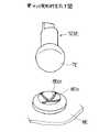
図1は、本発明のポインティングデバイスの実施例として、本体を分割した図面を示す。
【0034】
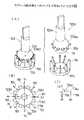
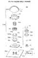
本発明のポインティングデバイスは、図1に示すように、円盤タイプのキートップ1aとスティック5とホルダ7からなる操作部15と、スライダ4と圧縮コイルスプリング3aからなる加圧部16と、マグネット(永久磁石)6と磁電変換素子9からなる座標検出部17とを、カバー2とハウジング8にて収納することにより構成され、これらの構成部品をPCB(プリント基板)10上で組み立てることにより、例えば、図2に示す様なポインティングデバイスを形成する。尚、図1に示すポインティングデバイスは、円盤タイプのキートップ1a(図8(a)参照)を使用しているが、キートップの形状は、これに限らず、オペレータの用途に応じて、例えば、ドームタイプのキートップ1b(図8(b)参照)、スティックタイプのキートップ1c(図8(c)参照)等を自由に選択可能である。
【0035】
上記、図1に示すポインティングデバイスは、例えば、コンピュータのディスプレイ上のカーソルまたはポインタを、任意の位置に移動することを可能とする。更に本発明のポインティングデバイスは、図1に示すように、操作部15の同心円上で、且つ複数の突起12間のハウジング8上に、操作部15の不要な回転を防止するためのボス11を配置することにより、より安定した操作性を実現する。
【0036】
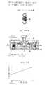
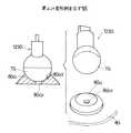
図2に示すポインティングデバイスにおいて、ホルダ7は、球状の軸受凹部としてのハウジング8に嵌合する球状の接触面を有し、手動で支持軸としてのキートップ1a及びスティック5を任意の方向に傾けることにより(図3に示す傾斜状態を参照)、球状の接触面の中心を支点(傾斜中心)として、ハウジング8上を摺動する。その際、操作部15では、支点から支持軸の垂直方向に複数個形成された突起12が、スライダ4を押し上げて圧縮コイルスプリング3aを圧縮する。
【0037】
本発明のポインティングデバイスは、加圧部16(スライダ4、圧縮コイルスプリング3a)を有することにより、操作部15(キートップ1a、スティック5、ホルダ7)を傾けた場合でも、操作部15を正立させる力(復元力)が働き、手を放すと自動的に図2に示すような正立状態に復元される。即ち、本実施例にて使用する圧縮コイルスプリング3aは、例えば、図4に示す様なスプリング形態を有し、単一のスプリングにて確実に操作部15を正立状態に復元する。
【0038】
尚、本発明の実施例にて、図5(a)に示すような引張りコイルスプリング3bを使用した場合、本発明のポインティングデバイスは、図5(b)に示すような構成となり、上記と同様に、操作部15(キートップ1a、スティック5、ホルダ7)を傾けた場合、球状の接触面の中心を支点(傾斜中心)として、ハウジング8上を摺動する。その際、操作部15では、支点から支持軸の垂直方向に複数個形成された突起12が、スライダ4を押し上げて引張りコイルスプリング3bを引っ張る。この場合、引張りコイルスプリング3bは、図5(c)に示すように、操作部15の傾斜角とスプリングの力(操作力)が比例し、傾斜角が大きく成るほどに操作力も大きくなる。
【0039】
このように、引張りコイルスプリング3bを使用した場合、本発明のポインティングデバイスは、操作部15を傾けた場合でも、作部15を正立させる力(復元力)が働き、手を放すと自動的に図5(b)に示すような正立状態に復元される。即ち、本実施例にて使用する引張りコイルスプリング3bは、例えば、図5(a)に示す様なスプリング形態を有し、複数のスプリングにて確実に操作部15を正立状態に復元する。
【0040】
また、本発明の実施例にて、図6(a)に示すような不等ピッチコイルスプリング3cを使用した場合、本発明のポインティングデバイスは、図2と同様の構成となり、操作部15(キートップ1a、スティック5、ホルダ7)を傾けた場合、球状の接触面の中心を支点(傾斜中心)として、ハウジング8上を摺動する。その際、操作部15では、支点から支持軸の垂直方向に複数個形成された突起12が、スライダ4を押し上げて不等ピッチコイルスプリング3cを圧縮する。この場合、不等ピッチコイルスプリング3cは、図6(b)に示すように、操作力の強弱により、細かな操作(微調整)と粗い操作(粗調整)が可能となる。
【0041】
このように、不等ピッチコイルスプリング3cを使用した場合、本発明のポインティングデバイスは、操作部15を傾けた場合でも、操作部15を正立させる力(復元力)が働き、手を放すと自動的に図2に示すような正立状態に復元される。即ち、本実施例にて使用する不等ピッチコイルスプリング3cは、例えば、図6(a)に示す様なスプリング形態を有し、単一のスプリングにて確実に操作部15を正立状態に復元する。
【0042】
上記、図4、図5、図6のいずれか1つのスプリングを使用する本発明のポインティングデバイスにおいて、座標検出部17は、操作部15を傾けたときのマグネット6からの磁界の変化を磁電変換素子9にて電気信号に変換し、該電気信号を信号処理することにより操作部15の傾斜方向及び傾斜角度を検出する。その結果、コンピュータのディスプレイ上のカーソルまたはポインタを任意の位置(上下左右、斜め等)に移動することが可能となる。
【0043】
ここで、本発明のポインティングデバイスを利用して、コンピュータのディスプレイ上のカーソルまたはポインタを任意の位置(上下左右、斜め等)に移動するための動作を簡単に説明する。
例えば、操作部15上の突起12を4方向に等間隔に配置する場合、操作部15を突起12の方向に傾斜させると、スライダ4の移動量が大きくなり、操作部15を隣り合う突起と突起の間の方向に傾斜させると、スライダ4の移動量が小さくなる。即ち、スライダ4の移動量が小さい突起と突起の間の方向への傾斜は、軽い操作力で操作可能となり、逆にスライダ4の移動量が大きい突起12の方向への傾斜は、前者より強い操作力が必要となる。
【0044】
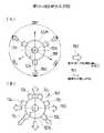
従って、図7の操作方向と突起の位置関係に示すように、軽い操作力で操作可能な突起と突起の間の4方向を、例えば、それぞれ上下左右のカーソル移動方向として定義することにより、手に与えられる操作の感覚(強弱の感覚)でカーソル移動方向を認識し易くなり、優れた操作性を実現できる。尚、操作部15上の突起12が8方向に等間隔に配置されている場合は、更に細かく、カーソル移動方向を定義することにより(上下左右、斜め等)、更に優れた操作性を実現できる。また、本発明のポインティングデバイスにて使用する突起12は、4方向及び8方向に限らず、オペレータが使用し易い数を自由に設定可能とする。
【0045】
図9は、本発明のポインティングデバイスの具体的な使用例を示す。
ここでは、ポインティングデバイスをコードレスタイプのリモコン21に応用して、コンピュータのディスプレイ上のカーソルまたはポインタを任意の位置(上下左右、斜め等)に移動させている。尚、図9では、コードレスタイプのリモコン21を一例としているが、形状はこれに限らず、コード付きのタイプでも良いし、更にコンピュータに内蔵されるようなタイプでもかまわない。
【0046】
〔第2実施例〕
図10及び図11(A),(B)は本発明の第2実施例になるポインティングデバイス120Aを示す。各図1及び図2に示す構成部分と対応する部分には、図1及び図2に示す構成部分の符号と対応する符号に添字「A」を付した符号を付す。X軸、Y軸はプリント基板10Aの上面(水平面)上の直交する軸であり、Z軸はX軸とY軸との交点OAを通る垂直軸である。Z1は上方向、Z2は下方向である。
【0047】
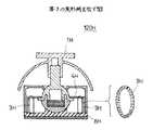
図10及び図11(A)に示すように、ポインティングデバイス120Aは、ポインティングデバイス本体組立体121Aと、4つの磁電変換素子9AX1,9AX2、9AY1,9AY2が実装してあるプリント基板10Aと、磁電変換素子9AX1〜9AY29Aからの信号を処理して所定の信号を出力する信号処理回路122Aとを有する。
【0048】
ポインティングデバイス本体組立体121Aは以下に説明するようにプリント基板10Aとは独立して組立てられたものである。ポインティングデバイス本体組立体121Aは、磁電変換素子9AX1〜9AY2を覆うようにして、プリント基板10A上に取付けられ、ドーム形状のキートップ1Aが箱状のケース122Aより上方に突き出している。
【0049】
先ず、ポインティングデバイス本体組立体121Aについて説明する。
ポインティングデバイス本体組立体121Aは、操作部15Aと加圧部16Aとが、上下に組み合わされたカバー2Aとハウジング8Aとの内部に収容された構成である。
このポインティングデバイス本体組立体121は、スティック組立体123Aをハウジング8Aの上面に支持し、スライダ4Aをスティック組立体123Aと嵌合させ、スライダ4Aに単一の圧縮コイルスプリング3Aaを搭載し、圧縮コイルスプリング3Aaを覆うようにカバー2Aを被せ、ねじ125Aによってカバー2Aとハウジング8Aとをねじ止めし、キートップ1Aをカバー2Aより上方に突き出ているスティック部124Aaに固定することによって組み立てられたものである。
【0050】
操作部15Aは、スティック組立体123Aとこの上端に固定してあるキートップ1Aとよりなる。
スティック組立体123Aは、図10に示すように、スティック124Aと、円板状であって厚さ方向に着磁してあるマグネット6Aと、半球形状のホルダ7Aとよりなる。マグネット6Aは、ホルダ7Aの内部に組み込まれており、その中心をスティック組立体123Aの軸線(Z軸)と一致させて、水平に組み込まれている。スティック124Aは、スティック部124Aaと、スティック部124Aaの下端の半球形状部124Abとよりなる。この半球形状部124Abの下端の周囲には8つの突起12AがZ軸に垂直に放射状に等角度間隔で形成してある。ホルダ7Aがスティック124Aの下端に固定してあり、ホルダ7Aと半球形状部124Abとによって球状部123Aaが形成されている。OA1はこの球状部123Aaの中心である。即ち、スティック組立体123Aは、下端に球状部123Aaを有する構成である。上記8つの突起12Aは中心OA1の位置でZ軸に垂直な面に位置している。なお、ホルダ7Aの形状は、半球形に近い多面体の形状でもよい。また、球状部123Aaは球形に近い多面体の形状でもよい。
【0051】
キートップ1Aは、キートップ本体1Aaの下側に半球形状のドーム部1Abを有する構成である。キートップ本体1Aaは、操作者の指先に対応した大きさの円板であり、この上面の中央に指先が滑らないように小さい突起1Aa1が形成してある。ドーム部1Abは、カバー2Aの円筒部2Aaを覆う大きさである。キートップ本体1Aaの下端には、角穴の嵌合凹部1Acが、ドーム部1Abの内側に突き出して形成してある。キートップ1Aは、嵌合凹部1Acを、カバー2Aの円筒部2Aaから上方に突き出ているスティック部124Aaの上端の角柱部124Aa1に嵌合させてスティック124Aの上端に固定してある。
【0052】
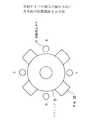
図12(A)に併せて示すように、ハウジング8Aは、その上面に、凹球状の受け座部8Aa及び8つのボス11Aが形成してある。OA2は、受け座部8Aaの球面の中心である。8つのボス11Aは板片状であり、周方向に等角度間隔で並んでおり、受け座部8Aaの周囲を囲んでいる。ハウジング8Aはエラストマー製であり、ボス11Aの先端は受け座部8Aaの周方向に容易に弾性的に撓むことが可能である。
【0053】
スティック組立体123Aは、ホルダ7Aの表面にグリースが適宜塗布された状態で、球状部123Aaのうち下側の部分を構成するホルダ7Aが凹球状の受け座部8Aaに載って支持されている。球状部123Aaのうち上半分の部分を構成する半球形状部124Abの表面には、カバー2Aのリム部2Acが当接又は僅かの隙間をおいて対向している。リム部2Acは後述するフランジ部2Abより更に中心側の部分である。よって、スティック組立体123Aは、下端の球状部123Aaを受け座部8Aaとリム部2Acによって、傾斜するように回動は可能であるけれどもX,Y,Z方向には動かないように支持されている。受け座部8Aaとリム部2Acとが球状部123Aaに対する軸受け部126を構成する。球状部123Aaは軸受け部126Aの内部で回動可能である。この状態で、図11(A)に示すように、球状部123Aaの中心OA1が受け座部8Aaの球面の中心OA2と一致している。図12(B)に併せて示すように、各突起12Aは、隣合うボス11Aの間の部分に位置している。スティック組立体123Aが正立した状態で、図12(C)に示すように、突起12Aとボス11Aとは、突起12Aの上面12Aaがボス11Aの先端面11Aaより若干上方に位置する関係にある。スティック組立体123AがZ1方向に引っ張られたとき、カバー2Aのリム部2Acの縁が半球形状部124Abの表面を受け止めて、スティック組立体123Aがカバー2Aから抜けて外れることが制限される。
【0054】
加圧部16Aは、スライダ4Aと圧縮コイルスプリング3Aaとよりなる。
スライダ4Aは、図11(A)及び図13に示すように、略円筒形状を有し、周囲寄りの部分に環状の凹部である圧縮コイルスプリング収容部4Aaを有し、上面の中心側に環状のフランジ部4Abを有し、外周面に複数のリブ4Acが形成してある。各リブ4Acはスライダ4Aの軸線4AZの方向に延在している。
【0055】
圧縮コイルスプリング3Aaは、下寄りの部分をスライダ4Aの圧縮コイルスプリング収容部4Aaに嵌合させてスライダ4Aに取り付けてあり、上寄りの部分がスライダ4Aより上方に突き出ている。圧縮コイルスプリング3Aaに代えて、図6(a)に示す、不等ピッチコイルスプリング3cを使用してもよい。
スライダ4Aは、図11(A)に示すように、スティック組立体123Aの 半球形状部124Abに嵌合し、周方向に並んでいる8つのボス11Aの外側に嵌合しており、環状のフランジ部4Abが8つの放射状の突起12Aの上面に当接している。
【0056】
スライダ4Aは、カバー2Aの円筒部2Aa内にZ1,Z2方向に摺動可能に嵌合してある。カバー2Aは円筒部2Aaの上端より中心側に張り出た環状のフランジ部2Abを有する。圧縮コイルスプリング3Aaの上端は、カバー2Aの環状フランジ部2Abの裏面に当たっている。圧縮コイルスプリング3Aaは少し圧縮された状態にある。スライダ4Aは、ハウジング8Aの上面より若干浮いている。
【0057】
ハウジング8Aの裏面には、磁電変換素子9AX1,9AX2、9AY1,9AY2が嵌合するための凹部8Abが形成してある。
以上が、ポインティングデバイス本体組立体121の構成である。
プリント基板10A上には、2つの磁電変換素子9AX1,9AX2がX軸上に並んで、2つの磁電変換素子9AY1,9AY2がY軸上に並んで、且つ点OAを中心に対称に配置されている。
【0058】
このポインティングデバイス本体組立体121Aが、図11(A)に示すように、凹部8Abが磁電変換素子9AX1,9AX2,9AY1,9AY2と嵌合して覆うようにして、PCB(プリント基板)10A上に取付けられ、更に箱状のケース122Aがポインティングデバイス本体組立体121Aを覆うように取付けられて、ポインティングデバイス120Aが完成する。
【0059】
ポインティングデバイス120Aの箱状のケース122Aの開口122Aaがドーム部1Abと嵌合しており、キートップ本体1Aaがケース122Aより上方に突き出ている。ケース122Aの開口122Aaの周囲のリム部122Abは、ドーム部1Abのうち周囲寄りの部分を覆っている。
上記のポインティングデバイス本体組立体121Aはプリント基板10Aとは独立して組み立てられる。ポインティングデバイス120Aは独立して組み立てられたポインティングデバイス本体組立体121Aをプリント基板10A上に実装することによって完成する。よって、プリント基板10A上にスティック組立体123A、スライダ4A等の部品を組み付けてポインティングデバイスを製造する場合に比べて、ポインティングデバイス120Aは効率良く製造される。
【0060】
ポインティングデバイス120Aが完成した状態で(キートップ本体1Aaを操作しない状態で)、圧縮コイルスプリング3Aaのばね力がスライダ4Aを下方向に押しており、環状フランジ部2Abが8つの放射状の突起12Aを均一に下方向に押しており、スティック組立体123Aは垂直の姿勢にあり、キートップ1Aは真上に位置しており、操作部15Aは正立状態にある。
【0061】
スティック組立体123A内のマグネット6Aはプリント基板10A上の点OAの真上に位置しており、全部の磁電変換素子9AX1,9AX2,9AY1,9AY2には同じ強さの磁界が作用しており、後述するように信号処理回路122Aからの出力値は128カウントである。
スティック組立体123Aは、図11(B)に示すように、スライダ4Aが圧縮コイルスプリング3Aaを圧縮させつつ上方に変位する動作を伴って、360度の任意の方向に傾斜することが可能である。スティック組立体123Aは、球状部123Aaが軸受け部126Aの内側で点OA1(OA2)を中心に回動しつつ、且つ半球状のホルダ7Aが凹球状の受け座部8Aaを滑りつつ、点OA1(OA2)を中心に回動するように傾斜する。スティック組立体123Aは、最大では、突起12Aがカバー2Aのリム部2Acに当たる角度まで傾斜する。
【0062】
ここで、スティック組立体123Aを傾斜させたときの回動中心がスティック組立体123Aの下端面ではなくて、下端面より寸法h上方の位置であるため、スティック組立体123Aが所定の最大の角度傾斜するためにキートップ本体1Aaが移動する範囲(操作領域)は、スティック組立体が受け座部と接触している下端を中心として傾斜する構成に比べて狭くなり、よって、ポインティングデバイス120Aは小型である。
【0063】
ポインティングデバイス120Aは、図11(B)に示すように、操作者が指先150をキートップ本体1Aaに当ててキートップ1Aを所望の方向に倒すように任意の方向に移動させて操作される。スティック組立体123Aは、球状部123Aaが軸受け部126の内側で点OA1(OA2)を中心に回動しつつ、8つの放射状の突起12Aのうちの一つ又は二つが環状フランジ部2Abを押し上げ、スライダ4Aを圧縮コイルスプリング3Aaを圧縮させつつ上方に変位させる動作を伴って、任意の方向に傾斜させられる。圧縮コイルスプリング3Aaばね力によって、半球状のホルダ7Aが凹球状の受け座部8Aaに押し付けられつつ摺動する。半球状のホルダ7Aにはグリースが塗ってあり、半球状のホルダ7Aが凹球状の受け座部8Aa上を円滑に摺動する。
【0064】
マグネット6Aは点OAより少し下側に位置している。よって、図11(B)に示すように、マグネット6Aは点OAを中心とする円弧に沿って変位し、各磁電変換素子9Aに作用する磁界の強さのバランスがくずれて、後述するように信号処理回路122Aから、キートップ本体1Aaの操作方向(傾斜方向)及び傾斜角度に対応する信号が出力される。
【0065】
操作者が指先150をキートップ本体1Aaから離すと、圧縮コイルスプリング3Aaのばね力でもって、スライダ4Aが下方向に押し下げられ、環状フランジ部2Abが上方に変位した突起12Aを押し下げて8つの放射状の突起12Aを均一に下方向に押した状態となり、スティック組立体123A及びキートップ1Aは図11(A)に示す正立状態に復元される。
【0066】
ポインティングデバイス120Aは操作の方向によって抵抗力が若干相違する。図12(B)中、X1方向はこれと反対の方向が突起が位置していず、隣合う突起12A1、12A2の中間である方向である。B方向はこれと反対の方向に突起12A1が位置する方向である。
スティック組立体123AをB方向に傾斜させるように操作した場合にスライダ4Aを押し上げるものは突起12A1である。スティック組立体123AをX1方向に傾斜させるように操作した場合にスライダ4Aを押し上げるものは突起12A1と突起12A2である。スティック組立体123Aを同じ角度A方向に傾斜させたときの突起12A1の先端の高さと、X1方向に傾斜させたときの突起12A1(12A2)の先端の高さとを比較すると、前者の方が後者より若干高い位置に位置する。よって、スティック組立体123AをB方向に傾斜させるように操作する場合には操作が、スティック組立体123AをX1方向に傾斜させるように操作する場合に比べて若干重く感じられる。この操作力の違いによって、ポインティングデバイス120Aの操作の方向を認識することが可能である。
【0067】
図12(B)中、矢印151で示す方向が操作力が軽くて操作し易い方向である。
次に、上記ポインティングデバイス120A及びポインティングデバイス本体組立体121の特長について説明する。
ポインティングデバイス120A及びポインティングデバイス本体組立体121Aは以下の特長を有する。
【0068】
▲1▼操作力の低減化
図13に示すように、スライダ4Aとカバー2Aの円筒部2Aaとは、スライダ4Aの周面の複数のリブ4Acが円筒部2Aaの内周面と接触した状態にあり、スライダ4Aとカバー2Aの円筒部2Aaとの接触は面接触ではなく、線接触である。このため、面接触である場合に比べて、スライダ4Aがカバー2Aの円筒部2Aaの内部を上方に摺動するときの摩擦が小さくなる。これによって、キートップ本体1Aaの操作が軽くなり、操作性が向上する。
【0069】
▲2▼キートップ本体1Aaの抜け防止
図11に示すように、ケース122Aのリム122Abが、ドーム部1Abのうち周囲寄りの部分を覆っているため、キートップ本体1Aaを上方に強く引っ張った場合にも、ケース122Aが邪魔をしてキートップ1Aがスティック124Aから抜けてしまうことが防止される。
【0070】
▲3▼キートップ本体1Aaの回り止め
図10、図11及び図12に示すように、キートップ1Aとスティック124Aとは角穴の嵌合凹部1Acと角柱部124Aa1とが嵌合しており、キートップ1Aはスティック124Aに対して回らないようになっている。また、スティック組立体123Aの放射状の突起12Aが隣合うボス11Aの間に位置しており、スティック組立体123Aはハウジング8Aに対して回らないようになっている。よって、悪戯でキートップ1AをZ軸を中心に回動させようとしても、突起12Aがボス11Aに当たって、キートップ1Aは回動しないようになっている。この構成は、キートップ本体1Aaの上面に向きを示す印があってキートップ本体1Aaに方向性がある場合に適用して効果がある。
【0071】
▲4▼無理にキートップ本体1Aaの回しても壊れない。
キートップ本体1Aaにこれを回そうとする強い力を加えた場合には、突起12Aがボス11Aの上端付近を押す。ボス11Aはエラストマー製であるため、折れることなく、図12(C)に二点鎖線で示すように撓んで、その後に復元する。よって、突起12Aがボス11Aを乗り越えてキートップ本体1Aaが少し回動されることになるけれども、ボス11Aが折れて、キートップ本体1Aaが壊れることは起きない。
【0072】
▲5▼ゴミの侵入防止
図11に示すように、ケース122Aの開口122Aaがドーム部1Abによって塞がれている。よって、ゴミがケース122Aの内部に侵入することが防止される。
次に、信号処理回路122Aについて説明する。
【0073】
図14に示すように、信号処理回路122Aは、二つの増幅器130、131、A/D変換器132、及び中央演算処理装置(CPU)133とを有する。中央演算処理装置133は、演算部140、記憶部141、クロック部142、及びインタフェース部143よりなる。
X軸上に並んで配置された二個の磁電変換素子9AX1,9AX2の出力電圧は増幅器130で差動増幅される。Y軸上に並んで配置された二個の磁電変換素子9AY1,9AY2の出力電圧は増幅器131で差動増幅される。増幅された電圧はA/D変換器132でA/D変換され、中央演算処理装置133に加えられる。中央演算処理装置133では、A/D変換されたデータが、クロックに同期して記憶部141のデータと比較演算され、インタフェース部143でコンピュータが認識できるように変換されてコンピュータに出力される。
【0074】
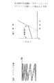
図15は、キートップ本体1Aaを例えばX−Z面内で傾斜させた場合の傾斜角と増幅器130で差動増幅された電圧との関係を示す。傾斜角が零であるときには、電圧はb(V)である。線Iで示すように、傾斜角に対して電圧はリニアに変化し、傾斜角が−30度のときにa(V)の電圧が出力され、傾斜角が+30度のときにc(V)の電圧が出力される。
【0075】
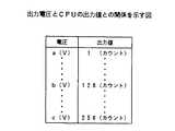
図16は中央演算処理装置133からの出力を示す。例えば、a(V)のときに1カウント、b(V)のときに128カウント、c(V)のときに256カウントが出力される。
図17は中央演算処理装置133の出力と表示画面上のカーソルの移動速度との関係を示す。線IIで示すように、例えば、1カウントのときはカーソルは速度Aで移動し、128カウントのときはカーソルは動かない。256カウントのときはカーソルは1カウントのときと逆方向に速度Aで移動する。
【0076】
なお、キートップ本体1Aaの傾斜方向は、中央演算処理装置133において、増幅器130の出力電圧と増幅器131の出力電圧との割合に基づいて判断される。
これによって、キートップ本体1Aaを操作することによって、表示画面上のカーソルがキートップ本体1Aaを傾斜させた方向に傾斜させた角度に対応した速度で移動される。
【0077】
〔第2実施例の各部の変形例〕
〔第1の変形例〕
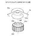
図18は第1の変形例を示す。キートップ1Bは、半球形状のドーム部1Bbの内面に、溝1Bb1を有する。カバー2Bは、円筒部2Baの周面に、縦方向のリブ2Ba1を有する。溝1Bb1及びリブ2Ba1は周方向上90度間隔で形成してある。キートップ1Bは、溝1Bb1を対応するリブ2Ba1に嵌合させて取り付けてある。
【0078】
溝1Bb1が対応するリブ2Ba1と嵌合していることによって、キートップ1Bはカバー2Bに対して四個所で回り止めされている。
〔第2の変形例〕
図19は第2の変形例を示す。スティック組立体123Cの半球形状のホルダ7Cは、十字形状のリブ7C1を有する。ハウジング8Cの受け座部8Caは、その凹球状の面に十字形状の溝8Ca1を有する。スティック組立体123Cの半球形状のホルダ7Cは、十字形状のリブ7C1が十字形状の溝8Ca1に嵌合した状態で受け座部8Caに支持されている。
【0079】
リブ7C1が溝8Ca1に嵌合していることによって、スティック組立体123C(キートップ)はハウジング8Cに対して回り止めされている。
〔第3の変形例〕
図20は第3の変形例を示す。ハウジング8Dの受け座部8Daは、その凹球状の面に環状の突条部8Da1を有する。突条部8Da1は断面が半円形状である。スティック組立体123Dの半球形状のホルダ7Dは、環状の突条部8Da1に当接した状態で、受け座部8Daに支持されている。
【0080】
スティック組立体123Dは、ホルダ7Dが環状の突条部8Da1上を摺接しつつ傾斜される。よって、ホルダ7Dの受け座部8Daに対する接触は線接触となり、面接触の場合に比べて摩擦力は少ない。これによって、キートップ本体の操作が軽くなり、ポインティングデバイスは良好な操作性を有する。
〔第4の変形例〕
図21は第4の変形例を示す。ハウジング8Eの受け座部8Eaは、その凹球状の面に、図20中の環状の突条部8Da1に代えて、上方からみて十字形状の突条部8Ea1を有する。突条部8Ea1は断面が半円形状である。
【0081】
スティック組立体123Eが傾斜されるとき、ホルダ7Eが十字形状の突条部8Ea1と線接触しつつ摺接する。これによって、キートップ本体の操作が軽くなり、ポインティングデバイスは良好な操作性を有する。
〔第5の変形例〕
図22は第5の変形例を示す。ハウジング8Fの受け座部8Faは、その凹球状の面に、図20中の環状の突条部8Da1に代えて、三つの半球状の凸部8Fa1を周方向上等間隔で配してある構成である。
【0082】
スティック組立体123Fが傾斜されるとき、ホルダ7Fが凸部8Fa1と点接触しつつ摺接する。これによって、キートップ本体の操作が軽くなり、ポインティングデバイスは良好な操作性を有する。
〔第6の変形例〕
図23は第6の変形例を示す。ゴミが受け座部受け座部8Gaとホルダ7Gとの間に入ると、ホルダ7Gが摺接しにくくなって、ポインティングデバイスは操作性が悪くなる虞れがある。
【0083】
そこで、ハウジング8Gの凹球状の面の受け座部8Gaは、その最深部に穴8Ga1が形成してある。この穴8Ga1が形成してあることによって、受け座部8Gaの凹球状の面上に侵入したゴミはスティック組立体123Fの操作によって寄せられて上記穴8Ga1内に入り込み、受け座部8Gaの凹球状の面から排除される。よって、ゴミが受け座部受け座部8Gaとホルダ7Gとの間に入った場合にも、ポインティングデバイスは良好な操作性を維持する。
【0084】
この穴8Ga1に代えて、図23に二点鎖線で示すように溝8Ga2を設けてもよい。
〔第7の変形例〕
第7の変形例及び次の第8の変形例は、圧縮コイルスプリング3Aaの変形例である。
【0085】
図24は第7の変形例を示す。ポインティングデバイス120Hは、圧縮コイルスプリング3Aaに代えて、コイルバネをリング状にしたガータスプリング3Hが、スライダ4Hとハウジング8Hとの間にかけてある構成である。このガータスプリング3Hのばね力によって、スライダ4Hが下向きに付勢されている。
〔第8の変形例〕
図25(A)は第8の変形例を示す。ポインティングデバイス120Iは、圧縮コイルスプリング3Aaに代えて、ドーム形状のラバースプリング3Iが、スライダ4Iとカバー2Iのフランジ部2Ibとの間に設けてある構成である。キートップ1Iを操作すると、ドーム形状のラバースプリング3Iが図25(B)に示すように弾性変形し、スライダ4Iを下向きに付勢する。
【0086】
〔第9の変形例〕
図26は第9の変形例を示す。キートップ1Jは、半球形状のドーム部1Jbより上方にスティック部1Jaが突き出ている構成である。
操作者は指先でスティック部1Jaを摘んで操作する。
〔第10の変形例〕
図27(A),(B)は第9の変形例を示す。図27(A)は、Z軸に垂直である放射状の突起12Kが3つ等角度間隔で形成してある構成である。図27(B)は、6つの放射状の突起12Lが不等間隔で並んでいる構成である。
【0087】
太い矢印150はスティック組立体123K、123Lを傾斜させるように操作した場合の操作力が軽い方向である。細い矢印151はスティック組立体123K、123Lを傾斜させるように操作した場合の操作力が重い方向である。
〔第3実施例〕
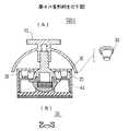
図28は本発明の第3実施例になる加速度計測装置160を示す。図29及び図30(A),(B)は加速度検出装置161を示す。
【0088】
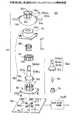
図28に示す加速度計測装置160は、プリント基板10M上に加速度検出装置161、CPU133、LED162−1〜162−3、赤外線通信ユニット163、加速度計測開始スイッチ164、計測データ転送開始スイッチ165が搭載してあり、且つ、各スイッチ164、165上にキートップ166、167が載っており、これらが、ねじ止めされた下カバー168と上カバー169との間に収容され、ボタン電池170がプリント基板10Mの裏面側に収まっており蓋171で覆われている構成である。この加速度計測装置160は、ベルト172に取り付けてあり、図33に示すようにゲームのプレーヤ180が手首181及び足首182に装着して使用される。
【0089】
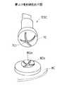
加速度検出装置161は、図10のポインティングデバイス本体組立体121Aにおいて、キートップ1Aの代わりに、スティック組立体123Mの上端のカップ部123Mb内に円板形状の重り173が取り付けてあり、且つ、重り173を覆うようにドーム形状のカバー174が固定してある構成である。カバー174は、上カバー169のドーム形状の透明の窓169aに対向している。
【0090】
スティック組立体123Mは、図10中の突起12Aに代えて、環状のフランジ12Mが形成してある。環状のフランジ12Mの上面は、スライダ4Aの環状のフランジ部4Abを受けている。スティック組立体123Mが傾斜するときに、環状のフランジ部4Abがスライダ4Aの環状のフランジ部4Abを押し上げる。よって、スティック組立体123Mがどの方向に傾斜する場合にもスティック組立体123Mが受ける抵抗力は同じであり、加速度検出装置161は方向性を有していず、X−Y面上どの方向の加速度も精度良く計測することが出来る。
【0091】
ハウジング8Mは、ボス11Aを有していない。このためスティック組立体123Mはその軸線(Z)に関して回動してしまうことが起きる。しかし、厚さ方向に着磁してあるは円板状であってスティック組立体123Mの軸線(Z)上に配置してあるため、スティック組立体123Mがその軸線(Z)に関して回動したとしても加速度検出には影響は及ばず、不都合はない。
【0092】
上記以外は図10のポインティングデバイス本体組立体121Aと同じ構成である。図29及び図30(A),(B)中、図10に示す構成部分と対応する部分には、図10と同じ符号を付し、その説明は省略する。
スティック組立体123Mは、スライダ4Aが圧縮コイルスプリング3Aaを圧縮させつつ上方に変位する動作を伴って、360度の任意の方向(X−Y平面である二次元上任意の方向)に傾斜することが可能である。よって、重り173に加速度が作用した場合に、スティック組立体123Mは、図30(B)に示すように、加速度の方向に、加速度の大きさに対応した角度傾斜される。図31の線III で示すように、スティック組立体123Mの傾斜角は重り173に作用する加速度の大きさに対してリニアに変化する。スライダ4Aの環状のフランジ部4Abに当たっているのは環状のフランジ12Mであるため、X−Y平面である二次元上どの方向についても、スティック組立体123Mの傾斜角は重り173に作用する加速度の大きさに対して同じようにリニアに変化する。重り173に作用する加速度が減って零になると、スティック組立体123Mは、圧縮コイルスプリング3Aaのばね力によって図30(A)の正立状態に復元する。
【0093】
信号処理回路122Mは図14の構成と同じである。CPU133は加速度を検出するような処理動作を行なう。
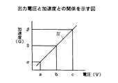
加速度計測装置160に加速度が作用した場合に、図31に示すように、スティック組立体123Mの傾斜角の傾斜角は重り173に作用する加速度の大きさに対してリニアに変化する。ここで、図15に示すように、スティック組立体123Mの傾斜角と出力電圧は比例している。よって、図32に線IVで示すように、電圧aのときに加速度がα、電圧bのとき加速度が零、電圧cのときに加速度がβと検出される。
【0094】
図33に示すようにゲームのプレーヤ180が加速度計測装置160を装着して手足を振ったときには、加速度計測装置160の信号処理回路122Mの増幅器130、131(図14参照)からは、図34に線V で示す電圧波形が出力される。中央演算処理装置133が、加速度の大きさと時間とに基づいて、プレーヤ180が手足を動かした速さ(ゆっくり動かしたか、素早く動かしたか)を測定する。時間の測定はクロック部142のクロックと同期をとることによってなされる。
【0095】
図33に示すように、プレーヤ180がキックボクシングのボクサになったつもりで手足を動かすジェスチャをすると、ゲーム装置の画面190上では、仮想人物191がプレーヤ180と対応した動きをして、敵192に攻撃をくわえる。
なお、加速度検出装置161は、図19乃至図25に示す変形例が適用された構成とすることも可能である。
【0096】
【発明の効果】
上述の如く、請求項1の発明は、操作部を傾斜させるように操作してコンピュータのディスプレイ上のカーソルまたはポインタを任意の位置に移動可能なポインティングデバイスにおいて、該操作部は、その下端に略球状部を有し、且つ、前記略球状部より外側に突き出た複数の突起を有する構成であり、該操作部の上記略球状部を回動するように支持する軸受け手段と、前記複数の突起間に配置されて、前記操作部の回転を防止するボスと、
前記突起に作用して、上記略球状部が該軸受け手段の内部で回動して傾斜された操作部を正立位置に復元させる復元手段と、該操作部の傾斜方向及び傾斜角度を検出する傾斜検出手段とよりなる構成としたものであるため、複数の突起とボスは、悪戯で操作部を回動させようとしても、操作部が回動しないように出来る。よって、操作部の上面に向きを示す印があって操作部に方向性がある場合に適用して効果がある。また、安定した操作性が実現できる。
請求項2の発明は、操作部を傾斜させるように操作してコンピュータのディスプレイ上のカーソルまたはポインタを任意の位置に移動可能なポインティングデバイスにおいて、該操作部は、その下端に略球状部を有し、且つ、前記略球状部より外側に突き出て複数の方向に不等間隔に配置された複数の突起を有する構成であり、該操作部の上記略球状部を回動するように支持する軸受け手段と、前記突起に作用して、上記略球状部が該軸受け手段の内部で回動して傾斜された操作部を正立位置に復元させる復元手段と、該操作部の傾斜方向及び傾斜角度を検出する傾斜検出手段とよりなる構成としたものであり、複数の突起とボスは、悪戯で操作部を回動させようとしても、操作部が回動しないようにするので、操作部の上面に向きを示す印があって操作部に方向性がある場合に適用して効果があり、また、安定した操作性が実現できる。複数の突起が複数の方向に不等間隔に配置してあるので、操作部を傾斜させた方向を認識出来るようになって優れた操作性を有するように出来る。
請求項3の発明は、操作部を傾斜させるように操作してコンピュータのディスプレイ上のカーソルまたはポインタを任意の位置に移動可能なポインティングデバイスにおいて、該操作部はその下端に略球状部を有し、且つ、前記略球状部より外側に突き出た複数の突起を有する構成であり、該操作部の上記略球状部を回動するように支持する軸受け手段と、前記突起に作用して、上記略球状部が該軸受け手段の内部で回動して傾斜された操作部を正立位置に復元させる復元手段と、該操作部の傾斜方向及び傾斜角度を検出する傾斜検出手段とよりなり、上記復元手段は、円筒部を有するカバーと、該カバーの該円筒部内に摺動可能に設けてあり、下端が上記突起に支持されているスライダと、該スライダを下方にばね付勢するばねとよりなり、前記操作部が傾斜されると該スライダが該突起によって押し上げられ、該ばねが弾性変形し、前記操作部の操作が解除されると、該ばねの弾性力によって該スライダが押し下げられて、該スライダが上記突起を押して、該操作部が復元される構成であり、上記スライダは、周面に複数のリブを有し、該リブが該円筒部の内周面と線接触をする構成としたものであり、略球状部より外側に突き出た複数の突起に支持されているスライダが、周面に複数のリブを有し、このリブが円筒部の内周面と線接触をする構成であるため、スライダの周面と円筒部の内周面とが面接触する場合に比べて、スライダが円筒部を上方に摺動する場合の摩擦力を小さくすることが出来、よって、操作が軽いポインティングデバイスを実現することが出来る。
請求項4の発明は、操作部を傾斜させるように操作してコンピュータのディスプレイ上のカーソルまたはポインタを任意の位置に移動可能なポインティングデバイスにおいて、該操作部は、その下端に略球状部を有し、且つ、前記略球状部より外側に突き出た複数の突起を有する構成であり、該操作部の上記略球状部を回動するように支持する軸受け手段と、前記突起に作用して、上記略球状部が該軸受け手段の内部で回動して傾斜された操作部を正立位置に復元させる復元手段と、該操作部の傾斜方向及び傾斜角度を検出する傾斜検出手段とよりなり、前記操作部は、ドーム部を更に有し、上記復元手段は、該ドーム部によって覆われる円筒部を有するカバーを有し、該ドーム部は、内周面に径方向に延在する溝を有し、該円筒部は、周面側に上記溝に対応したリブを有し、該ドーム部の溝が上記円筒部のリブに嵌合している構成としたものであり、ドーム部がカバーに対して回り止めされ、悪戯で操作部を回動させようとしても、操作部は回動しないようになり、よって、操作部の上面に向きを示す印があって操作部に方向性がある場合に適用して効果がある。
請求項5の発明は、センサを備えた基板に取付けられる入力装置本体であって、下端に略球状部を有し、且つ、前記略球状部より外側に突き出た複数の突起を有し、傾斜させるように操作される操作部と、該操作部の上記略球状部を回動するように支持する軸受け手段と、前記複数の突起間に配置されて、前記操作部の回転を防止するボスと、前記突起に作用して、上記略球状部が該軸受け手段の内部で回動して傾斜された操作部を正立位置に復元させる復元手段と、前記略球状部に設けてある被検出体とよりなり、上記基板に取付けられて、上記センサによって上記被検出体の傾斜方向及び傾斜角度が検出される構成としたものであり、入力装置本体が移動部と軸受け手段と復元手段と被検出体とよりなり、センサを備えた基板に取付けられる構成であるため、入力装置本体をセンサを備えた基板とは独立して組み立てることが出来、独立して組み立てた入力装置本体をセンサを備えた基板に取付けることによって入力装置を製造すすることが出来、よって、センサを備えた基板上に軸受け手段、移動部、復元手段を順次組み付ける場合に比べて、入力装置を効率良く製造することが出来る。
【図面の簡単な説明】
【図1】本発明の第1実施例である。
【図2】本発明の実施例の正立状態を示す図である。
【図3】本発明の実施例の傾斜状態を示す図である。
【図4】本発明の実施例にて使用する圧縮コイルスプリングを示す図である。
【図5】本発明の実施例にて引張りコイルスプリングを使用した場合を示す図である。
【図6】本発明の実施例にて不等ピッチコイルスプリングを使用した場合を示す図である。
【図7】突起が4つの場合の操作方向と各突起の位置関係を示す図である。
【図8】各種キートップを示す図である。
【図9】本発明のポインティングデバイスの具体例である。
【図10】本発明の第2実施例のポインティングデバイスの分解斜視図である。
【図11】本発明の第2実施例のポインティングデバイスを示す図である。
【図12】スティック組立体とハウジングとを対応させて示す図である。
【図13】スライダとホルダとを対応させて示す図である。
【図14】図10中の信号処理回路のブロック図である。
【図15】キートップ本体の操作と出力電圧との関係を示す図である。
【図16】出力電圧とCPUの出力値との関係を示す図である。
【図17】CPUの出力値とカーソルの移動速度との関係を示す図である。
【図18】第1の変形例を示す図である。
【図19】第2の変形例を示す図である。
【図20】第3の変形例を示す図である。
【図21】第4の変形例を示す図である。
【図22】第5の変形例を示す図である。
【図23】第6の変形例を示す図である。
【図24】第7の変形例を示す図である。
【図25】第8の変形例を示す図である。
【図26】第9の変形例を示す図である。
【図27】第10の変形例を示す図である。
【図28】本発明の第2実施例の加速度計測装置を示す分解斜視図である。
【図29】図28中の加速度検出装置の分解斜視図である。
【図30】加速度検出装置を示す図である。
【図31】加速度とスティック組立体との関係を示す図である。
【図32】出力電圧と加速度との関係を示す図である。
【図33】加速度計測装置の使用例を示す図である。
【図34】プレーヤが手足を振ったときの出力電圧の波形を示す図である。
【図35】従来のポインティングデバイスを示す図である。
【符号の説明】
1a キートップ(円盤タイプ)
1b キートップ(ドームタイプ)
1c キートップ(スティックタイプ)
2 カバー
3a 圧縮コイルスプリング
3b 引張りコイルスプリング
3c 不等ピッチコイルスプリング
4 スライダ
5 スティック
6 マグネット(永久磁石)
7 ホルダ
8 ハウジング
9 磁電変換素子
10 PCB(プリント基板)
11 ボス
12 突起
15 操作部
16 加圧部
17 座標検出部
21 リモコン
101 操作桿
102 支持フレーム
103 密巻コイルばね
104 座標検出部
105 発光素子
106 受光素子
107 プリント基板
120A ポインティングデバイス
121A ポインティングデバイス本体組立体
122A,122M 信号処理回路
123A,123M スティック組立体
123Aa 球状部
126A 軸受け部
160 加速度計測装置
161 加速度検出装置
172 ベルト
173 重り[0001]
BACKGROUND OF THE INVENTION
The present invention relates to an input device for inputting information to a computer or the like, and more particularly to a pointing device for moving a pointer or cursor to an arbitrary position on a computer display and an acceleration measuring device for measuring acceleration.
[0002]
In recent years, for example, a pointing device is often used as a data input unit with excellent operability in addition to a keyboard in a computer or the like.
In addition, for example, a mouse or a digitizer is used as a pointing device for a desktop type computer, but it is often used in places where there is no table such as outdoors or in a car. With the advent of computer-type computers, pointing devices are also diversifying as data input means to replace the mouse, which is difficult to secure the operation area.
[0003]
Therefore, pointing devices having various shapes such as a trackball type that can be miniaturized for a portable computer and do not require an operation area have been developed.
[0004]
[Prior art]
FIG. 35 is a diagram illustrating an example of a conventional pointing device.
As shown in FIG. 35, the conventional pointing device has an
[0005]
For example, a
The light
[0006]
As a result, the light from the
[0007]
[Problems to be solved by the invention]
However, the conventional pointing device is difficult to handle because of its large outer shape and weight. That is, there is a problem that the operability is poor for an infant without power.
The present invention can be operated regardless of age, and is further compact and has good operability.pointing deviceI will provide a.
[0008]
[Means for Solving the Problems]
In order to solve the above-described problem, a pointing device according to the present invention is a pointing device capable of moving a cursor or a pointer on a computer display to an arbitrary position as described in
[0009]
As shown in FIG. 35, the conventional pointing device is difficult to handle because it has a large external shape and a large weight. That is, there is a problem that the operability is poor for an infant who has no power and a small hand. In addition, when the tightly wound
[0010]
Therefore, the pointing device of the present invention uses the center of the spherical contact surface as a fulcrum, the operation part forms a plurality of protrusions in the direction perpendicular to the support shaft from the fulcrum, and the protrusion pushes up the slider when the operation part is inclined. By configuring the coil spring to expand and contract, a small pointing device is realized.
In addition, since the pointing device is downsized and the slider is held vertically by the spring, a light operable coil spring can be used, and the operability can be improved. Furthermore, the slider and the tilted operation portion can be reliably restored to the original positions by the restoring force of the coil spring.
[0011]
In addition, a boss (corresponding to the
Since the above pointing device can prevent unnecessary rotation of the operation unit, stable operability can be realized.
Further, the projections on the operation unit (corresponding to the
[0012]
For example, when the projections on the operation unit are arranged at equal intervals in four directions, if the operation unit is tilted in the direction of the projection, the amount of movement of the slider increases, and the operation unit is positioned between adjacent projections. When it is inclined in the direction, the amount of movement of the slider becomes smaller. That is, the inclination in the direction between the protrusions with a small amount of movement of the slider can be operated with a light operating force. On the contrary, the inclination in the direction of the protrusion with the large moving amount of the slider requires a stronger operating force than the former.
[0013]
Therefore, by defining the four directions between the protrusions that can be operated with a light operating force as, for example, the up / down / left / right cursor movement directions, the cursor movement directions can be easily recognized, and excellent operability can be realized. . When the protrusions on the operation unit are arranged at equal intervals in eight directions, excellent operability can be realized by defining the cursor movement direction more finely.
[0014]
According to the first aspect of the present invention, in the pointing device capable of moving the cursor or pointer on the computer display to an arbitrary position by operating the operation unit to tilt, the operation unit has a substantially spherical portion at the lower end.And having a plurality of protrusions protruding outward from the substantially spherical portion.Bearing means for supporting the substantially spherical portion of the operation portion so as to rotate;A boss disposed between the plurality of protrusions to prevent rotation of the operation portion, and acting on the protrusion,A configuration comprising: a restoring means for restoring the operation section tilted by rotating the substantially spherical portion inside the bearing means to an upright position; and an inclination detection means for detecting an inclination direction and an inclination angle of the operation section. It is what.
The plurality of protrusions and the boss prevent the operation unit from rotating even if the operation unit is rotated by mischief. Therefore, the present invention is effective when applied to a case where there is a mark indicating the direction on the upper surface of the operation unit and the operation unit has directionality. In addition, stable operability can be realized.
According to a second aspect of the present invention, in the pointing device capable of moving the cursor or pointer on the computer display to an arbitrary position by operating the operation unit to tilt, the operation unit has a substantially spherical portion at a lower end thereof. And a bearing having a plurality of protrusions protruding outward from the substantially spherical portion and arranged at unequal intervals in a plurality of directions, and supporting the substantially spherical portion of the operation portion so as to rotate. Means, a restoring means which acts on the protrusion and causes the substantially spherical portion to rotate inside the bearing means to restore the tilted operation portion to an upright position, and an inclination direction and an inclination angle of the operation portion And an inclination detecting means for detecting
Multiple protrusions and bosses prevent the operation unit from rotating even if the operation unit is rotated by mischief, so the operation unit has a direction mark and the operation unit has directionality It is effective when applied to and can achieve stable operability. Since the plurality of protrusions are arranged at unequal intervals in a plurality of directions, it is possible to recognize the direction in which the operation unit is inclined and to have excellent operability.
According to a third aspect of the present invention, in the pointing device capable of moving the cursor or pointer on the computer display to an arbitrary position by operating the operation unit to tilt, the operation unit has a substantially spherical portion at a lower end thereof. And a plurality of protrusions protruding outward from the substantially spherical portion, the bearing means for supporting the substantially spherical portion of the operation portion so as to rotate, and acting on the protrusion, The restoring portion includes a restoring means for restoring the operation portion tilted by rotating the spherical portion inside the bearing means to an upright position, and an inclination detecting means for detecting the inclination direction and the inclination angle of the operation portion. The means includes a cover having a cylindrical portion, a slider that is slidably provided in the cylindrical portion of the cover, a lower end supported by the protrusion, and a spring that biases the slider downward. When the operation portion is inclined, the slider is pushed up by the protrusion, the spring is elastically deformed, and when the operation portion is released, the slider is pushed down by the elastic force of the spring, and the slider Is configured such that the operation portion is restored by pressing the protrusion, and the slider has a plurality of ribs on the peripheral surface, and the ribs are in line contact with the inner peripheral surface of the cylindrical portion. It is.
The slider supported by the plurality of protrusions protruding outward from the substantially spherical portion has a plurality of ribs on the peripheral surface, and this rib is in line contact with the inner peripheral surface of the cylindrical portion. Compared to the case where the peripheral surface and the inner peripheral surface of the cylindrical portion are in surface contact, it is possible to reduce the frictional force when the slider slides upward on the cylindrical portion, thereby realizing a pointing device that is light in operation. I can do it.
According to a fourth aspect of the present invention, in the pointing device capable of moving the cursor or pointer on the computer display to an arbitrary position by operating the operation unit to tilt, the operation unit has a substantially spherical portion at the lower end thereof. And a plurality of protrusions protruding outward from the substantially spherical portion, bearing means for supporting the substantially spherical portion of the operation portion so as to rotate, and acting on the protrusion, The substantially spherical portion is composed of a restoring means for restoring the operation portion inclined by rotating inside the bearing means to an upright position, and an inclination detection means for detecting the inclination direction and the inclination angle of the operation portion, The operation portion further includes a dome portion, and the restoring means has a cover having a cylindrical portion covered by the dome portion, and the dome portion extends in a radial direction on the inner peripheral surface.The cylindrical portion has a rib corresponding to the groove on the peripheral surface side, and the groove of the dome portion is fitted to the rib of the cylindrical portion.
The dome is prevented from rotating with respect to the cover, and even if you try to rotate the operation part by mischief, the operation part will not rotate, so there is a mark indicating the direction on the upper surface of the operation part and the operation part It is effective when applied when there is direction.
[0031]
Claim5The present invention is an input device main body attached to a substrate having a sensor,
Has a substantially spherical part at the bottomAnd having a plurality of protrusions protruding outward from the substantially spherical portion.An operation unit operated to tilt,
Above the operation unitBearing means for supporting the substantially spherical portion so as to rotate;
A boss disposed between the plurality of protrusions to prevent rotation of the operation portion;
Acting on the protrusion,Restoring means for restoring the operation part tilted by rotating the substantially spherical part inside the bearing means to an upright position;
Provided in the substantially spherical portionConsisting of the object to be detected,
The sensor is attached to the substrate and the sensor detects the tilt direction and tilt angle of the detected object.
[0032]
Since the input device main body is composed of a moving part, a bearing means, a restoring means, and an object to be detected, and is configured to be attached to a substrate provided with a sensor, the input device main body can be assembled independently of the substrate provided with the sensor. It is possible to manufacture the input device by attaching the input device main body assembled independently to the substrate having the sensor, and accordingly, the bearing means, the moving unit, and the restoring means are sequentially assembled on the substrate having the sensor. Compared to the case, the input device can be efficiently manufactured.
[0033]
DETAILED DESCRIPTION OF THE INVENTION
[First embodiment]
Hereinafter, a pointing device of the present invention will be described with reference to the drawings.
FIG. 1 shows a divided main body as an embodiment of the pointing device of the present invention.
[0034]
As shown in FIG. 1, the pointing device of the present invention includes a disk-type key top 1a, an operation unit 15 including a
[0035]
The above pointing device shown in FIG. 1 makes it possible to move a cursor or pointer on a computer display to an arbitrary position, for example. Further, as shown in FIG. 1, the pointing device of the present invention includes a
[0036]
In the pointing device shown in FIG. 2, the
[0037]
The pointing device according to the present invention includes the pressure unit 16 (
[0038]
In the embodiment of the present invention, when the tension coil spring 3b as shown in FIG. 5A is used, the pointing device of the present invention has the configuration as shown in FIG. In addition, when the operation unit 15 (the key top 1a, the
[0039]
As described above, when the tension coil spring 3b is used, the pointing device of the present invention works even when the operation unit 15 is tilted, and the force (restoring force) that erects the working unit 15 works. 5 is restored to the upright state as shown in FIG. That is, the tension coil spring 3b used in the present embodiment has a spring form as shown in FIG. 5A, for example, and the operating portion 15 is reliably restored to the upright state by a plurality of springs.
[0040]
In the embodiment of the present invention, when an unequal
[0041]
As described above, when the unequal
[0042]
In the pointing device of the present invention using any one of the springs shown in FIGS. 4, 5, and 6, the coordinate detection unit 17 converts the change in the magnetic field from the
[0043]
Here, an operation for moving the cursor or pointer on the display of the computer to an arbitrary position (up / down / left / right, diagonal, etc.) using the pointing device of the present invention will be briefly described.
For example, when the
[0044]
Accordingly, as shown in the positional relationship between the operation direction and the protrusion in FIG. 7, the four directions between the protrusion and the protrusion that can be operated with a light operation force are defined as, for example, the up / down / left / right cursor movement directions, respectively. It is easy to recognize the direction of cursor movement with the sense of operation (feeling of strength and weakness) given to, and it is possible to realize excellent operability. In addition, when the
[0045]
FIG. 9 shows a specific use example of the pointing device of the present invention.
Here, the pointing device is applied to the cordless
[0046]
[Second Embodiment]
10 and 11A and 11B show a pointing device 120A according to a second embodiment of the present invention. The parts corresponding to the constituent parts shown in FIGS. 1 and 2 are given the reference numerals with the suffix “A” added to the reference numerals corresponding to the constituent parts shown in FIGS. 1 and 2. The X axis and the Y axis are orthogonal axes on the upper surface (horizontal plane) of the printed
[0047]
As shown in FIGS. 10 and 11A, a pointing device 120A includes a pointing device body assembly 121A, a printed
[0048]
The pointing device body assembly 121A is assembled independently of the printed
[0049]
First, the pointing device body assembly 121A will be described.
The pointing device body assembly 121A has a configuration in which an operation unit 15A and a pressurizing unit 16A are accommodated inside a
The pointing
[0050]
The operation unit 15A includes a
As shown in FIG. 10, the
[0051]
The key top 1A has a hemispherical dome 1Ab below the key top body 1Aa. The key top body 1Aa is a disk having a size corresponding to the fingertip of the operator, and a small protrusion 1Aa1 is formed at the center of the upper surface so that the fingertip does not slip. The dome portion 1Ab is sized to cover the cylindrical portion 2Aa of the
[0052]
As shown in FIG. 12A, the
[0053]
In the
[0054]
The pressure unit 16A includes a
As shown in FIGS. 11 (A) and 13, the
[0055]
The compression coil spring 3Aa is attached to the
As shown in FIG. 11 (A), the
[0056]
The
[0057]
On the back surface of the
The above is the configuration of the pointing
On the printed
[0058]
As shown in FIG. 11 (A), the pointing device body assembly 121A is formed on a PCB (printed circuit board) 10A so that the recess 8Ab fits and covers the magnetoelectric transducers 9AX1, 9AX2, 9AY1, and 9AY2. Further, the box-shaped
[0059]
The opening 122Aa of the box-shaped
The pointing device body assembly 121A is assembled independently of the printed
[0060]
With the pointing device 120A completed (without operating the key top main body 1Aa), the spring force of the compression coil spring 3Aa pushes the
[0061]
The
As shown in FIG. 11B, the
[0062]
Here, since the rotation center when the
[0063]
As shown in FIG. 11B, the pointing device 120A is operated by moving the operator in any direction so that the operator places the
[0064]
The
[0065]
When the operator removes the
[0066]
The resistance of the pointing device 120A is slightly different depending on the direction of operation. In FIG. 12B, in the X1 direction, the opposite direction is a direction in which no projection is located, and is intermediate between the adjacent projections 12A1 and 12A2. The B direction is a direction in which the protrusion 12A1 is located in the opposite direction.
The protrusion 12A1 pushes up the
[0067]
In FIG. 12B, a direction indicated by an
Next, features of the pointing device 120A and the pointing
The pointing device 120A and the pointing device body assembly 121A have the following features.
[0068]
(1) Reduction of operating force
As shown in FIG. 13, the
[0069]
(2) Preventing the key top body 1Aa from coming off
As shown in FIG. 11, since the rim 122Ab of the
[0070]
(3) Non-rotating key top body 1Aa
As shown in FIGS. 10, 11 and 12, the key top 1A and the
[0071]
(4) Even if the key top body 1Aa is forcibly turned, it will not break.
When a strong force for turning the key top body 1Aa is applied, the
[0072]
▲ 5 ▼ Invasion of garbage
As shown in FIG. 11, the opening 122Aa of the
Next, the
[0073]
As shown in FIG. 14, the
The output voltages of the two magnetoelectric transducers 9AX1 and 9AX2 arranged side by side on the X axis are differentially amplified by the
[0074]
FIG. 15 shows the relationship between the tilt angle and the voltage differentially amplified by the
[0075]
FIG. 16 shows the output from the
FIG. 17 shows the relationship between the output of the
[0076]
The tilt direction of the key top body 1Aa is determined by the
Thus, by operating the key top main body 1Aa, the cursor on the display screen is moved at a speed corresponding to the angle at which the key top main body 1Aa is inclined.
[0077]
[Modifications of Each Part of Second Embodiment]
[First Modification]
FIG. 18 shows a first modification. The key top 1B has a groove 1Bb1 on the inner surface of the hemispherical dome portion 1Bb. The
[0078]
Since the groove 1Bb1 is fitted to the corresponding rib 2Ba1, the key top 1B is prevented from rotating at four positions with respect to the
[Second Modification]
FIG. 19 shows a second modification. The
[0079]
Since the rib 7C1 is fitted in the groove 8Ca1, the
[Third Modification]
FIG. 20 shows a third modification. The receiving seat 8Da of the housing 8D has an annular protrusion 8Da1 on its concave spherical surface. The protrusion 8Da1 has a semicircular cross section. The
[0080]
The
[Fourth Modification]
FIG. 21 shows a fourth modification. The receiving seat 8Ea of the
[0081]
When the
[Fifth Modification]
FIG. 22 shows a fifth modification. The receiving seat portion 8Fa of the
[0082]
When the
[Sixth Modification]
FIG. 23 shows a sixth modification. If the dust enters between the receiving seat portion receiving seat portion 8Ga and the
[0083]
Therefore, the recess 8Ga on the concave spherical surface of the
[0084]
Instead of the hole 8Ga1, a groove 8Ga2 may be provided as shown by a two-dot chain line in FIG.
[Seventh Modification]
The seventh modification and the next eighth modification are modifications of the compression coil spring 3Aa.
[0085]
FIG. 24 shows a seventh modification. The
[Eighth Modification]
FIG. 25A shows an eighth modification. The pointing device 120I has a configuration in which a dome-shaped rubber spring 3I is provided between the slider 4I and the flange portion 2Ib of the cover 2I instead of the compression coil spring 3Aa. When the key top 1I is operated, the dome-shaped rubber spring 3I is elastically deformed as shown in FIG. 25B and biases the slider 4I downward.The
[0086]
[Ninth Modification]
FIG. 26 shows a ninth modification. The key top 1J is configured such that the stick portion 1Ja protrudes above the hemispherical dome portion 1Jb.
The operator operates by holding the stick 1Ja with a fingertip.
[Tenth Modification]
FIGS. 27A and 27B show a ninth modification. FIG. 27A shows a configuration in which three
[0087]
A
[Third embodiment]
FIG. 28 shows an
[0088]
28 includes an
[0089]
In the pointing device body assembly 121A of FIG. 10, the
[0090]
The
[0091]
The
[0092]
Except for the above, the configuration is the same as the pointing device main assembly 121A of FIG. 29 and 30A and 30B, parts corresponding to those shown in FIG. 10 are denoted by the same reference numerals as those in FIG. 10, and description thereof is omitted.
The
[0093]
The
When acceleration acts on the
[0094]
As shown in FIG. 33, when the
[0095]
As shown in FIG. 33, when the
Note that the
[0096]
【The invention's effect】
As described above, the invention of claim 1In a pointing device capable of moving the cursor or pointer on the computer display to an arbitrary position by operating to tilt the operation unit, the operation unit has a substantially spherical portion at the lower end thereof, and the substantially spherical shape A plurality of protrusions protruding outward from the part, and bearing means for supporting the substantially spherical part of the operation part so as to rotate, and the rotation of the operation part disposed between the plurality of protrusions. To prevent bosses,
Acting on the protrusion, the substantially spherical portion rotates inside the bearing means to restore the tilted operation portion to an upright position, and detects the tilt direction and tilt angle of the operation portion. Since the tilt detecting means is configured, the plurality of protrusions and the boss can prevent the operation unit from rotating even if the operation unit is rotated by mischief. Therefore, the present invention is effective when applied to a case where there is a mark indicating the direction on the upper surface of the operation unit and the operation unit has directionality. In addition, stable operability can be realized.
According to a second aspect of the present invention, in the pointing device capable of moving the cursor or pointer on the computer display to an arbitrary position by operating the operation unit to tilt, the operation unit has a substantially spherical portion at a lower end thereof. And a bearing having a plurality of protrusions protruding outward from the substantially spherical portion and arranged at unequal intervals in a plurality of directions, and supporting the substantially spherical portion of the operation portion so as to rotate. Means, a restoring means which acts on the protrusion and causes the substantially spherical portion to rotate inside the bearing means to restore the tilted operation portion to an upright position, and an inclination direction and an inclination angle of the operation portion The plurality of protrusions and the boss prevent the operation unit from rotating even if the operation unit is rotated by mischief. The direction mark There are is effective to apply when there is directionality to the operation unit, also stable operability can be realized. Since the plurality of protrusions are arranged at unequal intervals in a plurality of directions, it is possible to recognize the direction in which the operation unit is inclined and to have excellent operability.
According to a third aspect of the present invention, in the pointing device capable of moving the cursor or pointer on the computer display to an arbitrary position by operating the operation unit to tilt, the operation unit has a substantially spherical portion at a lower end thereof. And a plurality of protrusions protruding outward from the substantially spherical portion, the bearing means for supporting the substantially spherical portion of the operation portion so as to rotate, and acting on the protrusion, The restoring portion includes a restoring means for restoring the operation portion tilted by rotating the spherical portion inside the bearing means to an upright position, and an inclination detecting means for detecting the inclination direction and the inclination angle of the operation portion. The means includes a cover having a cylindrical portion, a slider that is slidably provided in the cylindrical portion of the cover, a lower end supported by the protrusion, and a spring that biases the slider downward. When the operation portion is inclined, the slider is pushed up by the protrusion, the spring is elastically deformed, and when the operation portion is released, the slider is pushed down by the elastic force of the spring, and the slider Is configured such that the operation portion is restored by pressing the protrusion, and the slider has a plurality of ribs on the peripheral surface, and the ribs are in line contact with the inner peripheral surface of the cylindrical portion. Because the slider supported by the plurality of protrusions protruding outward from the substantially spherical portion has a plurality of ribs on the peripheral surface, and this rib makes a line contact with the inner peripheral surface of the cylindrical portion. Compared to the case where the peripheral surface of the slider and the inner peripheral surface of the cylindrical portion are in surface contact, a pointing device that can reduce the frictional force when the slider slides upward on the cylindrical portion, and thus is light in operation. Can be realized.
According to a fourth aspect of the present invention, in the pointing device capable of moving the cursor or pointer on the computer display to an arbitrary position by operating the operation unit to tilt, the operation unit has a substantially spherical portion at the lower end thereof. And a plurality of protrusions protruding outward from the substantially spherical portion, bearing means for supporting the substantially spherical portion of the operation portion so as to rotate, and acting on the protrusion, The substantially spherical portion is composed of a restoring means for restoring the operation portion inclined by rotating inside the bearing means to an upright position, and an inclination detection means for detecting the inclination direction and the inclination angle of the operation portion, The operation portion further includes a dome portion, and the restoring means has a cover having a cylindrical portion covered by the dome portion, and the dome portion extends in a radial direction on the inner peripheral surface.The cylindrical portion has a rib corresponding to the groove on the peripheral surface side, and the groove of the dome portion is fitted to the rib of the cylindrical portion. The part is prevented from rotating with respect to the cover, and even if it tries to rotate the operation part by mischief, the operation part will not turn, so there is a mark indicating the direction on the upper surface of the operation part and the direction to the operation part This is effective when applied.
The invention according to
[Brief description of the drawings]
FIG. 1 is a first embodiment of the present invention.
FIG. 2 is a diagram showing an upright state of the embodiment of the present invention.
FIG. 3 is a view showing an inclined state of the embodiment of the present invention.
FIG. 4 is a view showing a compression coil spring used in an embodiment of the present invention.
FIG. 5 is a diagram showing a case where a tension coil spring is used in the embodiment of the present invention.
FIG. 6 is a diagram showing a case where an unequal pitch coil spring is used in the embodiment of the present invention.
FIG. 7 is a diagram illustrating an operation direction and a positional relationship of each protrusion when there are four protrusions.
FIG. 8 is a diagram showing various key tops.
FIG. 9 is a specific example of the pointing device of the present invention.
FIG. 10 is an exploded perspective view of a pointing device according to a second embodiment of the present invention.
FIG. 11 is a diagram showing a pointing device according to a second embodiment of the present invention.
FIG. 12 is a view showing a stick assembly and a housing in association with each other.
FIG. 13 is a diagram showing a slider and a holder in association with each other.
14 is a block diagram of the signal processing circuit in FIG.
FIG. 15 is a diagram showing the relationship between the operation of the key top body and the output voltage.
FIG. 16 is a diagram illustrating a relationship between an output voltage and an output value of a CPU.
FIG. 17 is a diagram illustrating a relationship between an output value of a CPU and a moving speed of a cursor.
FIG. 18 is a diagram illustrating a first modification.
FIG. 19 is a diagram showing a second modification.
FIG. 20 is a diagram showing a third modification.
FIG. 21 is a diagram showing a fourth modified example.
FIG. 22 is a diagram showing a fifth modification example.
FIG. 23 is a diagram showing a sixth modification.
FIG. 24 is a diagram showing a seventh modification.
FIG. 25 is a diagram illustrating an eighth modification.
FIG. 26 is a diagram showing a ninth modification.
FIG. 27 is a diagram showing a tenth modification.
FIG. 28 is an exploded perspective view showing an acceleration measuring apparatus according to a second embodiment of the present invention.
29 is an exploded perspective view of the acceleration detection device in FIG. 28. FIG.
FIG. 30 is a diagram illustrating an acceleration detection device.
FIG. 31 is a diagram showing a relationship between acceleration and a stick assembly.
FIG. 32 is a diagram showing the relationship between output voltage and acceleration.
FIG. 33 is a diagram illustrating a usage example of the acceleration measuring device.
FIG. 34 is a diagram illustrating a waveform of an output voltage when a player shakes his / her limb.
FIG. 35 is a diagram illustrating a conventional pointing device.
[Explanation of symbols]
1a Key top (disc type)
1b Key top (dome type)
1c Key top (stick type)
2 Cover
3a Compression coil spring
3b Tensile coil spring
3c Unequal pitch coil spring
4 Slider
5 sticks
6 Magnet (permanent magnet)
7 Holder
8 Housing
9 Magnetoelectric transducer
10 PCB (printed circuit board)
11 Boss
12 Protrusions
15 Operation unit
16 Pressurizing part
17 Coordinate detection unit
21 Remote control
101 Operation
102 Support frame
103 Close-wound coil spring
104 Coordinate detection unit
105 Light Emitting Element
106 Light receiving element
107 Printed circuit board
120A pointing device
121A pointing device body assembly
122A, 122M Signal processing circuit
123A, 123M Stick assembly
123Aa Spherical part
126A Bearing part
160 Accelerometer
161 Acceleration detection device
172 belt
173 weight
Claims (5)
Translated fromJapanese該操作部は、その下端に略球状部を有し、且つ、前記略球状部より外側に突き出た複数の突起を有する構成であり、
該操作部の上記略球状部を回動するように支持する軸受け手段と、
前記複数の突起間に配置されて、前記操作部の回転を防止するボスと、
前記突起に作用して、上記略球状部が該軸受け手段の内部で回動して傾斜された操作部を正立位置に復元させる復元手段と、
該操作部の傾斜方向及び傾斜角度を検出する傾斜検出手段とよりなる
構成としたことを特徴とするポインティングデバイス。In a pointing device capable of moving the cursor or pointer on the computer display to an arbitrary position by operating the operation unit to tilt,
The operation unit mayhave a substantially spherical portion at its lowerend, and has a structurein which a plurality of protrusions projecting outwardly from said substantially spherical portion,
Bearing means for supporting the substantially spherical portion of the operation portion so as to rotate;
A boss disposed between the plurality of protrusions to prevent rotation of the operation portion;
Restoring meansfor acting on the projection and restoring the tilted operation portion to an upright position by rotating the substantially spherical portion inside the bearing means;
A pointing device comprising an inclination detecting means for detecting an inclination direction and an inclination angle of the operation section.
該操作部は、その下端に略球状部を有し、且つ、前記略球状部より外側に突き出て複数の方向に不等間隔に配置された複数の突起を有する構成であり、The operation portion has a substantially spherical portion at a lower end thereof, and has a plurality of protrusions that protrude outward from the substantially spherical portion and are arranged at unequal intervals in a plurality of directions.
該操作部の上記略球状部を回動するように支持する軸受け手段と、Bearing means for supporting the substantially spherical portion of the operation portion so as to rotate;
前記突起に作用して、上記略球状部が該軸受け手段の内部で回動して傾斜された操作部を正立位置に復元させる復元手段と、Restoring means for acting on the projection and restoring the tilted operation portion to an upright position by rotating the substantially spherical portion inside the bearing means;
該操作部の傾斜方向及び傾斜角度を検出する傾斜検出手段とよりなるIt comprises an inclination detecting means for detecting the inclination direction and the inclination angle of the operation unit.
構成としたことを特徴とするポインティングデバイス。A pointing device characterized by having a configuration.
該操作部はその下端に略球状部を有し、且つ、前記略球状部より外側に突き出た複数の突起を有する構成であり、
該操作部の上記略球状部を回動するように支持する軸受け手段と、
前記突起に作用して、上記略球状部が該軸受け手段の内部で回動して傾斜された操作部を正立位置に復元させる復元手段と、
該操作部の傾斜方向及び傾斜角度を検出する傾斜検出手段とよりなり、
上記復元手段は、円筒部を有するカバーと、該カバーの該円筒部内に摺動可能に設けてあり、下端が上記突起に支持されているスライダと、該スライダを下方にばね付勢するばねとよりなり、前記操作部が傾斜されると該スライダが該突起によって押し上げられ、該ばねが弾性変形し、前記操作部の操作が解除されると、該ばねの弾性力によって該スライダが押し下げられて、該スライダが上記突起を押して、該操作部が復元される構成であり、上記スライダは、周面に複数のリブを有し、該リブが該円筒部の内周面と線接触をする構成としたことを特徴とするポインティングデバイス。In a pointing device capable of moving the cursor or pointer on the computer display to an arbitrary position by operating the operation unit to tilt,
The operation portion has a substantially spherical portion at a lower end thereof and a plurality of protrusions protruding outward from the substantially spherical portion,
Bearing means for supporting the substantially spherical portion of the operation portion so as to rotate;
Restoring means for acting on the projection and restoring the tilted operation portion to an upright position by rotating the substantially spherical portion inside the bearing means ;
And an inclination detecting means for detecting an inclination direction and an inclination angle of the operation unit,
The restoring means includes a cover having a cylindrical portion, a slider slidably provided in the cylindrical portion of the cover, a lower end supported by the protrusion, and a spring that biases the slider downward. When the operation portion is inclined, the slider is pushed up by the protrusion, the spring is elastically deformed, and when the operation of the operation portion is released, the slider is pushed down by the elastic force of the spring. The slider pushes the protrusion to restore the operating portion, and the slider has a plurality of ribs on the peripheral surface, and the ribs are in line contact with the inner peripheral surface of the cylindrical portion. A pointing device characterized by that.
該操作部は、その下端に略球状部を有し、且つ、前記略球状部より外側に突き出た複数の突起を有する構成であり、The operation portion has a substantially spherical portion at a lower end thereof and a plurality of protrusions protruding outward from the substantially spherical portion.
該操作部の上記略球状部を回動するように支持する軸受け手段と、Bearing means for supporting the substantially spherical portion of the operation portion so as to rotate;
前記突起に作用して、上記略球状部が該軸受け手段の内部で回動して傾斜された操作部を正立位置に復元させる復元手段と、Restoring means for acting on the projection and restoring the tilted operation portion to an upright position by rotating the substantially spherical portion inside the bearing means;
該操作部の傾斜方向及び傾斜角度を検出する傾斜検出手段とよりなり、And an inclination detecting means for detecting an inclination direction and an inclination angle of the operation unit,
前記操作部は、ドーム部を更に有し、The operation part further includes a dome part,
上記復元手段は、該ドーム部によって覆われる円筒部を有するカバーを有し、The restoring means has a cover having a cylindrical portion covered by the dome portion,
該ドーム部は、内周面に径方向に延在する溝を有し、該円筒部は、周面側に上記溝に対応したリブを有し、該ドーム部の溝が上記円筒部のリブに嵌合している構成としたことを特徴とするポインティングデバイス。The dome portion has a groove extending in the radial direction on the inner peripheral surface, the cylindrical portion has a rib corresponding to the groove on the peripheral surface side, and the groove of the dome portion is a rib of the cylindrical portion. A pointing device characterized in that it is configured to be fitted to the.
下端に略球状部を有し、且つ、前記略球状部より外側に突き出た複数の突起を有し、傾斜させるように操作される操作部と、
該操作部の上記略球状部を回動するように支持する軸受け手段と、
前記複数の突起間に配置されて、前記操作部の回転を防止するボスと、
前記突起に作用して、上記略球状部が該軸受け手段の内部で回動して傾斜された操作部を正立位置に復元させる復元手段と、
前記略球状部に設けてある被検出体とよりなり、
上記基板に取付けられて、上記センサによって上記被検出体の傾斜方向及び傾斜角度が検出される構成としたことを特徴とする入力装置本体。An input device main body attached to a substrate having a sensor,
Lower endhave a substantially sphericalportion, and has a plurality of protrusions projecting outwardly from said substantially spherical portion, and an operation unit that is operated so as to tilt,
A bearing means for supporting to rotate theupper Symbol substantially spherical portionof the operating unit,
A boss disposed between the plurality of protrusions to prevent rotation of the operation portion;
Restoring meansfor acting on the projection and restoring the tilted operation portion to an upright position by rotating the substantially spherical portion inside the bearing means;
It consists of an object to be detectedprovided in the substantially spherical portion ,
An input device main body, wherein the input device main body is configured to be attached to the substrate and to detect an inclination direction and an inclination angle of the detected object by the sensor.
Priority Applications (5)
| Application Number | Priority Date | Filing Date | Title |
|---|---|---|---|
| JP05246899AJP4194165B2 (en) | 1998-04-10 | 1999-03-01 | pointing device |
| US09/285,884US6515650B2 (en) | 1998-04-10 | 1999-04-07 | Input device for use in a computer system |
| EP99302739AEP0949555B1 (en) | 1998-04-10 | 1999-04-08 | Input device for use in a computer system |
| DE69939138TDE69939138D1 (en) | 1998-04-10 | 1999-04-08 | Input device for a computer system |
| US10/293,339US6760006B2 (en) | 1998-04-10 | 2002-11-14 | Input device for use in a computer system |
Applications Claiming Priority (3)
| Application Number | Priority Date | Filing Date | Title |
|---|---|---|---|
| JP9951798 | 1998-04-10 | ||
| JP10-99517 | 1998-04-10 | ||
| JP05246899AJP4194165B2 (en) | 1998-04-10 | 1999-03-01 | pointing device |
Related Child Applications (1)
| Application Number | Title | Priority Date | Filing Date |
|---|---|---|---|
| JP2008196601ADivisionJP4870731B2 (en) | 1998-04-10 | 2008-07-30 | Accelerometer |
Publications (2)
| Publication Number | Publication Date |
|---|---|
| JPH11353109A JPH11353109A (en) | 1999-12-24 |
| JP4194165B2true JP4194165B2 (en) | 2008-12-10 |
Family
ID=26393074
Family Applications (1)
| Application Number | Title | Priority Date | Filing Date |
|---|---|---|---|
| JP05246899AExpired - LifetimeJP4194165B2 (en) | 1998-04-10 | 1999-03-01 | pointing device |
Country Status (4)
| Country | Link |
|---|---|
| US (2) | US6515650B2 (en) |
| EP (1) | EP0949555B1 (en) |
| JP (1) | JP4194165B2 (en) |
| DE (1) | DE69939138D1 (en) |
Families Citing this family (63)
| Publication number | Priority date | Publication date | Assignee | Title |
|---|---|---|---|---|
| JP4519257B2 (en) | 2000-04-17 | 2010-08-04 | 富士通コンポーネント株式会社 | Acceleration detection device, acceleration detection method, input device, and recording medium |
| TW467328U (en)* | 2000-04-28 | 2001-12-01 | Darfon Electronics Corp | Cursor mechanism with encoding function |
| JP4121730B2 (en) | 2001-01-19 | 2008-07-23 | 富士通コンポーネント株式会社 | Pointing device and portable information device |
| WO2003010014A2 (en)* | 2001-07-25 | 2003-02-06 | Richard Pare | Load centering spring perch |
| JP2003053032A (en)* | 2001-08-20 | 2003-02-25 | Shinsedai Kk | Soccer game device |
| JP3865663B2 (en)* | 2002-07-18 | 2007-01-10 | 新世代株式会社 | Boxing game system |
| JP4167477B2 (en)* | 2002-11-25 | 2008-10-15 | 日本電気株式会社 | Pointing device and electronic equipment |
| US7071921B2 (en)* | 2003-03-10 | 2006-07-04 | Lite-On Technology Corporation | Ergonomic mouse |
| JP2005242983A (en)* | 2004-01-30 | 2005-09-08 | Ntt Docomo Inc | Input key and input device |
| US20050168121A1 (en)* | 2004-02-03 | 2005-08-04 | Federal-Mogul Ignition (U.K.) Limited | Spark plug configuration having a metal noble tip |
| FR2875940B1 (en)* | 2004-09-24 | 2006-12-22 | Dav Sa | LEVER CONTROL DEVICE, IN PARTICULAR FOR ORDERING COMPONENTS OF A MOTOR VEHICLE |
| DE102004054983A1 (en)* | 2004-11-13 | 2006-06-01 | Man Roland Druckmaschinen Ag | Sleeve, in particular blanket sleeve |
| JP4712356B2 (en)* | 2004-11-18 | 2011-06-29 | 富士通コンポーネント株式会社 | Input device |
| US7557796B2 (en)* | 2004-12-22 | 2009-07-07 | Delphi Technologies, Inc. | Joystick sensor with two-dimensional image sensing |
| US8199107B2 (en) | 2004-12-22 | 2012-06-12 | University Of Waterloo | Input interface device with transformable form factor |
| US20100050770A1 (en)* | 2005-01-10 | 2010-03-04 | Smithkline Beecham Corporation | Apparatus and method for measuring the acceleration imparted on metered dose delivery containers |
| CN100347648C (en)* | 2005-02-02 | 2007-11-07 | 陈其良 | Azimuth type computer inputting device |
| US20060284831A1 (en)* | 2005-06-21 | 2006-12-21 | Rosenberg Paul K | Optical input device with a rotatable surface |
| JP2007004705A (en)* | 2005-06-27 | 2007-01-11 | Mitsumi Electric Co Ltd | Joy stick device |
| DE602005012387D1 (en)* | 2005-08-10 | 2009-03-05 | Fico Triad Sa | "Shift-by-wire" gearshift device |
| US8482523B2 (en)* | 2005-08-17 | 2013-07-09 | Sauer-Danfoss Inc. | Magnetic control device |
| JP4703326B2 (en)* | 2005-09-07 | 2011-06-15 | センサテック株式会社 | Stick controller |
| US7733327B2 (en)* | 2006-04-19 | 2010-06-08 | Avago Technologies Ecbu Ip (Singapore) Pte. Ltd. | Re-centering mechanism for an input device |
| TW200807287A (en)* | 2006-07-21 | 2008-02-01 | Kye Systems Corp | Optical operation input device |
| DE102006037526A1 (en)* | 2006-08-10 | 2008-02-14 | Linde Material Handling Gmbh | Control unit with lever, bearing ball and magnet to control operating functions has sensor located vertically below bearing ball and directly adjacent to it |
| DE102006042725A1 (en)* | 2006-09-12 | 2008-03-27 | Austriamicrosystems Ag | Arrangement and method for operating an arrangement for detecting a tilt of a movable body |
| US8195423B2 (en)* | 2007-07-03 | 2012-06-05 | Nxp, B.V. | Calibration of an AMR sensor |
| US20090239665A1 (en)* | 2007-12-31 | 2009-09-24 | Michael Minuto | Brandable thumbstick cover for game controllers |
| JP4968694B2 (en) | 2008-06-19 | 2012-07-04 | 富士通コンポーネント株式会社 | Input device |
| KR100996664B1 (en)* | 2009-01-13 | 2010-11-25 | 주식회사 휘닉스아이씨피 | Fixed mouse |
| US9870021B2 (en)* | 2009-04-15 | 2018-01-16 | SeeScan, Inc. | Magnetic manual user interface devices |
| TWM372999U (en)* | 2009-06-10 | 2010-01-21 | Speedtech Corp | Structure of low profile multi-directional key |
| DE102010005792B3 (en)* | 2010-01-25 | 2011-06-16 | Innovations-Transfer Uphoff Gmbh &.Co.Kg | Pressure force measuring device |
| JP5216030B2 (en)* | 2010-01-28 | 2013-06-19 | 東京コスモス電機株式会社 | Multi-directional input device |
| WO2012051357A1 (en)* | 2010-10-12 | 2012-04-19 | Mark Olsson | Magnetic thumbstick user interface devices |
| KR20120049630A (en)* | 2010-11-09 | 2012-05-17 | 주식회사 이노칩테크놀로지 | Multi-direction input device |
| JP5717430B2 (en)* | 2010-12-14 | 2015-05-13 | ホシデン株式会社 | Multi-directional input device |
| US8803803B2 (en)* | 2011-01-25 | 2014-08-12 | Sony Corporation | Operation member provided in electronic device, and electronic device |
| JP5318164B2 (en)* | 2011-08-12 | 2013-10-16 | 株式会社ソニー・コンピュータエンタテインメント | Electronics |
| JP2011192284A (en)* | 2011-03-23 | 2011-09-29 | Hori Co Ltd | Joystick structure |
| WO2013020236A1 (en)* | 2011-08-08 | 2013-02-14 | Optotune Ag | Input device |
| JP2013034714A (en) | 2011-08-09 | 2013-02-21 | Universal Entertainment Corp | Game terminal and method of providing notification |
| WO2013052005A2 (en)* | 2011-10-07 | 2013-04-11 | Quek Joo Hai | A self-centering input device |
| US9710072B1 (en)* | 2012-04-09 | 2017-07-18 | Performance Designed Products Llc | Interchangeable input mechanisms for control devices |
| JP5867423B2 (en)* | 2013-01-30 | 2016-02-24 | 株式会社デンソー | Meter device |
| CN105814521B (en)* | 2013-12-12 | 2018-12-18 | 松下知识产权经营株式会社 | Input-output operation device |
| JP6337395B2 (en)* | 2014-05-09 | 2018-06-06 | パナソニックIpマネジメント株式会社 | Input / output operation device |
| DE102014213396A1 (en)* | 2014-07-10 | 2016-01-14 | Zf Friedrichshafen Ag | Switching device and method for detecting an actuation of a switching device |
| JP6534071B2 (en)* | 2014-11-19 | 2019-06-26 | パナソニックIpマネジメント株式会社 | Input / output control device |
| WO2017038411A1 (en)* | 2015-08-31 | 2017-03-09 | オムロン株式会社 | Switch |
| JP6686498B2 (en) | 2015-08-31 | 2020-04-22 | オムロン株式会社 | switch |
| US11474553B2 (en)* | 2018-02-28 | 2022-10-18 | Bourns, Iec. | Non-contact hall-effect joystick |
| US10797789B2 (en) | 2018-06-28 | 2020-10-06 | Nec Corporation | Distributed fiber sensing interrogator with detachable end |
| US10635188B2 (en)* | 2018-09-17 | 2020-04-28 | Facebook Technologies, Llc | Magnetic user input assembly of a controller device |
| FR3088739B1 (en)* | 2018-11-15 | 2020-11-13 | Crouzet Automatismes | JOYSTICK |
| JP7269729B2 (en) | 2018-12-28 | 2023-05-09 | 富士通コンポーネント株式会社 | pointing device |
| WO2020246441A1 (en)* | 2019-06-06 | 2020-12-10 | アルプスアルパイン株式会社 | Operation device |
| JP7353912B2 (en) | 2019-10-17 | 2023-10-02 | 任天堂株式会社 | Input devices, game controllers, information processing devices |
| US12013717B2 (en) | 2020-04-03 | 2024-06-18 | Crouzet | Human-machine interface |
| WO2022097648A1 (en)* | 2020-11-05 | 2022-05-12 | アルプスアルパイン株式会社 | Operation device |
| CN115300898A (en)* | 2021-05-05 | 2022-11-08 | 宝德科技股份有限公司 | Joystick assembly and game handle |
| TWI829016B (en)* | 2021-10-01 | 2024-01-11 | 群光電子股份有限公司 | Game control device |
| CN117950506B (en)* | 2024-03-27 | 2024-05-28 | 江苏多维科技有限公司 | Rocker device with automatic centering function |
Family Cites Families (22)
| Publication number | Priority date | Publication date | Assignee | Title |
|---|---|---|---|---|
| US3180952A (en)* | 1962-09-17 | 1965-04-27 | Cleudeuin Preisz | Acceleration switch responsive to radially applied forces |
| JPS4916474A (en)* | 1972-05-20 | 1974-02-13 | ||
| JPS5524334A (en)* | 1978-08-08 | 1980-02-21 | Toyota Motor Co Ltd | Composite switch unit |
| US4305007A (en)* | 1979-08-22 | 1981-12-08 | Gerald N. Stan | Electronic two directional control apparatus |
| US4414438A (en)* | 1982-06-04 | 1983-11-08 | International Jensen Incorporated | Video game controller |
| US4700479A (en)* | 1985-09-02 | 1987-10-20 | Honda Giken Kogyo Kabushiki Kaisha | Cant angle sensor assembly |
| US4769517A (en)* | 1987-04-13 | 1988-09-06 | Swinney Carl M | Joystick switch assembly |
| US4825157A (en)* | 1988-05-16 | 1989-04-25 | Mikan Peter J | Hall-effect controller |
| DE4017773A1 (en)* | 1990-06-01 | 1991-12-05 | S E Sensorik Gmbh & Co Kg | MOTION LARGE SENSOR WITH OPTICAL SENSOR |
| US5068498A (en)* | 1990-08-14 | 1991-11-26 | Wico Distribution Corp. | Joystick for mounting on dual-width panels |
| ES2098729T3 (en)* | 1992-03-25 | 1997-05-01 | Penny & Giles Blackwood Ltd | CONTROL LEVER CONTROLLERS. |
| JPH07117876A (en) | 1993-10-25 | 1995-05-09 | Matsushita Electric Ind Co Ltd | Sheet material feeder |
| US5516105A (en)* | 1994-10-06 | 1996-05-14 | Exergame, Inc. | Acceleration activated joystick |
| JPH0935584A (en)* | 1995-07-21 | 1997-02-07 | Yazaki Corp | Display device for vehicles |
| US5724068A (en)* | 1995-09-07 | 1998-03-03 | Microsoft Corporation | Joystick with uniform center return force |
| US5751274A (en)* | 1995-09-14 | 1998-05-12 | Davis; Michael | Foot-operable cursor control device |
| JP3484276B2 (en) | 1995-11-10 | 2004-01-06 | 任天堂株式会社 | Joystick type operation mechanism of electronic parts |
| CA2210118C (en)* | 1995-11-10 | 2004-01-20 | Nintendo Co., Ltd. | Joystick device |
| US6259433B1 (en)* | 1996-05-14 | 2001-07-10 | Norman H. Meyers | Digital optical joystick with mechanically magnified resolution |
| EP0810544B1 (en)* | 1996-05-29 | 2003-04-16 | Fujitsu Takamisawa Component Limited | Pointing device for moving and positioning a pointer on a display of a computer |
| JPH10295937A (en)* | 1997-04-24 | 1998-11-10 | Sony Computer Entertainment:Kk | Operation device for game machine |
| US6501458B2 (en)* | 1999-06-30 | 2002-12-31 | Caterpillar Inc | Magnetically coupled input device |
- 1999
- 1999-03-01JPJP05246899Apatent/JP4194165B2/ennot_activeExpired - Lifetime
- 1999-04-07USUS09/285,884patent/US6515650B2/ennot_activeExpired - Lifetime
- 1999-04-08DEDE69939138Tpatent/DE69939138D1/ennot_activeExpired - Lifetime
- 1999-04-08EPEP99302739Apatent/EP0949555B1/ennot_activeExpired - Lifetime
- 2002
- 2002-11-14USUS10/293,339patent/US6760006B2/ennot_activeExpired - Lifetime
Also Published As
| Publication number | Publication date |
|---|---|
| US20020190945A1 (en) | 2002-12-19 |
| DE69939138D1 (en) | 2008-09-04 |
| EP0949555B1 (en) | 2008-07-23 |
| US20030071785A1 (en) | 2003-04-17 |
| JPH11353109A (en) | 1999-12-24 |
| US6760006B2 (en) | 2004-07-06 |
| US6515650B2 (en) | 2003-02-04 |
| EP0949555A2 (en) | 1999-10-13 |
| EP0949555A3 (en) | 2005-01-05 |
Similar Documents
| Publication | Publication Date | Title |
|---|---|---|
| JP4194165B2 (en) | pointing device | |
| JP4175007B2 (en) | Rotation operation type input device | |
| JP4722252B2 (en) | Coordinate input device | |
| US7151526B2 (en) | Coordinates input apparatus | |
| US6266046B1 (en) | Pointing device for moving and positioning a pointer on a display of a computer | |
| US20020196239A1 (en) | Joy-dial for providing input signals to a device | |
| JP2002149336A (en) | Coordinate input device | |
| JPH02293919A (en) | Track ball structural body | |
| JPH07117876B2 (en) | Pointing control device | |
| JP4870731B2 (en) | Accelerometer | |
| JP4544323B2 (en) | Rotation operation type input device | |
| US6380498B1 (en) | Position control device | |
| US20020054015A1 (en) | Control device | |
| JP4062046B2 (en) | Input device and electronic device | |
| JP4557599B2 (en) | Pointing device and terminal device | |
| TW202025195A (en) | Rotary push switch with touch screen which is provided with the functions of touch control and rotation at the same time | |
| JP2006073249A (en) | Portable apparatus | |
| JP5818914B2 (en) | Operating element and operating device | |
| JP2005228040A (en) | Operation mechanism for capacitance type force sensor | |
| US12148582B2 (en) | Input device | |
| JP3506885B2 (en) | Analog joystick | |
| EP1965292B1 (en) | Mobile communication terminal with 2 dimentional input device | |
| JP4544322B2 (en) | Rotation operation type input device | |
| JP4544321B2 (en) | Rotation operation type input device | |
| JP4023279B2 (en) | Input device and electronic device |
Legal Events
| Date | Code | Title | Description |
|---|---|---|---|
| A711 | Notification of change in applicant | Free format text:JAPANESE INTERMEDIATE CODE: A712 Effective date:20031125 | |
| A621 | Written request for application examination | Free format text:JAPANESE INTERMEDIATE CODE: A621 Effective date:20060202 | |
| A977 | Report on retrieval | Free format text:JAPANESE INTERMEDIATE CODE: A971007 Effective date:20080603 | |
| A131 | Notification of reasons for refusal | Free format text:JAPANESE INTERMEDIATE CODE: A131 Effective date:20080610 | |
| A521 | Request for written amendment filed | Free format text:JAPANESE INTERMEDIATE CODE: A523 Effective date:20080730 | |
| TRDD | Decision of grant or rejection written | ||
| A01 | Written decision to grant a patent or to grant a registration (utility model) | Free format text:JAPANESE INTERMEDIATE CODE: A01 Effective date:20080916 | |
| A01 | Written decision to grant a patent or to grant a registration (utility model) | Free format text:JAPANESE INTERMEDIATE CODE: A01 | |
| A61 | First payment of annual fees (during grant procedure) | Free format text:JAPANESE INTERMEDIATE CODE: A61 Effective date:20080922 | |
| R150 | Certificate of patent or registration of utility model | Free format text:JAPANESE INTERMEDIATE CODE: R150 | |
| FPAY | Renewal fee payment (event date is renewal date of database) | Free format text:PAYMENT UNTIL: 20111003 Year of fee payment:3 | |
| FPAY | Renewal fee payment (event date is renewal date of database) | Free format text:PAYMENT UNTIL: 20121003 Year of fee payment:4 | |
| FPAY | Renewal fee payment (event date is renewal date of database) | Free format text:PAYMENT UNTIL: 20121003 Year of fee payment:4 | |
| FPAY | Renewal fee payment (event date is renewal date of database) | Free format text:PAYMENT UNTIL: 20131003 Year of fee payment:5 | |
| R250 | Receipt of annual fees | Free format text:JAPANESE INTERMEDIATE CODE: R250 | |
| R250 | Receipt of annual fees | Free format text:JAPANESE INTERMEDIATE CODE: R250 | |
| S531 | Written request for registration of change of domicile | Free format text:JAPANESE INTERMEDIATE CODE: R313531 | |
| R350 | Written notification of registration of transfer | Free format text:JAPANESE INTERMEDIATE CODE: R350 | |
| R250 | Receipt of annual fees | Free format text:JAPANESE INTERMEDIATE CODE: R250 | |
| R250 | Receipt of annual fees | Free format text:JAPANESE INTERMEDIATE CODE: R250 | |
| R250 | Receipt of annual fees | Free format text:JAPANESE INTERMEDIATE CODE: R250 | |
| R250 | Receipt of annual fees | Free format text:JAPANESE INTERMEDIATE CODE: R250 | |
| EXPY | Cancellation because of completion of term |