JP4193780B2 - Parking assistance device - Google Patents
Parking assistance deviceDownload PDFInfo
- Publication number
- JP4193780B2 JP4193780B2JP2004275194AJP2004275194AJP4193780B2JP 4193780 B2JP4193780 B2JP 4193780B2JP 2004275194 AJP2004275194 AJP 2004275194AJP 2004275194 AJP2004275194 AJP 2004275194AJP 4193780 B2JP4193780 B2JP 4193780B2
- Authority
- JP
- Japan
- Prior art keywords
- parking
- vehicle
- parking frame
- assistance device
- frame
- Prior art date
- Legal status (The legal status is an assumption and is not a legal conclusion. Google has not performed a legal analysis and makes no representation as to the accuracy of the status listed.)
- Expired - Fee Related
Links
Images


Landscapes
- Fittings On The Vehicle Exterior For Carrying Loads, And Devices For Holding Or Mounting Articles (AREA)
- Traffic Control Systems (AREA)
Description
Translated fromJapanese本発明は、駐車支援装置に係り、特に、運転者が行う車庫入れや縦列駐車等の駐車操作を支援する駐車支援装置に関する。 The present invention relates to a parking support device, and more particularly, to a parking support device that supports parking operations such as garage storage and parallel parking performed by a driver.
従来より、目標駐車位置まで車両を自動的に誘導する装置において、駐車枠に対する誘導終了後の車両の車幅方向位置を車両の周囲環境画像に合成画像で表示するようにした装置が知られている(例えば、特許文献1参照)。この装置は、車両の周囲環境画像上の駐車予定位置に、誘導終了後の車両の画像を合成表示することで、駐車誘導開始前に駐車後の車両位置を確認し、駐車範囲内の任意の位置に駐車位置を変更することを目的としている。
ところで、目標駐車位置まで車両を自動的に誘導する場合においても、実際の駐車枠に対して車両が傾いた状態で駐車完了する場合があり、また、自動的な操舵による駐車支援機能を備えない車両においては、駐車枠に対して車両が傾いた状態で駐車完了する場合がさらに発生しやすいといった問題があった。これは駐車枠に車両が近付くに従って、カメラで撮った車両後方画像に実際の駐車枠が映らなくなり、運転者は駐車枠に対し車両がどの程度傾いているかを車両後方画像で知ることができないためである。 By the way, even when the vehicle is automatically guided to the target parking position, the parking may be completed in a state where the vehicle is inclined with respect to the actual parking frame, and the parking assist function by automatic steering is not provided. In the vehicle, there is a problem that the case where parking is completed with the vehicle tilted with respect to the parking frame is more likely to occur. This is because as the vehicle approaches the parking frame, the actual parking frame does not appear in the vehicle rear image taken by the camera, and the driver cannot know from the vehicle rear image how much the vehicle is tilted with respect to the parking frame. It is.
本発明は、上述の点に鑑みてなされたものであり、駐車枠に対し車両がどの程度傾いているかの情報を運転者に提示して、駐車枠に対して車両を平行にすることが容易となる駐車支援装置を提供することを目的とする。 The present invention has been made in view of the above points, and it is easy to present information on how much the vehicle is tilted with respect to the parking frame to the driver so that the vehicle is parallel to the parking frame. It aims at providing the parking assistance device which becomes.
請求項1に記載の発明は、カメラにより撮影された画像から駐車枠を認識する認識手段と、
前記駐車枠に対する車両の傾き度合いを算出する算出手段を備え、
車両が駐車枠内に入って駐車完了後、シフトポジションが前進位置である場合に、駐車枠の車幅方向に対する車両の傾き角度が所定値以上のときに、音声により報知を行う報知手段を有することにより、運転者は駐車枠に対し車両が所定値以上傾いていることを知ることができ、駐車枠に対し車両がどの程度傾いているかの情報を運転者に提示して、駐車枠に対して車両を平行にすることが容易となる。The invention according to
A calculating meansfor calculating a degree of inclination of the vehicle with respect to theparking frame;
When the vehicle enters the parking frame and the parking is completed, when the shift position is the forward position, there is an informing means forinforming by voice when the inclination angle of the vehicle with respect to the vehicle width direction of the parking frame is a predetermined value or more. Thus, thedriver can know that the vehicle is tilted more than a predetermined value with respect to the parking frame, and the driver is presented with information on how much the vehicle istilted with respect to the parking frame. This makes it easy to make the vehicle parallel.
請求項2に記載の発明は、請求項1記載の駐車支援装置において、
前記報知手段は、車両が前進して駐車枠に対する車両の傾き角度が小さくなるにつれブザー音の周波数を上げもしくは下げることにより、運転者は車両の傾きの解消度合いを知ることができる。The invention according to
The notification meansraises or lowers the frequency of the buzzer sound as the vehicle moves forward and the inclination angle of the vehicle with respect to the parking frame becomes smaller, so that the driver can know the degree of cancellation of the inclination of the vehicle.
請求項3に記載の発明は、請求項1記載の駐車支援装置において、
駐車枠までの経路誘導を行う経路誘導手段を有することにより、経路誘導後の微調整を手動で行うことができる。
The invention according to
By having route guidance means for guiding the route to theparking frame , fine adjustment after route guidance can be performed manually.
本発明によれば、駐車枠に対し車両がどの程度傾いているかの情報を運転者に提示して、駐車枠に対して車両を平行にすることが容易となる。 According to the present invention, information on how much the vehicle is inclined with respect to the parking frame is presented to the driver, and it becomes easy to make the vehicle parallel to the parking frame.
以下、図面に基づいて本発明の実施形態について説明する。 Hereinafter, embodiments of the present invention will be described with reference to the drawings.
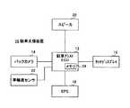
図1は、本発明の一実施形態の車両に搭載される駐車支援装置10のシステム構成図を示す。同図中、駐車支援装置10は、車庫入れ駐車や縦列駐車等の車両駐車時に、車両を駐車すべき道路路面上の駐車枠の白線(縁石またはガードレール等を含む)を目標駐車位置として認識し、また、駐車枠の車幅方向の白線に対する車両の傾き角度を計算する演算制御と、車内に搭載された表示モニタの表示画面に映し出された車両周辺画像上に車幅延長線や予想進路線、駐車枠と車両のアイコンを合成表示するガイドモニタ制御を行う。上記の演算制御及びガイドモニタ制御を合わせて駐車アシスト制御と称す。 FIG. 1 is a system configuration diagram of a
図1に示す如く、駐車支援装置10は、駐車アシスト用電子制御ユニット(以下、駐車アシストECUと称す)12を備えており、駐車アシストECU12により制御される。駐車アシストECU12には、バックカメラ14が接続されている。バックカメラ14は、車体後部中央に配設されており、車両後方に所定角範囲で広がる領域を撮影する。バックカメラ14は、その光軸が予め車体に対して所定方向を向くように取り付けられている。バックカメラ14の撮影した車両後方周辺の画像情報は、駐車アシストECU12に供給される。 As shown in FIG. 1, the
駐車アシストECU12には、また、タッチディスプレイ16が接続されている。タッチディスプレイ16は、車両運転者が視認可能かつ操作可能な位置(例えばインパネ中央)に配設されている。駐車アシストECU12は、例えば車両のシフトポジションが後退位置にある場合に、バックカメラ14による実画像をタッチディスプレイ16に表示させる。タッチディスプレイ16は、駐車アシストECU12の指令に従ってバックカメラ14による車両後方周辺を表示画面に映し出す。また、タッチディスプレイ16は、駐車アシストECU12の指令に従って駐車アシスト制御のための駐車枠と車両のアイコンや補助線等を、バックカメラ14による実画像上に重畳して合成表示する。 A
タッチディスプレイ16には、車両運転者による操作が可能な感圧式や温感式等のタッチ操作部が設けられる。タッチ操作部は、駐車アシストECU12の指令に従って表示画面上に表示される。駐車アシストECU12は、タッチ操作部への車両運転者のタッチ操作を検知し、かかるタッチ操作部の内容に応じた処理を実行する。なお、タッチ操作部には、駐車アシスト制御として車庫入れ駐車モードを開始するためのスイッチや縦列駐車モードを開始するためのスイッチが含まれる。 The
駐車アシストECU12には、また、電動パワーステアリング装置(以下、EPSと称す)18が接続されている。EPS18は、車両運転者によるステアリング操作によりステアリングシャフトに加わる操舵トルクを検出するトルクセンサと、車輪舵角に対応するステアリングシャフトの舵角を検出する舵角センサと、ステアリングシャフトにトルクを付与する電動モータを備えている。EPS18は、運転者のステアリング操作時にその操舵トルクをアシストするトルクを電動モータに発生させる。 An electric power steering device (hereinafter referred to as EPS) 18 is also connected to the parking assist ECU 12. The
EPS18は、検出したステアリングシャフトの舵角情報を駐車アシストECU12へ供給する。駐車アシストECU12は、駐車アシスト制御の実行時に、後述の如くステアリングシャフトが実現すべき目標舵角をEPS18へ供給する。EPS18は、駐車アシストECU12からの目標舵角の供給により、駐車アシスト制御のためのトルクを電動モータに発生させる。 The
駐車アシストECU12には、また、スピーカ20が接続されている。スピーカ20は、駐車アシストECU12の指令に従って車内乗員へ向けて音声を出力する装置である。駐車アシストECU12は、適当なタイミングでスピーカ20から適切な音声が出力されるようにスピーカ20に対して指令を行う。 A
駐車アシストECU12には、更に、車輪速センサ22が接続されている。車輪速センサ22は車両の各車輪の車輪速を検出している。また、駐車アシストECU12は、データの読み出し、書き込みが可能なメモリ24を内蔵している。メモリ24は、過去に認識した駐車枠の白線位置等を記憶する。メモリ24に記憶された情報は、駐車アシスト制御が完了した際に消去される。 A
以下、本実施例の駐車支援装置10の動作について説明する。 Hereinafter, operation | movement of the
図2は、駐車アシストECU12が実行する制御ルーチンの一実施形態のフローチャートを示す。この処理は車両のシフトポジションが後退位置に移行することで開始される。 FIG. 2 shows a flowchart of an embodiment of a control routine executed by the parking assist ECU 12. This process is started when the vehicle shift position shifts to the reverse position.
図2において、ステップS10では、縦列駐車モードであるか否かを判別する。なお、縦列駐車モードまたは車庫入れ駐車モードはタッチディスプレイ16のスイッチで指定される。ここで、縦列駐車モードと判別されると、ステップS12で縦列案内を実施し、白線認識処理を行うためにステップS14に進む。なお、縦列案内では、車両を初期位置まで移動させ、第1旋回を指示し、これに続く第2旋回を指示するための位置合わせ線及び車幅延長線や予想進路線をタッチディスプレイ16に合成表示するとともに音声ガイドを行う。 In FIG. 2, it is discriminate | determined by step S10 whether it is parallel parking mode. Note that the parallel parking mode or the garage parking mode is designated by a switch of the
ステップS14では、駐車枠の白線(縁石またはガードレール等を含む)を認識できたか否かを判別する。駐車枠の白線即ち目標駐車位置を認識できた場合にはステップS16で白線位置をメモリ24に記憶する。一方、駐車枠の白線を認識できない場合にはステップS18で過去に駐車枠の白線を認識しているか否かを判別する。過去に駐車枠の白線を認識して白線位置をメモリ24に記憶している場合には、ステップS20で最後に認識した駐車枠の白線位置を基準にしてEPS18の舵角センサと車輪速センサ22の計測値を基に現在の駐車枠の白線位置を推定する。過去に駐車枠の白線を認識していない場合にはステップS14に戻る。 In step S14, it is determined whether or not the white line (including the curbstone or guardrail) of the parking frame has been recognized. If the white line of the parking frame, that is, the target parking position can be recognized, the white line position is stored in the memory 24 in step S16. On the other hand, if the white line of the parking frame cannot be recognized, it is determined in step S18 whether the white line of the parking frame has been recognized in the past. When the white line position of the parking frame is recognized in the past and the white line position is stored in the memory 24, the steering angle sensor and the
上記のステップS16またはS20を実行したのち、ステップS22で第2旋回を行っているか否かを判別し、第2旋回中でなければステップS12に進む。第2旋回中であればステップS24で駐車枠の車幅方向の白線に対する車両の傾き角度を計算し、タッチディスプレイ16に駐車枠のアイコンに対し車両のアイコンを上記傾き角度をもって合成表示する。 After executing step S16 or S20 described above, it is determined in step S22 whether or not the second turn is being performed. If the second turn is not being performed, the process proceeds to step S12. If the vehicle is in the second turn, the inclination angle of the vehicle with respect to the white line in the vehicle width direction of the parking frame is calculated in step S24, and the vehicle icon is synthesized and displayed on the
次に、ステップS26で車両が駐車枠内に入って駐車が完了したか否かを判別し、駐車が完了していない場合にはステップS12に進み、駐車が完了していればステップS40に進む。 Next, in step S26, it is determined whether or not the vehicle has entered the parking frame and the parking has been completed. If the parking has not been completed, the process proceeds to step S12. If the parking has been completed, the process proceeds to step S40. .
ステップS10で縦列駐車モードでなく車庫入れ駐車モードと判別されると、ステップS30で車庫入れ案内を実施し、ステップS32で白線認識処理を実施する。なお、車庫入れ案内では、車幅延長線や予想進路線をタッチディスプレイ16にグラフィック表示するとともに音声ガイドを行う。 If it is determined in step S10 that the parking mode is not the parallel parking mode, the garage entry guidance is executed in step S30, and the white line recognition process is executed in step S32. In the garage entry guidance, the vehicle width extension line and the predicted route are graphically displayed on the
ステップS32の白線認識処理はステップS14〜S20と同一の処理である。つまり、駐車枠の白線を認識できた場合には白線位置を記憶し、駐車枠の白線を認識できない場合には、最後に認識した駐車枠の白線位置を基準にしてEPS18の舵角センサと車輪速センサ22の計測値を基に現在の駐車枠の白線位置を推定する。 The white line recognition process of step S32 is the same process as steps S14 to S20. That is, if the white line of the parking frame can be recognized, the position of the white line is stored. If the white line of the parking frame cannot be recognized, the rudder angle sensor and wheels of the
こののち、ステップS34で駐車枠の車幅方向の白線つまり目標駐車位置に対する車両の傾き角度を計算し、タッチディスプレイ16に駐車枠のアイコンに対し車両のアイコンを上記傾き角度をもって合成表示する。 After that, in step S34, the white angle of the parking frame in the vehicle width direction, that is, the inclination angle of the vehicle with respect to the target parking position is calculated, and the vehicle icon is synthesized and displayed on the
次に、ステップS36で車両が駐車枠内に入って駐車が完了したか否かを判別し、駐車が完了していない場合にはステップS20に進み、駐車が完了していればステップS40に進む。 Next, in step S36, it is determined whether or not the vehicle has entered the parking frame and the parking has been completed. If the parking has not been completed, the process proceeds to step S20. If the parking has been completed, the process proceeds to step S40. .
ステップS40では、駐車枠の車幅方向の白線に対する車両の傾き角度が所定角度以上であり、かつ、車両のシフトポジションが前進位置で有るか否かを判別し、この条件を満足した場合はステップS42に進み、駐車枠の車幅方向の白線に対する車両の傾き角度に応じてブザー音の周波数を変えて鳴らす。 In step S40, it is determined whether or not the inclination angle of the vehicle with respect to the white line in the vehicle width direction of the parking frame is equal to or greater than a predetermined angle and the shift position of the vehicle is the forward position. If this condition is satisfied, step S40 is performed. Proceeding to S42, the buzzer sound is generated by changing the frequency of the buzzer sound according to the inclination angle of the vehicle with respect to the white line in the vehicle width direction of the parking frame.
ここでは、シフトポジションが前進位置となったときに、上記傾き角度が所定角度以上であれば、例えば周波数500Hzでブザー音を鳴らし、その後、車両が前進して駐車枠の車幅方向の白線に対する車両の傾き角度が小さくなるにつれブザー音の周波数を上げ(もしくは下げ)、運転者に車両の傾きの解消度合いを知らせる。 Here, when the shift position becomes the forward position, if the tilt angle is equal to or greater than a predetermined angle, for example, a buzzer is sounded at a frequency of 500 Hz, and then the vehicle moves forward and the white line in the vehicle width direction of the parking frame. As the vehicle tilt angle decreases, the frequency of the buzzer sound is increased (or decreased) to inform the driver of the degree of cancellation of the vehicle tilt.
図3に、車庫入れ駐車モードで駐車完了した時点のタッチディスプレイ16の表示例を示す。同図中、タッチディスプレイ16にはバックカメラ14で撮影された実画像が表示されるとともに、駐車枠のアイコン30に対し車両のアイコン32が計算された傾き角度をもって合成表示されている。なお、図3では、駐車枠の車幅方向の白線をタッチディスプレイ16の縦軸と平行に配置することで駐車枠のアイコン30を基準とし、車両のアイコン32を傾けて表示しているが、車両のアイコン32を基準として駐車枠のアイコン30を傾けて表示することも可能である。 FIG. 3 shows a display example of the
ところで、駐車アシストECU12は、以下に説明する経路誘導制御を行うものであっても良い。この場合は経路誘導後の微調整を手動で行うことができる。 Incidentally, the parking assist
図4は、車庫入れ駐車時における目標駐車位置までの誘導経路を表した図を示す。車庫入れ駐車モードにおいて、駐車枠の白線即ち目標駐車位置までの誘導経路の計算は、自車両の最小旋回半径および自車両の現在位置とその目標駐車位置との相対位置関係から定まる所定の幾何学的な位置条件を満たす場合に、経路として順に(1)所定距離の直進後退区間、(2)クロソイドによる舵角の切り増し区間、(3)舵角固定による定常円旋回区間、(4)クロソイドによる舵角の切り戻し区間、及び(5)所定距離の直進後退区間の各区間が適切に形成されるように上記の相対位置関係に基づいて行われる。但し、経路初期の直進後退区間は全く形成されなくてもよい。 FIG. 4 is a diagram showing a guide route to a target parking position at the time of parking in a garage. In the garage parking mode, the calculation of the guidance route to the white line of the parking frame, that is, the target parking position is based on a predetermined geometry determined from the minimum turning radius of the host vehicle and the relative position relationship between the current position of the host vehicle and the target parking position. (1) Straight forward and backward section of a predetermined distance, (2) Steering angle increase section by clothoid, (3) Steady circular turning section by fixed steering angle, (4) Clothoid This is performed based on the above relative positional relationship so that each of the steering angle switching back section and the (5) straight forward and backward section of a predetermined distance is appropriately formed. However, the straight forward / backward section at the beginning of the route may not be formed at all.
また、図5は、縦列駐車時における目標駐車位置までの誘導経路を表した図を示す。縦列駐車モードにおいて、駐車枠の白線即ち目標駐車位置までの誘導経路の計算は、自車両の最小旋回半径、及び、自車両の現在位置とその目標駐車位置との相対位置関係から定まる所定の幾何学的な位置条件を満たす場合に、経路として第1旋回の円と第2旋回の円が接する状態が適切に形成されるように上記の相対位置関係に基づいて行われる。 Moreover, FIG. 5 shows the figure showing the guidance path | route to the target parking position at the time of parallel parking. In the parallel parking mode, the calculation of the guidance route to the white line of the parking frame, that is, the target parking position, is a predetermined geometry determined from the minimum turning radius of the host vehicle and the relative positional relationship between the current position of the host vehicle and the target parking position. When the geometrical position condition is satisfied, the process is performed based on the above relative positional relationship so that a state in which the first turning circle and the second turning circle are in contact with each other is appropriately formed as a path.
なお、ステップS14,S16が請求項記載の認識手段に対応し、ステップS20が推定手段に対応し、ステップS24,S34が算出手段に対応し、ステップS24,S34が合成表示手段に対応し、ステップS42が報知手段に対応する。 Steps S14 and S16 correspond to the recognition means described in the claims, step S20 corresponds to the estimation means, steps S24 and S34 correspond to the calculation means, steps S24 and S34 correspond to the composite display means, S42 corresponds to the notification means.
10 駐車支援装置
12 駐車アシスト用電子制御ユニット(駐車アシストECU)
14 バックカメラ
16 タッチディスプレイ
18 電動パワーステアリング装置(EPS)
20 スピーカ
22 車輪速センサ10
14
20
Claims (5)
Translated fromJapanese前記駐車枠に対する車両の傾き度合いを算出する算出手段を備え、
車両が駐車枠内に入って駐車完了後、シフトポジションが前進位置である場合に、駐車枠の車幅方向に対する車両の傾き角度が所定値以上のときに、音声により報知を行う報知手段を
有することを特徴とする駐車支援装置。A recognition means for recognizing aparking frame from an image taken by a camera;
A calculating meansfor calculating a degree of inclination of the vehicle with respect to theparking frame;
When the vehicle enters the parking frame and the parking is completed, when the shift position is the forward position, an informing means for informing by voice when the inclination angle of the vehicle with respect to the vehicle width direction of the parking frame is equal to or greater than a predetermined value < A parking assistance device comprising:
前記報知手段は、車両が前進して駐車枠に対する車両の傾き角度が小さくなるにつれブザー音の周波数を上げもしくは下げることを特徴とする駐車支援装置。In the parking assistance device according to claim 1,
The informing means raises or lowers the frequency of the buzzer sound as the vehicle moves forward and the inclination angle of the vehicle with respect to the parking frame decreases .
駐車枠までの経路誘導を行う経路誘導手段を
有することを特徴とする駐車支援装置。In the parking assistance device according to claim 1,
A parking assistance device comprising route guidance means for guiding a route to aparking frame .
前記画像から駐車枠が認識されないときに、過去に認識された駐車枠と、車両の操舵角及び車輪速の履歴から駐車枠を推定する推定手段を When the parking frame is not recognized from the image, an estimation means for estimating the parking frame from the history of the parking frame recognized in the past and the steering angle and wheel speed of the vehicle.
有することを特徴とする駐車支援装置。A parking assistance device comprising:
前記画像に前記推定された駐車枠に対する車両の傾き度合いを合成表示する合成表示手段を Composite display means for combining and displaying the degree of inclination of the vehicle with respect to the estimated parking frame on the image.
有することを特徴とする駐車支援装置。A parking assistance device comprising:
Priority Applications (1)
| Application Number | Priority Date | Filing Date | Title |
|---|---|---|---|
| JP2004275194AJP4193780B2 (en) | 2004-09-22 | 2004-09-22 | Parking assistance device |
Applications Claiming Priority (1)
| Application Number | Priority Date | Filing Date | Title |
|---|---|---|---|
| JP2004275194AJP4193780B2 (en) | 2004-09-22 | 2004-09-22 | Parking assistance device |
Publications (2)
| Publication Number | Publication Date |
|---|---|
| JP2006088827A JP2006088827A (en) | 2006-04-06 |
| JP4193780B2true JP4193780B2 (en) | 2008-12-10 |
Family
ID=36230209
Family Applications (1)
| Application Number | Title | Priority Date | Filing Date |
|---|---|---|---|
| JP2004275194AExpired - Fee RelatedJP4193780B2 (en) | 2004-09-22 | 2004-09-22 | Parking assistance device |
Country Status (1)
| Country | Link |
|---|---|
| JP (1) | JP4193780B2 (en) |
Cited By (1)
| Publication number | Priority date | Publication date | Assignee | Title |
|---|---|---|---|---|
| JP2011016514A (en)* | 2009-06-09 | 2011-01-27 | Denso Corp | Parking aid system |
Families Citing this family (7)
| Publication number | Priority date | Publication date | Assignee | Title |
|---|---|---|---|---|
| US7970535B2 (en) | 2006-07-04 | 2011-06-28 | Denso Corporation | Drive assist system |
| JP4863791B2 (en)* | 2006-07-05 | 2012-01-25 | アルパイン株式会社 | Vehicle peripheral image generation apparatus and image switching method |
| JP4967604B2 (en)* | 2006-11-01 | 2012-07-04 | スズキ株式会社 | Parking assistance system |
| JP5083254B2 (en)* | 2009-03-18 | 2012-11-28 | 株式会社デンソー | Parking result display system |
| JP5516992B2 (en)* | 2010-11-30 | 2014-06-11 | アイシン精機株式会社 | Parking position adjustment device |
| JP5987948B2 (en)* | 2015-04-22 | 2016-09-07 | 三菱自動車工業株式会社 | Driving assistance device |
| JP2020015372A (en)* | 2018-07-24 | 2020-01-30 | 株式会社デンソーテン | Image processing device and image processing method |
- 2004
- 2004-09-22JPJP2004275194Apatent/JP4193780B2/ennot_activeExpired - Fee Related
Cited By (2)
| Publication number | Priority date | Publication date | Assignee | Title |
|---|---|---|---|---|
| JP2011016514A (en)* | 2009-06-09 | 2011-01-27 | Denso Corp | Parking aid system |
| US8542129B2 (en) | 2009-06-09 | 2013-09-24 | Denso Corporation | Parking aid system |
Also Published As
| Publication number | Publication date |
|---|---|
| JP2006088827A (en) | 2006-04-06 |
Similar Documents
| Publication | Publication Date | Title |
|---|---|---|
| JP4235026B2 (en) | Parking assistance device | |
| JP4466200B2 (en) | Parking assistance device | |
| JP4235051B2 (en) | Parking assistance device | |
| US7099758B2 (en) | Parking assist apparatus | |
| KR100788027B1 (en) | Parking assist apparatus for vehicle | |
| JP4900174B2 (en) | Parking assistance device, parking assistance method, and computer program | |
| JP4661639B2 (en) | Driving assistance device | |
| JP2003300443A (en) | Parking assistance device | |
| JP6318204B2 (en) | Parking exit support device | |
| KR20090040024A (en) | How to turn on the car parking aid automatically | |
| JP5082905B2 (en) | Parking assistance device, parking assistance method, and computer program | |
| JP4353014B2 (en) | Parking assistance device | |
| JP4507872B2 (en) | Parking assistance device | |
| JP4193780B2 (en) | Parking assistance device | |
| JP2008213741A (en) | Driving assisting device | |
| JP2014024462A (en) | Parking support device | |
| JP4941383B2 (en) | Parking assistance device, parking assistance method, and computer program | |
| JP6040766B2 (en) | Parking assistance device | |
| JP4416000B2 (en) | Parking assistance device | |
| JP6373916B2 (en) | Parking exit support device | |
| JP4110937B2 (en) | Parking assistance device | |
| JP2018184046A (en) | Parking support device | |
| JP2006123606A (en) | Parking assistance device | |
| JP4136982B2 (en) | Parking support method and parking support device | |
| JP5136291B2 (en) | Parking assistance device and parking assistance method |
Legal Events
| Date | Code | Title | Description |
|---|---|---|---|
| A621 | Written request for application examination | Free format text:JAPANESE INTERMEDIATE CODE: A621 Effective date:20061030 | |
| A977 | Report on retrieval | Free format text:JAPANESE INTERMEDIATE CODE: A971007 Effective date:20080530 | |
| A131 | Notification of reasons for refusal | Free format text:JAPANESE INTERMEDIATE CODE: A131 Effective date:20080603 | |
| A521 | Request for written amendment filed | Free format text:JAPANESE INTERMEDIATE CODE: A523 Effective date:20080804 | |
| TRDD | Decision of grant or rejection written | ||
| A01 | Written decision to grant a patent or to grant a registration (utility model) | Free format text:JAPANESE INTERMEDIATE CODE: A01 Effective date:20080902 | |
| A01 | Written decision to grant a patent or to grant a registration (utility model) | Free format text:JAPANESE INTERMEDIATE CODE: A01 | |
| A61 | First payment of annual fees (during grant procedure) | Free format text:JAPANESE INTERMEDIATE CODE: A61 Effective date:20080915 | |
| FPAY | Renewal fee payment (event date is renewal date of database) | Free format text:PAYMENT UNTIL: 20111003 Year of fee payment:3 | |
| FPAY | Renewal fee payment (event date is renewal date of database) | Free format text:PAYMENT UNTIL: 20111003 Year of fee payment:3 | |
| FPAY | Renewal fee payment (event date is renewal date of database) | Free format text:PAYMENT UNTIL: 20121003 Year of fee payment:4 | |
| FPAY | Renewal fee payment (event date is renewal date of database) | Free format text:PAYMENT UNTIL: 20131003 Year of fee payment:5 | |
| LAPS | Cancellation because of no payment of annual fees |