JP4191884B2 - Image processing method, image processing apparatus, and image photographing apparatus - Google Patents
Image processing method, image processing apparatus, and image photographing apparatusDownload PDFInfo
- Publication number
- JP4191884B2 JP4191884B2JP2000248280AJP2000248280AJP4191884B2JP 4191884 B2JP4191884 B2JP 4191884B2JP 2000248280 AJP2000248280 AJP 2000248280AJP 2000248280 AJP2000248280 AJP 2000248280AJP 4191884 B2JP4191884 B2JP 4191884B2
- Authority
- JP
- Japan
- Prior art keywords
- value
- image
- pixel
- dispersion
- range
- Prior art date
- Legal status (The legal status is an assumption and is not a legal conclusion. Google has not performed a legal analysis and makes no representation as to the accuracy of the status listed.)
- Expired - Fee Related
Links
Images


Classifications
- G—PHYSICS
- G06—COMPUTING OR CALCULATING; COUNTING
- G06T—IMAGE DATA PROCESSING OR GENERATION, IN GENERAL
- G06T5/00—Image enhancement or restoration
- G06T5/70—Denoising; Smoothing
- A—HUMAN NECESSITIES
- A61—MEDICAL OR VETERINARY SCIENCE; HYGIENE
- A61B—DIAGNOSIS; SURGERY; IDENTIFICATION
- A61B5/00—Measuring for diagnostic purposes; Identification of persons
- A61B5/05—Detecting, measuring or recording for diagnosis by means of electric currents or magnetic fields; Measuring using microwaves or radio waves
- A61B5/055—Detecting, measuring or recording for diagnosis by means of electric currents or magnetic fields; Measuring using microwaves or radio waves involving electronic [EMR] or nuclear [NMR] magnetic resonance, e.g. magnetic resonance imaging
- G—PHYSICS
- G06—COMPUTING OR CALCULATING; COUNTING
- G06T—IMAGE DATA PROCESSING OR GENERATION, IN GENERAL
- G06T5/00—Image enhancement or restoration
- G06T5/20—Image enhancement or restoration using local operators
- G—PHYSICS
- G06—COMPUTING OR CALCULATING; COUNTING
- G06T—IMAGE DATA PROCESSING OR GENERATION, IN GENERAL
- G06T2207/00—Indexing scheme for image analysis or image enhancement
- G06T2207/10—Image acquisition modality
- G06T2207/10072—Tomographic images
- G06T2207/10088—Magnetic resonance imaging [MRI]
- G—PHYSICS
- G06—COMPUTING OR CALCULATING; COUNTING
- G06T—IMAGE DATA PROCESSING OR GENERATION, IN GENERAL
- G06T2207/00—Indexing scheme for image analysis or image enhancement
- G06T2207/20—Special algorithmic details
- G06T2207/20172—Image enhancement details
- G06T2207/20192—Edge enhancement; Edge preservation
- G—PHYSICS
- G06—COMPUTING OR CALCULATING; COUNTING
- G06T—IMAGE DATA PROCESSING OR GENERATION, IN GENERAL
- G06T2207/00—Indexing scheme for image analysis or image enhancement
- G06T2207/30—Subject of image; Context of image processing
- G06T2207/30004—Biomedical image processing
Landscapes
- Physics & Mathematics (AREA)
- Engineering & Computer Science (AREA)
- Health & Medical Sciences (AREA)
- General Physics & Mathematics (AREA)
- Theoretical Computer Science (AREA)
- Life Sciences & Earth Sciences (AREA)
- Nuclear Medicine, Radiotherapy & Molecular Imaging (AREA)
- Pathology (AREA)
- Molecular Biology (AREA)
- Biophysics (AREA)
- High Energy & Nuclear Physics (AREA)
- Biomedical Technology (AREA)
- Heart & Thoracic Surgery (AREA)
- Medical Informatics (AREA)
- Radiology & Medical Imaging (AREA)
- Surgery (AREA)
- Animal Behavior & Ethology (AREA)
- General Health & Medical Sciences (AREA)
- Public Health (AREA)
- Veterinary Medicine (AREA)
- Image Processing (AREA)
- Magnetic Resonance Imaging Apparatus (AREA)
Description
Translated fromJapanese【0001】
【発明の属する技術分野】
本発明は、画像処理方法および装置、記録媒体並びに画像撮影装置に関し、特に、画像のノイズ(noise)を除去する画像処理方法および装置、そのような画像処理機能をコンピュータに実現させるプログラムを記録した媒体、並びに、そのような画像処理装置を備えた画像撮影装置に関する。
【0002】
【従来の技術】
磁気共鳴撮影(MRI:Magnetic Resonance Imaging)装置では、マグネットシステム(magnet system)の内部空間、すなわち、静磁場を形成した空間に撮影の対象を搬入し、勾配磁場および高周波磁場を印加して対象内に磁気共鳴信号を発生させ、その受信信号に基づいて断層像を生成(再構成)する。
【0003】
断層像の細部構造をより良く観察できるようにするために、画像のノイズ(noise)を除去するフィルタリング(filtering)が行われる。フィルタリングはローパスフィルタリング(low−pass filtering)を基本とするが、それだけでは画像の鮮鋭度(シャープネス:sharpness)が低下するので、シャープネスを確保するための処理を付加したフィルタリングが採用される。
【0004】
シャープネスを確保するための処理を付加したフィルタリングでは、元画像において注目画素を含む局所的な領域を複数の態様で設定し、各態様の局所的な領域ごとに画素値の分散を計算し、最も小さい分散が得られた領域の画素値の平均値を求めて、それを注目画素の新たな画素値とするようにしている。
【0005】
【発明が解決しようとする課題】
上記のようなフィルタリングは、各態様の局所領域について全て画素値の分散を求めてからその最小値を抽出するので、フィルタリングの処理速度が遅くなる。
【0006】
そこで、本発明の課題は、フィルタリングを能率良く行う画像処理方法および装置、そのような画像処理機能をコンピュータに実現させるプログラムを記録した媒体、並びに、そのような画像処理装置を備えた画像撮影装置を実現することである。
【0007】
【課題を解決するための手段】
(1)上記の課題を解決するための1つの観点での発明は、元画像において注目画素を含む局所的な領域を複数の態様で設定し、画素値の分散を求めてその値が予め定めた範囲に入るか否かを判定することを前記複数の態様の領域について順次に行い、前記分散の値が最初に前記範囲に入った領域の画素値の平均値を前記注目画素の新たな画素値として画像を形成する、ことを特徴とする画像処理方法である。
【0008】
この観点での発明では、画素値の分散を求めてその値が予め定めた範囲に入るか否かを判定することを複数の態様の領域について順次に行い、分散の値が最初に範囲に入った領域の画素値の平均値を注目画素の新たな画素値とするので、分散の計算回数を減らすことができ、フィルタリングの能率が上がる。
【0009】
(2)上記の課題を解決するための他の観点での発明は、前記領域は1次元的領域である、ことを特徴とする(1)に記載の画像処理方法である。
この観点での発明では、(1)に加えて、分散の計算領域を1次元的領域としたので、エッジ状の構造を明確化するフィルタリングを行うことができる。
【0010】
(3)上記の課題を解決するための他の観点での発明は、前記範囲の上限は前記元画像のノイズの分散である、ことを特徴とする(1)または(2)に記載の画像処理方法である。
【0011】
この観点での発明では、(1)または(2)に加えて、範囲の上限を元画像のノイズの分散としたので、元画像の構造に適合したフィルタリングを行うことができる。
【0012】
(4)上記の課題を解決するための他の観点での発明は、前記複数の態様の領域の分散の値がいずれも前記範囲に入らないときは前記分散の値が最も小さい領域の画素値の平均値を前記注目画素の新たな画素値として画像を形成する、ことを特徴とする(1)ないし(3)のうちのいずれか1つに記載の画像処理方法である。
【0013】
この観点での発明では、(1)ないし(3)のうちのいずれか1つに加えて、分散の値がいずれも範囲に入らないときは分散の値が最も小さい領域の画素値の平均値を注目画素の新たな画素値とするので、相対的に最も矛盾が少ない画素値を得ることができる。
【0014】
(5)上記の課題を解決するための他の観点での発明は、元画像において注目画素を含む局所的な領域を複数の態様で設定する領域設定手段と、画素値の分散を求めてその値が予め定めた範囲に入るか否かを判定することを前記複数の態様の領域について順次に行う分散計算/判定手段と、前記分散の値が最初に前記範囲に入った領域の画素値の平均値を前記注目画素の新たな画素値として画像を形成する画像形成手段と、を具備することを特徴とする画像処理装置である。
【0015】
この観点での発明では、画素値の分散を求めてその値が予め定めた範囲に入るか否かを判定することを複数の態様の領域について順次に行い、分散の値が最初に範囲に入った領域の画素値の平均値を注目画素の新たな画素値とするので、分散の計算回数を減らすことができ、フィルタリングの能率が上がる。
【0016】
(6)上記の課題を解決するための他の観点での発明は、前記領域は1次元的領域である、ことを特徴とする(5)に記載の画像処理装置である。
この観点での発明では、(5)に加えて、分散の計算領域を1次元的領域としたので、エッジ状の構造を明確化するフィルタリングを行うことができる。
【0017】
(7)上記の課題を解決するための他の観点での発明は、前記範囲の上限は前記元画像のノイズの分散である、ことを特徴とする(5)または(6)に記載の画像処理装置である。
【0018】
この観点での発明では、(5)または(6)に加えて、範囲の上限を元画像のノイズの分散としたので、元画像の構造に適合したフィルタリングを行うことができる。
【0019】
(8)上記の課題を解決するための他の観点での発明は、前記複数の態様の領域の分散の値がいずれも前記範囲に入らないときは前記分散の値が最も小さい領域の画素値の平均値を前記注目画素の新たな画素値として画像を形成する他の画像形成手段、を具備することを特徴とする(5)ないし(7)のうちのいずれか1つに記載の画像処理装置である。
【0020】
この観点での発明では、(5)ないし(7)のうちのいずれか1つに加えて、分散の値がいずれも範囲に入らないときは分散の値が最も小さい領域の画素値の平均値を注目画素の新たな画素値とするので、相対的に最も矛盾が少ない画素値を得ることができる。
【0021】
(9)上記の課題を解決するための他の観点での発明は、元画像において注目画素を含む局所的な領域を複数の態様で設定し、画素値の分散を求めてその値が予め定めた範囲に入るか否かを判定することを前記複数の態様の領域について順次に行い、前記分散の値が最初に前記範囲に入った領域の画素値の平均値を前記注目画素の新たな画素値として画像を形成する、機能をコンピュータに実現させるプログラムをコンピュータにより読み取り可能なように記録したことを特徴とする記録媒体である。
【0022】
この観点での発明では、記録媒体に記録されたプログラムが、画素値の分散を求めてその値が予め定めた範囲に入るか否かを判定することを複数の態様の領域について順次に行い、分散の値が最初に範囲に入った領域の画素値の平均値を注目画素の新たな画素値とする、機能をコンピュータに実現させるので、分散の計算回数を減らすことができ、フィルタリングの能率が上がる。
【0023】
(10)上記の課題を解決するための他の観点での発明は、前記領域は1次元的領域である、ことを特徴とする(9)に記載の記録媒体である。
この観点での発明では、(9)に加えて、分散の計算領域を1次元的領域としたので、エッジ状の構造を明確化するフィルタリングを行うことができる。
【0024】
(11)上記の課題を解決するための他の観点での発明は、前記範囲の上限は前記元画像のノイズの分散である、ことを特徴とする(9)または(10)に記載の記録媒体である。
【0025】
この観点での発明では、(9)または(10)に加えて、範囲の上限を元画像のノイズの分散としたので、元画像の構造に適合したフィルタリングを行うことができる。
【0026】
(12)上記の課題を解決するための他の観点での発明は、前記複数の態様の領域の分散の値がいずれも前記範囲に入らないときは前記分散の値が最も小さい領域の画素値の平均値を前記注目画素の新たな画素値として画像を形成する、機能をコンピュータに実現させるプログラムをコンピュータにより読み取り可能なように記録したことを特徴とする(9)ないし(11)のうちのいずれか1つに記載の記録媒体である。
【0027】
この観点での発明では、(9)ないし(11)のうちのいずれか1つに加えて、分散の値がいずれも範囲に入らないときは分散の値が最も小さい領域の画素値の平均値を注目画素の新たな画素値とする、機能をコンピュータに実現させるので、相対的に最も矛盾が少ない画素値を得ることができる。
【0028】
(13)上記の課題を解決するための他の観点での発明は、対象から信号を収集する信号収集手段と、前記収集した信号に基づいて元画像を生成する元画像生成手段と、前記元画像において注目画素を含む局所的な領域を複数の態様で設定する領域設定手段と、画素値の分散を求めてその値が予め定めた範囲に入るか否かを判定することを前記複数の態様の領域について順次に行う分散計算/判定手段と、前記分散の値が最初に前記範囲に入った領域の画素値の平均値を前記注目画素の新たな画素値として画像を形成する画像形成手段と、を具備することを特徴とする画像撮影装置である。
【0029】
この観点での発明では、撮影した元画像の画素値の分散を求めて、その値が予め定めた範囲に入るか否かを判定することを複数の態様の領域について順次に行い、分散の値が最初に範囲に入った領域の画素値の平均値を注目画素の新たな画素値とするので、分散の計算回数を減らすことができ、フィルタリングの能率が上がる。
【0030】
(14)上記の課題を解決するための他の観点での発明は、前記領域は1次元的領域である、ことを特徴とする(13)に記載の画像撮影装置である。
この観点での発明では、(13)に加えて、分散の計算領域を1次元的領域としたので、エッジ状の構造を明確化するフィルタリングを行うことができる。
【0031】
(15)上記の課題を解決するための他の観点での発明は、前記範囲の上限は前記元画像のノイズの分散である、ことを特徴とする(13)または(14)に記載の画像撮影装置である。
【0032】
この観点での発明では、(13)または(14)に加えて、範囲の上限を元画像のノイズの分散としたので、元画像の構造に適合したフィルタリングを行うことができる。
【0033】
(16)上記の課題を解決するための他の観点での発明は、前記複数の態様の領域の分散の値がいずれも前記範囲に入らないときは前記分散の値が最も小さい領域の画素値の平均値を前記注目画素の新たな画素値として画像を形成する他の画像形成手段、を具備することを特徴とする(13)ないし(15)のうちのいずれか1つに記載の画像撮影装置である。
【0034】
この観点での発明では、(13)ないし(15)のうちのいずれか1つに加えて、分散の値がいずれも範囲に入らないときは分散の値が最も小さい領域の画素値の平均値を注目画素の新たな画素値とするので、相対的に最も矛盾が少ない画素値を得ることができる。
【0035】
(17)上記の課題を解決するための他の観点での発明は、前記信号は磁気共鳴信号である、ことを特徴とする(13)ないし(15)のうちのいずれか1つに記載の画像撮影装置である。
【0036】
この観点での発明では、フィルタリングを能率良く行う画像処理装置を備えた磁気共鳴撮影装置を実現することができる。
【0037】
【発明の実施の形態】
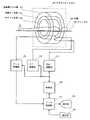
以下、図面を参照して本発明の実施の形態を詳細に説明する。なお、本発明は実施の形態に限定されるものではない。図1に画像撮影装置のブロック(block)図を示す。本装置は本発明の実施の形態の一例である。本装置の構成によって、本発明の装置に関する実施の形態の一例が示される。本装置の動作によって、本発明の方法に関する実施の形態の一例が示される。
【0038】
図1に示すように、本装置はマグネットシステム100を有する。マグネットシステム100は主磁場コイル(coil)部102、勾配コイル部106およびRF(radio frequency)コイル部108を有する。これら各コイル部は概ね円筒状の形状を有し、互いに同軸的に配置されている。マグネットシステム100の概ね円柱状の内部空間(ボア:bore)に、撮影の対象300がクレードル(cradle)500に搭載されて図示しない搬送手段により搬入および搬出される。
【0039】
主磁場コイル部102はマグネットシステム100の内部空間に静磁場を形成する。静磁場の方向は概ね対象300の体軸の方向に平行である。すなわちいわゆる水平磁場を形成する。主磁場コイル部102は例えば超伝導コイルを用いて構成される。なお、超伝導コイルに限らず常伝導コイル等を用いて構成しても良いのはもちろんである。
【0040】
勾配コイル部106は静磁場強度に勾配を持たせるための勾配磁場を生じる。発生する勾配磁場は、スライス(slice)勾配磁場、リードアウト(read out)勾配磁場およびフェーズエンコード(phase encode)勾配磁場の3種であり、これら3種類の勾配磁場に対応して勾配コイル部106は図示しない3系統の勾配コイルを有する。
【0041】
RFコイル部108は静磁場空間に対象300の体内のスピンを励起するための高周波磁場を形成する。以下、高周波磁場を形成することをRF励起信号の送信ともいう。RFコイル部108は、また、励起されたスピンが生じる電磁波すなわち磁気共鳴信号を受信する。
【0042】
RFコイル部108は図示しない送信用のコイルおよび受信用のコイルを有する。送信用のコイルおよび受信用のコイルは、同じコイルを兼用するかあるいはそれぞれ専用のコイルを用いる。
【0043】
勾配コイル部106には勾配駆動部130が接続されている。勾配駆動部130は勾配コイル部106に駆動信号を与えて勾配磁場を発生させる。勾配駆動部130は、勾配コイル部106における3系統の勾配コイルに対応して、図示しない3系統の駆動回路を有する。
【0044】
RFコイル部108にはRF駆動部140が接続されている。RF駆動部140はRFコイル部108に駆動信号を与えてRF励起信号を送信し、対象300の体内のスピンを励起する。
【0045】
RFコイル部108にはデータ収集部150が接続されている。データ収集部150はRFコイル部108が受信した受信信号を取り込み、それをビューデータ(view data)として収集する。
【0046】
勾配駆動部130、RF駆動部140およびデータ収集部150には制御部160が接続されている。制御部160は、勾配駆動部130ないしデータ収集部150をそれぞれ制御して撮影を遂行する。
【0047】
マグネットシステム100、勾配駆動部130、RF駆動部140、データ収集部150および制御部160からなる部分は、本発明における信号収集手段の実施の形態の一例である。
【0048】
データ収集部150の出力側はデータ処理部170に接続されている。データ処理部170は、例えばコンピュータ(computer)等を用いて構成される。データ処理部170は図示しないメモリ(memory)を有する。メモリはデータ処理部170用のプログラムおよび各種のデータを記憶している。本装置の機能は、データ処理部170がメモリに記憶されたプログラムを実行することによりを実現される。
【0049】
データ処理部170は、データ収集部150から取り込んだデータをメモリに記憶する。メモリ内にはデータ空間が形成される。データ空間は2次元フ−リエ(Fourier)空間を構成する。データ処理部170は、これら2次元フ−リエ空間のデータを2次元逆フ−リエ変換して対象300の画像を生成(再構成)する。以下、2次元フ−リエ空間をkスペース(k−space)ともいう。データ処理部170は、本発明における元画像生成手段の実施の形態の一例である。
【0050】
データ処理部170は、また、再構成した画像をフィルタリングする機能を有する。データ処理部170は、本発明の画像処理装置の実施の形態の一例である。データ処理部170のフィルタリング機能については後にあらためて説明する。
【0051】
データ処理部170は制御部160に接続されている。データ処理部170は制御部160の上位にあってそれを統括する。データ処理部170には表示部180および操作部190が接続されている。表示部180は、グラフィックディスプレー(graphic display)等で構成される。操作部190はポインティングデバイス(pointing device)を備えたキーボード(keyboard)等で構成される。
【0052】
表示部180は、データ処理部170から出力される再構成画像および各種の情報を表示する。操作部190は、操作者によって操作され、各種の指令や情報等をデータ処理部170に入力する。操作者は表示部180および操作部190を通じてインタラクティブ(interactive)に本装置を操作する。
【0053】
図2に、他の方式の画像撮影装置のブロック図を示す。本装置は本発明の実施の形態の一例である。本装置の構成によって、本発明の装置に関する実施の形態の一例が示される。本装置の動作によって、本発明の方法に関する実施の形態の一例が示される。
【0054】
図2に示す装置は、図1に示した装置とは方式を異にするマグネットシステム100’を有する。マグネットシステム100’以外は図1に示した装置と同様な構成になっており、同様な部分に同一の符号を付して説明を省略する。
【0055】
マグネットシステム100’は主磁場マグネット部102’、勾配コイル部106’およびRFコイル部108’を有する。これら主磁場マグネット部102’および各コイル部は、いずれも空間を挟んで互いに対向する1対のものからなる。また、いずれも概ね円盤状の形状を有し中心軸を共有して配置されている。マグネットシステム100’の内部空間(ボア)に、対象300がクレードル500に搭載されて図示しない搬送手段により搬入および搬出される。
【0056】
主磁場マグネット部102’はマグネットシステム100’の内部空間に静磁場を形成する。静磁場の方向は概ね対象300の体軸方向と直交する。すなわちいわゆる垂直磁場を形成する。主磁場マグネット部102’は例えば永久磁石等を用いて構成される。なお、永久磁石に限らず超伝導電磁石あるいは常伝導電磁石等を用いて構成しても良いのはもちろんである。
【0057】
勾配コイル部106’は静磁場強度に勾配を持たせるための勾配磁場を生じる。発生する勾配磁場は、スライス勾配磁場、リードアウト勾配磁場およびフェーズエンコード勾配磁場の3種であり、これら3種類の勾配磁場に対応して勾配コイル部106’は図示しない3系統の勾配コイルを有する。
【0058】
RFコイル部108’は静磁場空間に対象300の体内のスピンを励起するためのRF励起信号を送信する。RFコイル部108’は、また、励起されたスピンが生じる磁気共鳴信号を受信する。RFコイル部108’は図示しない送信用のコイルおよび受信用のコイルを有する。送信用のコイルおよび受信用のコイルは、同じコイルを兼用するかあるいはそれぞれ専用のコイルを用いる。
【0059】
マグネットシステム100’、勾配駆動部130、RF駆動部140、データ収集部150および制御部160からなる部分は、本発明における信号収集手段の実施の形態の一例である。
【0060】
図3に、磁気共鳴撮影に用いるパルスシーケンス(pulse sequence)の一例を示す。このパルスシーケンスは、グラディエントエコー(GRE:Gradient Echo)法のパルスシーケンスである。
【0061】
すなわち、(1)はGRE法におけるRF励起用のα°パルスのシーケンスであり、(2)、(3)、(4)および(5)は、同じくそれぞれ、スライス勾配Gs、リードアウト勾配Gr、フェーズエンコード勾配GpおよびグラディエントエコーMRのシーケンスである。なお、α°パルスは中心信号で代表する。パルスシーケンスは時間軸tに沿って左から右に進行する。
【0062】
同図に示すように、α°パルスによりスピンのα°励起が行われる。フリップアングル(flip angle)α°は90°以下である。このときスライス勾配Gsが印加され所定のスライスについての選択励起が行われる。
【0063】
α°励起後、フェーズエンコード勾配Gpによりスピンのフェーズエンコードが行われる。次に、リードアウト勾配Grにより先ずスピンをディフェーズ(dephase)し、次いでスピンをリフェーズ(rephase)して、グラディエントエコーMRを発生させる。グラディエントエコーMRの信号強度は、α°励起からエコータイム(echo time)TE後の時点で最大となる。グラディエントエコーMRはデータ収集部150によりビューデータとして収集される。
【0064】
このようなパルスシーケンスが周期TR(repetition time)で64〜512回繰り返される。繰り返しのたびにフェーズエンコード勾配Gpを変更し、毎回異なるフェーズエンコードを行う。これによって、kスペースを埋める64〜512ビューのビューデータが得られる。
【0065】
磁気共鳴撮影用パルスシーケンスの他の例を図4に示す。このパルスシーケンスは、スピンエコー(SE:Spin Echo)法のパルスシーケンスである。
【0066】
すなわち、(1)はSE法におけるRF励起用の90°パルスおよび180°パルスのシーケンスであり、(2)、(3)、(4)および(5)は、同じくそれぞれ、スライス勾配Gs、リードアウト勾配Gr、フェーズエンコード勾配GpおよびスピンエコーMRのシーケンスである。なお、90°パルスおよび180°パルスはそれぞれ中心信号で代表する。パルスシーケンスは時間軸tに沿って左から右に進行する。
【0067】
同図に示すように、90°パルスによりスピンの90°励起が行われる。このときスライス勾配Gsが印加され所定のスライスについての選択励起が行われる。90°励起から所定の時間後に、180°パルスによる180°励起すなわちスピン反転が行われる。このときもスライス勾配Gsが印加され、同じスライスについての選択的反転が行われる。
【0068】
90°励起とスピン反転の間の期間に、リードアウト勾配Grおよびフェーズエンコード勾配Gpが印加される。リードアウト勾配Grによりスピンのディフェーズが行われる。フェーズエンコード勾配Gpによりスピンのフェーズエンコードが行われる。
【0069】
スピン反転後、リードアウト勾配GrでスピンをリフェーズしてスピンエコーMRを発生させる。スピンエコーMRの信号強度は、90°励起からTE後の時点で最大となる。スピンエコーMRはデータ収集部150によりビューデータとして収集される。このようなパルスシーケンスが周期TRで64〜512回繰り返される。繰り返しのたびにフェーズエンコード勾配Gpを変更し、毎回異なるフェーズエンコードを行う。これによって、kスペースを埋める64〜512ビューのビューデータが得られる。
【0070】
なお、撮影に用いるパルスシーケンスはGRE法またはSE法に限るものではなく、例えば、FSE(Fast Spin Echo)法、ファーストリカバリFSE(Fast Recovery Fast Spin Echo)法、エコープラナー・イメージング(EPI:Echo Planar Imaging)等、他の適宜の技法のものであって良い。
【0071】
データ処理部170は、kスペースのビューデータを2次元逆フ−リエ変換して対象300の断層像を再構成する。再構成した画像はメモリに記憶し、また、表示部180で表示する。
【0072】
画像のノイズを除去するために、データ処理部170において画像のフィルタリングが行われる。フィルタリングは画像再構成の一環として行うようにしても良く、あるいは、再構成画像の観察結果に基づいて、操作者の選択により行うようにしても良い。
【0073】
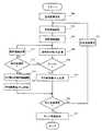
図5に、データ処理部170による画像フィルタリング動作のフローチャート(flow chart)を示す。同図に示すように、ステップ(step)500で、元画像における注目画素を指定する。注目画素とは、これからフィルタリングによって画素値を確定する画素であり、元画像中の1つの画素が指定される。最初の画素としては、例えば元画像の中央画素等が指定される。
【0074】
次に、ステップ502で、元画像中に局所領域を設定する。局所領域は注目画素を含む局所的な領域である。局所領域は例えば複数の画素の1次元的な連なりとして設定される。なお、局所領域の設定はこれに限るものではなく、適宜で良い。ステップ502の処理を行うデータ処理部170は、本発明における領域設定手段の実施の形態の一例である。
【0075】
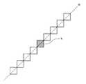
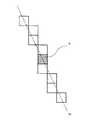
局所領域は複数の態様で設定される。局所領域の設定の態様の例を、図6ないし図9に示す。同図に示すように1つの態様では、図6に示すように、注目画素kを中心として垂直に連なる例えば7つの画素からなる領域が設定される。この局所領域を局所領域Aという。なお、画素数は7に限るものではなく適宜で良い。
【0076】
他の態様では、図7に示すように右上がりの45°方向に連なる7つの画素からなる局所領域B、図8に示すように水平に連なる7つの画素からなる局所領域C、および、図9に示すように左上がりの45°方向に連なる7つの画素からなる局所領域Dが、それぞれ設定される。いずれも注目画素kを領域の中心画素とする。これにより、形態を異にする4つの局所領域が設定される。
【0077】
局所領域の設定の態様の他の例を、図10ないし図17に示す。同図に示すように1つの態様では、図10に示すように、注目画素kを中心として垂直に連なる例えば9つの画素からなる局所領域A’が設定される。
【0078】
他の態様では、図11に示すように右上がりの45°方向に連なる9つの画素からなる局所領域B’、図12に示すように水平に連なる9つの画素からなる局所領域C’、図13に示すように左上がりの45°方向に連なる9つの画素からなる局所領域D’、図14に示すように右上がりの67.5°方向に連なる9つの画素からなる局所領域E、図15に示すように右上がりの22.5°方向に連なる9つの画素からなる局所領域F、図16に示すように左上がりの22.5°方向に連なる9つの画素からなる局所領域G、および、図17に示すように左上がりの67.5°方向に連なる9つの画素からなる局所領域Hが、それぞれ設定される。いずれも注目画素kを領域の中心画素とする。これにより、形態を異にする8つの局所領域が設定される。
【0079】
次に、ステップ504で、複数の局所領域のうちの1つを選択する。これによって例えば局所領域Aが選択される。なお、局所領域を図10ないし図17に示したように8種類設定したときは、例えば局所領域A’が選択される。以下、局所領域を図6ないし図9に示したように4種類設定した例で説明するが、図10ないし図17に示したように8種類設定した場合も同様になる。
【0080】
次に、ステップ506で、局所領域における画素値の分散を計算する。分散の計算には次式が用いられる。
【0081】
【数1】
ここで、
Pi:画素値
N:画素数
である。
また、
【0083】
【数2】
は、局所領域の画素値の平均値である。
次に、ステップ508で、画素値の分散Sが予め定めた限度値Snより小さいか否かを判定する。限度値Snとしては、例えば元画像のノイズの分散を使用する。
【0085】
限度値Snはノイズの分散に限るものではなく、適宜に定めた値であって良い。あるいは、ノイズの分散に一定値を加えた値を上限とし、ノイズの分散から一定値を減じた値を下限値とする許容範囲として設定しても良い。なお、ノイズの分散Snを上限値としたときは、Sn〜0が許容範囲となる。ステップ506および508の処理を行うデータ処理部170は、本発明における分散計算/判定手段の実施の形態の一例である。
【0086】
SがSnより小さいときあるいは許容範囲内であるときは、ステップ510で、局所領域の平均画素値Pmを求め、これを注目画素kの新たな画素値とする。このようにして求めた平均画素値Pmは、局所領域における元画像の構造に適合した画素値となる。その理由は次の通りである。
【0087】
例えば、図6に示した局所領域Aにおいて、元画像の構造がこの画素列に一致する構造、すなわち、例えば垂直方向のエッジ(edge)であるとすると、局所領域Aの画素値は全て元画像の同一構造(エッジ)を表す値を持つ。
【0088】
そのような状況においては、局所領域Aの画素値の分散はノイズの分散より小さくなる、あるいは、ノイズの分散を基準として設定した許容範囲内の値になるので、局所領域Aの平均画素値Pmを注目画素kの画素値として良い。
【0089】
このようにして、局所領域Aにおける元画像の構造(エッジ)を適切に反映した画素値を得ることができる。また複数の画素値の平均であるからノイズが除去される。すなわち、元画像の構造を強調しつつノイズを除去した画素値を得ることができる。
【0090】
SがSnより小さくないときあるいは許容範囲外のときは、局所領域Aは元画像の構造に適合しないので、平均値計算を行う代わりに、ステップ512で、全ての態様の局所領域が処理済みであるか否かを判定し、未済のときはステップ514で局所領域を変更する。これによって、次の局所領域例えば局所領域Bが選択される。
【0091】
そして、ステップ506で、局所領域Bについて画素値の分散を求め、ステップ508でその値を判定する。画素値の分散が基準を満足するときはステップ510で局所領域Bの平均画素値を計算するが、そうでないときはステップ512,514でさらに次の局所領域例えば局所領域Cを選択し、ステップ506,508で画素値分散の計算およびその値の判定を行う。
【0092】
画素値の分散が基準を満足しない間は、局所領域を順次変更しながら画素値の分散を計算してその値を判定する処理を繰り返し、基準を満たす画素値の分散を得た段階で、そのときの局所領域の平均画素値Pmを求めてそれを注目画素kの画素値とする。
【0093】
このように、基準を満たす値が得られたら残りの局所領域についての画素値分散の計算およびその値の判定を省略するので、元画像の構造に適合した注目画素kの値を能率良く求めることができる。
【0094】
いずれの局所領域A〜Dも画素値の分散が基準を満足しないときは、ステップ516で、それまで得られた画素値分散の最小値を抽出し、この最小値を与える局所領域を特定する。
【0095】
次に、ステップ518で、その局所領域の画素値の分散を計算する。これによって、基準を満足しないものの、相対的には元画像の構造に最も適合する(optimum)な局所領域の画素値の平均として、注目画素kの画素値が求められる。
【0096】
このようにして1つの注目画素の画素値を確定した後に、ステップ520で、全ての注目画素について以上の処理を済ませたか否かを判定し、未済の場合はステップ522で注目画素を変更する。これによって例えば隣の画素が新たな注目画素となる。
【0097】
この新たな注目画素について、ステップ502〜518の処理が行われ、その画素値が確定する。以下同様にして、元画像における全ての注目画素が逐一処理される。全ての注目画素の画素値を確定した後に、ステップ524で、確定済みの画素値Pmによって画像を形成する。
【0098】
注目画素は元画像を構成する全画素である。なお、必ずしもそれに限るものではなく、必要に応じて、例えば元画像における関心領域(ROI:Regionof Interest)等、予め設定した領域の画素であって良い。ステップ510および524の処理を行うデータ処理部170は、本発明における画像形成手段の実施の形態の一例である。ステップ516,518および524の処理を行うデータ処理部170は、本発明における他の画像形成手段の実施の形態の一例である。
【0099】
このようにして形成した画像は、ノイズが少なくかつ局所領域における元画像の構造を適正に強調したものとなる。すなわち、元画像を能率良くフィルタリングして品質を高めた画像を得ることができる。フィルタリングした画像はメモリに記憶し、また、表示部180に表示する。
【0100】
以上のような機能をコンピュータに実現させるプログラムが、記録媒体に、コンピュータで読み取り可能なように記録される。記録媒体としては、例えば、磁気記録媒体、光記録媒体、光磁気記録媒体およびその他の方式の適宜の記録媒体が用いられる。記録媒体は半導体記憶媒体であっても良い。本書では記憶媒体は記録媒体と同義である。
【0101】
以上、画像のフィルリングを磁気共鳴撮影装置のデータ処理部で行う例で説明したが、フィルタリングは、例えばEWS(Engineering WorkStation)やPC(personal computer)等、磁気共鳴撮影装置とは別体のデータ処理装置で行うようにしても良いのはもちろんである。
【0102】
また、画像撮影装置が磁気共鳴撮影装置である例で説明したが、それに限るものではなく、例えばX線CT(Computed Tomography)装置、X線撮影装置、PET(Positron Emission Tomography)、ガンマカメラ(γ camera)等、他の方式の画像撮影装置であって良い。
【0103】
また、医用画像を処理する例で説明したが、処理対象は医用画像に限るものではなく、例えば光学器械で撮影したディジタル画像等のノイズ除去にも一般的に適用することができる。
【0104】
【発明の効果】
以上詳細に説明したように、本発明によれば、フィルタリングを能率良く行う画像処理方法および装置、そのような画像処理機能をコンピュータに実現させるプログラムを記録した媒体、並びに、そのような画像処理装置を備えた画像撮影装置を実現することができる。
【図面の簡単な説明】
【図1】本発明の実施の形態の一例の装置のブロック図である。
【図2】本発明の実施の形態の一例の装置のブロック図である。
【図3】図1または図2に示した装置が実行するパルスシーケンスの一例を示す図である。
【図4】図1または図2に示した装置が実行するパルスシーケンスの一例を示す図である。
【図5】図1または図2に示した装置が行う画像処理のフローチャートである。
【図6】局所領域の概念図である。
【図7】局所領域の概念図である。
【図8】局所領域の概念図である。
【図9】局所領域の概念図である。
【図10】局所領域の概念図である。
【図11】局所領域の概念図である。
【図12】局所領域の概念図である。
【図13】局所領域の概念図である。
【図14】局所領域の概念図である。
【図15】局所領域の概念図である。
【図16】局所領域の概念図である。
【図17】局所領域の概念図である。
【符号の説明】
100,100’ マグネットシステム
102 主磁場コイル部
102’ 主磁場マグネット部
106,106’ 勾配コイル部
108,108’ RFコイル部
130 勾配駆動部
140 RF駆動部
150 データ収集部
160 制御部
170 データ処理部
180 表示部
190 操作部
300 対象
500 クレードル[0001]
BACKGROUND OF THE INVENTION
The present invention relates to an image processing method and apparatus, a recording medium, and an image photographing apparatus, and in particular, an image processing method and apparatus for removing noise from an image, and a program for causing a computer to realize such an image processing function is recorded. The present invention relates to a medium and an image photographing device including such an image processing device.
[0002]
[Prior art]
In a magnetic resonance imaging (MRI) apparatus, an object to be imaged is carried into an internal space of a magnet system, that is, a space in which a static magnetic field is formed, and a gradient magnetic field and a high frequency magnetic field are applied to the inside of the object. Then, a magnetic resonance signal is generated, and a tomographic image is generated (reconstructed) based on the received signal.
[0003]
In order to better observe the detailed structure of the tomographic image, filtering for removing noise of the image is performed. The filtering is based on low-pass filtering, but the image sharpness (sharpness) is lowered by itself, and thus filtering with processing for ensuring sharpness is employed.
[0004]
In filtering with processing for ensuring sharpness, local regions including the target pixel in the original image are set in a plurality of modes, and the variance of pixel values is calculated for each local region in each mode. An average value of pixel values in an area where a small variance is obtained is obtained and used as a new pixel value of the target pixel.
[0005]
[Problems to be solved by the invention]
In the filtering as described above, since the minimum value is extracted after obtaining the variance of the pixel values for all the local regions of each aspect, the filtering processing speed is slowed down.
[0006]
Accordingly, an object of the present invention is to provide an image processing method and apparatus for efficiently performing filtering, a medium on which a program for causing a computer to realize such an image processing function is recorded, and an image photographing apparatus including such an image processing apparatus. Is to realize.
[0007]
[Means for Solving the Problems]
(1) In one aspect of the invention for solving the above-described problem, a local region including a target pixel in an original image is set in a plurality of modes, and dispersion of pixel values is obtained and the value is determined in advance. The region of the plurality of aspects is sequentially determined to determine whether or not it falls within the range, and the average value of the pixel values of the region where the variance value first entered the range is determined as a new pixel of the target pixel An image processing method is characterized in that an image is formed as a value.
[0008]
In the invention in this aspect, the dispersion of the pixel value is obtained and it is determined sequentially whether or not the value falls within a predetermined range for the areas of the plurality of modes, and the dispersion value first enters the range. Since the average value of the pixel values in the selected region is set as the new pixel value of the target pixel, the number of variance calculations can be reduced, and the filtering efficiency is increased.
[0009]
(2) Another aspect of the invention for solving the above problem is the image processing method according to (1), wherein the area is a one-dimensional area.
In the invention from this point of view, in addition to (1), since the calculation area of variance is a one-dimensional area, filtering for clarifying the edge-like structure can be performed.
[0010]
(3) The image according to (1) or (2), characterized in that the upper limit of the range is noise variance of the original image. It is a processing method.
[0011]
In the invention from this viewpoint, in addition to (1) or (2), the upper limit of the range is the variance of the noise of the original image, so that filtering suitable for the structure of the original image can be performed.
[0012]
(4) In another aspect of the invention for solving the above-described problem, the pixel value of the region having the smallest variance value is obtained when none of the variance values of the regions of the plurality of modes falls within the range. The image processing method according to any one of (1) to (3), wherein an image is formed using an average value of the first pixel value as a new pixel value of the target pixel.
[0013]
In the invention in this aspect, in addition to any one of (1) to (3), when none of the variance values falls within the range, the average value of the pixel values of the region having the smallest variance value Is the new pixel value of the pixel of interest, so that it is possible to obtain a pixel value that is relatively least inconsistent.
[0014]
(5) In another aspect of the invention for solving the above-described problem, an area setting means for setting a local area including a target pixel in an original image in a plurality of modes and a dispersion of pixel values are obtained. Dispersion calculation / determination means for sequentially determining whether or not the value falls within a predetermined range for the regions of the plurality of modes, and a pixel value of the region in which the dispersion value first enters the range And an image forming unit configured to form an image using an average value as a new pixel value of the target pixel.
[0015]
In the invention in this aspect, the dispersion of the pixel value is obtained and it is determined sequentially whether or not the value falls within a predetermined range for the areas of the plurality of modes, and the dispersion value first enters the range. Since the average value of the pixel values in the selected region is set as the new pixel value of the target pixel, the number of variance calculations can be reduced, and the filtering efficiency is increased.
[0016]
(6) According to another aspect of the invention for solving the above problem, the image processing apparatus according to (5) is characterized in that the region is a one-dimensional region.
In the invention from this viewpoint, in addition to (5), since the calculation area of variance is a one-dimensional area, it is possible to perform filtering for clarifying the edge-like structure.
[0017]
(7) The image according to (5) or (6), wherein the invention in another aspect for solving the above-described problem is that the upper limit of the range is noise dispersion of the original image. It is a processing device.
[0018]
In the invention from this viewpoint, in addition to (5) or (6), the upper limit of the range is the variance of the noise of the original image, so that filtering suitable for the structure of the original image can be performed.
[0019]
(8) According to another aspect of the invention for solving the above-described problem, the pixel value of the region having the smallest variance value is obtained when none of the variance values of the regions of the plurality of modes falls within the range. The image processing according to any one of (5) to (7), further comprising: another image forming unit that forms an image using the average value of the image as a new pixel value of the target pixel. Device.
[0020]
In the invention from this viewpoint, in addition to any one of (5) to (7), when none of the variance values falls within the range, the average value of the pixel values of the region having the smallest variance value Is the new pixel value of the pixel of interest, so that it is possible to obtain a pixel value that is relatively least inconsistent.
[0021]
(9) According to another aspect of the invention for solving the above-described problem, a local region including a pixel of interest in an original image is set in a plurality of modes, and dispersion of pixel values is obtained to determine the value in advance. The region of the plurality of aspects is sequentially determined to determine whether or not it falls within the range, and the average value of the pixel values of the region where the variance value first entered the range is determined as a new pixel of the target pixel A recording medium on which a program for forming an image as a value and causing a computer to realize a function is recorded so as to be readable by the computer.
[0022]
In the invention in this aspect, the program recorded on the recording medium sequentially determines the dispersion of the pixel values and determines whether or not the value falls within a predetermined range for the areas of the plurality of modes, Since the computer implements the function of setting the average value of the pixel values of the region where the variance value first enters the range as the new pixel value of the target pixel, the number of variance calculations can be reduced, and the efficiency of filtering can be reduced. Go up.
[0023]
(10) The invention according to another aspect to solve the above-described problem is the recording medium according to (9), wherein the area is a one-dimensional area.
In the invention from this point of view, in addition to (9), since the calculation region of variance is a one-dimensional region, filtering for clarifying the edge-like structure can be performed.
[0024]
(11) The recording according to (9) or (10), wherein the invention in another aspect for solving the above problem is characterized in that the upper limit of the range is a variance of noise of the original image. It is a medium.
[0025]
In the invention from this viewpoint, in addition to (9) or (10), the upper limit of the range is the variance of the noise of the original image, so that filtering suitable for the structure of the original image can be performed.
[0026]
(12) In another aspect of the invention for solving the above-described problem, the pixel value of the region having the smallest variance value is obtained when none of the variance values of the regions of the plurality of modes falls within the range. (9) to (11), wherein a program for realizing the function of causing a computer to form an image with the average value of the pixel as a new pixel value of the pixel of interest is recorded so as to be readable by the computer The recording medium according to any one of the above.
[0027]
In the invention in this aspect, in addition to any one of (9) to (11), when none of the variance values falls within the range, the average value of the pixel values of the region having the smallest variance value As a new pixel value of the target pixel, the function is realized by the computer, so that a pixel value with the least contradiction can be obtained.
[0028]
(13) In another aspect of the invention for solving the above problem, a signal collecting unit that collects a signal from a target, an original image generating unit that generates an original image based on the collected signal, and the original A plurality of modes for setting a local region including a target pixel in an image in a plurality of modes, and determining whether or not the value of the pixel value is within a predetermined range Dispersion calculation / determination means for sequentially performing the region, and image forming means for forming an image using an average value of pixel values of the region where the dispersion value first enters the range as a new pixel value of the target pixel; An image photographing device comprising:
[0029]
In the invention from this aspect, the variance of the pixel value of the captured original image is obtained, and whether or not the value falls within a predetermined range is sequentially performed for a plurality of areas, and the variance value is determined. Since the average value of the pixel values in the region where the first enters the range is set as the new pixel value of the pixel of interest, the number of variance calculations can be reduced, and the efficiency of filtering increases.
[0030]
(14) According to another aspect of the invention for solving the above problem, the image capturing device according to (13) is characterized in that the region is a one-dimensional region.
In the invention from this point of view, in addition to (13), since the calculation region of variance is a one-dimensional region, filtering for clarifying the edge-like structure can be performed.
[0031]
(15) The image according to (13) or (14), wherein the invention in another aspect for solving the above-described problem is that the upper limit of the range is noise variance of the original image. It is a photographing device.
[0032]
In the invention from this viewpoint, in addition to (13) or (14), the upper limit of the range is the variance of the noise of the original image, so that filtering suitable for the structure of the original image can be performed.
[0033]
(16) In another aspect of the invention for solving the above-described problem, the pixel value of the region having the smallest variance value is obtained when none of the variance values of the regions of the plurality of modes falls within the range. The image photographing according to any one of (13) to (15), further comprising: another image forming unit that forms an image using the average value of the image as a new pixel value of the target pixel. Device.
[0034]
In the invention from this aspect, in addition to any one of (13) to (15), when none of the variance values falls within the range, the average value of the pixel values of the region having the smallest variance value Is the new pixel value of the pixel of interest, so that it is possible to obtain a pixel value that is relatively least inconsistent.
[0035]
(17) According to another aspect of the invention for solving the above-mentioned problem, the signal is a magnetic resonance signal, as described in any one of (13) to (15) An image capturing device.
[0036]
In the invention from this viewpoint, it is possible to realize a magnetic resonance imaging apparatus including an image processing apparatus that performs filtering efficiently.
[0037]
DETAILED DESCRIPTION OF THE INVENTION
Hereinafter, embodiments of the present invention will be described in detail with reference to the drawings. The present invention is not limited to the embodiment. FIG. 1 shows a block diagram of the image photographing apparatus. This apparatus is an example of an embodiment of the present invention. An example of an embodiment relating to the apparatus of the present invention is shown by the configuration of the apparatus. An example of an embodiment related to the method of the present invention is shown by the operation of the apparatus.
[0038]
As shown in FIG. 1, the apparatus has a magnet system 100. The magnet system 100 includes a main magnetic
[0039]
The main magnetic
[0040]
The
[0041]
The
[0042]
The
[0043]
A
[0044]
An
[0045]
A
[0046]
A
[0047]
A portion including the magnet system 100, the
[0048]
The output side of the
[0049]
The
[0050]
The
[0051]
The
[0052]
The
[0053]
FIG. 2 shows a block diagram of another type of image photographing apparatus. This apparatus is an example of an embodiment of the present invention. An example of an embodiment relating to the apparatus of the present invention is shown by the configuration of the apparatus. An example of an embodiment related to the method of the present invention is shown by the operation of the apparatus.
[0054]
The apparatus shown in FIG. 2 has a magnet system 100 ′ having a different method from the apparatus shown in FIG. Except for the magnet system 100 ′, the configuration is the same as that of the apparatus shown in FIG.
[0055]
The magnet system 100 ′ includes a main magnetic
[0056]
The main magnetic
[0057]
The
[0058]
The
[0059]
A portion including the magnet system 100 ′, the
[0060]
FIG. 3 shows an example of a pulse sequence used for magnetic resonance imaging. This pulse sequence is a pulse sequence of a gradient echo (GRE) method.
[0061]
That is, (1) is a sequence of α ° pulses for RF excitation in the GRE method, and (2), (3), (4), and (5) are slice gradient Gs, readout gradient Gr, It is a sequence of a phase encoding gradient Gp and a gradient echo MR. The α ° pulse is represented by a center signal. The pulse sequence proceeds from left to right along the time axis t.
[0062]
As shown in the figure, the α ° excitation of the spin is performed by the α ° pulse. The flip angle α ° is 90 ° or less. At this time, the slice gradient Gs is applied, and selective excitation for a predetermined slice is performed.
[0063]
After the α ° excitation, spin phase encoding is performed by the phase encoding gradient Gp. Next, the spin is first dephased by the readout gradient Gr, and then the spin is rephased to generate a gradient echo MR. The signal intensity of the gradient echo MR is maximized at the time after the echo time TE after the α ° excitation. The gradient echo MR is collected as view data by the
[0064]
Such a pulse sequence is repeated 64 to 512 times with a period TR (repetition time). The phase encoding gradient Gp is changed every time it is repeated, and a different phase encoding is performed each time. Thereby, view data of 64 to 512 views filling the k space is obtained.
[0065]
Another example of a pulse sequence for magnetic resonance imaging is shown in FIG. This pulse sequence is a pulse sequence of a spin echo (SE: Spin Echo) method.
[0066]
That is, (1) is a sequence of 90 ° pulses and 180 ° pulses for RF excitation in the SE method, and (2), (3), (4) and (5) are respectively the slice gradient Gs and the lead. This is a sequence of an out gradient Gr, a phase encode gradient Gp, and a spin echo MR. The 90 ° pulse and the 180 ° pulse are represented by center signals. The pulse sequence proceeds from left to right along the time axis t.
[0067]
As shown in the figure, 90 ° excitation of spin is performed by a 90 ° pulse. At this time, the slice gradient Gs is applied, and selective excitation for a predetermined slice is performed. After a predetermined time from the 90 ° excitation, 180 ° excitation by a 180 ° pulse, that is, spin inversion is performed. At this time, the slice gradient Gs is applied, and selective inversion is performed for the same slice.
[0068]
In the period between 90 ° excitation and spin reversal, a readout gradient Gr and a phase encode gradient Gp are applied. Spin dephase is performed by the lead-out gradient Gr. Spin phase encoding is performed by the phase encoding gradient Gp.
[0069]
After the spin inversion, the spin is rephased at the readout gradient Gr to generate the spin echo MR. The signal intensity of the spin echo MR becomes maximum at the time after TE from 90 ° excitation. The spin echo MR is collected as view data by the
[0070]
Note that the pulse sequence used for imaging is not limited to the GRE method or the SE method. For example, the FSE (Fast Spin Echo) method, the fast recovery FSE (Fast Recovery Fast Spin Echo) method, the echo planar imaging (EPI: Echo Planar). Other suitable techniques, such as Imaging).
[0071]
The
[0072]
In order to remove image noise, the
[0073]
FIG. 5 shows a flowchart of an image filtering operation by the
[0074]
Next, in
[0075]
The local region is set in a plurality of modes. Examples of local area setting modes are shown in FIGS. As shown in FIG. 6, in one mode, as shown in FIG. 6, a region composed of, for example, seven pixels that are vertically connected with the target pixel k as the center is set. This local region is referred to as a local region A. The number of pixels is not limited to seven, and may be appropriate.
[0076]
In another aspect, as shown in FIG. 7, a local region B consisting of seven pixels connected in the 45 ° upward direction, a local region C consisting of seven pixels connected horizontally as shown in FIG. 8, and FIG. 9. As shown in FIG. 4, local regions D each consisting of seven pixels that continue in the 45 ° upward direction are set. In any case, the target pixel k is set as the center pixel of the region. As a result, four local regions having different forms are set.
[0077]
Other examples of local area setting modes are shown in FIGS. As shown in FIG. 10, in one aspect, as shown in FIG. 10, a local region A ′ composed of, for example, nine pixels that are vertically connected around the target pixel k is set.
[0078]
In another aspect, as shown in FIG. 11, a local region B ′ composed of nine pixels that are continuous in the 45 ° upward direction, a local region C ′ composed of nine pixels that are horizontally aligned as shown in FIG. 12, and FIG. As shown in FIG. 14, a local region D ′ consisting of nine pixels connected in the 45 ° upward direction, as shown in FIG. 14, a local region E consisting of nine pixels connected in the 67.5 ° upward direction as shown in FIG. As shown in FIG. 16, a local region F consisting of nine pixels extending in the 22.5 ° direction rising right, as shown in FIG. 16, a local region G consisting of nine pixels extending in the 22.5 ° direction rising left, and FIG. As shown in FIG. 17, local regions H each including nine pixels connected in a 67.5 ° direction that rises to the left are set. In any case, the target pixel k is set as the center pixel of the region. Thereby, eight local areas having different forms are set.
[0079]
Next, in
[0080]
Next, in
[0081]
[Expression 1]
here,
Pi: Pixel value N: Number of pixels.
Also,
[0083]
[Expression 2]
Is the average value of the pixel values in the local region.
Next, in
[0085]
The limit value Sn is not limited to noise dispersion, and may be a value determined appropriately. Alternatively, the allowable range may be set such that a value obtained by adding a constant value to the noise variance is an upper limit, and a value obtained by subtracting the constant value from the noise variance is a lower limit value. When the noise variance Sn is the upper limit value, Sn to 0 is an allowable range. The
[0086]
When S is smaller than Sn or within the allowable range, in
[0087]
For example, in the local area A shown in FIG. 6, if the structure of the original image is a structure that matches this pixel column, that is, for example, an edge in the vertical direction, all the pixel values of the local area A are the original image. Have the same value (edge).
[0088]
In such a situation, the variance of the pixel values in the local area A is smaller than the variance of the noise, or is a value within an allowable range set based on the variance of the noise, so the average pixel value Pm of the local area A May be used as the pixel value of the pixel of interest k.
[0089]
In this way, a pixel value that appropriately reflects the structure (edge) of the original image in the local region A can be obtained. Also, noise is removed because it is the average of a plurality of pixel values. That is, it is possible to obtain a pixel value from which noise is removed while enhancing the structure of the original image.
[0090]
When S is not smaller than Sn or out of the allowable range, the local region A does not match the structure of the original image. Therefore, instead of calculating the average value, in
[0091]
Then, in
[0092]
While the dispersion of the pixel values does not satisfy the standard, the process of calculating the dispersion of the pixel values while sequentially changing the local area and determining the value is repeated. The average pixel value Pm of the local region at the time is obtained and set as the pixel value of the target pixel k.
[0093]
As described above, when a value satisfying the criterion is obtained, calculation of the pixel value dispersion for the remaining local regions and determination of the value are omitted, so that the value of the pixel of interest k suitable for the structure of the original image can be obtained efficiently. Can do.
[0094]
If any of the local areas A to D does not satisfy the standard of pixel value dispersion, in
[0095]
Next, in
[0096]
After determining the pixel value of one target pixel in this way, it is determined in
[0097]
The processing of
[0098]
The target pixel is all the pixels constituting the original image. Note that the pixel is not necessarily limited thereto, and may be a pixel in a preset region such as a region of interest (ROI: Region of Interest) in the original image, if necessary. The
[0099]
The image formed in this way has less noise and properly emphasizes the structure of the original image in the local area. That is, an image with improved quality can be obtained by efficiently filtering the original image. The filtered image is stored in the memory and displayed on the
[0100]
A program that causes a computer to realize the above functions is recorded on a recording medium so that the computer can read the program. As the recording medium, for example, a magnetic recording medium, an optical recording medium, a magneto-optical recording medium, and other appropriate recording media are used. The recording medium may be a semiconductor storage medium. In this document, a storage medium is synonymous with a recording medium.
[0101]
As described above, the example of performing image filling by the data processing unit of the magnetic resonance imaging apparatus has been described. However, filtering is data separate from the magnetic resonance imaging apparatus, such as EWS (Engineering Working Station) or PC (personal computer). Of course, it may be performed by the processing device.
[0102]
Further, the example in which the image capturing apparatus is a magnetic resonance imaging apparatus has been described. However, the present invention is not limited thereto. (camera) or the like.
[0103]
Further, although an example in which a medical image is processed has been described, the processing target is not limited to a medical image, and can be generally applied to noise removal of a digital image taken with an optical instrument, for example.
[0104]
【The invention's effect】
As described above in detail, according to the present invention, an image processing method and apparatus for efficiently performing filtering, a medium storing a program for causing a computer to realize such an image processing function, and such an image processing apparatus Can be realized.
[Brief description of the drawings]
FIG. 1 is a block diagram of an exemplary apparatus according to an embodiment of the present invention.
FIG. 2 is a block diagram of an exemplary apparatus according to an embodiment of the present invention.
FIG. 3 is a diagram showing an example of a pulse sequence executed by the apparatus shown in FIG. 1 or FIG.
4 is a diagram showing an example of a pulse sequence executed by the apparatus shown in FIG. 1 or FIG.
5 is a flowchart of image processing performed by the apparatus shown in FIG. 1 or FIG.
FIG. 6 is a conceptual diagram of a local region.
FIG. 7 is a conceptual diagram of a local region.
FIG. 8 is a conceptual diagram of a local region.
FIG. 9 is a conceptual diagram of a local region.
FIG. 10 is a conceptual diagram of a local region.
FIG. 11 is a conceptual diagram of a local region.
FIG. 12 is a conceptual diagram of a local region.
FIG. 13 is a conceptual diagram of a local region.
FIG. 14 is a conceptual diagram of a local region.
FIG. 15 is a conceptual diagram of a local region.
FIG. 16 is a conceptual diagram of a local region.
FIG. 17 is a conceptual diagram of a local region.
[Explanation of symbols]
100, 100 '
Claims (10)
Translated fromJapanese画素値の分散を求めてその値が予め定めた範囲に入るか否かを判定することを前記複数の態様の領域について順次に行い、
前記分散の値が最初に前記範囲に入った時点で残りの領域について画素値の分散を求めることを止めて、前記範囲に入った領域の画素値の平均値を前記注目画素の新たな画素値として画像を形成する、ことを特徴とする画像処理方法。A localone-dimensional region including the target pixel in the original image is set in a plurality of modes,
Sequentially determining the dispersion of pixel values and determining whether or not the value falls within a predetermined range for the regions of the plurality of aspects,
When the dispersion value first enters the range, thedetermination of the dispersion of the pixel values for the remaining region is stopped, and the average value of the pixel values ofthe region thathas entered the range is determined as the new pixel value of the target pixel. An image processing method characterized by forming an image as
画素値の分散を求めてその値が予め定めた範囲に入るか否かを判定することを前記複数の態様の領域について順次に行い、前記分散の値が最初に前記範囲に入った時点で残りの領域について画素値の分散を求めることを止める分散計算/判定手段と、
前記分散の値が最初に前記範囲に入った領域の画素値の平均値を前記注目画素の新たな画素値として画像を形成する画像形成手段と、を具備することを特徴とする画像処理装置。A region setting means for setting a local one-dimensional region including the target pixel in the original image in a plurality of modes;
The dispersion of pixel values is determined and whether or not the value falls within a predetermined range is sequentially performed with respect to the regions of the plurality of aspects, and the remaining when the dispersion value first enters the range. Dispersion calculation / determination means for stopping the determination of the dispersion of pixel values for the area of
Images processingyou characterizedby comprising image forming means for formingan image, as a new pixel value of the target pixel an average value of the pixel values of the area value of the dispersion isfirst entered the said rangeEquipment .
前記収集した信号に基づいて元画像を生成する元画像生成手段と、
前記元画像において注目画素を含む局所的な1次元的な領域を複数の態様で設定する領域設定手段と、
画素値の分散を求めてその値が予め定めた範囲に入るか否かを判定することを前記複数の態様の領域について順次に行い、前記分散の値が最初に前記範囲に入った時点で残りの領域について画素値の分散を求めることを止める分散計算/判定手段と、
前記分散の値が最初に前記範囲に入った領域の画素値の平均値を前記注目画素の新たな画素値として画像を形成する画像形成手段と、を具備することを特徴とする画像撮影装置。A signal collecting means for collecting a signal from an object;
Original image generation means for generating an original image based on the collected signals;
A region setting means for setting a local one-dimensional region including the target pixel in the original image in a plurality of modes;
The dispersion of pixel values is determined and whether or not the value falls within a predetermined range is sequentially performed with respect to the regions of the plurality of aspects, and the remaining when the dispersion value first enters the range. Dispersion calculation / determination means for stopping the determination of the dispersion of pixel values for the area of
The variance of the values initially the range containing the area of the image forming means and theimages capturedyou characterizedby comprising the average value of the pixel values forming the image as a new pixel value of the pixel of interest apparatus.
Priority Applications (5)
| Application Number | Priority Date | Filing Date | Title |
|---|---|---|---|
| JP2000248280AJP4191884B2 (en) | 2000-08-18 | 2000-08-18 | Image processing method, image processing apparatus, and image photographing apparatus |
| US09/883,820US6885763B2 (en) | 2000-08-18 | 2001-06-18 | Image processing method and apparatus, recording medium, and imaging apparatus |
| EP01306786AEP1182612A3 (en) | 2000-08-18 | 2001-08-08 | Image processing method and apparatus, recording medium, and imaging apparatus |
| KR10-2001-0049455AKR100452645B1 (en) | 2000-08-18 | 2001-08-17 | Image processing method and apparatus, recording medium, and imaging apparatus |
| CN01125707ACN1356091A (en) | 2000-08-18 | 2001-08-20 | Image processing method and device, record medium and imaging equipment |
Applications Claiming Priority (1)
| Application Number | Priority Date | Filing Date | Title |
|---|---|---|---|
| JP2000248280AJP4191884B2 (en) | 2000-08-18 | 2000-08-18 | Image processing method, image processing apparatus, and image photographing apparatus |
Publications (2)
| Publication Number | Publication Date |
|---|---|
| JP2002063574A JP2002063574A (en) | 2002-02-28 |
| JP4191884B2true JP4191884B2 (en) | 2008-12-03 |
Family
ID=18738217
Family Applications (1)
| Application Number | Title | Priority Date | Filing Date |
|---|---|---|---|
| JP2000248280AExpired - Fee RelatedJP4191884B2 (en) | 2000-08-18 | 2000-08-18 | Image processing method, image processing apparatus, and image photographing apparatus |
Country Status (5)
| Country | Link |
|---|---|
| US (1) | US6885763B2 (en) |
| EP (1) | EP1182612A3 (en) |
| JP (1) | JP4191884B2 (en) |
| KR (1) | KR100452645B1 (en) |
| CN (1) | CN1356091A (en) |
Families Citing this family (25)
| Publication number | Priority date | Publication date | Assignee | Title |
|---|---|---|---|---|
| CA2356623C (en)* | 1998-12-23 | 2005-10-18 | Medispectra, Inc. | Systems and methods for optical examination of samples |
| US6902935B2 (en)* | 1999-12-15 | 2005-06-07 | Medispectra, Inc. | Methods of monitoring effects of chemical agents on a sample |
| US7187810B2 (en)* | 1999-12-15 | 2007-03-06 | Medispectra, Inc. | Methods and systems for correcting image misalignment |
| US6839661B2 (en)* | 2000-12-15 | 2005-01-04 | Medispectra, Inc. | System for normalizing spectra |
| JP3862613B2 (en)* | 2002-06-05 | 2006-12-27 | キヤノン株式会社 | Image processing apparatus, image processing method, and computer program |
| US7136518B2 (en)* | 2003-04-18 | 2006-11-14 | Medispectra, Inc. | Methods and apparatus for displaying diagnostic data |
| US7309867B2 (en)* | 2003-04-18 | 2007-12-18 | Medispectra, Inc. | Methods and apparatus for characterization of tissue samples |
| US6818903B2 (en)* | 2002-07-09 | 2004-11-16 | Medispectra, Inc. | Method and apparatus for identifying spectral artifacts |
| US20040209237A1 (en)* | 2003-04-18 | 2004-10-21 | Medispectra, Inc. | Methods and apparatus for characterization of tissue samples |
| US7282723B2 (en)* | 2002-07-09 | 2007-10-16 | Medispectra, Inc. | Methods and apparatus for processing spectral data for use in tissue characterization |
| US7469160B2 (en)* | 2003-04-18 | 2008-12-23 | Banks Perry S | Methods and apparatus for evaluating image focus |
| US20040208390A1 (en)* | 2003-04-18 | 2004-10-21 | Medispectra, Inc. | Methods and apparatus for processing image data for use in tissue characterization |
| CN1294875C (en)* | 2003-12-12 | 2007-01-17 | 中国科学院自动化研究所 | Time series analysis method of nuclear magnetic resonance for brain functions based on constrained optimization |
| JP4309755B2 (en)* | 2003-12-22 | 2009-08-05 | 株式会社東芝 | Magnetic resonance imaging system |
| CN100389722C (en)* | 2004-12-30 | 2008-05-28 | 中国科学院自动化研究所 | Quantitative Analysis Method of Power Spectrum in Functional Magnetic Resonance Data Processing |
| WO2009145076A1 (en)* | 2008-05-28 | 2009-12-03 | 株式会社 日立メディコ | Image processing device, image processing method, and image processing program |
| WO2011068783A1 (en)* | 2009-12-03 | 2011-06-09 | The United States Of America, As Represented By The Secretary, Department Of Health And Human Services | Signal-to-noise enhancement imaging applications using a time series of images |
| JP5921068B2 (en) | 2010-03-02 | 2016-05-24 | キヤノン株式会社 | Image processing apparatus, control method, and optical coherence tomography system |
| JP2011125757A (en)* | 2011-03-30 | 2011-06-30 | Hitachi Aloka Medical Ltd | Ultrasonic image data processor |
| CN109283785B (en)* | 2018-12-05 | 2022-04-08 | 广东南方瑞美医疗科技有限公司 | Safety portable imager |
| JP7312672B2 (en)* | 2019-11-08 | 2023-07-21 | キヤノンメディカルシステムズ株式会社 | MEDICAL IMAGE PROCESSING APPARATUS AND MEDICAL IMAGE CORRECTION METHOD |
| US11521314B2 (en)* | 2019-12-31 | 2022-12-06 | Shanghai United Imaging Healthcare Co., Ltd. | Systems and methods for image processing |
| JP7318619B2 (en)* | 2020-09-25 | 2023-08-01 | トヨタ自動車株式会社 | Information processing device, information processing method, and information processing program |
| CN115251883B (en)* | 2021-04-29 | 2025-09-12 | 通用电气精准医疗有限责任公司 | Medical image acquisition device and method |
| CN115829874B (en)* | 2022-03-31 | 2025-03-25 | 南通电博士自动化设备有限公司 | A Noise Processing Method Based on Image Smoothing |
Family Cites Families (11)
| Publication number | Priority date | Publication date | Assignee | Title |
|---|---|---|---|---|
| NL9002842A (en)* | 1990-12-21 | 1992-07-16 | Philips Nv | MAGNETIC RESONANCE METHOD AND APPARATUS FOR REDUCING IMAGE ERRORS IN A MAGNETIC RESONANCE IMAGE. |
| US5802218A (en)* | 1994-11-04 | 1998-09-01 | Motorola, Inc. | Method, post-processing filter, and video compression system for suppressing mosquito and blocking atrifacts |
| US5933540A (en)* | 1995-05-11 | 1999-08-03 | General Electric Company | Filter system and method for efficiently suppressing noise and improving edge definition in a digitized image |
| FR2737034A1 (en) | 1995-07-21 | 1997-01-24 | Philips Electronique Lab | METHOD FOR SPATIALLY PROCESSING A DIGITAL IMAGE FOR NOISE REDUCTION, AND DEVICE USING THE SAME |
| US6466687B1 (en)* | 1997-02-12 | 2002-10-15 | The University Of Iowa Research Foundation | Method and apparatus for analyzing CT images to determine the presence of pulmonary tissue pathology |
| US6246783B1 (en)* | 1997-09-17 | 2001-06-12 | General Electric Company | Iterative filter framework for medical images |
| US6160923A (en)* | 1997-11-05 | 2000-12-12 | Microsoft Corporation | User directed dust and compact anomaly remover from digital images |
| FR2772225A1 (en)* | 1997-12-09 | 1999-06-04 | Philips Electronics Nv | PROCESS FOR PROCESSING AN IMAGE WHERE NOISE DEPENDS ON THE SIGNAL |
| US6208763B1 (en)* | 1998-04-14 | 2001-03-27 | General Electric Company | Method and apparatus for enhancing discrete pixel images |
| US6059729A (en)* | 1998-10-19 | 2000-05-09 | Stonger; Kelly A. | Method and apparatus for edge enhancement in ultrasound imaging |
| US6704437B1 (en)* | 1999-10-29 | 2004-03-09 | Acuson Corporation | Noise estimation method and apparatus for noise adaptive ultrasonic image processing |
- 2000
- 2000-08-18JPJP2000248280Apatent/JP4191884B2/ennot_activeExpired - Fee Related
- 2001
- 2001-06-18USUS09/883,820patent/US6885763B2/ennot_activeExpired - Fee Related
- 2001-08-08EPEP01306786Apatent/EP1182612A3/ennot_activeWithdrawn
- 2001-08-17KRKR10-2001-0049455Apatent/KR100452645B1/ennot_activeExpired - Fee Related
- 2001-08-20CNCN01125707Apatent/CN1356091A/enactivePending
Also Published As
| Publication number | Publication date |
|---|---|
| KR100452645B1 (en) | 2004-10-12 |
| EP1182612A2 (en) | 2002-02-27 |
| JP2002063574A (en) | 2002-02-28 |
| CN1356091A (en) | 2002-07-03 |
| EP1182612A3 (en) | 2005-01-05 |
| US6885763B2 (en) | 2005-04-26 |
| US20020054698A1 (en) | 2002-05-09 |
| KR20020014746A (en) | 2002-02-25 |
Similar Documents
| Publication | Publication Date | Title |
|---|---|---|
| JP4191884B2 (en) | Image processing method, image processing apparatus, and image photographing apparatus | |
| JP4149126B2 (en) | Image processing method, image processing apparatus, and image photographing apparatus | |
| JP2000135206A5 (en) | A device for quantitative MR imaging of water and fat using a quadruple field echo sequence | |
| JP4090671B2 (en) | Image processing method, image processing apparatus, and image photographing apparatus | |
| JP3732365B2 (en) | Spin excitation method and apparatus and magnetic resonance imaging apparatus | |
| JP3454760B2 (en) | Phase distribution measuring method and apparatus, phase correcting method and apparatus, and magnetic resonance imaging apparatus | |
| JP2001000415A (en) | Gradient magnetic field application method and device and magnetic resonance imaging device | |
| JP4012669B2 (en) | Image processing method and apparatus, recording medium, and image photographing apparatus | |
| JP3753668B2 (en) | RF pulse tuning device | |
| JP2002102201A (en) | Magnetic resonance signal acquiring method and apparatus, recording medium and magnetic resonace photographing apparatus | |
| JP3796389B2 (en) | Magnetic resonance imaging device | |
| JP4363625B2 (en) | Image processing method and magnetic resonance imaging apparatus | |
| JP3884283B2 (en) | MRI equipment | |
| JP3023613B2 (en) | MRI equipment | |
| JP2006116299A (en) | Magnetic resonance imaging apparatus and data processing method of magnetic resonance imaging apparatus | |
| JP4558866B2 (en) | Phase distribution measuring method and apparatus, phase correcting method and apparatus, and magnetic resonance imaging apparatus | |
| JP2006122301A (en) | Mri apparatus | |
| JP4242540B2 (en) | Magnetic resonance imaging apparatus and recording medium | |
| JP2001017407A (en) | Frame rate adjusting method, medical image pickup device and magnetic resonance image pickup system | |
| JP2004254884A (en) | Magnetic resonance photographing equipment | |
| JP2001161661A (en) | Method and device for collecting magnetic resonance signal, magnetic resonance imaging system and recording media | |
| JP2001170024A (en) | Method and instrument for collecting magnetic resonance signal, and magnetic resonance imaging apparatus and recording medium | |
| JP2005137782A (en) | Nuclear magnetic resonance imaging device and pulse sequence setting method using it | |
| JP2006043473A (en) | Rf pulse tuning device | |
| JPH09149892A (en) | MR imaging device |
Legal Events
| Date | Code | Title | Description |
|---|---|---|---|
| A625 | Written request for application examination (by other person) | Free format text:JAPANESE INTERMEDIATE CODE: A625 Effective date:20050531 | |
| A977 | Report on retrieval | Free format text:JAPANESE INTERMEDIATE CODE: A971007 Effective date:20080425 | |
| A131 | Notification of reasons for refusal | Free format text:JAPANESE INTERMEDIATE CODE: A131 Effective date:20080430 | |
| A521 | Request for written amendment filed | Free format text:JAPANESE INTERMEDIATE CODE: A523 Effective date:20080723 | |
| TRDD | Decision of grant or rejection written | ||
| A01 | Written decision to grant a patent or to grant a registration (utility model) | Free format text:JAPANESE INTERMEDIATE CODE: A01 Effective date:20080902 | |
| A01 | Written decision to grant a patent or to grant a registration (utility model) | Free format text:JAPANESE INTERMEDIATE CODE: A01 | |
| A61 | First payment of annual fees (during grant procedure) | Free format text:JAPANESE INTERMEDIATE CODE: A61 Effective date:20080919 | |
| FPAY | Renewal fee payment (event date is renewal date of database) | Free format text:PAYMENT UNTIL: 20110926 Year of fee payment:3 | |
| R150 | Certificate of patent or registration of utility model | Free format text:JAPANESE INTERMEDIATE CODE: R150 | |
| FPAY | Renewal fee payment (event date is renewal date of database) | Free format text:PAYMENT UNTIL: 20110926 Year of fee payment:3 | |
| FPAY | Renewal fee payment (event date is renewal date of database) | Free format text:PAYMENT UNTIL: 20110926 Year of fee payment:3 | |
| FPAY | Renewal fee payment (event date is renewal date of database) | Free format text:PAYMENT UNTIL: 20120926 Year of fee payment:4 | |
| FPAY | Renewal fee payment (event date is renewal date of database) | Free format text:PAYMENT UNTIL: 20120926 Year of fee payment:4 | |
| FPAY | Renewal fee payment (event date is renewal date of database) | Free format text:PAYMENT UNTIL: 20120926 Year of fee payment:4 | |
| FPAY | Renewal fee payment (event date is renewal date of database) | Free format text:PAYMENT UNTIL: 20130926 Year of fee payment:5 | |
| R250 | Receipt of annual fees | Free format text:JAPANESE INTERMEDIATE CODE: R250 | |
| R250 | Receipt of annual fees | Free format text:JAPANESE INTERMEDIATE CODE: R250 | |
| R250 | Receipt of annual fees | Free format text:JAPANESE INTERMEDIATE CODE: R250 | |
| LAPS | Cancellation because of no payment of annual fees |