JP4191527B2 - Peripheral visual recognition device for vehicles - Google Patents
Peripheral visual recognition device for vehiclesDownload PDFInfo
- Publication number
- JP4191527B2 JP4191527B2JP2003112466AJP2003112466AJP4191527B2JP 4191527 B2JP4191527 B2JP 4191527B2JP 2003112466 AJP2003112466 AJP 2003112466AJP 2003112466 AJP2003112466 AJP 2003112466AJP 4191527 B2JP4191527 B2JP 4191527B2
- Authority
- JP
- Japan
- Prior art keywords
- cover body
- case body
- front case
- visual recognition
- vehicle
- Prior art date
- Legal status (The legal status is an assumption and is not a legal conclusion. Google has not performed a legal analysis and makes no representation as to the accuracy of the status listed.)
- Expired - Fee Related
Links
- 230000002093peripheral effectEffects0.000titleclaimsdescription16
- 230000000007visual effectEffects0.000titleclaimsdescription16
- 230000013011matingEffects0.000claimsdescription14
- 238000003384imaging methodMethods0.000claimsdescription9
- 239000002390adhesive tapeSubstances0.000claimsdescription8
- 230000005043peripheral visionEffects0.000claimsdescription3
- 239000003795chemical substances by applicationSubstances0.000description11
- 238000009500colour coatingMethods0.000description9
- XLYOFNOQVPJJNP-UHFFFAOYSA-NwaterSubstancesOXLYOFNOQVPJJNP-UHFFFAOYSA-N0.000description8
- 239000003973paintSubstances0.000description7
- 239000000463materialSubstances0.000description5
- 229920005989resinPolymers0.000description5
- 239000011347resinSubstances0.000description5
- 238000012856packingMethods0.000description4
- 239000011248coating agentSubstances0.000description3
- 238000000576coating methodMethods0.000description3
- 230000006866deteriorationEffects0.000description3
- 230000000873masking effectEffects0.000description3
- 238000009825accumulationMethods0.000description2
- 229920000122acrylonitrile butadiene styrenePolymers0.000description2
- XAGFODPZIPBFFR-UHFFFAOYSA-NaluminiumChemical compound[Al]XAGFODPZIPBFFR-UHFFFAOYSA-N0.000description2
- 229910052782aluminiumInorganic materials0.000description2
- 238000010586diagramMethods0.000description2
- 239000000428dustSubstances0.000description2
- 230000000694effectsEffects0.000description2
- -1for examplePolymers0.000description2
- 230000003287optical effectEffects0.000description2
- 229920005668polycarbonate resinPolymers0.000description2
- 239000004431polycarbonate resinSubstances0.000description2
- 238000005406washingMethods0.000description2
- NIXOWILDQLNWCW-UHFFFAOYSA-Nacrylic acid groupChemical groupC(C=C)(=O)ONIXOWILDQLNWCW-UHFFFAOYSA-N0.000description1
- 238000013459approachMethods0.000description1
- 230000005540biological transmissionEffects0.000description1
- 238000004140cleaningMethods0.000description1
- 238000005336crackingMethods0.000description1
- 230000007547defectEffects0.000description1
- 230000004069differentiationEffects0.000description1
- 230000001771impaired effectEffects0.000description1
- 239000004973liquid crystal related substanceSubstances0.000description1
- 238000004519manufacturing processMethods0.000description1
- 230000003340mental effectEffects0.000description1
- 230000000149penetrating effectEffects0.000description1
- 230000002265preventionEffects0.000description1
- 239000012780transparent materialSubstances0.000description1
- 238000011144upstream manufacturingMethods0.000description1
- 239000001993waxSubstances0.000description1
Images


Classifications
- H—ELECTRICITY
- H04—ELECTRIC COMMUNICATION TECHNIQUE
- H04N—PICTORIAL COMMUNICATION, e.g. TELEVISION
- H04N7/00—Television systems
- H04N7/18—Closed-circuit television [CCTV] systems, i.e. systems in which the video signal is not broadcast
- B—PERFORMING OPERATIONS; TRANSPORTING
- B60—VEHICLES IN GENERAL
- B60R—VEHICLES, VEHICLE FITTINGS, OR VEHICLE PARTS, NOT OTHERWISE PROVIDED FOR
- B60R11/00—Arrangements for holding or mounting articles, not otherwise provided for
- B60R11/04—Mounting of cameras operative during drive; Arrangement of controls thereof relative to the vehicle
- B—PERFORMING OPERATIONS; TRANSPORTING
- B60—VEHICLES IN GENERAL
- B60R—VEHICLES, VEHICLE FITTINGS, OR VEHICLE PARTS, NOT OTHERWISE PROVIDED FOR
- B60R2300/00—Details of viewing arrangements using cameras and displays, specially adapted for use in a vehicle
- B60R2300/80—Details of viewing arrangements using cameras and displays, specially adapted for use in a vehicle characterised by the intended use of the viewing arrangement
- B60R2300/802—Details of viewing arrangements using cameras and displays, specially adapted for use in a vehicle characterised by the intended use of the viewing arrangement for monitoring and displaying vehicle exterior blind spot views
Landscapes
- Engineering & Computer Science (AREA)
- Multimedia (AREA)
- Signal Processing (AREA)
- Structure And Mechanism Of Cameras (AREA)
- Closed-Circuit Television Systems (AREA)
- Fittings On The Vehicle Exterior For Carrying Loads, And Devices For Holding Or Mounting Articles (AREA)
Description
Translated fromJapanese【0001】
【発明の属する技術分野】
本発明は、自動車等の車両に搭載されて車両周辺におけるドライバの死角を撮像する車両用周辺視認装置に関するものである。
【0002】
【従来の技術】
自動車が交差点に差し掛かると、左右の安全確認が必要となるが、左右の見通しの悪い交差点や信号の設置されていない交差点においては、ドライバーは車両を交差点内に若干進入させて、左右を安全確認する必要があった。
【0003】
従って、交差点内への前記進入に注意を要すると共に、進入後は左右両側をそれぞれ直接、視認して安全確認する必要があり、ドライバーの精神的負担となっていた。
【0004】
そこで、上記負担の軽減を図るべく、近年、自動車のフロントグリルやバンパー上部等にCCDカメラ等を有する撮像装置を取り付け、この撮像装置により車両両側の左右の景色を取り込んで、その撮像された情報を車両内部に設置されたLCD(液晶ディスプレイ)等からなる表示手段に車両両側の左右の映像を表示することによってドライバーの走行を支援する方式のいわゆる車両用周辺視認装置が提案されている(例えば、特許文献1、特許文献2参照)。
【0005】
また、この特許文献1の装置によれば、撮像装置を覆うキャラクタ等の観念形状のカバーを設け、差別化を図った構造とされており、特許文献2の装置によれば、撮像装置の先端部側を覆う外装カバーを設け、車両デザインを損なわないようにした構造とされている。
【0006】
【特許文献1】
特開2001−122020号公報
【特許文献2】
特開2002−46531号公報
【0007】
【発明が解決しようとする課題】
上記のような車両用周辺視認装置によれば、ケースの内部にCCDカメラ等の撮像機器や該撮像手段に外部の景色を案内する反射ミラーやプリズム等の光学系機器等を配置する必要があるため、通常、二分割構造とされたケースが使用されている。
【0008】
例えば、図16および図17に示されるように、ケース1は、フロントケース体2とリアケース体3とを備え、フロントケース体2とリアケース体3とはパッキン4を介して互いにネジ5締結等により着脱自在に固定する構造とされている。
【0009】
また、左右の景色を取り込むべく、例えば、フロントケース体2の両側には光を透過するための透明な透光窓部2aがそれぞれ備えられ、透光窓部2a以外の部分は、余分な光がケース1内部に侵入しないように色塗装等による遮光構造とされていた。
【0010】
この際、透光窓部2aを透明材で形成し、フロントケース体2の他の部分を遮光性を有する材料で形成して、互いに接合する構造とすれば、その接合部分での防水性を考慮する必要がある。
【0011】
そのため、フロントケース体2自体を透明樹脂材で形成し、透光窓部2a以外の部分に色塗装を施して遮光性を確保すれば、透光窓部2a周縁部での防水性を考慮する必要がなくなる。この際、車両のボディーやグリルの色と合わせた色塗装を施せばよい。
【0012】
この場合、フロントケース体2の色塗装に際して、透光窓部2aに塗料が付着しないようにマスキングが必要となり、このマスキングは非常に手間がかかり、コスト高を招くという欠点がある。
【0013】
また、フロントケース体2、特に透光窓部2aの傷付き防止の観点からハードコート剤を塗布する必要があるが、色塗装工程後にハードコート塗布工程を行う関係から、下流工程でハードコート剤の塗布に不良があった場合、その上流工程で良品であったものを廃棄することになり、歩留まり悪化を招き、この点からもコスト高を招くという欠点がある。
【0014】
さらに、色塗料とハードコート剤とは熱膨張率が異なるため、大きな温度変化の繰り返しにより、塗料とハードコート剤に割れや剥がれが発生するおそれもある。
【0015】
また、外部に露出状となっているフロントケース体2に他の部材が接触や衝突することにより、製造中や完成品のフロントケース体2に傷や割れが発生した場合には、フロントケース体2を交換する必要が生じ、ネジ5締結されている場合にあっては、交換に手間を要する欠点がある。
【0016】
さらに、車両の高圧洗浄時等において、フロントケース体2とリアケース体3との合わせ面6に直接高圧水が当たった場合に、合わせ面6から水が浸入するおそれもある。
【0017】
そこで、本発明の課題は、上記のような問題点を解消する車両用周辺視認装置を提供することにある。
【0018】
【課題を解決するための手段】
上記課題を解決するための技術的手段は、車両に搭載され、ケースに備えられた光を透過する透光窓部を通じて内部の撮像機器で車両周辺を撮像し、その撮像された情報を車内に提供する車両用周辺視認装置において、前記ケースが、前記透光窓部を有するフロントケース体と、該フロントケース体に接合されて着脱自在に固定されるリアケース体とを備え、前記透光窓部を残して前記フロントケース体を覆うと共に、フロントケース体とリアケース体との合わせ面の周囲を覆うカバー体がさらに備えられた点にある。
【0019】
また、前記フロントケース体の外周面もしくは前記カバー体の内周面の少なくともいずれか一方にガタ止めリブが設けられた構造としてもよい。
【0020】
さらに、前記ケースに係止突部が設けられ、前記カバー体に、ケースに対する装着状態で前記係止突部が係脱自在に係止する被係止部が設けられた構造としてもよい。
【0021】
また、前記カバー体の下部に水抜き孔が形成された構造としてもよい。
【0022】
さらに、前記ケースに対する前記カバー体の装着状態で、前記フロントケース体の前記透光窓部が、その周縁部でカバー体より段差を有して外方に突出されている構造としてもよい。
【0023】
また、前記ケースの先端部外面と、前記カバー体の装着状態でその先端部外面に対向する前記カバー体の先端部内面とのいずれか一方に嵌合凸部が設けられると共に、他方に前記嵌合凸部が嵌合される嵌合凹部が設けられた構造としてもよい。
【0024】
さらに、前記ケースの先端部外面と、前記カバー体の装着状態でその先端部外面に対向する前記カバー体の先端部内面とが、両面接着テープにより互いに接着された構造としてもよい。
【0025】
また、前記透光窓部が、前記フロントケース体における左右両側面にそれぞれ備えられると共に、それら両側面の両透光窓部間の下面側にも透光窓部が備えられ、両側面の両透光窓部と下面の透光窓部とがそれぞれ曲面で形成されると共に、両側面の両透光窓部と下面の透光窓部とが互いに連続する曲面で接続され、かつ両側面の両透光窓部と下面の透光窓部とが同じ肉厚で形成されている構造としてもよい。
【0026】
さらに、前記両側面および前記下面の各透光窓部を楕円面形状の曲面や、球面形状の曲面とする構造としてもよい。
【0027】
【発明の実施の形態】
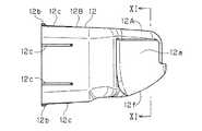
以下、本発明の第1の実施形態を図面に基づいて説明すると、図1に示される如く、車両用周辺視認装置は、内部に車両周辺を撮像するためのCCDカメラ等からなる撮像機器や該撮像機器に外部の景色を案内する光学系機器等を収容するケース11を備え、該ケース11は前述同様、フロントケース体12とリアケース体13とを備えた構造とされ、フロントケース体12とリアケース体13とはパッキン14を介して互いにネジ15締結により着脱自在に固定する構造とされている。
【0028】
そして、フロントケース体12の漸次先細状とされる前半部12A両側に、車両周辺の左右両側の景色を取り込むための光を透過する略矩形の透光窓部12aがそれぞれ構成されている。
【0029】
また、フロントケース体12の両透光窓部12a部分を残してフロントケース体12を覆うカバー体17が備えられており、このカバー体17はフロントケース体12を覆うだけでなく、図3に示される如く、フロントケース体12とリアケース体13との合わせ面(図17の合わせ面6参照)の周囲をも覆う構造とされている。なお、本実施形態においては、カバー体17に各透光窓部12a対応位置の下側を覆う部分を有していないが、上側と同様、下側も覆う構造であってもよい。
【0030】
さらに、フロントケース体12における後部側に位置した上面および下面の幅方向中間部には、係止突部12bがそれぞれ突設されており、カバー体17の対応する部分には、各係止突部12bが係脱自在に係止する被係止部としての係止孔17aがそれぞれ形成されている。
【0031】
また、図2にも示される如く、フロントケース体12の後半部12Bに対応するカバー体17の下部には、適宜大きさの水抜き孔17bが適宜数形成されている。
【0032】
前記フロントケース体12における後半部12Bの上面、下面および左右両側面に、それぞれ、カバー体17の嵌合方向に沿って僅かに突出する突条のガタ止めリブ12cが周方向に離隔して複数形成されている。
【0033】
さらに、図3および図4に示される如く、ケース11に対してカバー体17が装着された状態で、フロントケース体12の各透光窓部12aが、その周縁部でカバー体17より段差19を有して外方に突出するように構成されている。この段差19の外方への突出量Lは、例えば、0.2mm程度あればよい。
【0034】
また、フロントケース体12の先端部外面12dと、カバー体17の装着状態でその先端部外面12dに対向するカバー体17の先端部内面17cとが、両面接着テープ20を介して互いに接着する構造とされている。
【0035】
そして、フロントケース体12は、透明な樹脂、例えばポリカーボネイト樹脂で成形され、傷付き防止の観点から透明で硬質のコーティング剤、いわゆるハードコート剤、例えば、UV硬化アクリルが塗布されている。
【0036】
また、リアケース体13は遮光性を有する樹脂やアルミ材等により形成され、カバー体17はABS樹脂等で形成され、車両のボディーやグリル等の色に合わせた色塗装が施された構造とされている。
【0037】
そして、組付けに際しては、フロントケース体12とリアケース体13とをパッキン14を介してネジ15締結し、フロントケース体12の先端部外面12dに両面接着テープ20を貼り付けた状態で、フロントケース体12側からカバー体17をかぶせていき、押し込むことによって各係止突部12bを各係止孔17aに嵌合させれば、各係止突部12bと各係止孔17aとが互いに抜止状に係止されると共に、両面接着テープ20の他面にカバー体17の先端部内面17cが接着される。
【0038】
本実施形態は以上のように構成されており、従来、遮光のための色塗装が必要とされていた部分を別体のカバー体17としたことによって、フロントケース体12に対してはハードコート剤の塗布のみでよく、カバー体17に対しては色塗装のみでよいため、従来のようなマスキングが不要で、それぞれの塗布が単一工程となるため、従来のような歩留まり悪化も解消できる利点がある。
【0039】
また、フロントケース体12およびカバー体17に、それぞれハードコート剤および色塗料の単一種類を塗布するだけであるため、大きな温度変化の繰り返しによっても、塗料やハードコート剤の割れや剥がれが有効に防止できる。
【0040】
さらに、フロントケース体12とリアケース体13との合わせ面の周囲をカバー体17により覆っているため、車両の高圧洗浄時等においても、フロントケース体12とリアケース体13との合わせ面に直接高圧水が当たらず、合わせ面からの水の浸入が有効に防止でき、防水性能の向上が図れる。
【0041】
また、カバー体17の下部に水抜き孔17bが形成されているため、ケース11とカバー体17との相互間の隙間に水や油等の不要物が浸入しても不用意な溜まりが有効に防止できる。
【0042】
さらに、ケース11に対する装着が、係止突部12bと係止孔17aとの係止による構造であり、着脱作業がいわゆるワンタッチで簡単に行え、カバー体17の傷や割れによる損傷時の交換作業が容易に行えるという利点がある。
【0043】
また、フロントケース体12に複数のガタ止めリブ12cが形成されているため、カバー体17装着状態で、各ガタ止めリブ12cがカバー体17内周面に圧接され、カバー体17のガタツキ発生が有効に防止できる。この際、両面接着テープ20によってフロントケース体12の先端部外面12dとカバー体17の先端部内面17cとを互いに接着しておけば、カバー体17のガタツキがより一層効果的に防止でき、フロントケース体12によるカバー体17の保持力が向上する。
【0044】
さらに、各透光窓部12aは、その周縁部でカバー体17より段差19を有して外方に突出しているため、ゴミ・ホコリ・ワックス等を拭き取った際に、それらワックス等が段差19の入隅部分に溜まる構造となり、透光窓部12a表面側での残りが有効に防止できる利点もある。
【0045】
図5は第2の実施形態を示しており、カバー体17の先端部内面17cに嵌合凸部17dが設けられ、嵌合凸部17dと対向するフロントケース体12の先端部外面12dに嵌合凸部17dが嵌合される嵌合凹部12eが設けられた構造とされ、ケース11に対するカバー体17の装着状態で、嵌合凹部12eに嵌合凸部17dが嵌脱自在に嵌合する構造とされている。
【0046】
この場合においても、カバー体17のガタツキが効果的に防止でき、フロントケース体12によるカバー体17の保持力が向上する利点がある。
【0047】
図6ないし図13は第3の実施形態を示しており、前記第1の実施形態と同様構成部分は同一符号を付し、その説明を省略する。
【0048】
即ち、第1の実施形態においては、図1や図3に示されるように、フロントケース体12の前半部12Aにおける左右両側面にそれぞれ透光窓部12aが備えられており、これら両透光窓部12aの下面側をつなぐ部分も光を透過可能な構造とされ、いわゆる下面側の透光窓部12fを構成している。そして、左右両側面の両透光窓部12aは平面構造とされ、下面の透光窓部12fは円錐形状の一部の曲面から構成された構造とされている。
【0049】
これに対し、本実施形態においては、フロントケース体12の前半部12Aにおける左右両側面にそれぞれ備えられた両透光窓部12aの下面側をつなぐ透光窓部12fは、楕円をその長軸回りに回転させて得られる楕円面形状の一部の曲面から構成された構造とされており、その上端縁から両側の各透光窓部12aが上方に連続状に延設された構造とされている。即ち、両側面の各透光窓部12aと下面の透光窓部12fとがそれぞれ曲面で形成されると共に、両側面の各透光窓部12aの下端縁と下面の透光窓部12fの上端縁とが互いに連続する滑らかな曲面で連続状に接続された構造とされている。
【0050】
この際、図11ないし図13に示される如く、両透光窓部12aと透光窓部12fとの肉厚はそれぞれ均一な同じ肉厚に形成されている。
【0051】
そして、その他の構造は第1の実施形態と略同様に構成されている。即ち、フロントケース体12は、透明な樹脂、例えばポリカーボネイト樹脂で成形され、例えば、UV硬化アクリルが塗布されており、リアケース体13は遮光性を有する樹脂やアルミ材等により形成され、カバー体17はABS樹脂等で形成され、車両のボディーやグリル等の色に合わせた色塗装が施された構造とされている。そして、その組付け構造も同様に構成されている。
【0052】
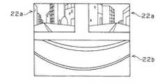
従って、本実施形態においても、第1の実施形態と同様の効果が得られる。そしてまた、第1の実施形態においては左右両側面の両透光窓部12aが平面で、下面の透光窓部12fが直線で形成される曲面であり、両側の両透光窓部12aと下側の透光窓部12fとの接続部分は平面と曲面とのつながりとなり、形状が異なる各透光窓部12a、12fを無理につなぐ構造となって、部分的なひずみにより、図14に示される如く、左右両側の透光窓部12aから取込まれた映像22aは何ら支障がないが、下面側の透光窓部12fから取込まれた映像22bに一部ゆがみが生じる欠点がある。
【0053】
これに対し、本実施形態においては、左右両側面の両透光窓部12aと下面の透光窓部12fとが共に曲面構造とされ、しかも均一な同じ肉厚で、かつ連続する滑らかな曲面で互いに接続されているため、両透光窓部12aと透光窓部12fとの接続部分での極端な境界部が生じず、図15に示される如く、左右両側の透光窓部12aから取込まれた映像22aだけでなく、下面側の透光窓部12fから取込まれた映像22bにもゆがみが生じず、ここに、車両下方の映像も良好に取込むことができ、製品における品質向上が図れる利点がある。
【0054】
なお、上記実施形態において、フロントケース体12の外周面にガタ止めリブ12cが設けられた構造を示しているが、カバー体17の内周面側にガタ止めリブが設けられる構造であってもよく、さらには双方にガタ止めリブ12cが設けられる構造であってもよい。
【0055】
また、カバー体17に係止突部12bが係止される貫通状の係止孔17aが形成された構造を示しているが、係止突部12bが嵌脱自在に嵌合されて係止される凹部であってもよい。
【0056】
さらには、フロントケース体12に設けられている係止突部12bをリアケース体側に設ける構造であってもよい。
【0057】
また、カバー体17に嵌合凸部17dを設け、フロントケース体12に嵌合凹部12eを設けた構造を示しているが、カバー体17に嵌合凹部を設け、フロントケース体12に嵌合凸部を設ける構造としてもよい。
【0058】
さらに、第3の実施形態において、下面の透光窓部12fが楕円面形状の曲面とされた構造を示しているが、両透光窓部12aと透光窓部12fとを互いに連続する曲面で接続する構造であれば、取込まれた映像におけるゆがみの発生が軽減でき、また、両透光窓部12aと透光窓部12fとを互いに連続する楕円面形状の曲面とすれば、取込まれた映像におけるゆがみの発生が一層有効に防止でき、さらには、両透光窓部12aと透光窓部12fとを互いに連続する球面形状の曲面とすれば、取込まれた映像におけるゆがみの発生がより一層有効に防止できる。
【0059】
【発明の効果】
以上のように本発明の車両用周辺視認装置によれば、ケースが、透光窓部を有するフロントケース体と、該フロントケース体に接合されて着脱自在に固定されるリアケース体とを備え、透光窓部を残してフロントケース体を覆うと共に、フロントケース体とリアケース体との合わせ面の周囲を覆うカバー体がさらに備えられた構造であり、従来遮光のための色塗装が必要とされていた部分を別体のカバー体としたことによって、フロントケース体に対してはハードコート剤の塗布のみでよく、カバー体に対しては色塗装のみでよいため、従来のようなマスキングが不要で、それぞれの塗布工程が単一となるため、従来のような歩留まり悪化も解消できる利点がある。
【0060】
また、フロントケース体およびカバー体に、それぞれハードコート剤および色塗料の単一種類を塗布するだけであるため、大きな温度変化の繰り返しによっても、塗料やハードコート剤の割れや剥がれが有効に防止できる利点もある。
【0061】
さらに、フロントケース体とリアケース体との合わせ面の周囲をカバー体により覆っているため、車両の高圧洗浄時等においても、フロントケース体とリアケース体との合わせ面に直接高圧水が当たらず、合わせ面からの水の浸入が有効に防止でき、防水性能の向上が図れる。
【0062】
また、フロントケース体の外周面もしくはカバー体の内周面の少なくともいずれか一方にガタ止めリブが設けられた構造とすれば、カバー体装着状態におけるカバー体17のガタツキ発生が有効に防止できる利点がある。
【0063】
さらに、ケースに係止突部が設けられ、カバー体に、ケースに対する装着状態で係止突部が係脱自在に係止する被係止部が設けられた構造とすれば、ケースに対するカバー体の装着が、係止突部と被係止部との係止による構造であり、着脱作業が簡単に行え、カバー体の傷や割れによる損傷時の交換作業が容易に行えるという利点がある。
【0064】
また、カバー体の下部に水抜き孔が形成された構造とすれば、ケースとカバー体との相互間の隙間に水や油等の不要物が浸入しても不用意な溜まりが有効に防止できるという利点がある。
【0065】
さらに、ケースに対するカバー体の装着状態で、フロントケース体の透光窓部が、その周縁部でカバー体より段差を有して外方に突出されている構造とすれば、透光窓部表面側でのワックス等の残りが有効に防止できる利点がある。
【0066】
また、ケースの先端部外面と、カバー体の装着状態でその先端部外面に対向するカバー体の先端部内面とのいずれか一方に嵌合凸部が設けられると共に、他方に嵌合凸部が嵌合される嵌合凹部が設けられた構造や、ケースの先端部外面と、カバー体の装着状態でその先端部外面に対向するカバー体の先端部内面とが、両面接着テープにより互いに接着された構造とすることによって、装着状態におけるカバー体のガタツキがより効果的に防止でき、フロントケース体によるカバー体の保持力が向上するという利点がある。
【0067】
さらに、透光窓部が、フロントケース体における左右両側面にそれぞれ備えられると共に、それら両側面の両透光窓部間の下面側にも透光窓部が備えられ、両側面の両透光窓部と下面の透光窓部とがそれぞれ曲面で形成されると共に、両側面の両透光窓部と下面の透光窓部とが互いに連続する曲面で接続され、かつ両側面の両透光窓部と下面の透光窓部とが同じ肉厚で形成されている構造とすれば、下面の透光窓部から取込まれた映像におけるゆがみの発生が軽減でき、車両下方の映像も良好に取込むことができ、製品における品質向上が図れるという利点がある。
【0068】
また、両側面および下面の各透光窓部が楕円面形状の曲面とされている構造とすれば、両側面および下面の各透光窓部から取込まれた映像におけるゆがみの発生がより有効に防止でき、さらに、両側面および下面の各透光窓部が球面形状の曲面とされている構造とすれば、両側面および下面の各透光窓部から取込まれた映像におけるゆがみの発生がより一層有効に防止できるという利点がある。
【図面の簡単な説明】
【図1】本発明の第1の実施形態にかかる車両用周辺視認装置の要部分解斜視図である。
【図2】同カバー体の底面図である。
【図3】同組付け状態の斜視図である。
【図4】同一部断面拡大図である。
【図5】第2の実施形態を示す要部断面拡大図である。
【図6】第3の実施形態を示す斜視図である。
【図7】同側面図である。
【図8】同正面図である。
【図9】同底面図である。
【図10】フロントケース体の側面図である。
【図11】図10におけるXI−XI線断面矢視図である。
【図12】フロントケース体の断面側面図である。
【図13】図12におけるXIII−XIII線断面矢視図である。
【図14】第1の実施形態により取込まれた映像の説明図である。
【図15】第3の実施形態により取込まれた映像の説明図である。
【図16】従来例を示す分解斜視図である。
【図17】同組付け状態の斜視図である。
【符号の説明】
11 ケース
12 フロントケース体
12a 透光窓部
12b 係止突部
12c ガタ止めリブ
12d 先端部外面
12e 嵌合凹部
12f 透光窓部
13 リアケース体
14 パッキン
17 カバー体
17a 係止孔
17b 水抜き孔
17c 先端部内面
17d 嵌合凸部
19 段差
20 両面接着テープ[0001]
BACKGROUND OF THE INVENTION
The present invention relates to a vehicle periphery visual recognition device that is mounted on a vehicle such as an automobile and images a blind spot of a driver around the vehicle.
[0002]
[Prior art]
When a car approaches an intersection, it is necessary to confirm the safety on the left and right. However, at intersections with poor visibility on the left and right and intersections where no signal is installed, the driver makes the vehicle slightly enter the intersection to make the left and right safe. It was necessary to confirm.
[0003]
Therefore, it is necessary to pay attention to the entry into the intersection, and after entering the vehicle, it is necessary to visually confirm both the left and right sides directly to confirm safety, which is a mental burden on the driver.
[0004]
Therefore, in order to reduce the burden, in recent years, an image pickup device having a CCD camera or the like is attached to the front grille or bumper upper portion of an automobile, and the left and right landscapes on both sides of the vehicle are captured by this image pickup device. A so-called vehicle periphery visual recognition device has been proposed that supports driving of a driver by displaying left and right images on both sides of a vehicle on a display means including an LCD (liquid crystal display) installed inside the vehicle (for example, , See
[0005]
In addition, according to the apparatus of
[0006]
[Patent Document 1]
Japanese Patent Laid-Open No. 2001-122020 [Patent Document 2]
Japanese Patent Laid-Open No. 2002-46531
[Problems to be solved by the invention]
According to the vehicle periphery visual recognition apparatus as described above, it is necessary to dispose an imaging device such as a CCD camera inside the case and an optical system device such as a reflecting mirror or a prism that guides an external scenery to the imaging means. Therefore, a case with a two-part structure is usually used.
[0008]
For example, as shown in FIGS. 16 and 17, the
[0009]
Further, in order to capture the left and right scenery, for example, transparent light transmitting window portions 2a for transmitting light are provided on both sides of the
[0010]
At this time, if the translucent window portion 2a is formed of a transparent material, and other portions of the
[0011]
Therefore, if the
[0012]
In this case, when the color of the
[0013]
In addition, it is necessary to apply a hard coat agent from the viewpoint of preventing damage to the
[0014]
Furthermore, since the thermal expansion coefficient differs between the color paint and the hard coat agent, the paint and the hard coat agent may be cracked or peeled off due to repeated large temperature changes.
[0015]
Further, when the
[0016]
Further, when high-pressure water directly hits the mating surface 6 between the
[0017]
Therefore, an object of the present invention is to provide a vehicle periphery visual recognition device that solves the above problems.
[0018]
[Means for Solving the Problems]
The technical means for solving the above-mentioned problem is mounted on a vehicle, images the periphery of the vehicle with an internal imaging device through a transparent window portion that transmits light provided in the case, and the captured information is input into the vehicle. In the vehicular peripheral viewing device provided, the case includes a front case body having the translucent window portion, and a rear case body that is joined to the front case body and is detachably fixed. And a cover body that covers the periphery of the mating surface of the front case body and the rear case body while further covering the front case body leaving a portion.
[0019]
Moreover, it is good also as a structure where the backlash rib was provided in at least any one of the outer peripheral surface of the said front case body, or the internal peripheral surface of the said cover body.
[0020]
Further, the case may have a structure in which a locking projection is provided on the case, and the cover body is provided with a locked portion in which the locking projection is detachably locked when mounted on the case.
[0021]
Moreover, it is good also as a structure in which the drain hole was formed in the lower part of the said cover body.
[0022]
Furthermore, it is good also as a structure where the said translucent window part of the said front case body has a level | step difference from the cover body in the mounting state of the said cover body with respect to the said case, and protrudes outward.
[0023]
In addition, a fitting convex portion is provided on one of the outer surface of the front end portion of the case and the inner surface of the front end portion of the cover body facing the outer surface of the front end portion when the cover body is mounted, and the fitting is provided on the other side. It is good also as a structure in which the fitting recessed part in which a fitting convex part is fitted is provided.
[0024]
Further, the outer surface of the distal end portion of the case and the inner surface of the distal end portion of the cover body facing the outer surface of the distal end portion when the cover body is mounted may be bonded to each other with a double-sided adhesive tape.
[0025]
Further, the translucent window part is provided on each of the left and right side surfaces of the front case body, and the translucent window part is also provided on the lower surface side between the translucent window parts on both side surfaces. The translucent window portion and the translucent window portion on the lower surface are each formed with a curved surface, the translucent window portions on both sides and the translucent window portion on the lower surface are connected with a curved surface that is continuous with each other, and It is good also as a structure where both the translucent window part and the translucent window part of a lower surface are formed with the same thickness.
[0026]
Furthermore, it is good also as a structure which makes each translucent window part of the said both sides | surfaces and the said lower surface into an elliptical curved surface or a spherical curved surface.
[0027]
DETAILED DESCRIPTION OF THE INVENTION
Hereinafter, a first embodiment of the present invention will be described with reference to the drawings. As shown in FIG. 1, a vehicle periphery visual recognition device includes an imaging device including a CCD camera or the like for imaging the periphery of a vehicle, and the like. The imaging device includes a
[0028]
Further, on both sides of the
[0029]
Further, a
[0030]
Further, locking
[0031]
In addition, as shown in FIG. 2, an appropriate number of
[0032]
[0033]
Further, as shown in FIG. 3 and FIG. 4, in a state where the
[0034]
Further, a structure in which a front end portion
[0035]
And the
[0036]
The
[0037]
When assembling, the
[0038]
The present embodiment is configured as described above. Conventionally, a hard coat is applied to the
[0039]
Further, since only a single type of hard coat agent and color paint is applied to the
[0040]
Further, since the periphery of the mating surface of the
[0041]
Moreover, since the
[0042]
Furthermore, the attachment to the
[0043]
In addition, since the
[0044]
Furthermore, each
[0045]
FIG. 5 shows a second embodiment in which a fitting
[0046]
Even in this case, it is possible to effectively prevent the
[0047]
6 to 13 show a third embodiment, and the same components as those in the first embodiment are denoted by the same reference numerals, and the description thereof is omitted.
[0048]
That is, in the first embodiment, as shown in FIGS. 1 and 3, the left and right side surfaces of the
[0049]
On the other hand, in the present embodiment, the
[0050]
At this time, as shown in FIGS. 11 to 13, the thicknesses of both the light-transmitting
[0051]
The other structures are configured in substantially the same manner as in the first embodiment. That is, the
[0052]
Therefore, also in this embodiment, the same effect as that of the first embodiment can be obtained. Further, in the first embodiment, both the light-transmitting
[0053]
On the other hand, in this embodiment, both the
[0054]
In addition, in the said embodiment, although the structure where the rattling
[0055]
In addition, the
[0056]
Furthermore, the structure which provides the latching
[0057]
Further, although the
[0058]
Furthermore, in the third embodiment, a structure in which the
[0059]
【The invention's effect】
As described above, according to the vehicle peripheral vision device of the present invention, the case includes the front case body having the transparent window portion, and the rear case body that is joined to the front case body and is detachably fixed. In addition to covering the front case body with the light-transmitting window part and covering the periphery of the mating surface of the front case body and the rear case body, it is equipped with a conventional color coating for shading By using the cover part as a separate cover body, it is only necessary to apply a hard coat agent to the front case body, and only the color coating to the cover body. Is unnecessary, and each coating process is single, so that there is an advantage that it is possible to eliminate the deterioration in yield as in the prior art.
[0060]
In addition, since only a single type of hard coat agent and color paint is applied to the front case body and cover body, cracks and peeling of the paint and hard coat agent can be effectively prevented even by repeated large temperature changes. There is also an advantage that can be done.
[0061]
Furthermore, since the periphery of the mating surface of the front case body and the rear case body is covered with a cover body, even when high-pressure water is directly applied to the mating surface of the front case body and the rear case body, even during high-pressure cleaning of the vehicle, etc. In addition, water can be effectively prevented from entering from the mating surfaces, and waterproof performance can be improved.
[0062]
Further, if the structure is provided with the backlash rib on at least one of the outer peripheral surface of the front case body and the inner peripheral surface of the cover body, it is possible to effectively prevent the
[0063]
Furthermore, if the case is provided with a locking projection, and the cover body is provided with a locked portion in which the locking projection is releasably locked when mounted on the case, the cover body with respect to the case The mounting is a structure by locking the locking protrusion and the locked portion, and there is an advantage that the attaching / detaching operation can be easily performed and the replacing operation can be easily performed when the cover body is damaged or cracked.
[0064]
In addition, if a structure with a drain hole is formed in the lower part of the cover body, it is possible to effectively prevent inadvertent accumulation even if unnecessary materials such as water and oil enter the gap between the case and the cover body. There is an advantage that you can.
[0065]
Further, when the cover body is attached to the case, the translucent window portion of the front case body has a step projecting outward from the cover body at the peripheral edge thereof. There is an advantage that the remainder such as wax on the side can be effectively prevented.
[0066]
In addition, a fitting convex portion is provided on one of the outer surface of the front end portion of the case and the inner surface of the front end portion of the cover body facing the outer surface of the front end portion when the cover body is mounted, and the fitting convex portion is provided on the other side. The structure provided with a fitting recess to be fitted, the outer surface of the tip of the case, and the inner surface of the tip of the cover that faces the outer surface of the tip when the cover is mounted are bonded to each other with a double-sided adhesive tape. By adopting the structure, it is possible to more effectively prevent the cover body from rattling in the mounted state, and there is an advantage that the holding force of the cover body by the front case body is improved.
[0067]
Furthermore, a translucent window portion is provided on each of the left and right side surfaces of the front case body, and a translucent window portion is also provided on the lower surface side between the both translucent window portions on both side surfaces. The window portion and the light transmitting window portion on the lower surface are each formed with a curved surface, the light transmitting window portions on both side surfaces and the light transmitting window portion on the lower surface are connected to each other with curved surfaces that are continuous with each other, and If the light window part and the light-transmitting window part on the bottom surface are formed with the same thickness, the occurrence of distortion in the image captured from the light-transmitting window part on the bottom surface can be reduced. There is an advantage that it can be taken in well and the quality of the product can be improved.
[0068]
In addition, if the translucent windows on both sides and the bottom are made into an elliptical curved surface, distortion is more effective in images captured from the translucent windows on both sides and the bottom. Furthermore, if each of the translucent window portions on both side surfaces and the lower surface has a spherical curved surface, distortion will occur in the images captured from the translucent window portions on both side surfaces and the lower surface. There is an advantage that can be more effectively prevented.
[Brief description of the drawings]
FIG. 1 is an exploded perspective view of a main part of a vehicle peripheral vision device according to a first embodiment of the present invention.
FIG. 2 is a bottom view of the cover body.
FIG. 3 is a perspective view of the assembled state.
FIG. 4 is an enlarged sectional view of the same part.
FIG. 5 is an enlarged cross-sectional view of a main part showing a second embodiment.
FIG. 6 is a perspective view showing a third embodiment.
FIG. 7 is a side view of the same.
FIG. 8 is a front view of the same.
FIG. 9 is a bottom view of the same.
FIG. 10 is a side view of the front case body.
11 is a cross-sectional view taken along the line XI-XI in FIG.
FIG. 12 is a cross-sectional side view of the front case body.
13 is a cross-sectional view taken along line XIII-XIII in FIG.
FIG. 14 is an explanatory diagram of an image captured by the first embodiment.
FIG. 15 is an explanatory diagram of an image captured by the third embodiment.
FIG. 16 is an exploded perspective view showing a conventional example.
FIG. 17 is a perspective view of the assembled state.
[Explanation of symbols]
DESCRIPTION OF
Claims (10)
Translated fromJapanese前記ケースが、前記透光窓部を有するフロントケース体と、該フロントケース体に接合されて着脱自在に固定されるリアケース体とを備え、
前記透光窓部を残して前記フロントケース体を覆うと共に、フロントケース体とリアケース体との合わせ面の周囲を覆うカバー体がさらに備えられたことを特徴とする車両用周辺視認装置。In a vehicle peripheral vision device that is mounted on a vehicle and images the periphery of the vehicle with an internal imaging device through a transparent window that transmits light provided in the case, and provides the captured information in the vehicle,
The case includes a front case body having the translucent window portion, and a rear case body that is joined to the front case body and is detachably fixed.
A vehicle periphery visual recognition device, further comprising a cover body that covers the front case body while leaving the translucent window portion and covers a periphery of a mating surface of the front case body and the rear case body.
Priority Applications (3)
| Application Number | Priority Date | Filing Date | Title |
|---|---|---|---|
| JP2003112466AJP4191527B2 (en) | 2002-12-11 | 2003-04-17 | Peripheral visual recognition device for vehicles |
| US10/730,912US7304661B2 (en) | 2002-12-11 | 2003-12-10 | Vehicle periphery monitoring apparatus |
| DE10357781ADE10357781B4 (en) | 2002-12-11 | 2003-12-10 | Device for monitoring the environment of a vehicle |
Applications Claiming Priority (2)
| Application Number | Priority Date | Filing Date | Title |
|---|---|---|---|
| JP2002359158 | 2002-12-11 | ||
| JP2003112466AJP4191527B2 (en) | 2002-12-11 | 2003-04-17 | Peripheral visual recognition device for vehicles |
Publications (2)
| Publication Number | Publication Date |
|---|---|
| JP2004237968A JP2004237968A (en) | 2004-08-26 |
| JP4191527B2true JP4191527B2 (en) | 2008-12-03 |
Family
ID=32396317
Family Applications (1)
| Application Number | Title | Priority Date | Filing Date |
|---|---|---|---|
| JP2003112466AExpired - Fee RelatedJP4191527B2 (en) | 2002-12-11 | 2003-04-17 | Peripheral visual recognition device for vehicles |
Country Status (3)
| Country | Link |
|---|---|
| US (1) | US7304661B2 (en) |
| JP (1) | JP4191527B2 (en) |
| DE (1) | DE10357781B4 (en) |
Families Citing this family (82)
| Publication number | Priority date | Publication date | Assignee | Title |
|---|---|---|---|---|
| US5877897A (en) | 1993-02-26 | 1999-03-02 | Donnelly Corporation | Automatic rearview mirror, vehicle lighting control and vehicle interior monitoring system using a photosensor array |
| US5910854A (en) | 1993-02-26 | 1999-06-08 | Donnelly Corporation | Electrochromic polymeric solid films, manufacturing electrochromic devices using such solid films, and processes for making such solid films and devices |
| US6822563B2 (en) | 1997-09-22 | 2004-11-23 | Donnelly Corporation | Vehicle imaging system with accessory control |
| US5668663A (en) | 1994-05-05 | 1997-09-16 | Donnelly Corporation | Electrochromic mirrors and devices |
| US6891563B2 (en) | 1996-05-22 | 2005-05-10 | Donnelly Corporation | Vehicular vision system |
| US7655894B2 (en) | 1996-03-25 | 2010-02-02 | Donnelly Corporation | Vehicular image sensing system |
| US8294975B2 (en) | 1997-08-25 | 2012-10-23 | Donnelly Corporation | Automotive rearview mirror assembly |
| US6172613B1 (en) | 1998-02-18 | 2001-01-09 | Donnelly Corporation | Rearview mirror assembly incorporating vehicle information display |
| US6326613B1 (en) | 1998-01-07 | 2001-12-04 | Donnelly Corporation | Vehicle interior mirror assembly adapted for containing a rain sensor |
| US6124886A (en) | 1997-08-25 | 2000-09-26 | Donnelly Corporation | Modular rearview mirror assembly |
| US6445287B1 (en) | 2000-02-28 | 2002-09-03 | Donnelly Corporation | Tire inflation assistance monitoring system |
| US8288711B2 (en) | 1998-01-07 | 2012-10-16 | Donnelly Corporation | Interior rearview mirror system with forwardly-viewing camera and a control |
| US6693517B2 (en) | 2000-04-21 | 2004-02-17 | Donnelly Corporation | Vehicle mirror assembly communicating wirelessly with vehicle accessories and occupants |
| US6477464B2 (en) | 2000-03-09 | 2002-11-05 | Donnelly Corporation | Complete mirror-based global-positioning system (GPS) navigation solution |
| US6329925B1 (en) | 1999-11-24 | 2001-12-11 | Donnelly Corporation | Rearview mirror assembly with added feature modular display |
| AU2001243285A1 (en) | 2000-03-02 | 2001-09-12 | Donnelly Corporation | Video mirror systems incorporating an accessory module |
| US7370983B2 (en) | 2000-03-02 | 2008-05-13 | Donnelly Corporation | Interior mirror assembly with display |
| US7167796B2 (en) | 2000-03-09 | 2007-01-23 | Donnelly Corporation | Vehicle navigation system for use with a telematics system |
| AU2002251807A1 (en) | 2001-01-23 | 2002-08-19 | Donnelly Corporation | Improved vehicular lighting system for a mirror assembly |
| US7581859B2 (en) | 2005-09-14 | 2009-09-01 | Donnelly Corp. | Display device for exterior rearview mirror |
| US7255451B2 (en) | 2002-09-20 | 2007-08-14 | Donnelly Corporation | Electro-optic mirror cell |
| ES2391556T3 (en) | 2002-05-03 | 2012-11-27 | Donnelly Corporation | Object detection system for vehicles |
| US6918674B2 (en) | 2002-05-03 | 2005-07-19 | Donnelly Corporation | Vehicle rearview mirror system |
| US7329013B2 (en) | 2002-06-06 | 2008-02-12 | Donnelly Corporation | Interior rearview mirror system with compass |
| AU2003237424A1 (en) | 2002-06-06 | 2003-12-22 | Donnelly Corporation | Interior rearview mirror system with compass |
| WO2004026633A2 (en) | 2002-09-20 | 2004-04-01 | Donnelly Corporation | Mirror reflective element assembly |
| US7310177B2 (en) | 2002-09-20 | 2007-12-18 | Donnelly Corporation | Electro-optic reflective element assembly |
| US7446924B2 (en) | 2003-10-02 | 2008-11-04 | Donnelly Corporation | Mirror reflective element assembly including electronic component |
| US7308341B2 (en) | 2003-10-14 | 2007-12-11 | Donnelly Corporation | Vehicle communication system |
| US7526103B2 (en) | 2004-04-15 | 2009-04-28 | Donnelly Corporation | Imaging system for vehicle |
| US7881496B2 (en) | 2004-09-30 | 2011-02-01 | Donnelly Corporation | Vision system for vehicle |
| EP1883855B1 (en) | 2005-05-16 | 2011-07-20 | Donnelly Corporation | Vehicle mirror assembly with indicia at reflective element |
| JP2007062670A (en)* | 2005-09-02 | 2007-03-15 | Auto Network Gijutsu Kenkyusho:Kk | Waterproof case and camera device for in-vehicle camera |
| EP1949666B1 (en) | 2005-11-01 | 2013-07-17 | Magna Mirrors of America, Inc. | Interior rearview mirror with display |
| CN101401024B (en) | 2006-03-09 | 2016-03-16 | 金泰克斯公司 | Comprise the vehicle rearview assembly of high intensity display |
| DE102006029892B4 (en)* | 2006-06-28 | 2018-10-18 | Bayerische Motoren Werke Aktiengesellschaft | Camera system for a motor vehicle |
| WO2008024639A2 (en) | 2006-08-11 | 2008-02-28 | Donnelly Corporation | Automatic headlamp control system |
| US8154418B2 (en) | 2008-03-31 | 2012-04-10 | Magna Mirrors Of America, Inc. | Interior rearview mirror system |
| US9487144B2 (en) | 2008-10-16 | 2016-11-08 | Magna Mirrors Of America, Inc. | Interior mirror assembly with display |
| JP5691188B2 (en)* | 2010-02-12 | 2015-04-01 | ソニー株式会社 | Camera device |
| KR101318543B1 (en)* | 2011-07-26 | 2013-10-16 | 엘지이노텍 주식회사 | Cable connect structure for camera module |
| ES2670031T3 (en)* | 2012-02-02 | 2018-05-29 | Illinois Tool Works Inc. | Assembly for fixing a vehicle camera |
| US10457209B2 (en) | 2012-02-22 | 2019-10-29 | Magna Electronics Inc. | Vehicle vision system with multi-paned view |
| US9319637B2 (en) | 2012-03-27 | 2016-04-19 | Magna Electronics Inc. | Vehicle vision system with lens pollution detection |
| US8879139B2 (en) | 2012-04-24 | 2014-11-04 | Gentex Corporation | Display mirror assembly |
| DE102012107170A1 (en)* | 2012-08-03 | 2014-05-15 | Kst Gmbh Kamera & System Technik | Camera outer housing for use in traffic engineering |
| US9707896B2 (en) | 2012-10-15 | 2017-07-18 | Magna Electronics Inc. | Vehicle camera lens dirt protection via air flow |
| US9445057B2 (en) | 2013-02-20 | 2016-09-13 | Magna Electronics Inc. | Vehicle vision system with dirt detection |
| KR101881346B1 (en) | 2013-03-15 | 2018-07-24 | 젠텍스 코포레이션 | Display mirror assembly |
| DE102013103930A1 (en)* | 2013-04-18 | 2014-10-23 | Huf Hülsbeck & Fürst Gmbh & Co. Kg | Device with a camera unit and a double-walled housing |
| JP2016534915A (en) | 2013-09-24 | 2016-11-10 | ジェンテックス コーポレイション | Display mirror assembly |
| US9511715B2 (en) | 2014-01-31 | 2016-12-06 | Gentex Corporation | Backlighting assembly for display for reducing cross-hatching |
| US10705332B2 (en) | 2014-03-21 | 2020-07-07 | Gentex Corporation | Tri-modal display mirror assembly |
| KR101894262B1 (en) | 2014-04-01 | 2018-09-04 | 젠텍스 코포레이션 | Automatic display mirror assembly |
| US9694751B2 (en) | 2014-09-19 | 2017-07-04 | Gentex Corporation | Rearview assembly |
| WO2016073848A1 (en) | 2014-11-07 | 2016-05-12 | Gentex Corporation | Full display mirror actuator |
| US10071689B2 (en) | 2014-11-13 | 2018-09-11 | Gentex Corporation | Rearview mirror system with a display |
| US10131279B2 (en) | 2014-12-03 | 2018-11-20 | Gentex Corporation | Display mirror assembly with an RF shield bezel |
| USD746744S1 (en) | 2014-12-05 | 2016-01-05 | Gentex Corporation | Rearview device |
| US9744907B2 (en) | 2014-12-29 | 2017-08-29 | Gentex Corporation | Vehicle vision system having adjustable displayed field of view |
| US9720278B2 (en) | 2015-01-22 | 2017-08-01 | Gentex Corporation | Low cost optical film stack |
| JP2018513810A (en) | 2015-04-20 | 2018-05-31 | ジェンテックス コーポレイション | Rear view assembly with decoration |
| EP3297870B1 (en) | 2015-05-18 | 2020-02-05 | Gentex Corporation | Full display rearview device |
| WO2016209877A1 (en) | 2015-06-22 | 2016-12-29 | Gentex Corporation | System and method for processing streamed video images to correct for flicker of amplitude-modulated lights |
| DE102015115363B4 (en)* | 2015-09-11 | 2023-12-28 | Connaught Electronics Ltd. | Camera with a camera housing, arrangement and motor vehicle |
| USD797627S1 (en) | 2015-10-30 | 2017-09-19 | Gentex Corporation | Rearview mirror device |
| USD798207S1 (en) | 2015-10-30 | 2017-09-26 | Gentex Corporation | Rearview mirror assembly |
| WO2017075420A1 (en) | 2015-10-30 | 2017-05-04 | Gentex Corporation | Toggle paddle |
| CN108349436B (en) | 2015-10-30 | 2019-12-20 | 金泰克斯公司 | Rear-view device |
| USD800618S1 (en) | 2015-11-02 | 2017-10-24 | Gentex Corporation | Toggle paddle for a rear view device |
| USD845851S1 (en) | 2016-03-31 | 2019-04-16 | Gentex Corporation | Rearview device |
| USD817238S1 (en) | 2016-04-29 | 2018-05-08 | Gentex Corporation | Rearview device |
| US10025138B2 (en) | 2016-06-06 | 2018-07-17 | Gentex Corporation | Illuminating display with light gathering structure |
| USD809984S1 (en) | 2016-12-07 | 2018-02-13 | Gentex Corporation | Rearview assembly |
| USD854473S1 (en) | 2016-12-16 | 2019-07-23 | Gentex Corporation | Rearview assembly |
| KR20190104990A (en) | 2016-12-30 | 2019-09-11 | 젠텍스 코포레이션 | Full display mirror with instant custom spotter view |
| EP3595931A4 (en) | 2017-03-17 | 2020-01-22 | Gentex Corporation | REVIEW REVERSE CAMERA WITH TWO |
| KR102073087B1 (en)* | 2018-10-04 | 2020-02-04 | 주식회사 세코닉스 | Camera module |
| RU2769852C1 (en)* | 2019-01-10 | 2022-04-07 | Мураками Корпорейшн | Vehicle lighting device |
| US11994272B2 (en) | 2021-08-20 | 2024-05-28 | Gentex Corporation | Lighting assembly and illumination system having a lighting assembly |
| DE102022105241B4 (en) | 2022-03-07 | 2025-01-02 | Knorr-Bremse Systeme für Nutzfahrzeuge GmbH | Camera mount for attachment to a vehicle body |
| DE102022105242A1 (en) | 2022-03-07 | 2023-09-07 | Knorr-Bremse Systeme für Nutzfahrzeuge GmbH | Camera mount for attachment to a vehicle body |
Family Cites Families (6)
| Publication number | Priority date | Publication date | Assignee | Title |
|---|---|---|---|---|
| JP2001122020A (en)* | 1999-10-29 | 2001-05-08 | Sumitomo Electric Ind Ltd | Left and right viewing devices for vehicles and their covers |
| JP2002019535A (en)* | 2000-07-07 | 2002-01-23 | Auto Network Gijutsu Kenkyusho:Kk | Mounting device for in-vehicle imaging machine |
| JP4245111B2 (en)* | 2000-07-31 | 2009-03-25 | 株式会社オートネットワーク技術研究所 | An exterior cover structure for a vehicle and a method for attaching the exterior cover structure for a vehicle. |
| KR100370217B1 (en)* | 2000-08-25 | 2003-01-29 | 삼성전자 주식회사 | CRT coupling apparatus of projection television |
| JP2002134184A (en)* | 2000-10-25 | 2002-05-10 | Yazaki Corp | Auxiliary equipment module |
| JP2002331869A (en)* | 2001-05-11 | 2002-11-19 | Auto Network Gijutsu Kenkyusho:Kk | Perimeter recognition device for vehicles |
- 2003
- 2003-04-17JPJP2003112466Apatent/JP4191527B2/ennot_activeExpired - Fee Related
- 2003-12-10USUS10/730,912patent/US7304661B2/ennot_activeExpired - Fee Related
- 2003-12-10DEDE10357781Apatent/DE10357781B4/ennot_activeExpired - Fee Related
Also Published As
| Publication number | Publication date |
|---|---|
| US7304661B2 (en) | 2007-12-04 |
| DE10357781A1 (en) | 2004-06-24 |
| US20040114039A1 (en) | 2004-06-17 |
| DE10357781B4 (en) | 2007-08-09 |
| JP2004237968A (en) | 2004-08-26 |
Similar Documents
| Publication | Publication Date | Title |
|---|---|---|
| JP4191527B2 (en) | Peripheral visual recognition device for vehicles | |
| CN108696676B (en) | camera module | |
| JP6399379B2 (en) | Digital video recorder | |
| US7660057B2 (en) | Lens assembly and imaging apparatus | |
| JP2003267129A (en) | Mirror for vehicle with built-in monitoring device | |
| JPH07267002A (en) | Monitor television built-in back mirror | |
| US20220295036A1 (en) | Vehicle body structure having camera | |
| US7791828B2 (en) | Lens assembly and imaging apparatus | |
| US12270912B2 (en) | Structure for mounting near infrared sensor and sensor cover to vehicle | |
| CA2171987C (en) | Multi-direction camera | |
| JP4335228B2 (en) | Built-in camera rearview mirror | |
| CN222145349U (en) | Surface glass of rearview mirror, vehicle fluid medium internal rearview mirror and vehicle | |
| CN112799199A (en) | lens | |
| CN110861582B (en) | Vehicle image pickup unit | |
| JP2005014858A (en) | Camera built-in door mirror | |
| JP3125772U (en) | Imaging lens for the rear surveillance camera of an automobile | |
| JP2004216958A (en) | Rear monitor camera for vehicle | |
| CN219601123U (en) | Mounting bracket and car of on-vehicle camera | |
| CN221775766U (en) | A vehicle | |
| CN216783426U (en) | Interior trim panel assembly, interior trim panel assembly and vehicle | |
| CN108528354B (en) | Vehicle-mounted camera bracket and automobile comprising same | |
| EP4603335A1 (en) | Inner mirror structure with built-in camera | |
| JP7692033B2 (en) | Vehicle information acquisition device cover | |
| JP4245111B2 (en) | An exterior cover structure for a vehicle and a method for attaching the exterior cover structure for a vehicle. | |
| US12304311B2 (en) | Display assembly for vehicle |
Legal Events
| Date | Code | Title | Description |
|---|---|---|---|
| A621 | Written request for application examination | Free format text:JAPANESE INTERMEDIATE CODE: A621 Effective date:20051202 | |
| TRDD | Decision of grant or rejection written | ||
| A01 | Written decision to grant a patent or to grant a registration (utility model) | Free format text:JAPANESE INTERMEDIATE CODE: A01 Effective date:20080916 | |
| A01 | Written decision to grant a patent or to grant a registration (utility model) | Free format text:JAPANESE INTERMEDIATE CODE: A01 | |
| A61 | First payment of annual fees (during grant procedure) | Free format text:JAPANESE INTERMEDIATE CODE: A61 Effective date:20080918 | |
| FPAY | Renewal fee payment (event date is renewal date of database) | Free format text:PAYMENT UNTIL: 20110926 Year of fee payment:3 | |
| R150 | Certificate of patent or registration of utility model | Free format text:JAPANESE INTERMEDIATE CODE: R150 | |
| FPAY | Renewal fee payment (event date is renewal date of database) | Free format text:PAYMENT UNTIL: 20120926 Year of fee payment:4 | |
| FPAY | Renewal fee payment (event date is renewal date of database) | Free format text:PAYMENT UNTIL: 20120926 Year of fee payment:4 | |
| FPAY | Renewal fee payment (event date is renewal date of database) | Free format text:PAYMENT UNTIL: 20130926 Year of fee payment:5 | |
| R250 | Receipt of annual fees | Free format text:JAPANESE INTERMEDIATE CODE: R250 | |
| LAPS | Cancellation because of no payment of annual fees |