JP4190765B2 - Security level information providing method and system - Google Patents
Security level information providing method and systemDownload PDFInfo
- Publication number
- JP4190765B2 JP4190765B2JP2002010888AJP2002010888AJP4190765B2JP 4190765 B2JP4190765 B2JP 4190765B2JP 2002010888 AJP2002010888 AJP 2002010888AJP 2002010888 AJP2002010888 AJP 2002010888AJP 4190765 B2JP4190765 B2JP 4190765B2
- Authority
- JP
- Japan
- Prior art keywords
- security level
- information
- vulnerability
- security
- level value
- Prior art date
- Legal status (The legal status is an assumption and is not a legal conclusion. Google has not performed a legal analysis and makes no representation as to the accuracy of the status listed.)
- Expired - Fee Related
Links
Images


Classifications
- G—PHYSICS
- G06—COMPUTING OR CALCULATING; COUNTING
- G06F—ELECTRIC DIGITAL DATA PROCESSING
- G06F21/00—Security arrangements for protecting computers, components thereof, programs or data against unauthorised activity
- G06F21/50—Monitoring users, programs or devices to maintain the integrity of platforms, e.g. of processors, firmware or operating systems
- G06F21/57—Certifying or maintaining trusted computer platforms, e.g. secure boots or power-downs, version controls, system software checks, secure updates or assessing vulnerabilities
- G06F21/577—Assessing vulnerabilities and evaluating computer system security
Landscapes
- Engineering & Computer Science (AREA)
- Computer Hardware Design (AREA)
- Computer Security & Cryptography (AREA)
- General Engineering & Computer Science (AREA)
- Software Systems (AREA)
- Theoretical Computer Science (AREA)
- Computing Systems (AREA)
- Physics & Mathematics (AREA)
- General Physics & Mathematics (AREA)
- Management, Administration, Business Operations System, And Electronic Commerce (AREA)
- Computer And Data Communications (AREA)
- Storage Device Security (AREA)
Description
Translated fromJapanese【0001】
【発明の属する技術分野】
この発明は、例えば、ネットワークに接続されたコンピュータシステム群のセキュリティレベルをリアルタイムで正確に評価し提供することができる方法及びシステムに関する。
【0002】
【従来の技術】
最近、クラッカー等により企業や官公庁のネットワークやサーバが攻撃されたり、新種ウィルスに感染するという被害が多発している。このことにより、ネットワークセキュリティの強化に注目が集まっている。ネットワークセキュリティを強化するには、ネットワーク及びこのネットワークに接続された自社機器のセキュリティレベルを絶えず正確に把握しておく必要がある。
【0003】
セキュリティレベルを評価するパラメータとしては、ネットワークやコンピュータのハードウエア及びソフトウエア的な構成といった静的な要素と、日々発生する脆弱点情報に応じて発生しそれに対応することによって変動する動的な要素とがある。企業活動にITを利用する企業にとっては、この動的な要素に迅速に対応しなければ経営リスクが無限大に拡大することになるため、経営者にとってもその管理が非常に重要な課題となっている。
【0004】
【発明が解決しようとする課題】
しかしながら、従来、このセキュリティレベルの把握はシステム管理者に任されており、経営者は、このシステム管理者からの報告を信じるしかなかった。一方、システム管理者の業務怠慢によりセキュリティレベルが低下等する場合もあり、このような要因を含めたセキュリティレベルの管理は非常に困難であった。
【0005】
一方、経営者自身が、膨大なセキュリティ情報から自己のシステムに必要な情報を見つけ出して把握し、しかもその対策をタイムラグ無く施すことは専門技術的に過ぎるため極めて困難である。
【0006】
この発明は、このような事情に鑑みてなされたものであり、経営者等、セキュリティに関して十分な知識を有さない者であっても理解できるようなセキュリティ情報を、システム管理者の採った作業を反映して、迅速に提供できるシステム及び方法を提供することを目的とする。
【0007】
【課題を解決するための手段】
上記課題を解決するため、この発明の第1の主要な観点によれば、コンピュータシステムによって特定の機器のセキュリティレベル情報を提供する方法であって、このコンピュータシステムは、前記特定の機器の環境情報を格納する環境情報格納部と、脆弱点の脅威に関して重み付けをするための脅威レベル値を含む脆弱点情報を格納する脆弱点情報格納部とを備え、この方法は、(a)コンピュータシステムの脆弱点情報提供部が、前記環境情報格納部に格納された特定の機器の環境情報に基づいて、前記脆弱点情報格納部からこの機器について前記脅威レベル値を含む脆弱点を特定し、この脆弱点の情報を前記機器に関連付ける工程と、(b)コンピュータシステムのセキュリティレベル算出部が、特定の機器について、この機器の種別、この機器について未だ対策を採っていない脆弱点の脅威レベル値、及び未対応の日数から、当該機器の当該脆弱点に関するセキュリティレベル値を算出する工程と、(c)コンピュータシステムのセキュリティレベル情報生成部が、前記(b)工程で求めたセキュリティレベル値に基づいて、この機器のセキュリティレベル情報を生成して出力する工程とを備えたことを特徴とするセキュリティレベル情報提供方法が提供される。
【0008】
このような構成によれば、未対応の脆弱点情報が存在する場合、機器の種別、その脆弱点の脅威レベル及び未対応の日数に基づいてセキュリティレベル値を算出し、それに基づいてセキュリティレベル情報を生成することができる。
【0009】
また、この方法は、さらに、(d)コンピュータシステムのセキュリティレベル比較部が、当該機器に関連付けられた未対応の脆弱点が複数ある場合、各脆弱点に関するセキュリティレベル値を比較し、各脆弱点のセキュリティレベル値のうち最も脅威度の高いセキュリティレベル値を当該機器のセキュリティレベル値として算出する工程を有し、前記(c)工程は、当該機器のセキュリティレベル値に基づいてセキュリティレベル情報を出力するものであることが好ましい。
【0010】
このような構成によれば、特定の機器に関連付けられた脆弱点情報が複数ある場合、そのうちもっとも脅威度の高い脆弱点情報に基づくセキュリティ値を当該機器のセキュリティ値とすることができる。
【0011】
この場合、さらに、(e)コンピュータシステムのセキュリティレベル比較部が、ネットワークに接続された機器が複数ある場合、各機器に関するセキュリティレベル値を比較し、各機器のセキュリティレベル値のうち最も脅威度の高いセキュリティレベル値を当該ネットワークのセキュリティレベル値として算出する工程を有し、前記(c)工程は、当該ネットワークのセキュリティレベル値に基づいてセキュリティレベル情報を出力するものであることが望ましい。
【0012】
このような構成によれば、複数の機器がネットワークに接続されている場合、上述のようにして求めた各機器のセキュリティ値に基づいて、ネットワーク全体のセキュリティ値を算出することができる。
【0013】
さらに、この発明の1の実施形態によれば、前記(c)工程は、(b)工程で求めたセキュリティレベル値と、機器やネットワークの基本構成等に基づいて算出した基本セキュリティ情報とに基づいてセキュリティレベル情報を出力するものである。
【0014】
更なる別の1の実施形態によれば、前記(c)工程は、セキュリティレベル情報生成部が、特定の機器若しくはこの機器が接続されたネットワークのセキュリティ基準値との比較で前記セキュリティレベル値を表現する工程を含むものである。
【0015】
このような構成によれば、当該システム若しくはネットワークが満たすべきセキュリティ値の基準値を定めておき、これとの比較で現在のセキュリティ値を表わすことができる。このことで、自社のセキュリティレベルの基準値を明確に把握していない経営者であっても、現在のセキュリティレベルが基準値との関係で相対的に表されるから容易に理解することができる。
【0016】
また、この発明の第2の主要な観点によれば、コンピュータシステムのセキュリティレベルを算出するシステムであって、監視対象のコンピュータシステムの環境情報を格納する環境情報格納部と、更新された各種脆弱点情報であって少なくとも脆弱点の脅威レベル値を含む情報を格納する脆弱点情報格納部と、前記環境情報に基づいて当該監視対象のコンピュータシステムに適用すべき脆弱点情報を前記脆弱点情報格納部から抽出し、このコンピュータシステムに関連付ける脆弱点情報提供部と、この脆弱点情報に基づいてシステムの管理者が修正作業を採ったかの情報を格納する脆弱点修正情報格納部と、特定の機器について、この機器の種別、この機器について未だ対策を採っていない脆弱点の脅威レベル値、未対応の日数から当該機器の当該脆弱点に関するセキュリティレベル値を算出するセキュリティレベル算出部と、前記算出部で求めたセキュリティレベル値に基づいてセキュリティレベル情報を生成し出力するセキュリティレベル情報生成部とを有することを特徴とするセキュリティレベル情報提供システムが提供される。
【0017】
このような構成によれば、前記この発明の第1の観点に係る方法を実施することができるシステムが提供される。
【0018】
なお、このシステムはさらに、当該機器に関連付けられた未対応の脆弱点が複数ある場合、各脆弱点に関するセキュリティレベル値を比較し、各脆弱点のセキュリティレベル値のうち最も脅威度の高いセキュリティレベル値を当該機器のセキュリティレベル値として算出するセキュリティレベル値比較部を有し、前記セキュリティレベル情報生成部は、当該機器のセキュリティレベル値に基づいてセキュリティレベル情報を生成するものであることが好ましい。この場合、前記セキュリティレベル値比較部は、ネットワークに接続された機器が複数ある場合、各機器に関するセキュリティレベル値を比較し、各機器のセキュリティレベル値のうち最も脅威度の高いセキュリティレベル値を当該ネットワークのセキュリティレベル値として算出するものであり、前記セキュリティレベル情報生成部は、当該ネットワークのセキュリティレベル値に基づいてセキュリティレベル情報を出力するものであることが望ましい。
【0019】
また、この発明の他の1の実施形態によれば、前記セキュリティレベル情報生成部は、前記セキュリティレベル算出部で求めたセキュリティレベル値と、機器やネットワークの基本構成等に基づいて算出した基本セキュリティ情報とに基づいてセキュリティ情報を出力するものである。
【0020】
さらに、この発明の他の1の実施形態によれば、前記セキュリティレベル情報生成部は、特定の機器若しくはこの機器が接続されたネットワークのセキュリティ基準値との比較で前記セキュリティレベル値を表現するものであることが望ましい。
【0021】
なお、この発明の他の特徴と顕著な効果は次の発明の実施形態の項及び添付した図面を参照することによって、より明確に理解される。
【0022】
【発明の実施の形態】
以下、本発明の実施の形態を図面に基づき説明する。
【0023】
図1中1で示すのがこの実施形態に係るセキュリティレベル情報提供システムであり、図1はこのシステム1の概略構成図である。
【0024】
このシステム1は、ユーザA及びこのユーザAの監視対象コンピュータシステム6に関する各種情報7〜11を格納するユーザシステムDB2と、コンピュータシステム6の脆弱点に関する情報24を格納する脆弱点DB3と、前記ユーザシステムDB2に格納された各種ユーザ情報7〜11に基づいて前記脆弱点DB3内の脆弱点情報24をユーザA側に提供すると共にそのセキュリティレベルを算出する脆弱点監視処理部4と、前記脆弱点情報24を生成し前記脆弱点DB3を更新する脆弱点DB更新部5とからなる。
【0025】
ユーザシステムDB2には、ユーザ毎に、前記コンピュータシステム6の環境情報7と、システム管理者情報8と、組織情報9と、脆弱点修正情報10と、セキュリティレベル値11とが格納される。
【0026】
コンピュータシステム環境情報7としては、図2に示すように、コンピュータシステム名、管理者、設置場所、用途等の属性情報12の他、CPU種別やメモリ容量等のハードウエア構成13、OS名やアプリケーションプログラム名等のソフトウエア構成14、起動サービス等の設定15、利用ネットワーク技術16、UPS等の関連機器17、Raid等のミラーリング18、ファイヤーウォールやIDS名等のセキュリティ対策情報19等が格納される。
【0027】
図1に示すシステム管理者情報8には、監視対象システム6の管理者(図1に21で示す)の氏名、その情報提供先アドレスが格納される。組織情報9には、前記管理者21が属する組織の名称及びその組織の管理者(経営者;図に22で示す)の氏名及び情報提供先アドレスが、前記システム管理者情報8に関連付けて格納される。
【0028】
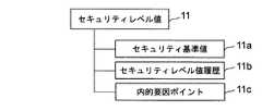
脆弱点修正情報10は、前記システム管理者21が脆弱点情報に基づいて施した脆弱点修正作業のログが、システム毎に記録されてなるものである。前記セキュリティレベル値11は、図3に示すように、セキュリティ基準値11aと、セキュリティレベル値履歴11bと、内的要因ポイント11cからなる。セキュリティ基準値11aは、組織の経営者(組織管理者22)に対してその組織のセキュリティレベルを示すための基準値であり、予め当該組織でセキュリティに関する事故が発生した場合の損害や株価の影響などを考慮して決定され格納される。また、セキュリティレベル値履歴11bには、過去に算出したセキュリティレベルが履歴として格納される。内的要因ポイント11cは、後で詳しく説明するようにセキュリティレベル値を求めるために用いるものである。
【0029】
一方、脆弱点DB3には、脆弱点情報4として、図4に示すように、脆弱点の概要情報を含む脆弱点概要情報25と、当該脆弱点による脅威について記述した脅威情報26と、当該脆弱点を修正するための脆弱点パッチ情報27と、前記修正を実際のシステムで検証した結果を記述する脆弱点検証情報28と、各脆弱点情報の脅威に関して重み付けをするための脅威レベル値29が格納されている。これらの情報の生成は、図5に示すように、このシステム1の運営者が、まず、外部ベンダーから主に英語で提供された脆弱点情報やパッチ情報を収集、翻訳し(ステップS1)、技術的な検証をする(ステップS2)。そして、各脆弱点情報に独自の脅威レベル値29を付し(ステップS3)、前記脆弱点DB3を更新する(ステップS4)。このDB3の更新は、前記DB更新部5を通して行う。
【0030】
一方、前記脆弱点監視処理部4は、図1に示すように、このシステム1にアクセスするユーザの認証を行うユーザ認証部30と、システム管理者21等から環境情報7及び管理者情報8の入力を受け付けてこれらを更新する環境情報/管理者情報/組織情報登録部31と、前記脆弱点DB3から脆弱点情報24を取り出して前記システム管理者21に提供する脆弱点情報提供部32と、システム管理者21からこのシステム管理者21が前記脆弱点情報24に基づいて施した修正作業記録の入力を受取り前記脆弱点修正情報10として記録する脆弱点修正作業ログ記録部33と、この修正情報10に基づいて脆弱点対策情報を生成し、前記組織の管理者(経営者22)にレポートする脆弱点対策情報作成部34と、前記脆弱点情報24とこれに対する修正情報10に基づいて当該組織のセキュリティレベルを算出するセキュリティレベル算出部35と、算出したセキュリティレベルに基づく情報を前記組織管理者(経営者22)に提供するセキュリティレベル情報作成部36とを有する。
【0031】
これらの構成要素は、実際には、一般的なコンピュータシステムに設けられたハードディスク等の記憶媒体にインストールされた1又は2以上のコンピュータソフトウエアプログラムによって実現され、このコンピュータソフトウエアプログラムは前記コンピュータシステムのCPUによってRAM上に呼び出され適宜実行されることでこの発明の機能を奏するようになっている。
【0032】
以下、上記構成要素の構成及び機能の詳しい説明を、図6以下の画面構成図に基づき、実際の動作を参照して説明する。
【0033】
図6は、このシステム1へのログイン画面の例である。
【0034】
例えば、前記システム管理者21が前記システム1に接続する場合、自己の端末からインターネット等を通して接続し、このログイン画面を立上げる。そして、このログイン画面のユーザ名入力ボックス40およびパスワード入力ボックス41にそれぞれ必要な情報を入力し、「Go」ボタン42を押す。このことで、前記ユーザ認証部30が当該システム管理者21の認証を行い、この監視システム1への接続を確立する。
【0035】
接続者がシステム管理者21である場合、前記脆弱点情報提供部32が前記の認証結果に従い、図7に示す画面を前記システム管理者21の端末上に表示させる。この画面には、修正ソフトウエアの適用を推奨するコンピュータ群44が表示されている。このような表示を行わせるためには、前記監視対象コンピュータシステム6の環境情報7が前記ユーザシステムDB2に適切に登録されている必要がある。この環境情報の入力及び更新を行うには、この図7の画面の環境登録ボタン45を押す。
【0036】
このボタン45が押されると、前記環境情報/管理者情報/組織情報登録部31が、図8に示す画面を表示する。システム管理者21はこの画面を通してこの監視対象のコンピュータシステムの環境情報を入力することができる。この実施例では、この画面のコンピュータリスト46に示されるように、このシステム管理者21の属する組織は、東京本社と名古屋工場とを有し、東京本社には監視対象としてMA‐T1、MA‐T2、MA‐T3の3台のコンピュータが、名古屋工場にはMA‐N1、MA‐N2、MA‐N3の3台のコンピュータがそれぞれ設けられネットワークに接続されている。
【0037】
この画面に示すのは、このうちMA‐T1に関するシステム環境情報である。この画面を通し、図2で説明した各情報12〜19を各システム毎に入力していく。ここで、システム管理者の登録は必須であり、このシステム管理者情報の編集はこの図に47で示す管理者登録ボタンを押すことによって行えるようになっている。
【0038】
また、この実施形態においては、この画面に、自動診断ボタン48が設けられており、この自動診断ボタン48を押すことで、前記した各情報を自動的に監視対象コンピュータシステム6から取得することができるようになっている。すなわち、図1に示すように、前記コンピュータシステム6には、このコンピュータシステム6の環境情報を取得する環境情報取得システム60が接続されている。そして、前記ボタン48が押されることで、前記前記環境情報/管理者情報/組織情報登録部31が前記環境情報取得システム60を起動して前記コンピュータシステム6の環境情報の全て若しくは一部を取得させることができるようになっている。
【0039】
脆弱点情報提供部32は、システム管理者21がこの脆弱点監視システム1にアクセスして来たならば、上記のようにして登録されたユーザシステムDB2内の環境情報7と前記脆弱点DB3内の脆弱点情報24とのマッチングを行う。そして、この脆弱点DB3内に前記システム6のハードウエア構成等に適合する脆弱点情報24があったならば、このコンピュータをセキュリティ対策の必要なコンピュータとしてピックアップして、図7に示す画面の符号44で示す一覧に表示する。この例では、前記した全てのコンピュータが、脆弱点修正の必要なコンピュータシステムとしてピックアップされている。このことで、各脆弱点情報24が各監視対象のコンピュータシステムに関連付けられることになる。
【0040】
システム管理者21は、この画面から、脆弱点一覧ボタン49を押すことで図9に示すように脆弱点一覧50を閲覧することができる。この脆弱点の一覧表示は、前記属性情報12に基づき、システム種別を基準として表示することもできるし、OSを基準として表示することもできるし、ロケーションを基準として表示することもできる。そして、この画面から各脆弱点をクリックすることで、さらに詳細な情報にアクセスすることができる。この場合、前記脆弱点情報提供部32は、前記脆弱点DB3から図3に示す25〜28の各詳細情報を取り出し、図10に示すように表示する。
【0041】
このことでこのシステム管理者21はこの脆弱点の詳細を確認し、対策の要否を検討することが可能になる。この脆弱点を確認した後、この対策を採った場合には、この画面の作業ログボタン51を押すことで、脆弱点修正作業の記録の入力を行う。
【0042】
図11は、この作業ログの入力画面である。この画面には、選択に係る脆弱点の修正に必要な作業が時系列的に列挙されており、システム管理者21は、各必要な作業を採ったかを確認し、実施日を入力していく。
【0043】
このように入力された脆弱点修正作業は、前記脆弱点修正作業ログ記録部33によって前記ユーザシステムDB2内に前記脆弱点修正情報10として格納される。そして、図11に列挙された全ての作業が終了した場合には、この対応が済んだものとして記録されることになる。なお、この画面には、「対象外」ボタン52と、「暫定措置」ボタン53が設けられている。前記脆弱点情報が当該システムに対応しないものであるときには、この対象外ボタン52を押すことで処理済みとすることができる。また、暫定措置ボタン53は、脆弱点に対応する有効なパッチが提供されておらず、後で対応する場合等に使用する。
【0044】
次に、前記組織管理者22がこの脆弱点監視システム1に接続する場合について説明する。
【0045】
前記組織管理者22がこのシステムにログインした場合、前記ユーザ認証部30は、前記組織情報9に基づいて、組織管理者22であることを検出する。このことに基づき、前記脆弱点情報提供部32は、図12に示すように、組織管理者22向けに、脆弱点対策情報を生成して提示する。この脆弱点対策情報は、この画面に示されるように、例えば、管理者毎、システム毎に、脆弱点情報と、その情報の発効日、対策を採った対応日を含む。対策をとった対応日は、前記修正情報10から取得して表示されることになる。また、未だ対策をとっていない脆弱点に基づき、前記脆弱点DB3から、脅威情報26等を取り出し、この画面に54で示すように表示する。
【0046】
このような画面により、組織管理者22は、自己の組織に係るネットワーク若しくはこのネットワークに接続されたコンピュータシステムのセキュリティ管理状況を確認することが可能になる。また、このシステムは、システム管理者21の採った修正作業を記録しておき、これを組織管理者22に提示するようにしたから、この組織管理者22は、システム管理者21を適切に管理することができる。
【0047】
また、図12の画面から、改善状況の表示ボタン55を押すと、前記セキュリティレベル算出部35が起動し、各脆弱点毎のセキュリティレベルを算出する。また、このセキュリティレベル算出部35は、脆弱点間、コンピュータ間のセキュリティレベル値を比較してコンピュータ毎及びネットワーク毎のセキュリティレベル値を算出するためのセキュリティレベル値比較部59を有する。
【0048】
図13に示すように、前記セキュリティレベルは、第1のグラフ56と第2のグラフ57の2つのグラフで示される。
【0049】
第1のグラフ56は、修正プログラム適用率である。各脆弱点情報の発効日付別に、適用した修正プログラムの数が、棒グラフで示されている。このグラフは、発効日を基準とするから、先月発効した脆弱点情報は、当月に修正作業を行ったとしても、先月分としてカウントされる。
【0050】
第2のグラフ57は、前記修正結果に基づく、セキュリティレベルの変化を示す折れ線グラフである。以下、この第2のグラフ57の表示手順について説明する。
【0051】
まず、この実施形態では、セキュリティレベルは、「内的要因」、「外的要因」及び「その他」からなるものと定義される。
【0052】
内的要因とは、セキュリティポリシーの有無や日々の運用状況、ネットワーク構成やセキュリティ機器の設置、設置状況等により評価される静的な値である。この内的要因は、例えば、3月若しくは半年に一回、セキュリティコンサルタントがチェックシートによって行った評価により導き出される。
【0053】
外的要因とは、日々新たに発見される脆弱点情報により求められる動的な値である。この外的要因は、基本的に、脆弱点情報の対象となっている機器の種別、前記脆弱点情報中の脅威レベル値、この脆弱点情報が発効してから何日経過しているかの情報に基づいて、前記組織管理者がアクセスする毎に算出される。
【0054】
セキュリティレベルの算入割合は、内的要因を70パーセント、外的要因を20パーセント、その他を10パーセントとする。ただし、その他は、人為的なミス等を表しているので、この実施形態では評価対象外とする。したがって、この実施形態では、内的要因の最高値70ポイント、外的要因の最高値20ポイントの合計最高点90ポイントとしてセキュリティレベル値を算出する。なお、前述したように、内的要因ポイントは、予め算出され、前記ユーザシステムDB2内に格納されている。
【0055】
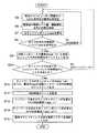
図14は、前記セキュリティレベル算出部35によるセキュリティレベル値算出工程を示すフローチャートである。
【0056】
この実施形態では、ネットワーク全体のセキュリティレベルを導き出すのに、まず、図14のステップS5〜S9で、このネットワークに属する複数のコンピュータ毎のセキュリティレベルを算出する。そして、ステップS10〜S14で、このコンピュータ毎のセキュリティレベルを比較し最低のものをネットワークのセキュリティレベルとして採用する。
【0057】
このため、前記セキュリティレベル算出部35は、まず、ネットワークに属する複数のコンピュータのうちの1番目(n=1)のコンピュータの1番目の脆弱点情報から処理を開始する(ステップS5)。
【0058】
そして、ユーザシステムDB2から、当該コンピュータ(機器)の種別情報、前記脆弱点情報の脅威レベル値、この脆弱点情報が発行してから何日経過しているかの情報を取得し(ステップS6)、以下の式により、この脆弱点情報に関する外的要因ポイント値wppを算出する(ステップS7)。
【0059】
Wpp=20+hp×hk×il×date
・ここでWppは、値が低いほど脅威が大きいことを意味する。
・hpは、基準パラメータであり、ここでは−1とする。
・hkは、コンピュータ種別(機種種別)であり、セキュリティ機器については2点、その他の機器については1点とする。
・ilは当該脆弱点情報に付加された前記脅威レベル値(図4の符号29参照)であり、三段階に設定され、Sは4点、Aは2点、Bは1点とされている。
・dateは、これまでに対応せずに経過した日数であり、前記脆弱点情報が発効した日と現在との差により求める。
【0060】
この外的要因ポイント値wppを、当該システムに適用された全ての未対応の脆弱点について求め(ステップS8)、その中で、最も値の小さいものを、当該コンピュータシステムの外的要因ポイント値wpp(n)として出力する(ステップS9)。
【0061】
また、当該組織内のネットワークに属する全てのコンピュータシステムに対しても、同様に外的要因ポイント値wpp(n)を求めていく(ステップS10)。このようにして、全てのコンピュータシステムについての処理が終了したならば、ネットワーク中で最小のwppを、ネットワーク全体の外的要因ポイント値wpp(all)とする(ステップS11)。
【0062】
ついで、前記セキュリティレベル算出部35は、前記セキュリティレベル値11から内的要因ポイント11cを取得し(ステップS12)、これに、前記外的要因ポイントwpp(n)及びwpp(all)を加算することで、セキュリティレベル値(SP)を算出する(ステップS13、S14)。
【0063】
次に、前記セキュリティレベル情報作成部36が、セキュリティレベル値SPと前記セキュリティ基準値11a及びセキュリティレベル値履歴11bを用いて図13に示す第2のグラフ57を作成する(ステップS15)。
【0064】
すなわち、この実施形態では、前記セキュリティレベル情報作成部36は、前記セキュリティレベル値履歴11bから、過去1年間の各月の末日のセキュリティレベル値を取り出し、それを各月のセキュリティレベル値とする。そして、現在求めたセキュリティレベル値SPを当月のセキュリティレベル値とする。そして、これらのセキュリティレベル値を、図13に示すように、前記セキュリティ基準値を中心値とする折れ線グラフ57として表示する。
【0065】
このような折れ線グラフによれば、専門知識の少ない経営者であっても、当該組織のセキュリティレベル値を一目で評価することが可能になる。
【0066】
なお、この発明は、上記一実施形態に限定されるものではなく、発明の要旨を変更しない範囲で種々変形可能である。
【0067】
例えば、上記一実施形態では、システム管理者及び組織管理者は、インターネット等を通して前記脆弱点監視システムから各種情報を受け取るようにしたが、これに限定されるものではない。例えば、E−mail等の手段で各種情報を提供するようにしても良い。
【0068】
また、前記セキュリティレベルの表示は、棒グラフ及び折れ線グラフで行うようにしたが、これに限定されるものではなく、具体的な数値を示すことで行なうようにしても良い。さらに、前記セキュリティレベルの具体的な算出方法は、この発明の要旨の範囲で種々変更可能である。例えば、内的要因ポイント利用せず、外的要因ポイントwpp、wpp(n)、wpp(all)により求めたセキュリティレベルのみを提供するようにしても良い。
【0069】
【発明の効果】
以上説明した構成によれば、セキュリティに関して十分な知識を有さない者であっても理解できるようなセキュリティ情報を簡便な構成で迅速に提供することができる。
【図面の簡単な説明】
【図1】この発明の一実施形態を示す概略構成図。
【図2】コンピュータシステム環境情報の構成を説明するための図。
【図3】セキュリティレベル値の構成を説明するための図。
【図4】脆弱点情報の構成を説明するための図。
【図5】脆弱点DBの更新工程を示す工程図。
【図6】ログイン画面を示す図。
【図7】システム管理者に対する情報提供画面を示す図。
【図8】環境情報登録画面を示す図。
【図9】脆弱点情報の一覧画面を示す図。
【図10】脆弱点情報の詳細画面を示す図。
【図11】脆弱点修正作業の入力画面を示す図。
【図12】組織管理者に対する情報提供画面を示す図。
【図13】組織管理者に対するセキュリティレベル情報の提供画面を示す図。
【図14】セキュリティレベル値の算出工程を示すフローチャート。
【符号の説明】
1…脆弱点監視システム
2…ユーザシステムDB
3…脆弱点DB
4…脆弱点監視処理部
5…DB更新部
6…監視対象コンピュータシステム
7…コンピュータシステム環境情報
8…システム管理者情報
9…組織情報
10…脆弱点修正情報
11…セキュリティレベル値
11a…セキュリティ基準値
11b…セキュリティレベル値履歴
11c…内的要因ポイント
12…属性情報
13…ハードウエア構成
14…ソフトウエア構成
15…設定
16…利用ネットワーク技術
17…関連機器
18…ミラーリング
19…セキュリティ対策情報
21…システム管理者
22…組織管理者
24…脆弱点情報
25…脆弱点概要情報
26…脅威情報
27…脆弱点パッチ情報
28…脆弱点検証情報
29…脅威レベル値
30…ユーザ認証部
31…環境情報/管理者情報/組織情報登録部
32…脆弱点情報提供部
33…脆弱点修正作業ログ記録部
34…脆弱点対策情報作成部
35…セキュリティレベル算出部
36…セキュリティレベル情報作成部
56…第1のグラフ
57…第2のグラフ
59…セキュリティレベル値比較部
60…環境情報取得システム[0001]
BACKGROUND OF THE INVENTION
The present invention relates to a method and system capable of accurately evaluating and providing a security level of a group of computer systems connected to a network in real time, for example.
[0002]
[Prior art]
Recently, damages such as attacks on networks and servers of corporations and government offices and infection with new viruses have occurred frequently. For this reason, attention has been focused on strengthening network security. In order to strengthen network security, it is necessary to keep track of the security level of the network and its own devices connected to the network.
[0003]
Parameters for evaluating security levels include static elements such as network and computer hardware and software configurations, and dynamic elements that occur in response to vulnerability information that occurs daily and respond to it. There is. For companies that use IT for business activities, management risks will become infinite if they do not respond quickly to this dynamic factor, so management is also a very important issue for managers. ing.
[0004]
[Problems to be solved by the invention]
Conventionally, however, it is left to the system administrator to grasp the security level, and the manager has to believe in the report from the system administrator. On the other hand, the security level may be lowered due to negligence of the system administrator, and it is very difficult to manage the security level including such factors.
[0005]
On the other hand, it is extremely difficult for managers themselves to find and grasp information necessary for their systems from a vast amount of security information, and to take countermeasures without time lag because it is technically difficult.
[0006]
The present invention has been made in view of such circumstances, and the work taken by the system administrator for security information that can be understood even by a manager or other person who does not have sufficient knowledge about security. It is an object of the present invention to provide a system and method that can be provided promptly, reflecting the above.
[0007]
[Means for Solving the Problems]
In order to solve the above-described problem, according to a first main aspect of the present invention, there is provided a method for providing security level information of a specific device by acomputer system , thecomputer system including environmental information of the specific device. And a vulnerability information storage unit for storing vulnerability information including threat level values for weighting the threats of vulnerabilities, and (a)computer system vulnerability The point information providing unit identifies avulnerabilityincluding the threat level value for the devicefrom the vulnerability information storage unit based on the environment information ofthe specific devicestored in the environment information storage unit, and this vulnerability The step of associating the information with the device,and (b)the security level calculation unit of the computer system Threat level value vulnerabilities not yet taken measures for this device,and the unsupporteddays, calculating a security level value regarding the vulnerability of thedevice,generating the security level information(c)Computer system part is, on the basis of the security level value determined in step(b), the security level information providing methodcharacterized bycomprising the step ofgenerating and outputting a security level informationof the device is provided.
[0008]
According to such a configuration, when there is unsupported vulnerability information, the security level value is calculated based on the device type, the threat level of the vulnerability, and the number of unsupported days. Can be generated.
[0009]
In addition, this method further includes: (d) when there are a plurality of unsupported vulnerabilities associated with the device,the security level comparison unit of the computer system compares the securitylevel values for the respective vulnerabilities, And calculating the securitylevel value with the highest threatlevel among the securitylevel values as the securitylevel value of the device, and the step (c) outputs security level information based on the securitylevel value of the device. It is preferable that
[0010]
According to such a configuration, when there are a plurality of pieces of vulnerability information associated with a specific device, the security value based on the vulnerability information having the highest threat level can be set as the security value of the device.
[0011]
In this case, further, (e) when there are a plurality of devices connected to the network,the security level comparison unit of the computer system compares the securitylevel values for each device, and the securitylevel value of each device has the highest threat level. and a step of calculating a high securitylevel value as the securitylevel value of the network, the step (c) is preferably outputs a security level information based on the securitylevel value of the network.
[0012]
According to such a configuration, when a plurality of devices are connected to the network, the security value of the entire network can be calculated based on the security value of each device obtained as described above.
[0013]
Further, according to one embodiment of the present invention, the step (c) is based on the securitylevel value obtained in the step (b) and the basic security information calculated based on the basic configuration of the device and the network. Securitylevel information.
[0014]
According to still another embodiment, in the step (c), in the step (c), thesecurity level information generating unit compares the securitylevel value with a security reference value of aspecific device or a network to which thedevice is connected. The process of expressing is included.
[0015]
According to such a configuration, the reference value of the security value to be satisfied by the system or network is determined, and the current security value can be expressed by comparison with the reference value. As a result, even managers who do not clearly understand the standard value of their security level can easily understand because the current security level is expressed in relation to the standard value. .
[0016]
According to a second main aspect of the present invention, there is provided a system for calculating the security level of a computer system, an environment information storage unit for storing environment information of a computer system to be monitored, various updated vulnerabilities A vulnerability information storage unit that stores information including at least the threat level value of the vulnerability, and the vulnerability information to be applied to the monitored computer system based on the environment information. About the vulnerability information provider that extracts information from the department and associates it with this computer system, the vulnerability correction information storage that stores information on whether the system administrator has taken corrective actions based on this vulnerability information, and specific devices , The device type, the threat level value of the vulnerabilities for which this measure has not been taken, and the number of unsupported days A security level calculation unit that calculates a security level value related to the vulnerability of the security level, and a security level information generation unit that generates and outputs security level information based on the security level value obtained by the calculation unit A security level information providing system is provided.
[0017]
According to such a configuration, a system capable of executing the method according to the first aspect of the present invention is provided.
[0018]
Note that this system further, if unsupported vulnerabilities associated with the apparatus there is a plurality, comparing the securitylevel values for each vulnerability, most CR securitylevel of the securitylevel value of each vulnerability has a security level value comparison section for calculating a value as a securitylevel value of the device, the security level information generating unit is preferably one which generates a security level information based on the securitylevel value of the device. In this case, the security level value comparing unit, when connected to the network devices have multiple compares the securitylevel values for each device, the the highest threat score securitylevel value of the securitylevel value of each device It is preferably calculated as a network securitylevel value, and the security level information generation unit preferably outputs security level information based on the securitylevel value of the network.
[0019]
According to another embodiment of the present invention, the security level information generation unit is configured to calculate a basic security calculated based on a securitylevel value obtained by the securitylevel calculation unit and a basic configuration of a device or a network. Security information is output based on the information.
[0020]
Furthermore, according to another embodiment of the present invention, the security level information generation unit represents the securitylevel value by comparing with a security reference value of aspecific device or a network to which thedevice is connected. It is desirable that
[0021]
The other features and remarkable effects of the present invention will be understood more clearly by referring to the following embodiments of the present invention and the attached drawings.
[0022]
DETAILED DESCRIPTION OF THE INVENTION
Hereinafter, embodiments of the present invention will be described with reference to the drawings.
[0023]
1 is a security level information providing system according to this embodiment, and FIG. 1 is a schematic configuration diagram of the system 1. In FIG.
[0024]
The system 1 includes a
[0025]
The
[0026]
As the computer system environment information 7, as shown in FIG. 2, in addition to the
[0027]
The system administrator information 8 shown in FIG. 1 stores the name of the administrator (indicated by 21 in FIG. 1) of the
[0028]
The
[0029]
On the other hand, as shown in FIG. 4, the
[0030]
On the other hand, as shown in FIG. 1, the vulnerability monitoring processing unit 4 includes a
[0031]
These components are actually realized by one or more computer software programs installed in a storage medium such as a hard disk provided in a general computer system, and the computer software program is the computer system. The functions of the present invention are achieved by being called on the RAM by the CPU and appropriately executed.
[0032]
Hereinafter, a detailed description of the configuration and functions of the above-described components will be described with reference to the actual operation based on the screen configuration diagram of FIG.
[0033]
FIG. 6 is an example of a login screen to the system 1.
[0034]
For example, when the
[0035]
When the connected person is the
[0036]
When this
[0037]
This screen shows system environment information related to MA-T1. Through this screen, the
[0038]
In this embodiment, an
[0039]
When the
[0040]
The
[0041]
As a result, the
[0042]
FIG. 11 shows an input screen for this work log. In this screen, the work necessary for correcting the vulnerability related to the selection is listed in time series, and the
[0043]
The vulnerability correction work input in this way is stored as the
[0044]
Next, a case where the
[0045]
When the
[0046]
With such a screen, the
[0047]
When the improvement
[0048]
As shown in FIG. 13, the security level is represented by two graphs, a
[0049]
The
[0050]
The
[0051]
First, in this embodiment, the security level is defined as consisting of “internal factor”, “external factor”, and “other”.
[0052]
The internal factor is a static value evaluated based on the presence / absence of a security policy, daily operation status, network configuration, installation of security devices, installation status, and the like. This internal factor is derived, for example, by an evaluation performed by a security consultant using a check sheet once every March or half year.
[0053]
An external factor is a dynamic value obtained from vulnerability information that is newly discovered every day. This external factor is basically the type of device that is the target of vulnerability information, the threat level value in the vulnerability information, and information on how many days have passed since this vulnerability information became effective. Is calculated every time the organization manager accesses.
[0054]
The security level includes 70% for internal factors, 20% for external factors, and 10% for others. However, since others represent human errors and the like, they are not evaluated in this embodiment. Therefore, in this embodiment, the security level value is calculated as a total maximum score of 90 points including the maximum value of internal factors of 70 points and the maximum value of external factors of 20 points. As described above, the internal factor points are calculated in advance and stored in the user system DB2.
[0055]
FIG. 14 is a flowchart showing a security level value calculation process by the security
[0056]
In this embodiment, in order to derive the security level of the entire network, first, security levels for a plurality of computers belonging to this network are calculated in steps S5 to S9 in FIG. In steps S10 to S14, the security levels of the computers are compared, and the lowest one is adopted as the network security level.
[0057]
Therefore, the security
[0058]
Then, the type information of the computer (device), the threat level value of the vulnerability information, and information on how many days have passed since the vulnerability information was issued are obtained from the user system DB2 (step S6). The external factor point value wpp relating to this vulnerability information is calculated by the following equation (step S7).
[0059]
Wpp = 20 + hp × hk × il × date
Here, Wpp means that the lower the value, the greater the threat.
Hp is a reference parameter, and is −1 here.
Hk is a computer type (model type), 2 points for security devices and 1 point for other devices.
Il is the threat level value (see
Date is the number of days that have passed without being handled so far, and is obtained from the difference between the date when the vulnerability information is effective and the current date.
[0060]
The external factor point value wpp is obtained for all unsupported vulnerabilities applied to the system (step S8), and the smallest value is determined as the external factor point value wpp of the computer system. (N) is output (step S9).
[0061]
Further, the external factor point value wpp (n) is similarly obtained for all computer systems belonging to the network in the organization (step S10). When the processing for all the computer systems is completed in this way, the smallest wpp in the network is set as the external factor point value wpp (all) for the entire network (step S11).
[0062]
Next, the security
[0063]
Next, the security level
[0064]
In other words, in this embodiment, the security level
[0065]
According to such a line graph, even a manager with little expertise can evaluate the security level value of the organization at a glance.
[0066]
In addition, this invention is not limited to the said one Embodiment, A various deformation | transformation is possible in the range which does not change the summary of invention.
[0067]
For example, in the above-described embodiment, the system administrator and the organization administrator receive various information from the vulnerability monitoring system through the Internet or the like, but the present invention is not limited to this. For example, various types of information may be provided by means such as E-mail.
[0068]
The security level is displayed as a bar graph or a line graph. However, the present invention is not limited to this, and may be performed by showing specific numerical values. Further, the specific method for calculating the security level can be variously changed within the scope of the gist of the present invention. For example, only the security level obtained by the external factor points wpp, wpp (n), and wpp (all) may be provided without using the internal factor points.
[0069]
【The invention's effect】
According to the configuration described above, security information that can be understood even by a person who does not have sufficient knowledge about security can be quickly provided with a simple configuration.
[Brief description of the drawings]
FIG. 1 is a schematic configuration diagram showing an embodiment of the present invention.
FIG. 2 is a diagram for explaining the configuration of computer system environment information.
FIG. 3 is a view for explaining the configuration of security level values;
FIG. 4 is a diagram for explaining the configuration of vulnerability information.
FIG. 5 is a process diagram showing a vulnerability DB update process.
FIG. 6 is a diagram showing a login screen.
FIG. 7 is a diagram showing an information provision screen for a system administrator.
FIG. 8 is a diagram showing an environment information registration screen.
FIG. 9 is a diagram showing a list screen of vulnerability information.
FIG. 10 is a diagram showing a detailed screen of vulnerability information.
FIG. 11 is a diagram showing an input screen for vulnerability correction work.
FIG. 12 is a diagram showing an information provision screen for an organization manager.
FIG. 13 is a diagram showing a screen for providing security level information to an organization administrator.
FIG. 14 is a flowchart showing a security level value calculation process.
[Explanation of symbols]
1 ...
3 ... Vulnerability DB
4 ... Vulnerability monitoring processing unit 5 ...
Claims (10)
Translated fromJapaneseこのコンピュータシステムは、前記特定の機器の環境情報を格納する環境情報格納部と、脆弱点の脅威に関して重み付けをするための脅威レベル値を含む脆弱点情報を格納する脆弱点情報格納部とを備え、
この方法は、
(a)コンピュータシステムの脆弱点情報提供部が、前記環境情報格納部に格納された特定の機器の環境情報に基づいて、前記脆弱点情報格納部からこの機器について前記脅威レベル値を含む脆弱点を特定し、この脆弱点の情報を前記機器に関連付ける工程と、
(b)コンピュータシステムのセキュリティレベル算出部が、特定の機器について、この機器の種別、この機器について未だ対策を採っていない脆弱点の脅威レベル値、及び未対応の日数から、当該機器の当該脆弱点に関するセキュリティレベル値を算出する工程と、
(c)コンピュータシステムのセキュリティレベル情報生成部が、前記(b)工程で求めたセキュリティレベル値に基づいて、この機器のセキュリティレベル情報を生成して出力する工程と
を備えたことを特徴とするセキュリティレベル情報提供方法。A method of providing security level information of a specific device by a computer system,
The computer system includes an environment information storage unit that stores environment information of the specific device, and a vulnerability information storage unit that stores vulnerability information including a threat level value for weighting the vulnerability threat. ,
This method
(A)The vulnerability information providing unit of the computer systemincludes the threat level value for the devicefrom the vulnerability information storage unit based on the environment information ofthe specific devicestored in the environmentinformation storage unit. identifythe steps of correlating the information in this vulnerability in the device,
(B)security level calculation unit of the computer system for a particular device, the type of the equipment, the threat level value vulnerabilities not yet taken measures for this device,and the unsupporteddays, the fragility of the device Calculating a security level value for the point;
(C)The security level information generation unit of the computer systemincludes a step ofgenerating and outputtingthe security level information of thedevice based on the security level value obtained in the step (b). Security level information provision method.
さらに、
(d)コンピュータシステムのセキュリティレベル比較部が、当該機器に関連付けられた未対応の脆弱点が複数ある場合、各脆弱点に関するセキュリティレベル値を比較し、各脆弱点のセキュリティレベル値のうち最も脅威度の高いセキュリティレベル値を当該機器のセキュリティレベル値として算出する工程を有し、
前記(c)工程は、当該機器のセキュリティレベル値に基づいてセキュリティレベル情報を出力するものであることを特徴とするセキュリティレベル情報提供方法。In the security level information provision method of Claim 1,
further,
(D) When there are a plurality of unsupported vulnerabilities associated with the device,the security level comparison unit of the computer system compares the securitylevel values for each vulnerability, and the most threat among the securitylevel values for each vulnerability the degree of high securitylevel value has a step of calculating as a securitylevel value of the device,
The step (c) outputs security level information based on a securitylevel value of the device, and provides a security level information providing method.
さらに、
(e)コンピュータシステムのセキュリティレベル比較部が、ネットワークに接続された機器が複数ある場合、各機器に関するセキュリティレベル値を比較し、各機器のセキュリティレベル値のうち最も脅威度の高いセキュリティレベル値を当該ネットワークのセキュリティレベル値として算出する工程を有し、
前記(c)工程は、当該ネットワークのセキュリティレベル値に基づいてセキュリティレベル情報を出力するものであることを特徴とするセキュリティレベル情報提供方法。The security level information providing method according to claim 2,
further,
Security level comparator of the (e)computer system, if the device connected to the network there are multiple, compares the securitylevel values for each device, the highest threat score securitylevel value of the securitylevel value of each device A step of calculating as a securitylevel value of the network;
Step (c) is a method for providing security level information, characterized in that security level information is output based on the securitylevel value of the network.
前記(c)工程は、
(b)工程で求めたセキュリティレベル値と、機器やネットワークの基本構成等に基づいて算出した基本セキュリティ情報とに基づいてセキュリティレベル情報を出力するものであることを特徴とするセキュリティレベル情報提供方法。In the security level information provision method of Claim 1,
The step (c)
(B) A security level information providing method that outputs securitylevel information based on the securitylevel value obtained in the step and the basic security information calculated based on the basic configuration of the device or network. .
前記(c)工程は、セキュリティレベル情報生成部が、特定の機器若しくはこの機器が接続されたネットワークのセキュリティ基準値との比較で前記セキュリティレベル値を表現する工程を含むものであることを特徴とするセキュリティレベル情報提供方法。In the security level information provision method of Claim 1,
The step (c) includes a step in which thesecurity level information generation unit expresses the securitylevel value by comparing with a security reference value of aspecific device or a network to which thedevice is connected. Level information provision method.
監視対象のコンピュータシステムの環境情報を格納する環境情報格納部と、
更新された各種脆弱点情報であって少なくとも脆弱点の脅威レベル値を含む情報を格納する脆弱点情報格納部と、
前記環境情報に基づいて当該監視対象のコンピュータシステムに適用すべき脆弱点情報を前記脆弱点情報格納部から抽出し、このコンピュータシステムに関連付ける脆弱点情報提供部とこの脆弱点情報に基づいてシステムの管理者が修正作業を採ったかの情報を格納する脆弱点修正情報格納部と、
特定の機器について、この機器の種別、この機器について未だ対策を採っていない脆弱点の脅威レベル値、未対応の日数から当該機器の当該脆弱点に関するセキュリティレベル値を算出するセキュリティレベル算出部と、
前記算出部で求めたセキュリティレベル値に基づいてセキュリティレベル情報を生成し出力するセキュリティレベル情報生成部とを有することを特徴とするセキュリティレベル情報提供システム。A system for calculating the security level of a computer system,
An environment information storage for storing environment information of the monitored computer system;
Vulnerability information storage unit for storing various types of updated vulnerability information and information including at least the threat level value of the vulnerability;
Vulnerability information to be applied to the monitored computer system based on the environment information is extracted from the vulnerability information storage unit, and the vulnerability information providing unit associated with the computer system and the system information based on the vulnerability information are extracted. Vulnerability correction information storage unit that stores information on whether the administrator has taken correction work,
For a specific device, a security level calculation unit that calculates the type of this device, the threat level value of the vulnerability that has not yet been addressed for this device, and the security level value for the vulnerability of the device from the number of unsupported days,
A security level information providing system comprising: a security level information generation unit that generates and outputs security level information based on the security level value obtained by the calculation unit.
さらに、
当該機器に関連付けられた未対応の脆弱点が複数ある場合、各脆弱点に関するセキュリティレベル値を比較し、各脆弱点のセキュリティレベル値のうち最も脅威度の高いセキュリティレベル値を当該機器のセキュリティレベル値として算出するセキュリティレベル値比較部を有し、
前記セキュリティレベル情報生成部は、当該機器のセキュリティレベル値に基づいてセキュリティレベル情報を生成するものであることを特徴とするセキュリティレベル情報提供システム。The security level information providing system according to claim 6,
further,
If unsupported vulnerabilities associated with that device there are a plurality, comparing the securitylevel values for each vulnerability, the securitylevel of the device having the highest threat score securitylevel value of the securitylevel value of each vulnerability Having a security level value comparison part to calculate as a value,
The security level information providing system, wherein the security level information generating unit generates security level information based on a securitylevel value of the device.
前記セキュリティレベル値比較部は、ネットワークに接続された機器が複数ある場合、各機器に関するセキュリティレベル値を比較し、各機器のセキュリティレベル値のうち最も脅威度の高いセキュリティレベル値を当該ネットワークのセキュリティレベル値として算出するものであり、
前記セキュリティレベル情報生成部は、当該ネットワークのセキュリティレベル値に基づいてセキュリティレベル情報を出力するものであることを特徴とするセキュリティレベル情報提供システム。The security level information providing system according to claim 7,
The security level value comparing unit, when connected to the network devices have multiple compares the securitylevel values for each device, the most highly CR securitylevel value of the network security of the securitylevel value of each device It is calculated as alevel value,
The security level information providing system, wherein the security level information generation unit outputs security level information based on a securitylevel value of the network.
前記セキュリティレベル算出部で求めたセキュリティレベル値と、機器やネットワークの基本構成等に基づいて算出した基本セキュリティ情報とに基づいてセキュリティ情報を出力するものであることを特徴とするセキュリティレベル情報提供システム。The security level information providing system according to claim 6, wherein the security level information generation unit includes:
A security level information providing system for outputting security information based on a securitylevel value obtained by the security level calculation unit and basic security information calculated based on a basic configuration of a device or a network .
前記セキュリティレベル情報生成部は、
特定の機器若しくはこの機器が接続されたネットワークのセキュリティ基準値との比較で前記セキュリティレベル値を表現するものであることを特徴とするセキュリティレベル情報提供システム。The security level information providing system according to claim 6,
The security level information generation unit
A security level information providing system characterized in that the securitylevel value is expressed by comparison with a security reference value of aspecific device or a network to which thedevice is connected.
Priority Applications (2)
| Application Number | Priority Date | Filing Date | Title |
|---|---|---|---|
| JP2002010888AJP4190765B2 (en) | 2002-01-18 | 2002-01-18 | Security level information providing method and system |
| US10/092,814US20030140249A1 (en) | 2002-01-18 | 2002-03-07 | Security level information offering method and system |
Applications Claiming Priority (1)
| Application Number | Priority Date | Filing Date | Title |
|---|---|---|---|
| JP2002010888AJP4190765B2 (en) | 2002-01-18 | 2002-01-18 | Security level information providing method and system |
Publications (2)
| Publication Number | Publication Date |
|---|---|
| JP2003216577A JP2003216577A (en) | 2003-07-31 |
| JP4190765B2true JP4190765B2 (en) | 2008-12-03 |
Family
ID=19191625
Family Applications (1)
| Application Number | Title | Priority Date | Filing Date |
|---|---|---|---|
| JP2002010888AExpired - Fee RelatedJP4190765B2 (en) | 2002-01-18 | 2002-01-18 | Security level information providing method and system |
Country Status (2)
| Country | Link |
|---|---|
| US (1) | US20030140249A1 (en) |
| JP (1) | JP4190765B2 (en) |
Families Citing this family (33)
| Publication number | Priority date | Publication date | Assignee | Title |
|---|---|---|---|---|
| JP4222184B2 (en) | 2003-04-24 | 2009-02-12 | 日本電気株式会社 | Security management support system, security management support method and program |
| US20040221176A1 (en)* | 2003-04-29 | 2004-11-04 | Cole Eric B. | Methodology, system and computer readable medium for rating computer system vulnerabilities |
| US9118710B2 (en) | 2003-07-01 | 2015-08-25 | Securityprofiling, Llc | System, method, and computer program product for reporting an occurrence in different manners |
| US9350752B2 (en) | 2003-07-01 | 2016-05-24 | Securityprofiling, Llc | Anti-vulnerability system, method, and computer program product |
| US9100431B2 (en) | 2003-07-01 | 2015-08-04 | Securityprofiling, Llc | Computer program product and apparatus for multi-path remediation |
| US20070113272A2 (en) | 2003-07-01 | 2007-05-17 | Securityprofiling, Inc. | Real-time vulnerability monitoring |
| US8984644B2 (en) | 2003-07-01 | 2015-03-17 | Securityprofiling, Llc | Anti-vulnerability system, method, and computer program product |
| US9118709B2 (en) | 2003-07-01 | 2015-08-25 | Securityprofiling, Llc | Anti-vulnerability system, method, and computer program product |
| US9118711B2 (en) | 2003-07-01 | 2015-08-25 | Securityprofiling, Llc | Anti-vulnerability system, method, and computer program product |
| US9118708B2 (en) | 2003-07-01 | 2015-08-25 | Securityprofiling, Llc | Multi-path remediation |
| JP2011065674A (en)* | 2003-09-30 | 2011-03-31 | Fujitsu Social Science Laboratory Ltd | Management program of computer system, computer system management device, and management method of computer system |
| US7716726B2 (en)* | 2004-02-13 | 2010-05-11 | Microsoft Corporation | System and method for protecting a computing device from computer exploits delivered over a networked environment in a secured communication |
| JP2006252109A (en)* | 2005-03-10 | 2006-09-21 | Oki Electric Ind Co Ltd | Network access controller, device for remote operation and system |
| US8132260B1 (en) | 2006-06-12 | 2012-03-06 | Redseal Systems, Inc. | Methods and apparatus for prioritization of remediation techniques for network security risks |
| JP2008003873A (en)* | 2006-06-23 | 2008-01-10 | Hitachi Electronics Service Co Ltd | Security monitoring system |
| JP5125069B2 (en)* | 2006-11-16 | 2013-01-23 | 日本電気株式会社 | Security risk management system, security risk management method, and security risk management program |
| JP2008287435A (en)* | 2007-05-16 | 2008-11-27 | Toshiba Corp | Security level monitoring and evaluation apparatus and security level monitoring and evaluation program |
| JP4959425B2 (en)* | 2007-06-04 | 2012-06-20 | 株式会社リコー | Information processing apparatus, program, and information processing method |
| US8091065B2 (en)* | 2007-09-25 | 2012-01-03 | Microsoft Corporation | Threat analysis and modeling during a software development lifecycle of a software application |
| JP5332174B2 (en)* | 2007-10-22 | 2013-11-06 | 株式会社リコー | Information input system |
| JP5025433B2 (en)* | 2007-11-27 | 2012-09-12 | 株式会社東芝 | Security degradation prevention support device and security degradation prevention support program |
| US10091229B2 (en)* | 2008-01-09 | 2018-10-02 | Masergy Communications, Inc. | Systems and methods of network security and threat management |
| JP5018534B2 (en)* | 2008-02-12 | 2012-09-05 | トヨタ自動車株式会社 | Vehicle security system |
| US8621637B2 (en)* | 2011-01-10 | 2013-12-31 | Saudi Arabian Oil Company | Systems, program product and methods for performing a risk assessment workflow process for plant networks and systems |
| US9027141B2 (en)* | 2012-04-12 | 2015-05-05 | Netflix, Inc. | Method and system for improving security and reliability in a networked application environment |
| US20150207811A1 (en)* | 2012-07-31 | 2015-07-23 | Hewlett-Packard Development Company, L.P. | Vulnerability vector information analysis |
| US20150205956A1 (en)* | 2012-09-19 | 2015-07-23 | Mitsubishi Electric Corporation | Information processing apparatus, information processing method, and program |
| CN103699844B (en)* | 2012-09-28 | 2016-10-26 | 腾讯科技(深圳)有限公司 | Safety protection system and method |
| US10171510B2 (en)* | 2016-12-14 | 2019-01-01 | CyberSaint, Inc. | System and method for monitoring and grading a cybersecurity framework |
| JP7058088B2 (en)* | 2017-07-20 | 2022-04-21 | 株式会社日立製作所 | Security design support system and security design support method |
| JP7180500B2 (en)* | 2019-03-29 | 2022-11-30 | オムロン株式会社 | Control system and setting method |
| CN111274255B (en)* | 2020-01-20 | 2021-06-18 | 拉扎斯网络科技(上海)有限公司 | Business data monitoring method and system, monitoring architecture, equipment, and storage medium |
| US12058163B2 (en) | 2021-08-10 | 2024-08-06 | CyberSaint, Inc. | Systems, media, and methods for utilizing a crosswalk algorithm to identify controls across frameworks, and for utilizing identified controls to generate cybersecurity risk assessments |
Family Cites Families (14)
| Publication number | Priority date | Publication date | Assignee | Title |
|---|---|---|---|---|
| US6052695A (en)* | 1995-02-28 | 2000-04-18 | Ntt Data Communications Systems Corporation | Accurate completion of transaction in cooperative type distributed system and recovery procedure for same |
| JPH09214493A (en)* | 1996-02-08 | 1997-08-15 | Hitachi Ltd | Network system |
| US5892903A (en)* | 1996-09-12 | 1999-04-06 | Internet Security Systems, Inc. | Method and apparatus for detecting and identifying security vulnerabilities in an open network computer communication system |
| US6070244A (en)* | 1997-11-10 | 2000-05-30 | The Chase Manhattan Bank | Computer network security management system |
| US6298445B1 (en)* | 1998-04-30 | 2001-10-02 | Netect, Ltd. | Computer security |
| US6347374B1 (en)* | 1998-06-05 | 2002-02-12 | Intrusion.Com, Inc. | Event detection |
| US6185689B1 (en)* | 1998-06-24 | 2001-02-06 | Richard S. Carson & Assoc., Inc. | Method for network self security assessment |
| US6301668B1 (en)* | 1998-12-29 | 2001-10-09 | Cisco Technology, Inc. | Method and system for adaptive network security using network vulnerability assessment |
| US6205552B1 (en)* | 1998-12-31 | 2001-03-20 | Mci Worldcom, Inc. | Method and apparatus for checking security vulnerability of networked devices |
| US6883101B1 (en)* | 2000-02-08 | 2005-04-19 | Harris Corporation | System and method for assessing the security posture of a network using goal oriented fuzzy logic decision rules |
| US6535227B1 (en)* | 2000-02-08 | 2003-03-18 | Harris Corporation | System and method for assessing the security posture of a network and having a graphical user interface |
| US20010034847A1 (en)* | 2000-03-27 | 2001-10-25 | Gaul,Jr. Stephen E. | Internet/network security method and system for checking security of a client from a remote facility |
| US6807569B1 (en)* | 2000-09-12 | 2004-10-19 | Science Applications International Corporation | Trusted and anonymous system and method for sharing threat data to industry assets |
| US20020066034A1 (en)* | 2000-10-24 | 2002-05-30 | Schlossberg Barry J. | Distributed network security deception system |
- 2002
- 2002-01-18JPJP2002010888Apatent/JP4190765B2/ennot_activeExpired - Fee Related
- 2002-03-07USUS10/092,814patent/US20030140249A1/ennot_activeAbandoned
Also Published As
| Publication number | Publication date |
|---|---|
| JP2003216577A (en) | 2003-07-31 |
| US20030140249A1 (en) | 2003-07-24 |
Similar Documents
| Publication | Publication Date | Title |
|---|---|---|
| JP4190765B2 (en) | Security level information providing method and system | |
| JP4152108B2 (en) | Vulnerability monitoring method and system | |
| US11966308B2 (en) | Generation of an issue response communications evaluation regarding a system aspect of a system | |
| US11930032B2 (en) | System and method for enumerating and remediating gaps in cybersecurity defenses | |
| US8121892B2 (en) | Method, system, and computer program product for assessing information security | |
| AU2018226381A1 (en) | Cyber security analyzer | |
| US20100058114A1 (en) | Systems and methods for automated management of compliance of a target asset to predetermined requirements | |
| US20060191007A1 (en) | Security force automation | |
| KR101292640B1 (en) | Method for Risk Management using Web based RMS linked with SSO | |
| Kersten et al. | 'Give Me Structure': Synthesis and Evaluation of a (Network) Threat Analysis Process Supporting Tier 1 Investigations in a Security Operation Center | |
| Weiß et al. | A comprehensive and comparative metric for information security | |
| US20050038993A1 (en) | Information security model | |
| CN114490261A (en) | A terminal security event linkage processing method, device and device | |
| Hlaing et al. | An integrated cost-effective security requirement engineering process in SDLC using FRAM | |
| Curtis et al. | Cybersecurity capability maturity model for information technology services (c2m2 for it services), version 1.0 | |
| Fung et al. | Electronic information security documentation | |
| US20060107313A1 (en) | Method, system, and medium for the analysis of information system security | |
| Luthfi et al. | Development of Security Operation Center (SOC) Governance Blueprint Based on Consideration of Process Maturity Level Parameters | |
| TWM653259U (en) | Information security patch management equipment | |
| Evans | The Importance of Incident Response | |
| Sheppey et al. | Information Security | |
| Podhradsky | An Innovative Approach to Information Technology Risk Assessment for Small and Medium Sized Financial Institutions | |
| Ryba et al. | The methodology for detecting and managing the abuse of IT systems | |
| CA2451908A1 (en) | Information security model |
Legal Events
| Date | Code | Title | Description |
|---|---|---|---|
| A711 | Notification of change in applicant | Free format text:JAPANESE INTERMEDIATE CODE: A711 Effective date:20030313 | |
| A621 | Written request for application examination | Free format text:JAPANESE INTERMEDIATE CODE: A621 Effective date:20050117 | |
| RD04 | Notification of resignation of power of attorney | Free format text:JAPANESE INTERMEDIATE CODE: A7424 Effective date:20060413 | |
| A977 | Report on retrieval | Free format text:JAPANESE INTERMEDIATE CODE: A971007 Effective date:20080219 | |
| A131 | Notification of reasons for refusal | Free format text:JAPANESE INTERMEDIATE CODE: A131 Effective date:20080318 | |
| A521 | Request for written amendment filed | Free format text:JAPANESE INTERMEDIATE CODE: A523 Effective date:20080430 | |
| TRDD | Decision of grant or rejection written | ||
| A01 | Written decision to grant a patent or to grant a registration (utility model) | Free format text:JAPANESE INTERMEDIATE CODE: A01 Effective date:20080909 | |
| A01 | Written decision to grant a patent or to grant a registration (utility model) | Free format text:JAPANESE INTERMEDIATE CODE: A01 | |
| A61 | First payment of annual fees (during grant procedure) | Free format text:JAPANESE INTERMEDIATE CODE: A61 Effective date:20080917 | |
| FPAY | Renewal fee payment (event date is renewal date of database) | Free format text:PAYMENT UNTIL: 20110926 Year of fee payment:3 | |
| R150 | Certificate of patent or registration of utility model | Free format text:JAPANESE INTERMEDIATE CODE: R150 | |
| FPAY | Renewal fee payment (event date is renewal date of database) | Free format text:PAYMENT UNTIL: 20110926 Year of fee payment:3 | |
| FPAY | Renewal fee payment (event date is renewal date of database) | Free format text:PAYMENT UNTIL: 20120926 Year of fee payment:4 | |
| FPAY | Renewal fee payment (event date is renewal date of database) | Free format text:PAYMENT UNTIL: 20130926 Year of fee payment:5 | |
| R250 | Receipt of annual fees | Free format text:JAPANESE INTERMEDIATE CODE: R250 | |
| R250 | Receipt of annual fees | Free format text:JAPANESE INTERMEDIATE CODE: R250 | |
| R250 | Receipt of annual fees | Free format text:JAPANESE INTERMEDIATE CODE: R250 | |
| R250 | Receipt of annual fees | Free format text:JAPANESE INTERMEDIATE CODE: R250 | |
| R250 | Receipt of annual fees | Free format text:JAPANESE INTERMEDIATE CODE: R250 | |
| S531 | Written request for registration of change of domicile | Free format text:JAPANESE INTERMEDIATE CODE: R313531 | |
| R350 | Written notification of registration of transfer | Free format text:JAPANESE INTERMEDIATE CODE: R350 | |
| LAPS | Cancellation because of no payment of annual fees |