JP4190379B2 - Combined electromagnetic relay - Google Patents
Combined electromagnetic relayDownload PDFInfo
- Publication number
- JP4190379B2 JP4190379B2JP2003321496AJP2003321496AJP4190379B2JP 4190379 B2JP4190379 B2JP 4190379B2JP 2003321496 AJP2003321496 AJP 2003321496AJP 2003321496 AJP2003321496 AJP 2003321496AJP 4190379 B2JP4190379 B2JP 4190379B2
- Authority
- JP
- Japan
- Prior art keywords
- relay
- housing
- structures
- wall
- bottom edge
- Prior art date
- Legal status (The legal status is an assumption and is not a legal conclusion. Google has not performed a legal analysis and makes no representation as to the accuracy of the status listed.)
- Expired - Fee Related
Links
- 239000002131composite materialSubstances0.000claimsdescription39
- 238000004804windingMethods0.000claimsdescription28
- 238000005192partitionMethods0.000claimsdescription27
- 239000000853adhesiveSubstances0.000claimsdescription8
- 230000001070adhesive effectEffects0.000claimsdescription7
- XEEYBQQBJWHFJM-UHFFFAOYSA-NIronChemical group[Fe]XEEYBQQBJWHFJM-UHFFFAOYSA-N0.000description12
- 238000009413insulationMethods0.000description4
- 229910000831SteelInorganic materials0.000description3
- 238000003780insertionMethods0.000description3
- 230000037431insertionEffects0.000description3
- 239000000463materialSubstances0.000description3
- 239000010959steelSubstances0.000description3
- 239000007769metal materialSubstances0.000description2
- 238000011084recoveryMethods0.000description2
- 229910000906BronzeInorganic materials0.000description1
- OAICVXFJPJFONN-UHFFFAOYSA-NPhosphorusChemical compound[P]OAICVXFJPJFONN-UHFFFAOYSA-N0.000description1
- 238000013459approachMethods0.000description1
- 239000010974bronzeSubstances0.000description1
- 239000004020conductorSubstances0.000description1
- KUNSUQLRTQLHQQ-UHFFFAOYSA-Ncopper tinChemical compound[Cu].[Sn]KUNSUQLRTQLHQQ-UHFFFAOYSA-N0.000description1
- 230000000694effectsEffects0.000description1
- 239000012777electrically insulating materialSubstances0.000description1
- 238000009434installationMethods0.000description1
- 229920005989resinPolymers0.000description1
- 239000011347resinSubstances0.000description1
- 239000000758substrateSubstances0.000description1
- 229920003002synthetic resinPolymers0.000description1
- 239000000057synthetic resinSubstances0.000description1
- 230000009466transformationEffects0.000description1
Images


Classifications
- H—ELECTRICITY
- H01—ELECTRIC ELEMENTS
- H01H—ELECTRIC SWITCHES; RELAYS; SELECTORS; EMERGENCY PROTECTIVE DEVICES
- H01H50/00—Details of electromagnetic relays
- H01H50/02—Bases; Casings; Covers
- H01H50/04—Mounting complete relay or separate parts of relay on a base or inside a case
- H01H50/041—Details concerning assembly of relays
- H01H50/042—Different parts are assembled by insertion without extra mounting facilities like screws, in an isolated mounting part, e.g. stack mounting on a coil-support
- H—ELECTRICITY
- H01—ELECTRIC ELEMENTS
- H01H—ELECTRIC SWITCHES; RELAYS; SELECTORS; EMERGENCY PROTECTIVE DEVICES
- H01H50/00—Details of electromagnetic relays
- H01H50/02—Bases; Casings; Covers
- H01H50/04—Mounting complete relay or separate parts of relay on a base or inside a case
- H01H50/041—Details concerning assembly of relays
- H01H50/043—Details particular to miniaturised relays
- H01H2050/044—Special measures to minimise the height of the relay
- H—ELECTRICITY
- H01—ELECTRIC ELEMENTS
- H01H—ELECTRIC SWITCHES; RELAYS; SELECTORS; EMERGENCY PROTECTIVE DEVICES
- H01H50/00—Details of electromagnetic relays
- H01H50/02—Bases; Casings; Covers
- H01H50/04—Mounting complete relay or separate parts of relay on a base or inside a case
- H01H2050/049—Assembling or mounting multiple relays in one common housing
- H—ELECTRICITY
- H01—ELECTRIC ELEMENTS
- H01H—ELECTRIC SWITCHES; RELAYS; SELECTORS; EMERGENCY PROTECTIVE DEVICES
- H01H50/00—Details of electromagnetic relays
- H01H50/02—Bases; Casings; Covers
- H01H50/023—Details concerning sealing, e.g. sealing casing with resin
- H—ELECTRICITY
- H01—ELECTRIC ELEMENTS
- H01H—ELECTRIC SWITCHES; RELAYS; SELECTORS; EMERGENCY PROTECTIVE DEVICES
- H01H50/00—Details of electromagnetic relays
- H01H50/02—Bases; Casings; Covers
- H01H50/026—Details concerning isolation between driving and switching circuit
Landscapes
- Physics & Mathematics (AREA)
- Electromagnetism (AREA)
- Electromagnets (AREA)
Description
Translated fromJapanese本発明は、電磁継電器に関し、特に、互いに独立した継電器の構造を有する複数の継電器構造体を共通の筐体に収容してなる複合型電磁継電器に関する。 The present invention relates to an electromagnetic relay, and more particularly to a composite electromagnetic relay in which a plurality of relay structures having a structure of independent relays are accommodated in a common housing.
電磁継電器において、電磁石装置及び電磁石装置の作用により開閉動作する接点部をそれぞれに備え、互いに独立した継電器の構造を有する複数の継電器構造体を、共通する1つの筐体に並設配置で収容してなる複合型電磁継電器が知られている。この種の複合型電磁継電器は、例えばモータやソレノイドを正逆方向に頻繁に切り換えて動作させる制御回路で使用できるものであって、筐体の共通化により、互いに独立した筐体を有する複数の電磁継電器を使用する構成に比べて継電器設置空間を削減する効果を奏することから、パワーウィンドウ等の車載用電動機器類の制御回路のような、狭小な空間に回路構成部品を設置しなければならない用途で有効に使用されている。特に、複数の継電器構造体が筐体内で互いに完全に独立した継電器の構造を有する複合型電磁継電器は、一対の継電器構造体の接点部を例えば固定接点側の端子部品(すなわち固定接点部材)を共有することにより一部共通化した複合型電磁継電器とは異なり、1つの電磁継電器で複数の電動機器類を個々に適時に制御できるものである。 In an electromagnetic relay, an electromagnet device and a contact portion that opens and closes by the action of the electromagnet device are provided, and a plurality of relay structures having relay structures independent from each other are accommodated in a common housing in a side-by-side arrangement. A composite electromagnetic relay is known. This type of composite electromagnetic relay can be used in, for example, a control circuit that frequently switches motors and solenoids in forward and reverse directions to operate. Since it has the effect of reducing the relay installation space compared to a configuration using an electromagnetic relay, circuit components must be installed in a small space, such as a control circuit for in-vehicle electric devices such as power windows. It is effectively used in applications. In particular, a composite electromagnetic relay having a relay structure in which a plurality of relay structures are completely independent from each other in a housing is used to connect contact parts of a pair of relay structures, for example, terminal components on the fixed contact side (that is, fixed contact members). Unlike a composite electromagnetic relay that is partially shared by sharing, a plurality of electric devices can be individually controlled in a timely manner with a single electromagnetic relay.
この種の複合型電磁継電器において、互いに独立した複数の継電器構造体を、それぞれの接点部が交互に反対側に位置するように逆向きに配置して、1つの筐体に収容したものが提案されている(例えば特許文献1参照)。複数の継電器構造体をこのように互いに逆向きに配置すれば、個々の継電器構造体に設けられるコイル端子対が、互いに離隔した位置で筐体から突出して配列されるので、電磁継電器の実装基板における回路パターンの形成が容易になる利点が得られる。
上記特許文献1に記載される複合型電磁継電器では、互いに独立した継電器の構造を有する一対の継電器構造体が、共通の保持部材であるベースブロック上に互いに逆向きの配置で搭載され、このベースブロックに箱状のカバーを取り付けることにより両継電器構造体を収容する筐体が形成されている。このような構成においては、ベースブロックの存在により、複合型電磁継電器の高さ方向の寸法が大きくなるとともに、部品数及び組立工数が増加する課題がある。またこの構成では、互いに並置される一対の継電器構造体の、特に個々の電磁石装置における作動要素である接極子の間に、所要の絶縁距離を確保しつつ筐体を小型化することは困難である。 In the composite electromagnetic relay described in Patent Document 1, a pair of relay structures having relay structures independent of each other are mounted on base blocks, which are common holding members, in an arrangement opposite to each other. A housing for accommodating both relay structures is formed by attaching a box-shaped cover to the block. In such a configuration, due to the presence of the base block, there is a problem that the size in the height direction of the composite electromagnetic relay is increased and the number of parts and the number of assembly steps are increased. Also, with this configuration, it is difficult to reduce the size of the housing while securing a required insulation distance between the pair of relay structures arranged side by side, particularly between the armatures that are the operating elements in the individual electromagnet devices. is there.
本発明の目的は、互いに独立した継電器の構造を有する複数の継電器構造体を、それぞれの接点部が交互に反対側に位置する逆向き配置で共通の筐体に収容してなる複合型電磁継電器において、高さ方向寸法を縮小できるとともに部品数及び組立工数を削減でき、しかも隣り合う継電器構造体の間に所要の絶縁距離を確保できる複合型電磁継電器を提供することにある。 An object of the present invention is to provide a composite electromagnetic relay in which a plurality of relay structures having a structure of independent relays are housed in a common housing in a reverse orientation in which respective contact portions are alternately positioned on opposite sides. Therefore, it is an object of the present invention to provide a composite electromagnetic relay capable of reducing the size in the height direction, reducing the number of parts and the number of assembling steps, and ensuring a required insulation distance between adjacent relay structures.
上記目的を達成するために、請求項1に記載の発明は、電磁石装置及び電磁石装置の作用により開閉動作する接点部をそれぞれに備え、互いに独立した継電器の構造を有する複数の継電器構造体と、それら継電器構造体をそれぞれの接点部が交互に反対側に位置するように逆向きに配置して収容する筐体とを具備する複合型電磁継電器において、複数の継電器構造体の電磁石装置は、コイル及びコイル端子を支持する巻枠を個別に備え、筐体は、複数の継電器構造体を袋状に囲繞する囲壁と、それら継電器構造体の間に介在して隣り合う継電器構造体を互いに分離する仕切壁とを有し、囲壁は、頂壁部分と、頂壁部分に直交して一体的に延設される二組の対向側壁部分とを有し、頂壁部分の反対側で二組の対向側壁部分の底縁に沿って開口し、仕切壁は、頂壁部分及び一組の対向側壁部分に直交して一体的に連結され、頂壁部分から一組の対向側壁部分の底縁の近傍まで延設され、囲壁の底縁と仕切壁の底縁との間に、筐体の複数の開口が画定され、複数の継電器構造体の各々の電磁石装置の巻枠は、コイル端子を支持する鍔部を有し、複数の継電器構造体の巻枠の鍔部が、筐体の複数の開口を個別に塞ぐように、囲壁の底縁及び仕切壁の底縁に隣接して配置され、筐体に収容された複数の継電器構造体の各々の巻枠の鍔部の裏面及び仕切壁の底縁を覆うように、囲壁の底縁の内側に接着剤が塗着され、接着剤により、筐体の外側に露出し得る複数の継電器構造体と筐体との間の隙間が封止されて、個々の継電器構造体の電磁石装置の巻枠と囲壁及び仕切壁とが互いに固着されていること、を特徴とする複合型電磁継電器を提供する。In order to achieve the above object, the invention described in claim 1 is provided with a plurality of relay structures each having a contactor structure that opens and closes by the action of the electromagnet device and the electromagnet device, and has independent relay structures, In a composite electromagnetic relay comprising a housing for accommodating the relay structures arranged in opposite directions so that the respective contact portions are alternately positioned on opposite sides, the electromagnetic device of the plurality of relay structures includes a coilAnd a casing that individually supports thecoil terminal ,and the casing separates the adjacent relay structures by interposing between the relay walls surrounding the plurality of relay structures in a bag shape and the relay structures. A partition wall, and thesurrounding wall has a top wall portion and two sets of opposing side wall portions that extend integrally perpendicular to the top wall portion, and two sets on the opposite side of the top wall portion. Open along the bottom edge of the opposite side wall The partition wall is integrally connected perpendicularly to the top wall portion and the pair of opposed side wall portions, and extends from the top wall portion to the vicinity of the bottom edge of the pair of opposed side wall portions. A plurality of openings of the housing are defined between the bottom edge of the wall, and the reel of each electromagnetic device of the plurality of relay structures has a flange portion that supports the coil terminal, and the plurality of relay structures Of the plurality of relay structures accommodated in the casing, and disposed adjacent to the bottom edge of the surrounding wall and the bottom edge of the partition wall so that the flanges of the winding frame individually close the plurality of openings of the casing. A plurality of relay structures in which an adhesive is applied to the inside of the bottom edge of the surrounding wall so as to cover the back surface of the collar part of each reel and the bottom edge of the partition wall, and can be exposed to the outside of the housing by the adhesive a gap between the body and the housing is sealed, the winding frame and the enclosure and the partition wall of an electromagnetic deviceof the individual relay structures are secured to one another It provides a composite electromagnetic relay according to claim.
請求項2に記載の発明は、請求項1に記載の複合型電磁継電器において、筐体が、囲壁と仕切壁との間に画定される複数の収容部のそれぞれに、複数の継電器構造体を互いに逆向きの配置に規制するための位置決め要素を有する複合型電磁継電器を提供する。 According to a second aspect of the present invention, in the composite electromagnetic relay according to the first aspect, a plurality of relay structures are provided in each of the plurality of accommodating portions in which the casing is defined between the surrounding wall and the partition wall. Provided is a composite electromagnetic relay having a positioning element for restricting the arrangement in directions opposite to each other.
請求項3に記載の発明は、請求項2に記載の複合型電磁継電器において、位置決め要素が、筐体の複数の収容部に、互いに反対の位置関係でそれぞれ突設される突起を含む複合型電磁継電器を提供する。 According to a third aspect of the present invention, in the composite electromagnetic relay according to the second aspect of the present invention, the positioning element includes a plurality of protrusions that protrude from the plurality of accommodating portions of the housing in opposite positions. Provide an electromagnetic relay.
請求項1に記載の発明によれば、個々の継電器構造体に必須に設けられる外部端子部分が、互いに離隔した位置で筐体から突出して配列されるようになるから、複合型電磁継電器の実装基板における回路パターンの形成が容易になる利点が得られる。しかもこの発明では、複数の継電器構造体が、個々の電磁石装置の巻枠を囲壁及び仕切壁に固着することにより、筐体に固定的に支持されるので、既述の特許文献1に記載されるベースブロックのような、複数の継電器構造体に共通する保持部材を排除でき、その結果、複合型電磁継電器の高さ方向寸法を縮小できるとともに部品数及び組立工数を削減できる。さらにこの発明では、筐体の仕切壁が、互いに並置される複数の継電器構造体の間に介在するから、隣り合う継電器構造体の間に所要の絶縁距離を容易に確保することができる。 According to the first aspect of the present invention, the external terminal portions that are essentially provided in the individual relay structures are arranged so as to protrude from the housing at positions separated from each other, so that the composite electromagnetic relay is mounted. There is an advantage that the circuit pattern can be easily formed on the substrate. In addition, in the present invention, the plurality of relay structures are fixedly supported by the casing by fixing the winding frames of the individual electromagnet devices to the surrounding wall and the partition wall. As a result, it is possible to eliminate a holding member common to a plurality of relay structures such as a base block. As a result, it is possible to reduce the height direction dimension of the composite electromagnetic relay and reduce the number of parts and the number of assembly steps. Furthermore, in this invention, since the partition wall of a housing | casing is interposed between several relay structure bodies juxtaposed mutually, a required insulation distance can be easily ensured between adjacent relay structure bodies.
請求項2に記載の発明によれば、位置決め要素が、筐体に各継電器構造体を取り付ける際に、継電器構造体が適正な方向とは反対の方向に接点部を向けて収容部に収容されることを機械的に阻止する誤挿入防止機能を発揮する。 According to the second aspect of the present invention, the positioning element is accommodated in the accommodating portion with the contact portion facing in the direction opposite to the proper direction when each relay structure is attached to the casing. It exhibits a function of preventing erroneous insertion that mechanically prevents this.
請求項3に記載の発明によれば、位置決め要素が、外力に対する複合型電磁継電器の機械的強度を向上させるとともに、内蔵する継電器構造体のがたつきを防止するようにも作用する。 According to the third aspect of the present invention, the positioning element improves the mechanical strength of the composite electromagnetic relay with respect to an external force and also acts to prevent the built-in relay structure from rattling.
以下、添付図面を参照して、本発明の実施の形態を詳細に説明する。全図面に渡り、対応する構成要素には共通の参照符号を付す。
図面を参照すると、図1は、本発明の一実施形態による複合型電磁継電器10を下方から示す分解斜視図、図2は、複合型電磁継電器10を上方から示す分解斜視図、図3〜図5は、複合型電磁継電器10の断面図である。図1及び図2に示すように、複合型電磁継電器10は、電磁石装置12及び電磁石装置12の作用により開閉動作する接点部14をそれぞれに備え、互いに独立した継電器の構造を有する一対の継電器構造体16と、それら継電器構造体16をそれぞれの接点部14が交互に反対側に位置するように逆向きに配置して収容する筐体18とを備えて構成される。Embodiments of the present invention will be described below in detail with reference to the accompanying drawings. Corresponding components are denoted by common reference symbols throughout the drawings.
Referring to the drawings, FIG. 1 is an exploded perspective view showing a composite
各継電器構造体16の電磁石装置12は、電磁石20と、電磁石20によって駆動される接極子22とを備える。図3に示すように、電磁石20は、巻枠24と、巻枠24に巻き付けて支持されるコイル26と、コイル26の中心軸線26aに沿って巻枠24に取り付けられる鉄心28とを備える。巻枠24は、電気絶縁性の樹脂成形品であり、コイル26を支持する所定長さの中空胴部24aと、胴部24aの長手方向両端に連結される一対の矩形環状の鍔部24b、24cとを一体的に有する。 The
コイル26は、巻枠24の胴部24aに導線の所要長さ部分を密に巻着して形成され、巻枠24の両鍔部24b、24cの間に固定的に保持される。鉄心28は、例えば磁性鋼から形成される柱状部材であり、その略円柱状の主部分28aが、コイル26の中心軸線26aに同心配置されて巻枠24の胴部24a内に固定的に受容される。鉄心28の軸線方向一端には、コイル中心軸線26aに略直交する平坦な端面を有する頭部28bが一体的に設けられ、この頭部28bが巻枠24の一方(図で上方)の鍔部24bの外面上に露出して配置される。 The
巻枠24の他方(図で下方)の鍔部24cには、その一縁領域に、電気良導体からなる一対のコイル端子30が固定的に取り付けられる。それらコイル端子30には、コイル26を形成する導線の両線端がそれぞれ接続される。各コイル端子30は、コイル26の線端を巻着する長手方向一端の巻着部分30aと、長手方向他端の端子部分30bとを一体に備え、端子部分30bがコイル26の反対側で鍔部24cの下方に延出するように、鍔部24cに固定される。 A pair of
電磁石20の鉄心28は、頭部28bの反対側の軸線方向他端28cで巻枠24の鍔部24cから突出し、この鉄心他端28cに、コイル26の周辺に磁路を形成する継鉄32が、例えばかしめにより固定的に連結される。継鉄32は、例えば磁性鋼から形成されるL字板状の剛性部材であり、その一方の平板状部分32aが巻枠24の鍔部24cに沿って延設されるとともに、他方の平板状部分32bがコイル26の側方に離間してコイル中心軸線26aに略平行に延設される。巻枠24の鍔部24cには、コイル端子30から離れた他縁領域に、略凸形輪郭の貫通孔34が形成され、この貫通孔34に、継鉄32の平板状部分32bが挿通される。継鉄32の平板状部分32bの末端部32cは、鉄心28の頭部28bに近接する位置まで延長され、この末端部32cに隣接して、接極子22が揺動可能に継鉄32に支持される。 The
接極子22は、例えば磁性鋼から形成される平板状の剛性部材であり、接点部14に装備される後述する可動接点ばね部材を介して、電磁石20の継鉄32に弾性的相対移動可能に支持されるとともに鉄心頭部28bに対向して配置される。接極子22は、電磁石20の鉄心28及び継鉄32と協働して、コイル26による磁気回路を形成する。後述するように、電磁石20の非作動時には、接極子22は、その主表面22aが鉄心28の頭部28bから所定距離だけ離れた復旧位置に静止保持される(図3)。電磁石20が作動すると、磁気吸引力により接極子22は、主表面22aが鉄心頭部28bに接近する方向へ揺動する。 The
各継電器構造体16の接点部14は、メーク固定接点36を有する第1の固定接点部材38と、可動接点40を有する可動接点ばね部材42と、ブレーク固定接点44を有する第2の固定接点部材46とを含んで構成される。第1の固定接点部材38は、導電性の板金材料から所定形状に打ち抜いてL字状に折曲形成され、メーク固定接点36を担持する長手方向一端の支持板部分38aと、支持板部分38aに略直交する中間の連結板部分38bと、連結板部分38bからピン状に延長される長手方向他端の端子部分38cとを備える(図4)。メーク固定接点36は、所望の接点材料から形成され、連結板部分38bから離れる側に膨出するように、例えばかしめにより支持板部分38aに固定される。第2の固定接点部材46は、導電性の板金材料から所定形状に打ち抜いてL字状に折曲形成され、ブレーク固定接点44を担持する長手方向一端の支持板部分46aと、支持板部分46aに略直交する中間の連結板部分46bと、連結板部分46bからピン状に延長される長手方向他端の端子部分46cとを備える(図4)。ブレーク固定接点44は、所望の接点材料から形成され、連結板部分46bに近接する側に膨出するように、例えばかしめにより支持板部分46aに固定される。 The
第1及び第2の固定接点部材38、46はいずれも、電磁石20の巻枠24の両鍔部24b、24cに固定的に取り付けられる。ここで、第2の固定接点部材46の連結板部分46bは、第1の固定接点部材38の連結板部分38bよりも長くなっている(図4)。したがって、それら固定接点部材38、46を巻枠24に適正に取り付けた状態で、メーク固定接点36とブレーク固定接点44とは、電磁石20のコイル中心軸線26aに平行な方向(図で上下方向)へ互いに離間するとともに、その間隔を両者間に固定的に保持しつつ、相互に対向可能な位置に配置される。 Both the first and second
可動接点ばね部材42は、例えばばね用燐青銅の薄板から所定形状に打ち抜いてL字状に折曲形成される導電性薄板部材からなり、可動接点40を担持する長手方向一端の支持板部分42aと、支持板部分42aから略平行に延長される第1取着部分42bと、第1取着部分42bから延長されてL字状に折曲される長手方向中央の弾性ヒンジ部分42cと、第1取着部分42bの反対側で第1取着部分42bに略直交する方向へ弾性ヒンジ部分42cから延長される第2取着部分42dと、第2取着部分42dからピン状に延長される長手方向他端の端子部分42eとを一体に備える(図3)。可動接点ばね部材42は、第1取着部分42bが接極子22に例えばかしめにより固定されるとともに、第2取着部分42dが継鉄32に例えばかしめにより固定されて、電磁石装置12に支持される。この状態で、可動接点ばね部材42の端子部分42eは、巻枠24の鍔部24cに設けた貫通孔34に、継鉄32の平板状部分32bと共に挿通されて、継鉄32から離れるように鍔部24cの下方に延設される。 The movable
可動接点40は、所望の接点材料から形成され、支持板部分42aの両面に膨出するように、例えばかしめにより支持板部分42aに固定される。可動接点ばね部材42を電磁石装置12に適正に支持した状態で、可動接点40は、メーク固定接点36とブレーク固定接点44との間で、電磁石20のコイル中心軸線26aに略平行な方向(図で上下方向)へ変位可能に配置され、両固定接点36、44に交互に接触できるようになっている。 The
可動接点ばね部材42は、弾性ヒンジ部分42cが接極子22と継鉄32との間でばね作用を発揮して、接極子22を鉄心28の頭部28bから離れる方向へ付勢する。したがって、電磁石20の非作動時には、接極子22は、その一端部(図3で左端部)を継鉄末端部32cに隣接させつつ、可動接点ばね部材42のばね作用下で、主表面22aを鉄心28の頭部28bから所定距離だけ離した復旧位置(図3)に静止保持される。この状態で、可動接点ばね部材42の可動接点40は、第2の固定接点部材46のブレーク固定接点44に圧力下で接触する。この復旧位置から、電磁石20が作動すると、磁気吸引力により接極子22は、継鉄末端部32cに隣接する一端部を中心に、可動接点ばね部材42のばね力に抗して鉄心頭部28bに接近する方向へ揺動する。そして、可動接点ばね部材42の可動接点40は、第1の固定接点部材38のメーク固定接点36に圧力下で接触し、それによりメーク接点が閉成される。In the movable
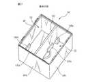
本発明に係る複合型電磁継電器10では、その特徴的構成として、一対の継電器構造体16を互いに逆向き配置で収容する中空箱状の筐体18が、一対の継電器構造体16を袋状に囲繞する囲壁48と、それら継電器構造体16の間に介在して隣り合う継電器構造体16を互いに分離する仕切壁50とを備えて構成される。囲壁48は、平面視略矩形の平板状の頂壁部分48aと、頂壁部分48aの四辺から頂壁部分48aに直交して一体的に延設されるいずれも平板状の二組の対向側壁部分48b、48cとを有し、頂壁部分48aの反対側で対向側壁部分48b、48cの底縁に沿って開口する。平板状の仕切壁50は、囲壁48の頂壁部分48aと一組の対向側壁部分48bとをそれぞれ2等分する位置で、それら頂壁部分48a及び両対向側壁部分48bに直交して一体的に連結され、頂壁部分48aから両対向側壁部分48bの底縁近傍まで延設される。このような構成を有する筐体18は、合成樹脂等の電気絶縁材料から一体に成形できる。 In the composite
筐体18の囲壁48と仕切壁50との間には、互いに実質的同一の略矩形横断面形状を有する一対の収容部52が画定される。一対の継電器構造体16は、前述した逆向き配置でこれら収容部52に個別に収容される。各継電器構造体16を筐体18の対応の収容部52に適正に収容した状態で、継電器構造体16の電磁石装置12の巻枠24は、コイル端子30を支持する図で下方の鍔部24cが、筐体18の開口を実質的に塞ぐように、囲壁48及び仕切壁50の底縁に隣接して配置される。またこの状態で、各継電器構造体16が有するコイル端子対30、第1及び第2の固定接点部材38、46、並びに可動接点ばね部材42は、それぞれの端子部分30b、38c、46c、42eをいずれも筐体18の外部に突出させて配置される。そして、筐体18に適正に収容されたそれら継電器構造体16の巻枠鍔部24cの裏面(露出面)を覆うように、接着剤54が塗着される(図3及び図4)。接着剤54は、筐体18の外側に露出し得る両継電器構造体16と筐体18との間の全ての隙間を封止して、個々の電磁石装置12の巻枠24と囲壁48及び仕切壁50とを互いに固着する。 Between the surrounding
上記構成を有する複合型電磁継電器10においては、互いに独立した一対の継電器構造体16を、共通の筐体18内で、それぞれの接点部14が反対側に位置するように逆向きに配置したから、個々の継電器構造体16に設けられるコイル端子対30が、それぞれの端子部分30bを対同士、互いに離隔した位置で筐体18から突出させて配列される(図1)。同様に、個々の継電器構造体16に設けられる第1及び第2の固定接点部材38、46、並びに可動接点ばね部材42も、それぞれの端子部分38c、46c、42e同士を互いに離隔した位置で筐体18から突出させて配列される。したがって、複合型電磁継電器10の実装基板(図示せず)における回路パターンの形成が容易になる利点が得られる。しかも複合型電磁継電器10では、両継電器構造体16が、個々の電磁石装置12の巻枠24と囲壁48及び仕切壁50とを互いに固着する接着剤54により、筐体18に固定的に支持される構成としたから、一対の継電器構造体を搭載した共通のベースブロックに箱状のカバーを取り付けて筐体を形成する既述の特許文献1の構成に対比して、ベースブロックを排除することができ、その結果、複合型電磁継電器10の高さ方向寸法を縮小できるとともに部品数及び組立工数を削減できる。さらに複合型電磁継電器10では、筐体18の仕切壁50が、互いに並置される一対の継電器構造体16の、特に個々の電磁石装置12における作動要素である接極子22の間に介在するように構成したから、隣り合う継電器構造体16の間に所要の絶縁距離を容易に確保することができる。 In the composite
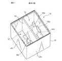
上記した複合型電磁継電器10では、筐体18の囲壁48と仕切壁50との間に画定される一対の収容部52のそれぞれに、個々の継電器構造体16を互いに逆向きの配置に規制するための位置決め要素56(図4及び図5)を有することが有利である。このような位置決め要素56は、筐体18に各継電器構造体16を取り付ける際に、継電器構造体16が適正な方向とは反対の方向に接点部14を向けて収容部52に収容されることを機械的に阻止する誤挿入防止機能を有するものである。図示実施形態では、位置決め要素56は、筐体18の一対の収容部52に、互いに反対の位置関係でそれぞれ突設される少なくとも一組の突起58を含んで構成される。 In the above-described composite
図6〜図9に示すように、筐体18の各収容部52には、囲壁48の頂壁48aに隣接して、一方の側壁部分48bと他方の側壁部分48c及び仕切壁50とのそれぞれの連結領域(隅部分)に、L字形の一対の突起58aが設けられるとともに、側壁部分48c及び仕切壁50上の相互対向位置に、平板形の一対の突起58bが設けられている。これら突起58a、58bは、各収容部52に適正に方向付けして挿入される継電器構造体16に対しては、その構成部品に対して障害となることなく継電器構造体16と囲壁48及び仕切壁50との間の遊休空間を排除する一方で、各収容部52に適正な方向付けとは反対に方向付けして誤挿入される継電器構造体16に対しては、その構成部品に衝突して継電器構造体16の完全な挿入を阻止するような、予め定めた寸法及び形状をそれぞれに有する。したがって、これら突起58a、58bは、組み立てられた複合型電磁継電器10の外力に対する機械的強度を向上させるとともに、内蔵する継電器構造体16のがたつきを防止するようにも作用する。このような突起58a、58bは、例えば筐体18の成形型内で囲壁48及び仕切壁50と共に一体成形することができる。 As shown in FIGS. 6 to 9, each
以上、本発明の好適な実施形態を説明したが、本発明はこれに限定されず、特許請求の範囲に記載した範囲内で様々な変形を施すことができる。例えば、互いに完全に独立した3個以上の継電器構造体を並置して備える複合型電磁継電器にも、本発明に係る複合型電磁継電器の特徴的構成を適用できることは言うまでもない。 As mentioned above, although preferred embodiment of this invention was described, this invention is not limited to this, A various deformation | transformation can be given within the range described in the claim. For example, it goes without saying that the characteristic configuration of the composite electromagnetic relay according to the present invention can also be applied to a composite electromagnetic relay including three or more relay structures that are completely independent of each other.
本発明に係る複合型電磁継電器は、例えばモータやソレノイドを正逆方向に頻繁に切り換えて動作させる制御回路で使用でき、特に、1つの電磁継電器で複数の電動機器類を個々に適時に制御する用途に使用できるものである。また、車載用電動機器類の制御回路のような、狭小な空間に回路構成部品を設置しなければならない用途で有効に使用される。 The composite electromagnetic relay according to the present invention can be used in, for example, a control circuit that frequently switches motors and solenoids in forward and reverse directions to operate. In particular, a single electromagnetic relay controls a plurality of electric devices individually and in a timely manner. It can be used for applications. Further, it is effectively used in applications where circuit components must be installed in a narrow space, such as a control circuit for in-vehicle electric devices.
10…複合型電磁継電器
12…電磁石装置
14…接点部
16…継電器構造体
18…筐体
20…電磁石
22…接極子
24…巻枠
26…コイル
38…第1の固定接点部材
42…可動接点ばね部材
46…第2の固定接点部材
48…囲壁
50…仕切壁
52…収容部
54…接着剤
56…位置決め要素
58…突起DESCRIPTION OF
Claims (3)
Translated fromJapanese前記複数の継電器構造体の前記電磁石装置は、コイル及びコイル端子を支持する巻枠を個別に備え、
前記筐体は、前記複数の継電器構造体を袋状に囲繞する囲壁と、それら継電器構造体の間に介在して隣り合う該継電器構造体を互いに分離する仕切壁とを有し、
前記囲壁は、頂壁部分と、該頂壁部分に直交して一体的に延設される二組の対向側壁部分とを有し、該頂壁部分の反対側で該二組の対向側壁部分の底縁に沿って開口し、
前記仕切壁は、前記頂壁部分及び一組の前記対向側壁部分に直交して一体的に連結され、該頂壁部分から該一組の対向側壁部分の前記底縁の近傍まで延設され、
前記囲壁の前記底縁と前記仕切壁の底縁との間に、前記筐体の複数の開口が画定され、
前記複数の継電器構造体の各々の前記電磁石装置の前記巻枠は、前記コイル端子を支持する鍔部を有し、該複数の継電器構造体の該巻枠の該鍔部が、前記筐体の前記複数の開口を個別に塞ぐように、前記囲壁の前記底縁及び前記仕切壁の前記底縁に隣接して配置され、
前記筐体に収容された前記複数の継電器構造体の各々の前記巻枠の前記鍔部の裏面及び前記仕切壁の前記底縁を覆うように、前記囲壁の前記底縁の内側に接着剤が塗着され、該接着剤により、該筐体の外側に露出し得る該複数の継電器構造体と該筐体との間の隙間が封止されて、個々の該継電器構造体の前記電磁石装置の前記巻枠と前記囲壁及び前記仕切壁とが互いに固着されていること、
を特徴とする複合型電磁継電器。An electromagnet device and a contact portion that opens and closes by the action of the electromagnet device, each having a plurality of relay structures having independent relay structures, and the relay structures alternately on the opposite side In a composite electromagnetic relay comprising a housing that is disposed in a reverse direction so as to be accommodated,
The electromagnet device of the plurality of relay structures includes individually a winding frame that supports a coiland a coil terminal ;
The housing includes a surrounding wall that surrounds the plurality of relay structures in a bag shape, and a partition wall that is interposed between the relay structures and separates adjacent relay structures from each other.
The surrounding wall has a top wall portion and two sets of opposed side wall portions extending integrally perpendicular to the top wall portion, and the two sets of opposed side wall portions on the opposite side of the top wall portion. Open along the bottom edge of the
The partition wall is integrally connected orthogonally to the top wall portion and the set of opposed side wall portions, and extends from the top wall portion to the vicinity of the bottom edge of the set of opposed side wall portions,
A plurality of openings of the housing is defined between the bottom edge of the surrounding wall and the bottom edge of the partition wall,
The winding frame of the electromagnet device of each of the plurality of relay structures has a flange portion that supports the coil terminal, and the flange portions of the winding frames of the plurality of relay structure bodies are connected to the casing. Arranged adjacent to the bottom edge of the surrounding wall and the bottom edge of the partition wall so as to individually block the plurality of openings,
An adhesive is applied to the inside of the bottom edge of the surrounding wall so as to cover the back surface of the flange portion of the winding frame and the bottom edge of the partition wall of each of the plurality of relay structures accommodated in the housing. The gaps between the plurality of relay structures that can be exposed and exposed to the outside of the housing and the housing are sealed by the adhesive, and the electromagnetic devices of theindividual relay structures are sealed . The winding frame, the surrounding wall and the partition wall are fixed to each other;
A composite electromagnetic relay characterized by
The composite electromagnetic relay according to claim 2, wherein the positioning element includes protrusions that protrude from the plurality of housing portions of the housing in a mutually opposite positional relationship.
Priority Applications (2)
| Application Number | Priority Date | Filing Date | Title |
|---|---|---|---|
| JP2003321496AJP4190379B2 (en) | 2003-09-12 | 2003-09-12 | Combined electromagnetic relay |
| US10/936,581US6903638B2 (en) | 2003-09-12 | 2004-09-09 | Complex electromagnetic relay |
Applications Claiming Priority (1)
| Application Number | Priority Date | Filing Date | Title |
|---|---|---|---|
| JP2003321496AJP4190379B2 (en) | 2003-09-12 | 2003-09-12 | Combined electromagnetic relay |
Publications (3)
| Publication Number | Publication Date |
|---|---|
| JP2005093118A JP2005093118A (en) | 2005-04-07 |
| JP2005093118A5 JP2005093118A5 (en) | 2005-06-30 |
| JP4190379B2true JP4190379B2 (en) | 2008-12-03 |
Family
ID=34269952
Family Applications (1)
| Application Number | Title | Priority Date | Filing Date |
|---|---|---|---|
| JP2003321496AExpired - Fee RelatedJP4190379B2 (en) | 2003-09-12 | 2003-09-12 | Combined electromagnetic relay |
Country Status (2)
| Country | Link |
|---|---|
| US (1) | US6903638B2 (en) |
| JP (1) | JP4190379B2 (en) |
Families Citing this family (31)
| Publication number | Priority date | Publication date | Assignee | Title |
|---|---|---|---|---|
| DE102006036613B3 (en)* | 2006-08-04 | 2008-04-10 | Tyco Electronics Austria Gmbh | Relay with a contact arrangement of contact springs |
| JP4735635B2 (en)* | 2007-10-26 | 2011-07-27 | パナソニック電工株式会社 | Electromagnetic relay |
| JP4535138B2 (en)* | 2008-01-25 | 2010-09-01 | パナソニック電工株式会社 | Connected relay unit |
| WO2010150712A1 (en)* | 2009-06-23 | 2010-12-29 | パナソニック電工株式会社 | Electromagnetic relay |
| JP5494042B2 (en)* | 2010-03-12 | 2014-05-14 | オムロン株式会社 | Contact switching structure and electromagnetic relay |
| JP5085754B2 (en)* | 2011-03-14 | 2012-11-28 | オムロン株式会社 | Electromagnetic relay |
| JP4883232B1 (en)* | 2011-03-14 | 2012-02-22 | オムロン株式会社 | Electromagnetic relay |
| EP2688083B1 (en)* | 2011-03-14 | 2019-07-03 | Omron Corporation | Electromagnetic relay |
| JP6025414B2 (en)* | 2011-09-30 | 2016-11-16 | 富士通コンポーネント株式会社 | Electromagnetic relay |
| JP2013196763A (en)* | 2012-03-15 | 2013-09-30 | Omron Corp | Electromagnetic relay |
| SG2012068896A (en)* | 2012-09-17 | 2014-04-28 | Schneider Electric South East Asia Hq Pte Ltd | Tool and method for switching an electromagnetic relay |
| JP6043173B2 (en) | 2012-12-07 | 2016-12-14 | 富士通コンポーネント株式会社 | Electromagnetic relay |
| KR200474510Y1 (en)* | 2013-02-18 | 2014-09-23 | 엘에스산전 주식회사 | Electromagnetic switching device |
| JP6036628B2 (en)* | 2013-09-24 | 2016-11-30 | アンデン株式会社 | Relay module |
| JP6291931B2 (en)* | 2014-03-14 | 2018-03-14 | オムロン株式会社 | Electronic device seal structure and electromagnetic relay using the electronic device seal structure |
| JP6258138B2 (en)* | 2014-07-03 | 2018-01-10 | 富士通コンポーネント株式会社 | Electromagnetic relay |
| JP6422249B2 (en)* | 2014-07-03 | 2018-11-14 | 富士通コンポーネント株式会社 | Electromagnetic relay |
| KR101887316B1 (en)* | 2014-07-23 | 2018-08-09 | 후지쯔 콤포넌트 가부시끼가이샤 | Electromagnetic relay |
| JP6433706B2 (en)* | 2014-07-28 | 2018-12-05 | 富士通コンポーネント株式会社 | Electromagnetic relay and coil terminal |
| JP6459739B2 (en)* | 2015-04-13 | 2019-01-30 | オムロン株式会社 | Terminal connection structure and electromagnetic relay using the same |
| US9754747B1 (en)* | 2016-04-25 | 2017-09-05 | Song Chuan Precision Co., Ltd. | Relay device |
| KR101888275B1 (en)* | 2016-12-23 | 2018-08-14 | 엘에스오토모티브테크놀로지스 주식회사 | Relay device |
| CN107978488B (en)* | 2017-11-27 | 2024-02-02 | 江苏现代电力科技股份有限公司 | Relay |
| JP2020004848A (en)* | 2018-06-28 | 2020-01-09 | 日本電産トーソク株式会社 | Solenoid device |
| JP7204365B2 (en)* | 2018-07-31 | 2023-01-16 | 富士通コンポーネント株式会社 | electromagnetic relay |
| EP3696843B1 (en)* | 2019-02-12 | 2024-05-01 | TE Connectivity Austria GmbH | Housing assembly for encasing an electromagnetic component and a method for assembling a housing |
| DE112020005406T5 (en)* | 2019-11-01 | 2022-08-18 | Xiamen Hongfa Automotive Electronics Co., Ltd. | ELECTROMAGNETIC RELAY |
| JP7067580B2 (en)* | 2020-03-18 | 2022-05-16 | 株式会社デンソーエレクトロニクス | Electromagnetic relay and manufacturing method of electromagnetic relay |
| JP7638633B2 (en)* | 2020-06-30 | 2025-03-04 | Fclコンポーネント株式会社 | Electromagnetic Relay |
| JP7700543B2 (en)* | 2021-07-05 | 2025-07-01 | オムロン株式会社 | electromagnetic relay |
| CN114496658A (en)* | 2022-03-17 | 2022-05-13 | 中创新航科技股份有限公司 | Relays, battery distribution boxes and battery packs |
Family Cites Families (11)
| Publication number | Priority date | Publication date | Assignee | Title |
|---|---|---|---|---|
| US4959627A (en)* | 1987-12-23 | 1990-09-25 | Nec Corporation | Electromagnet relay |
| US5111998A (en)* | 1990-03-30 | 1992-05-12 | Canon Kabushiki Kaisha | Process for producing toner for developing electrostatic image and apparatus system therefor |
| DE69435298D1 (en)* | 1993-11-30 | 2010-08-05 | Canon Kk | Toner and developer for electrostatic images, their production process, and image forming process |
| DE19537612C1 (en)* | 1995-10-09 | 1997-01-09 | Siemens Ag | Electromagnetic relay and process for its manufacture |
| DE19747167C1 (en)* | 1997-10-24 | 1999-04-29 | Siemens Ag | Electromagnetic relay e.g. for high-load currents |
| CN100370364C (en)* | 1998-06-25 | 2008-02-20 | 松下电器产业株式会社 | Toner and method for producing the same |
| JP2000123699A (en) | 1998-10-15 | 2000-04-28 | Matsushita Electric Works Ltd | Electromagnetic relay |
| JP2000315448A (en)* | 1999-05-06 | 2000-11-14 | Omron Corp | Electromagnetic relay |
| US6771154B1 (en)* | 1999-11-12 | 2004-08-03 | Taiko Device, Ltd. | Electromagnetic relay |
| JP2001185015A (en)* | 1999-12-27 | 2001-07-06 | Fujitsu Takamisawa Component Ltd | Multi-connection electromagnetic relay |
| JP3870049B2 (en) | 2001-08-17 | 2007-01-17 | Necトーキン株式会社 | Electromagnetic relay device |
- 2003
- 2003-09-12JPJP2003321496Apatent/JP4190379B2/ennot_activeExpired - Fee Related
- 2004
- 2004-09-09USUS10/936,581patent/US6903638B2/ennot_activeExpired - Fee Related
Also Published As
| Publication number | Publication date |
|---|---|
| US20050057332A1 (en) | 2005-03-17 |
| US6903638B2 (en) | 2005-06-07 |
| JP2005093118A (en) | 2005-04-07 |
Similar Documents
| Publication | Publication Date | Title |
|---|---|---|
| JP4190379B2 (en) | Combined electromagnetic relay | |
| CN100543902C (en) | Electromagnetic relay | |
| CN109727819B (en) | Electromagnetic relay | |
| CN109727818B (en) | Electromagnetic relay | |
| KR100494849B1 (en) | Electromagnetic Relay Apparatus | |
| JP5566172B2 (en) | Electromagnetic relay | |
| JP2019083173A (en) | Magnetic relay | |
| US11043347B2 (en) | Electromagnetic relay | |
| JP2019083174A (en) | Electromagnetic relay | |
| US10403460B2 (en) | Electromagnetic relay | |
| JP4212248B2 (en) | Electromagnetic relay | |
| JP4307182B2 (en) | Electromagnetic relay | |
| US4730176A (en) | Electromagnet having a pivoted polarized armature | |
| JP2005222946A (en) | Electromagnetic relay and receptacle | |
| US10943751B2 (en) | Electromagnetic relay | |
| US7498912B2 (en) | Electromagnetic relay | |
| JP2004127581A (en) | Electromagnetic relay | |
| JP4274881B2 (en) | Electromagnetic relay | |
| JPS6222056Y2 (en) | ||
| JPH0718117Y2 (en) | Electromagnetic relay | |
| JPH0515701Y2 (en) | ||
| JP2021057223A (en) | relay | |
| JP2003031096A (en) | Electromagnetic relay | |
| JPH08235991A (en) | Electromagnetic relay | |
| JPH1196878A (en) | Electromagnetic relay |
Legal Events
| Date | Code | Title | Description |
|---|---|---|---|
| A621 | Written request for application examination | Free format text:JAPANESE INTERMEDIATE CODE: A621 Effective date:20060615 | |
| A977 | Report on retrieval | Free format text:JAPANESE INTERMEDIATE CODE: A971007 Effective date:20080401 | |
| A131 | Notification of reasons for refusal | Free format text:JAPANESE INTERMEDIATE CODE: A131 Effective date:20080422 | |
| A521 | Request for written amendment filed | Free format text:JAPANESE INTERMEDIATE CODE: A523 Effective date:20080623 | |
| TRDD | Decision of grant or rejection written | ||
| A01 | Written decision to grant a patent or to grant a registration (utility model) | Free format text:JAPANESE INTERMEDIATE CODE: A01 Effective date:20080819 | |
| A01 | Written decision to grant a patent or to grant a registration (utility model) | Free format text:JAPANESE INTERMEDIATE CODE: A01 | |
| A61 | First payment of annual fees (during grant procedure) | Free format text:JAPANESE INTERMEDIATE CODE: A61 Effective date:20080916 | |
| FPAY | Renewal fee payment (event date is renewal date of database) | Free format text:PAYMENT UNTIL: 20110926 Year of fee payment:3 | |
| R150 | Certificate of patent or registration of utility model | Free format text:JAPANESE INTERMEDIATE CODE: R150 | |
| FPAY | Renewal fee payment (event date is renewal date of database) | Free format text:PAYMENT UNTIL: 20120926 Year of fee payment:4 | |
| FPAY | Renewal fee payment (event date is renewal date of database) | Free format text:PAYMENT UNTIL: 20130926 Year of fee payment:5 | |
| R250 | Receipt of annual fees | Free format text:JAPANESE INTERMEDIATE CODE: R250 | |
| R250 | Receipt of annual fees | Free format text:JAPANESE INTERMEDIATE CODE: R250 | |
| S531 | Written request for registration of change of domicile | Free format text:JAPANESE INTERMEDIATE CODE: R313531 | |
| R350 | Written notification of registration of transfer | Free format text:JAPANESE INTERMEDIATE CODE: R350 | |
| LAPS | Cancellation because of no payment of annual fees |