JP4188981B2 - Nickel metal hydride storage battery charging method and charging apparatus for executing the charging method - Google Patents
Nickel metal hydride storage battery charging method and charging apparatus for executing the charging methodDownload PDFInfo
- Publication number
- JP4188981B2 JP4188981B2JP2006159965AJP2006159965AJP4188981B2JP 4188981 B2JP4188981 B2JP 4188981B2JP 2006159965 AJP2006159965 AJP 2006159965AJP 2006159965 AJP2006159965 AJP 2006159965AJP 4188981 B2JP4188981 B2JP 4188981B2
- Authority
- JP
- Japan
- Prior art keywords
- storage battery
- charging
- temperature
- current
- metal hydride
- Prior art date
- Legal status (The legal status is an assumption and is not a legal conclusion. Google has not performed a legal analysis and makes no representation as to the accuracy of the status listed.)
- Expired - Fee Related
Links
Images


Classifications
- Y—GENERAL TAGGING OF NEW TECHNOLOGICAL DEVELOPMENTS; GENERAL TAGGING OF CROSS-SECTIONAL TECHNOLOGIES SPANNING OVER SEVERAL SECTIONS OF THE IPC; TECHNICAL SUBJECTS COVERED BY FORMER USPC CROSS-REFERENCE ART COLLECTIONS [XRACs] AND DIGESTS
- Y02—TECHNOLOGIES OR APPLICATIONS FOR MITIGATION OR ADAPTATION AGAINST CLIMATE CHANGE
- Y02E—REDUCTION OF GREENHOUSE GAS [GHG] EMISSIONS, RELATED TO ENERGY GENERATION, TRANSMISSION OR DISTRIBUTION
- Y02E60/00—Enabling technologies; Technologies with a potential or indirect contribution to GHG emissions mitigation
- Y02E60/10—Energy storage using batteries
Landscapes
- Secondary Cells (AREA)
- Charge And Discharge Circuits For Batteries Or The Like (AREA)
Description
Translated fromJapanese本発明は、ニッケル水素蓄電池の充電方法および該充電方法を実行する充電装置に関する。 The present invention relates to a method for charging a nickel metal hydride storage battery and a charging device for executing the method.
ニッケル水素蓄電池は一般に定電流充電法によって充電される。電流値は0.1C以上が普通であり、最近では15分で満充電にできるようなニッケル水素蓄電池も開発されている。これに対して一般に0.05C未満の低電流でニッケル水素蓄電池を充電すると充電効率は低くなり、また劣化を早めることになるので、通常このような低電流での充電は行われない。太陽電池や風力発電機の出力を大規模にニッケル水素蓄電池に蓄電する場合には、大容量の蓄電池が必要になるが、充電電流もそのために大きな値が必要になる。ところが太陽光発電や風力発電のような自然エネルギーを利用した発電では、出力は日照量や風速によって時間と共に大きく変動するのが普通である。そこで、出力電流を直接蓄電池に接続して充電すると電流値が小さ過ぎる場合には、一旦コンデンサ等に充電し、十分充電した段階で大電流パルスとして出力するニッケル水素蓄電池の充電方法が発案されている(非特許文献1参照)。
しかしながら、上記のニッケル水素蓄電池の充電方法では、コンデンサ等に充電し、十分充電した段階で大電流パルスとして出力するため、充電回路にコンデンサ等の充電器および大電流パルスを発生させるパルス発生器が必要となり、充電回路が複雑かつ高価になるといった問題があった。 However, in the above charging method of the nickel metal hydride storage battery, a capacitor or the like is charged and output as a large current pulse when fully charged. Therefore, a charger such as a capacitor and a pulse generator for generating a large current pulse are provided in the charging circuit. There is a problem that the charging circuit becomes complicated and expensive.
また、大電流パルスによる充電を避けつつ、低電流でニッケル水素蓄電池を充電しても、ニッケル水素蓄電池の充電効率を低下させず、劣化を防止する方法として、小容量のニッケル水素蓄電池を多数並列にして組み合わせた充電回路も発案されている。しかし、この場合も、太陽光発電や風力発電のような自然エネルギーを利用した発電による出力が大きく変動する点は同じであり、各ニッケル水素蓄電池に流す電流の分配などの充電制御は複雑になるといった問題もあった。 In addition, avoiding charging by large current pulses and charging nickel-metal hydride storage batteries at low currents does not reduce the charging efficiency of nickel-metal hydride storage batteries, and as a method to prevent deterioration, many small-capacity nickel-metal hydride storage batteries are connected in parallel. A combined charging circuit has also been proposed. However, in this case as well, the output from power generation using natural energy such as solar power generation and wind power generation fluctuates greatly, and charging control such as distribution of current flowing to each nickel metal hydride storage battery is complicated. There was also a problem.
本発明は、こうした問題に鑑みてなされたものであり、充電効率の低下を防止しつつ、安価で簡易な回路を用いて、直流電流源から直接充電できるニッケル水素蓄電池の充電方法および該充電方法を実行する充電装置を提供することを目的とする。 The present invention has been made in view of such problems, and a charging method for a nickel-metal hydride storage battery that can be directly charged from a direct current source using an inexpensive and simple circuit while preventing a decrease in charging efficiency, and the charging method It aims at providing the charging device which performs.
上記目的達成のため、本発明に係るニッケル水素蓄電池の充電方法では、ニッケル水素蓄電池またはニッケル水素蓄電池複数セルからなる蓄電池モジュールを直流電流源に接続して充電する充電方法において、充電対象のニッケル水素蓄電池または蓄電池モジュールの充電時の上限温度および下限温度と、充電電流の下限値と、充電終了電圧を予め定め、充電中、充電対象のニッケル水素蓄電池または蓄電池モジュールの蓄電池温度および蓄電池電圧と、前記直流電流源から得られる充電電流とを計測し、前記蓄電池温度が前記上限温度と前記下限温度の間にあり、かつ前記充電電流の電流値が前記下限値を上回っており、かつ前記蓄電池電圧が前記充電終了電圧を下回っている限り、充電を継続し、前記充電電流の電流値が前記下限値以下に低下した場合には充電を停止することを特徴としている。In order to achieve the above object, in a method for charging a nickel metal hydride storage battery according to the present invention, a nickel metal hydride storage battery or a battery module comprising a plurality of nickel metal hydride storage batteries is connected to a direct current source for charging. The upper limit temperature and lower limit temperature at the time of charging the storage battery or storage battery module, the lower limit value of the charging current, and the charging end voltage are determined in advance, and during charging, the storage battery temperature and storage battery voltage of the nickel hydride storage battery or storage battery module to be charged, A charging current obtained from a direct current source is measured, the storage battery temperature is between the upper limit temperature and the lower limit temperature, the current value of the charging current exceeds the lower limit value, and the storage battery voltage is As long as below the charging end voltage,to continue thecharging current value of the charging current is less than the lower limit value It is characterized bystopping the charging when lowered.
また、請求項2に記載のように、請求項1に記載のニッケル水素蓄電池の充電方法では、前記充電対象のニッケル水素蓄電池または蓄電池モジュールと同種のニッケル水素蓄電池または蓄電池モジュールについて、環境温度25℃で0.1C以上の定電流値で充電した後、25℃、30Aで放電して計測した容量を基準容量として、環境温度25℃で0.05Cを上回らない電流値で充電した後、25℃、30Aで放電して計測した容量と前記基準容量との割合が95%以上となる前記電流値を、前記蓄電池温度25℃以下における前記下限値とし、環境温度45℃で0.05Cを上回らない電流値で充電した後、25℃、30Aで放電して計測した容量と前記基準容量との割合が80%以上となる前記電流値を、前記蓄電池温度45℃以上における前記下限値とすることを特徴としている。 Further, as described in
また、請求項3に記載のように、請求項1または2に記載のニッケル水素蓄電池の充電方法では、設定温度TLとTH(TL<TH)を定め、前記蓄電池温度が前記設定温度TL未満である場合、前記下限値を一定値ILとし、前記蓄電池温度が前記設定温度TH以上である場合、前記下限値を一定値IH(IL<IH)とし、前記蓄電池温度が設定温度TL以上、TH未満の場合、前記下限値I0を、前記充電電流をI、前記蓄電池温度をTとした場合に、
I0=((IH−IL)/(TH−TL))×(T−TH)+IH
で表される関係式から算出した値とすることを特徴としている。Further, as described in
I0 = ((IH−IL) / (TH−TL)) × (T−TH) + IH
The value is calculated from the relational expression expressed by
また、請求項4に記載のように、請求項1乃至3のいずれかに記載のニッケル水素蓄電池の充電方法では、前記充電対象のニッケル水素蓄電池または蓄電池モジュールと同種のニッケル水素蓄電池または蓄電池モジュールについて、充電終了時電圧、充電終了時温度および充電電流を予め計測し、前記充電終了時電圧、前記充電終了時温度および前記充電電流の計測結果から、前記充電終了電圧、前記蓄電池温度および前記充電電流の関係を導出し、前記蓄電池温度、前記充電電流および前記関係から、前記充電終了電圧を算出することを特徴としている。 In addition, as described in
また、請求項5に記載のように、請求項4に記載のニッケル水素蓄電池の充電方法では、前記充電電流をI、前記蓄電池温度をT、前記充電終了電圧をV、ニッケル水素蓄電池の内部抵抗をR0、前記充電電流を一定にして予め計測した前記充電終了時電圧および前記充電終了時温度から算出した基準電圧をV0、ニッケル水素蓄電池によって定まる正の定数をa、bとすると、前記関係は、
V=V0−aT+I(R0−bT)と表されることを特徴としている。Further, as described in
V = V0−aT + I (R0−bT).
また、請求項6に記載のように、請求項4に記載のニッケル水素蓄電池の充電方法では、前記充電電流をI、前記蓄電池温度をT、前記充電終了電圧をV、前記充電電流を一定にして予め計測した前記充電終了時電圧および前記充電終了時温度から算出した基準電圧をV0、ニッケル水素蓄電池によって定まる正の定数をc、eとすると、前記関係は、V=V0−cT+eIと表されることを特徴としている。 Further, as described in claim 6, in the method for charging a nickel metal hydride storage battery according to
また、請求項7に記載のように、請求項1乃至6のいずれかに記載のニッケル水素蓄電池の充電方法では、前記直流電流源は、自然エネルギーを利用して発電した電源であることを特徴としている。 In addition, as described in claim 7, in the method for charging a nickel metal hydride storage battery according to any one of
また、請求項8に記載のように、請求項1乃至7のいずれかに記載のニッケル水素蓄電池の充電方法を実行する充電装置であって、前記ニッケル水素蓄電池または前記蓄電池モジュールを充電する前記直流電流源と、前記ニッケル水素蓄電池または前記蓄電池モジュールと前記直流電流源との間の電路を開閉する開閉手段と、前記蓄電池温度を検出する温度検出手段と、前記充電電流を検出する電流検出手段と、前記蓄電池電圧を検出する電圧検出手段と、前記蓄電池温度、前記充電電流および前記蓄電池電圧から前記開閉手段を制御する制御手段としている。 Moreover, it is a charging apparatus which performs the charging method of the nickel hydride storage battery in any one of
本発明により、自然エネルギーを利用した直流電流源からニッケル水素蓄電池を充電する場合において、充電効率の低下を防止しつつ、安価で簡易な回路を用いて、直接充電可能なニッケル水素蓄電池の充電方法および該充電方法を実行する充電装置を提供することができる。 According to the present invention, when charging a nickel metal hydride storage battery from a direct current source utilizing natural energy, a method for charging a nickel metal hydride storage battery that can be directly charged using an inexpensive and simple circuit while preventing a decrease in charging efficiency. And the charging device which performs this charging method can be provided.
本発明に係るニッケル水素蓄電池の充電方法および該充電方法を実行する充電装置について、公称容量95Ahのバックアップ用ニッケル水素蓄電池を10セル直列に接続した蓄電池モジュール10を充電する太陽電池6を備える充電装置100を例として説明する。 About the charging method of the nickel hydride storage battery which concerns on this invention, and the charging device which performs this charging method, a charging device provided with the solar cell 6 which charges the
(第1の実施形態)
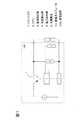
第1の実施形態の充電方法を実行する充電装置100を、図1を参照して説明する。図1は本発明に係る第1の実施形態の充電方法を実行する充電装置100を示す概略図である。図1に示す充電装置100は、蓄電池モジュール10を充電する直流電流源である90Wの太陽電池6と、蓄電池モジュール10と太陽電池6とを直接接続する電路を開閉する開閉手段であるトランジスタ1と、蓄電池モジュール10の蓄電池温度Tを検出する温度検出手段である温度検出器4と、充電電流Iを検出する電流検出手段である電流検出器3と、蓄電池電圧V1を検出する電圧検出手段である電圧検出器5と、蓄電池温度T、充電電流Iおよび蓄電池電圧V1からトランジスタ1を開閉制御する制御手段であるCPU2とを備えている。(First embodiment)
A
ここで、第1の実施形態のニッケル水素蓄電池の充電方法について説明する。当該充電方法では、充電対象の蓄電池モジュール10における充電時の上限温度TAと、下限温度TBと、充電電流Iの下限値I0と、充電終了電圧Vを予め設定する。次に、充電装置100で蓄電池モジュール10の充電を開始する。充電装置100では、蓄電池モジュール10の充電中、蓄電池温度T、蓄電池電圧V1と、太陽電池6から得られる充電電流Iとを計測している。蓄電池モジュール10の蓄電池温度Tが、上記設定しておいた上限温度TAと下限温度TBの間にあり、かつ充電電流Iの電流値が下限値I0を上回っており、かつ蓄電池電圧V1が充電終了電圧Vを下回っている限りにおいて充電を継続する。すなわち、CUP2はトランジスタ1のON状態を継続する。一方、蓄電池温度Tが上限温度TAを超過したり、下限温度TBより低下したり、充電電流Iの電流値が下限値I0以下に低下したり、蓄電池電圧V1が充電終了電圧V以上になった場合、CPU2は充電を終了する。すなわち、CPU2はトランジスタ1をOFFにする。 Here, a method for charging the nickel-metal hydride storage battery of the first embodiment will be described. In the charging method, an upper limit temperature TA, a lower limit temperature TB, a lower limit value I0 of the charging current I, and a charge end voltage V are set in advance in the
次に、上記の充電電流Iの下限値I0について説明する。第1の実施形態の下限値I0は、設定温度TLおよびTH(TL<TH)で区切られた3個の範囲、すなわち、設定温度TL未満の範囲、設定温度TL以上、TH未満の範囲および設定温度TH以上の範囲において、変化する変数である。蓄電池温度Tが設定温度TL未満の場合、下限値I0は一定値ILに設定される。蓄電池温度Tが設定温度TH以上の場合、下限値I0は一定値IHに設定される。一方、蓄電池温度Tが設定温度TL以上、TH未満の場合、下限値I0は、
I0=((IH−IL)/(TH−TL))×(T−TH)+IH (数1)
で表される関係式から算出した値に設定される。Next, the lower limit value I0 of the charging current I will be described. The lower limit I0 of the first embodiment has three ranges divided by a set temperature TL and TH (TL <TH), that is, a range below the set temperature TL, a range above the set temperature TL, and below the TH. It is a variable that changes in the range above the temperature TH. When storage battery temperature T is lower than set temperature TL, lower limit value I0 is set to a constant value IL. When storage battery temperature T is equal to or higher than set temperature TH, lower limit value I0 is set to a constant value IH. On the other hand, when the storage battery temperature T is equal to or higher than the set temperature TL and lower than TH, the lower limit value I0 is
I0 = ((IH−IL) / (TH−TL)) × (T−TH) + IH (Equation 1)
Is set to a value calculated from the relational expression expressed by
そして、蓄電池モジュール10と同種の蓄電池モジュールについて、充電時の環境温度および充電電流Iを変化させて、各条件における容量を計測して、充電効率が大幅に低下しない値に、設定温度TL、THおよび一定値IL、IHを決定する。第1の実施形態では、蓄電池モジュール10と同種の蓄電池モジュールを定電流充放電装置(不図示)に接続し、蓄電池モジュールを30Aの電流で10Vまで放電させた後、環境温度25℃、充電電流10Aで11時間充電した。その後再び、25℃、30Aの電流で10Vまで放電させて容量(基準容量)を計測したところ、94、13Ahであった。また、当該蓄電池モジュールを充電電流1Aで110時間充電した後、25℃、30Aで放電した。放電時に計測した蓄電池モジュールの容量は、充電時の環境温度が25℃の場合、93.14Ahであった。また、35℃の場合、87.87Ahであった。更に、45℃の場合、75.39Ahであった。また、充電時の環境温度を45℃とし、充電電流2Aで、55時間充電した後、同様に容量を計測すると、86.5Ahであった。以上の結果から、このバックアップ用蓄電池モジュールでは、25℃、10Aで11時間充電した場合の基準容量(94、13Ah)に対する、25℃、1Aで110時間充電した場合の容量(93.14Ah)の割合は98.9%であった。また、45℃、1Aで110時間充電した場合の容量(75.39Ah)の割合は80.1%であった。更に、45℃、2Aで55時間充電した場合の容量(86.5Ah)の割合は91.9%であった。従って、充電電流1〜2A程度であっても十分充電が可能であることがわかった。そこで、高温での充電電流Iの一定値IHを2.0Aとし、低温での充電電流Iの一定値ILを0.5Aとした。 And about the storage battery module of the same kind as the
次に、上記の充電終了電圧Vについて説明する。一般に、ニッケル水素蓄電池は、高温になるに連れて充電受け入れ性が低下し、同一電流値で充電しても放電容量が小さくなる傾向がある。そこで、蓄電池モジュール10と同種の蓄電池モジュールを25℃、30Aで10.0Vまで放電した後、25℃、20Aで充電し、dT/dt=0.3℃/分で充電停止後、更に3Aで2時間充電した。その後、もう一度30Aで10.0Vまで放電させて、蓄電池モジュールの容量を計測した。上記の容量は、93.8Ahであった。次に、蓄電池モジュールを45℃で同一充電条件で充電し、容量を計測した。このときの容量は90.5Ahであった。これから、45℃においても高い充電受け入れ性が確認できた。 Next, the charging end voltage V will be described. In general, nickel-metal hydride storage batteries have lower charge acceptability as the temperature rises, and the discharge capacity tends to decrease even when charged with the same current value. Therefore, after discharging a storage battery module of the same type as the
図2は、蓄電池モジュールを20Aで充電した時の充電終了時温度と充電終了時電圧の関係を示す図である。図2では、充電時の環境温度を0℃から45℃で変化させて、充電電流Iを20Aとして充電したときの蓄電池モジュール10と同種の蓄電池モジュールの充電終了時温度と充電終了時電圧の関係を示している。この結果から、充電電流Iが一定の場合、充電終了時電圧は、蓄電池モジュールの充電終了時温度の一次式で高精度に近似できることがわかる。 FIG. 2 is a diagram illustrating the relationship between the charging end temperature and the charging end voltage when the storage battery module is charged with 20A. In FIG. 2, the relationship between the charging end temperature and the charging end voltage of the storage battery module of the same type as the
図3は、蓄電池モジュールを45℃で充電した時の充電電流Iと充電終了時電圧との関係を示す図である。図3では、充電時環境温度を45℃に保って、充電電流Iを1Aから20Aまで変えて充電した場合の蓄電池モジュール10と同種の蓄電池モジュールにおける充電電流Iと充電終了時電圧との関係を示している。充電電流Iが小さい領域(0<I<3A)では、蓄電池モジュールの充電時の温度上昇が小さいため、蓄電池モジュールの充電終了時温度は一定と見なすことができる。これから、充電電流Iが小さい領域(0<I<3A)では、充電終了時電圧に対する充電電流Iの依存性は一次式で精度よく近似できることがわかる。図2および図3の結果を1つの式にまとめると、ニッケル水素蓄電池の起電力および内部抵抗R0の温度依存性を、蓄電池モジュールの蓄電池温度Tの一次式で近似することで、充電終了電圧V、蓄電池温度Tおよび充電電流Iの関係を、
V=V0−aT+I(R0−bT) (数2)
と表せる。ここで、V0は、充電電流Iを一定にして、予め計測した充電終了時電圧および充電終了時温度から算出した基準電圧であり、定数aおよびbは、ニッケル水素蓄電池によって定まる正の定数である。定数aおよびbは、予め計測した充電終了時電圧、充電電流I、充電終了時温度、ニッケル水素蓄電池の内部抵抗R0および上記算出した基準電圧V0から算出する。FIG. 3 is a diagram showing the relationship between the charging current I when the storage battery module is charged at 45 ° C. and the voltage at the end of charging. In FIG. 3, the relationship between the charging current I and the voltage at the end of charging in the
V = V0−aT + I (R0−bT) (Expression 2)
It can be expressed. Here, V0 is a reference voltage calculated from the charging end voltage and the charging end temperature measured in advance with the charging current I constant, and the constants a and b are positive constants determined by the nickel metal hydride storage battery. . The constants a and b are calculated from the charging end voltage, the charging current I, the charging end temperature, the internal resistance R0 of the nickel metal hydride storage battery, and the above calculated reference voltage V0.
更に、蓄電池モジュール10の同種の蓄電池モジュールを太陽電池6に接続し、充電を行った。各蓄電池温度Tでの充電電流Iの下限値I0は、蓄電池温度T≦30℃で0.5A、30℃<T≦37.5℃で1.0A、37.5℃<T≦45.0℃で1.5A、T>45℃で2.0Aとした。充電終了電圧Vは、(数2)において、基準電圧V0=15.0V、ニッケル水素蓄電池の内部抵抗R0=0.05Ω、定数a=0,030V/℃、定数b=0.0003Ω/℃として算出した。屋外で5日間充電したところ、蓄電池電圧V1が充電終了電圧Vに達して充電が停止した。充電時の平均電流は2.5Aであった。その後放電電流30Aで容量を計測したところ、86.8Ahであった。次に、充電電流Iの下限値I0を(数1)によって定め、設定温度TL=25℃、設定温度TH=40℃、一定値IL=0.5A、一定値IH=2.0Aとした。この条件で、基準電圧V0=15.0V、ニッケル水素蓄電池の内部抵抗R0=0.05Ω、定数a=0,030V/℃、定数b=0.0003Ω/℃で算出した充電終了電圧Vまで充電したところ、6日間で蓄電池電圧V1が充電終了電圧Vに達した。平均充電電流は2.2Aであった。その後容量を計測したところ88.2Ahであった。これから、蓄電池モジュール10の充電の際、設定温度TL=25℃、設定温度TH=40℃、一定値IL=0.5A、一定値IH=2.0A、基準電圧V0=15.0V、ニッケル水素蓄電池の内部抵抗R0=0.05Ω、定数a=0,030V/℃、定数b=0.0003Ω/℃に設定する。また、充電時の上限温度TAおよび下限温度TBも設定する。 Furthermore, the storage battery module of the same kind of the
次に、蓄電池モジュール10の充電における各制御処理について説明する。第1の実施形態では、目標値超過の容量で充電可能な充電電流Iおよび環境温度を求める制御処理を実行しつつ、基準電圧V0および定数a、bを算出する制御処理を実行している。その後、蓄電池モジュール10の充電を自動終了させる制御処理を実行している。 Next, each control process in charge of the
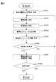
図4は、目標値超過の割合で充電可能な充電電流Iおよび環境温度を求める制御処理を示すフローチャートである。第1の実施形態では、上述したように、蓄電池モジュール10と同種の蓄電池モジュールを定電流充放電装置(不図示)に接続し、環境温度25℃、充電電流10Aでの充放電における基準容量に対するある環境温度、ある充電電流Iでの充放電における容量の割合が目標値を超過するように、蓄電池モジュールを充電できる条件(環境温度および充電電流I)を求めている。図4に示す制御処理では、まず、蓄電池モジュール10と同種の蓄電池モジュールを環境温度25℃、充電電流10Aで11時間充電した後、25℃、30Aの電流で10Vまで放電させて計測した基準容量をユーザに設定させる(ステップS101)。更に、ある環境温度、ある充電電流Iでの充放電における容量の基準容量に対する割合の目標値を当該環境温度ごとにユーザに設定させる(ステップS101)。なお、第1の実施形態では、当該目標値を、環境温度25℃で95%以上、環境温度45℃で80%以上としている。ここで、当該目標値は、蓄電池モジュールの充電効率が大幅に低下しない値とする。 FIG. 4 is a flowchart showing a control process for obtaining the charging current I and the environmental temperature that can be charged at a rate exceeding the target value. In the first embodiment, as described above, a storage battery module of the same type as the
次に、環境温度および充電電流Iをユーザに設定させる(ステップS102およびS103)。上記で設定させた環境温度および充電電流Iで蓄電池モジュールを充電した後、放電し(ステップS104)、蓄電池モジュールの容量を計測する(ステップS105)。上記計測された容量と設定された基準容量とから、基準容量に対する上記計測された容量の割合を計算する。次に、当該計算値と設定された目標値とを比較する(ステップS106)。計算値が目標値以下の場合(ステップS106、No)、ユーザに報知すると共に、ステップS102に戻り、ステップS102〜S106の一連の制御処理を繰り返し実行する。一方、計算値が目標値を超過していた場合(ステップS106、Yes)、ユーザに報知すると共に、環境温度および充電電流Iを格納する(ステップS107)。次に、ユーザに、格納した環境温度および充電電流Iを目安として、設定温度TL、THおよび一定値IL、IHを設定できるか否か確認する(ステップS109)。ユーザが設定できないと判断した場合(ステップS108、No)、ステップS102に戻り、ステップS102〜S106の一連の制御処理を繰り返し実行する。一方、ユーザが設定できると判断した場合(ステップS108、Yes)、本制御処理を終了する。これにより、格納した環境温度および充電電流Iを目安として、上記計算値が目標値以下にならない値、すなわち、充電効率が大幅に低下しない値に、設定温度TL、THおよび一定値IL、IHを容易に設定することができる。よって、蓄電池モジュール10の充電において、充電効率の低下を防止できる。 Next, the user sets the environmental temperature and the charging current I (steps S102 and S103). After charging the storage battery module with the environmental temperature and the charging current I set as described above, the storage battery module is discharged (step S104), and the capacity of the storage battery module is measured (step S105). From the measured capacity and the set reference capacity, the ratio of the measured capacity to the reference capacity is calculated. Next, the calculated value is compared with the set target value (step S106). When the calculated value is equal to or less than the target value (No at Step S106), the user is notified and the process returns to Step S102 to repeatedly execute a series of control processes at Steps S102 to S106. On the other hand, when the calculated value exceeds the target value (step S106, Yes), the user is notified and the environmental temperature and the charging current I are stored (step S107). Next, it is confirmed to the user whether or not the set temperatures TL and TH and the constant values IL and IH can be set using the stored environmental temperature and charging current I as a guide (step S109). When it is determined that the user cannot be set (No at Step S108), the process returns to Step S102, and a series of control processes at Steps S102 to S106 are repeatedly executed. On the other hand, when it is determined that the user can set (step S108, Yes), this control process ends. As a result, using the stored ambient temperature and charging current I as a guide, the set temperatures TL and TH and the constant values IL and IH are set to values that do not cause the calculated value to fall below the target value, that is, values that do not significantly reduce charging efficiency. It can be set easily. Therefore, in charging of the
図5は、基準電圧V0および定数a、bを算出する制御処理を示すフローチャートである。上述したように、蓄電池モジュール10と同種の蓄電池モジュールにおける充電終了時電圧および充電終了時温度を計測し、基準電圧V0および定数a、bを求めている。図5に示す制御処理では、まず、蓄電池モジュール10と同種の蓄電池モジュールの内部抵抗R0をユーザに設定させ(ステップS201)、充電電流Iをユーザに設定させる(ステップS202)。次に、環境温度をユーザに設定させ(ステップS203)、蓄電池モジュールを充電電流Iで充電する(ステップS204)。充電終了後、充電終了時電圧および充電終了時温度を計測する(ステップS205)。上述のように、充電電流Iが一定の場合、充電終了時電圧は蓄電池モジュールの充電終了時温度の一次式で高精度に近似できる。次に、基準電圧V0および定数a、bを算出できるか否か確認する(ステップS206)。基準電圧V0および定数a、bを算出できる程、充電終了時電圧と充電終了時温度を十分に計測していない場合は(ステップS206、No)、ステップS203に戻り、ステップS203〜S206の一連の制御処理を実行する。一方、基準電圧V0および定数a、bを算出できる程、充電終了時電圧と充電終了時温度を多数、高精度で計測していた場合(ステップS206、Yes)、基準電圧V0を算出する(ステップS207)。例えば、充電終了時温度0℃における充電終了時電圧、充電電流Iおよび内部抵抗R0を(数2)に代入して基準電圧V0を算出する。次に、算出した基準電圧V0を用いて、定数a、bを算出し(ステップS208)、本制御処理を終了する。 FIG. 5 is a flowchart showing a control process for calculating the reference voltage V0 and the constants a and b. As described above, the charging end voltage and the charging end temperature in the storage battery module of the same type as the
図6は、図1に示すCPU2の内部構成を示すブロック図である。CPU2は、各設定値をユーザに設定させるとともに、充電終了を知らせるGUI21と、GUI21により設定された各設定値を格納し、(数1)および(数2)を格納する記憶手段22と、電流検出器3、温度検出器4および電圧検出器5からの各検出信号、すなわち、充電電流I、蓄電池温度Tおよび蓄電池電圧V1の送受信の際にタイミングの制御等するI/F26と、各検出信号および各設定値から下限値I0および充電終了電圧Vを算出する演算手段24と、蓄電池温度Tと上限温度TAおよび下限温度TBを比較し、充電電流Iと下限値I0とを比較し、蓄電池電圧V1と充電終了電圧Vとを比較する比較手段25と、各制御手段で必要となるデータの出入力の制御処理を取扱う主制御手段23とから構成されている。 FIG. 6 is a block diagram showing an internal configuration of the
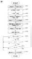
図7は、蓄電池モジュール10の充電を自動終了させる制御処理を示すフローチャートである。まず、GUI21は、上限温度TA、下限温度TBをユーザに設定させる(ステップS301)。更に、設定温度TL、THおよび一定値IL、IHを設定させる(ステップS302およびS303)。ここで、ユーザは、設定温度TL、THおよび一定値IL、IHの設定の際、図4に示した制御処理で格納した環境温度および充電電流Iを用いることもできる。第1の実施形態では、格納した環境温度および充電電流Iを目安として、設定温度TLおよび一定値IL、IHを充電効率が大幅に低下しない値に設定し、蓄電池モジュール10の充電において、充電効率の低下を防止している。次に、GUI21は、ニッケル水素蓄電池の内部抵抗R0、基準電圧V0、定数a、bをユーザに設定させる(ステップS304)。基準電圧V0および定数a、bは、図5に示した制御処理において、すでに算出されているので、ユーザは、算出された各値に設定すればよい。第1の実施形態では、上述のように、設定温度TL=25℃、設定温度TH=40℃、一定値IL=0.5A、一定値IH=2.0A、基準電圧V0=15.0V、ニッケル水素蓄電池の内部抵抗R0=0.05Ω、定数a=0,030V/℃、定数b=0.0003Ω/℃とした。そして、主制御手段23は、上記設定値を記憶手段21に格納する。また、記憶手段21には、(数1)および(数2)も格納されている。 FIG. 7 is a flowchart showing a control process for automatically terminating the charging of the
次に、蓄電池モジュール10の充電を開始する(ステップS305)。すなわち、主制御手段23はトランジスタ1をONにする。次に、電流検出器3、温度検出器4および電圧検出器5は充電電流I、蓄電池温度Tおよび蓄電池電圧V1の計測を開始する(ステップS306)。更に、主制御手段23は、I/F26を介して、充電電流I、蓄電池温度Tおよび蓄電池電圧V1を取得し、記憶手段23に格納する。次に、演算手段24は、記憶手段21に格納された(数1)、蓄電池温度T、設定温度TL、TH、一定値ILおよびIHに基づいて、充電電流Iの下限値I0を算出する(ステップS307)。更に、演算手段24は、記憶手段21に格納された(数2)、充電電流I、蓄電池温度T、ニッケル水素蓄電池の内部抵抗R0、基準電圧V0、定数aおよびbに基づいて、充電終了電圧Vを算出する(ステップS308)。次に、記憶手段21に格納された上限温度TA、下限温度TB、蓄電池温度Tに基づいて、比較手段25は蓄電池温度Tが上限温度TA、下限温度TBの間にあるか否か判定する(ステップS309)。比較手段25によって、蓄電池温度Tが上限温度TA、下限温度TBの間にないと判定された場合(ステップS309、No)、主制御手段23は蓄電池モジュール10の充電を終了する(ステップS312)。すなわち、主制御手段23はトランジスタ1をOFFにする。これより、本制御処理を終了する。 Next, charging of the
一方、比較手段25によって、蓄電池温度Tが上限温度TA、下限温度TBの間にあると判定された場合(ステップS309、Yes)、比較手段25は、演算手段24で算出された下限値I0を充電電流Iが上回っているか判定する(ステップS310)。充電電流Iが下限値I0を上回っていない場合(ステップS310、No)、主制御手段23は蓄電池モジュール10の充電を終了する(ステップS312)。一方、充電電流Iが下限値I0を上回っている場合(ステップS310、Yes)、比較手段25は、演算手段24で算出された充電終了電圧Vを蓄電池電圧V1が下回っているか判定する(ステップS311)。蓄電池電圧V1が充電終了電圧Vを下回っていない場合(ステップS311、No)、蓄電池モジュール10は十分充電されたので、主制御手段23は蓄電池モジュール10の充電を終了する(ステップS312)。一方、蓄電池電圧V1が充電終了電圧Vを下回っている場合(ステップS311、Yes)、蓄電池モジュール10の充電は不十分なので、ステップS106に戻って、ステップS106〜ステップS111の制御処理を繰り返し実行する。 On the other hand, when the
以上の制御処理により、充電対象の蓄電池モジュール10の蓄電池温度T、充電電流Iおよび蓄電池電圧V1から充電電流Iの下限値I0および充電終了電圧Vを自動的に算出し、蓄電池温度Tと上限温度TAおよび下限温度TBを自動的に比較し、充電電流Iの電流値と下限値I0を自動的に比較し、蓄電池電圧V1と充電終了電圧Vを自動的に比較している。そして、蓄電池温度Tが上限温度TAを超過したり、下限温度TBより低下したり、充電電流Iの電流値が下限値I0以下に低下したり、蓄電池電圧V1が充電終了電圧V以上になった場合、CPU2は充電を自動的に終了する。 Through the above control process, the lower limit value I0 and the charging end voltage V of the charging current I are automatically calculated from the storage battery temperature T, the charging current I and the storage battery voltage V1 of the
以上より、第1の実施形態の充電方法を採用することで、蓄電池モジュール10を直流電流源から直接充電した場合でも、充電効率の低下を防止できる。また、充電装置100に示すように、コンデンサ等の充電器および大電流パルスを発生させるパルス発生器が不要となり、蓄電池モジュール10を安価で簡易な回路で直接充電できる。更に、各ニッケル水素蓄電池に流す電流の分配などの充電制御が不要となり、蓄電池モジュール10を簡易な回路で直接充電できる。 As described above, by adopting the charging method according to the first embodiment, it is possible to prevent a decrease in charging efficiency even when the
また、蓄電池モジュール10と同種の蓄電池モジュールについて、環境温度および充電電流Iを変化させて、各条件における容量を計測し、基準容量に対する当該容量の割合を計算し、充電効率が大幅に低下しない値に設定した目標値と当該割合を比較し、当該割合が目標値を超過するように、蓄電池モジュールを充電できる環境温度および充電電流Iを目安とすることで、設定温度TL、THおよび一定値IL、IHを容易に設定でき、充電効率の低下を防止できる。また、設定温度TL、TH、一定値IL、IH、基準電圧V0、ニッケル水素蓄電池の内部抵抗R0、定数a、b、充電時の上限温度TAおよび下限温度TBを設定し、更に、各設定値、(数1)および(数2)をCPU2内に格納することで、蓄電池モジュール10の蓄電池電圧V1、蓄電池温度Tおよび充電電流Iを監視し、不適切な状態、すなわち、蓄電池温度Tが上限温度TAを超過したり、下限温度TBより低下したり、充電電流Iの電流値が下限値I0以下に低下したり、蓄電池電圧V1が充電終了電圧V以上になった場合に、充電を自動的に終了させることができる。 Further, for a storage battery module of the same type as the
(第2の実施形態)
次に、第2の実施形態の充電方法を実行する充電装置について、第1の実施形態の充電装置100と異なる点を中心に説明する。また、第2の実施形態の充電装置の構造は、第1の実施形態の充電装置100の構造と同じである。第2の実施形態の充電方法が、第1の実施形態と異なる点は、充電終了電圧Vの算出方法が異なることだけである。(Second Embodiment)
Next, a charging device that executes the charging method of the second embodiment will be described focusing on differences from the charging
第2の実施形態の充電方法では、第1の実施形態の充電方法における充電終了電圧の算出方法である(数2)について、更に蓄電池温度Tと充電電流Iの積の項を無視して、蓄電池温度Tに比例する項と充電電流Iに比例する項の和の形にすると、充電終了電圧V、蓄電池温度Tおよび充電電流Iの関係を、
V=V0−cT+eI (数3)
と表している。ここで、V0は、充電電流Iを一定にして、予め計測した充電終了時電圧および充電終了時温度から算出した基準電圧であり、定数cおよびeは、ニッケル水素蓄電池によって定まる正の定数である。定数cおよびeは、予め計測した充電終了時電圧、充電電流I、充電終了時温度および上記算出した基準電圧V0から算出する。In the charging method of the second embodiment, regarding the calculation method of the charging end voltage in the charging method of the first embodiment (Equation 2), the product term of the storage battery temperature T and the charging current I is further ignored, In the form of the sum of a term proportional to the storage battery temperature T and a term proportional to the charging current I, the relationship between the charging end voltage V, the storage battery temperature T and the charging current I is expressed as follows:
V = V0−cT + eI (Equation 3)
It expresses. Here, V0 is a reference voltage calculated from the charging end voltage and the charging end temperature measured in advance with the charging current I constant, and the constants c and e are positive constants determined by the nickel hydride storage battery. . The constants c and e are calculated from the charging end voltage, the charging current I, the charging end temperature, and the calculated reference voltage V0 measured in advance.
更に、第1の実施形態と同様に、蓄電池モジュール10と同種の蓄電池モジュールを太陽電池6に接続し、充電を行った。各蓄電池温度Tでの充電電流Iの下限値I0は、蓄電池温度T≦30℃で0.5A、30℃<T≦37.5℃で1.0A、37.5℃<T≦45.0℃で1.5A、T>45℃で2.0Aとした。充電終了電圧Vは(数3)において、基準電圧V0=15.04V、c=0,031V/℃、e=0.103Ωとして算出した。屋外で5日間充電したところ、蓄電池電圧V1が充電終了電圧Vに達して充電が停止した。充電時の平均電流は2.4Aであった。その後25℃、30Aで容量を計測したところ87.4Ahであった。よって、第2の実施形態に示すように、(数3)を用いて算出した充電終了電圧Vに蓄電池電圧V1が到達するまで充電した場合でも、第1の実施形態と同様の容量を充電できる。 Furthermore, similarly to 1st Embodiment, the storage battery module of the same kind as the
以上より、第2の実施形態の充電方法を採用しても、蓄電池モジュールを直流電流源から直接充電した場合でも、充電効率の低下を防止できる。また、充電装置100と同様に、コンデンサ等の充電器および大電流パルスを発生させるパルス発生器が不要となり、蓄電池モジュールを安価で簡易な回路で直接充電できる。更に、各ニッケル水素蓄電池に流す電流の分配などの充電制御が不要となり、蓄電池モジュールを簡易な回路で直接充電できる。 As described above, even when the charging method of the second embodiment is adopted, even when the storage battery module is directly charged from the direct current source, it is possible to prevent the charging efficiency from being lowered. Further, similarly to the
また、第1の実施形態と同様に、蓄電池モジュール10と同種の蓄電池モジュールについて、環境温度および充電電流Iを変化させて、各条件における容量を計測し、基準容量に対する当該容量の割合を計算し、充電効率が大幅に低下しない値に設定した目標値と当該割合を比較し、当該割合が目標値を超過するように、蓄電池モジュールを充電できる環境温度および充電電流Iを目安とすることで、設定温度TL、THおよび一定値IL、IHを容易に設定でき、充電効率の低下を防止できる。また、第1の実施形態と同様に、設定温度TL、TH、一定値IL、IH、基準電圧V0、定数c、e、充電時の上限温度TAおよび下限温度TBを設定し、更に、各設定値、(数1)および(数3)をCPU2内に格納することで、蓄電池モジュールの蓄電池電圧V1、蓄電池温度Tおよび充電電流Iを監視し、不適切な状態、すなわち、蓄電池温度Tが上限温度TAを超過したり、下限温度TBより低下したり、充電電流Iの電流値が下限値I0以下に低下したり、蓄電池電圧V1が充電終了電圧V以上になった場合に、充電を自動的に終了させることができる。更に、第1の実施形態と比較して、ニッケル水素蓄電池の内部抵抗R0を必要としないので、より容易に充電できる。 Similarly to the first embodiment, the storage battery module of the same type as the
なお、以上に述べた実施形態は、本発明の実施の一例であり、本発明の範囲はこれらに限定されるものでなく、特許請求の範囲に記載した範囲内で、他の様々な実施形態に適用可能である。例えば、第1および第2の実施形態では、バックアップ用ニッケル水素蓄電池を10セル直列に接続した蓄電池モジュールに本発明の充電方法を採用しているが、特にこれに限定されるものでなく、ニッケル水素蓄電池単セルにも適用可能である。 The embodiment described above is an example of the implementation of the present invention, and the scope of the present invention is not limited thereto, and other various embodiments are within the scope described in the claims. It is applicable to. For example, in the first and second embodiments, the charging method of the present invention is adopted for a storage battery module in which 10 cells of backup nickel-metal hydride storage batteries are connected in series. However, the present invention is not particularly limited to this. The present invention is also applicable to a single hydrogen storage battery cell.
また、第1の実施形態に示す充電装置100は、蓄電池モジュール10を充電する90Wの太陽電池6と、蓄電池モジュール10と太陽電池6とを直接接続する電路を開閉するトランジスタ1と、蓄電池モジュール10の蓄電池温度Tを検出する温度検出器4と、充電電流Iを検出する電流検出器3と、蓄電池電圧V1を検出する電圧検出器5と、蓄電池温度T、充電電流Iおよび蓄電池電圧V1からトランジスタ1を開閉制御するCPU2とを備えているが、特にこれに限定されるものでなく、他の構成を含んでいても同様の効果を取得できる。更に、第2の実施形態の充電装置も同様である。 In addition, the charging
また、第1および第2の実施形態では、自然エネルギーを利用した直流電流源として、太陽電池6を採用しているが、特にこれに限定されるものでなく、他の自然エネルギーを利用した電源、例えば、風力発電機を採用しても同様の効果を取得できる。 Moreover, in 1st and 2nd embodiment, although the solar cell 6 is employ | adopted as a direct current source using natural energy, it is not limited to this in particular, The power supply using other natural energy For example, the same effect can be obtained even if a wind power generator is used.
また、第1の実施形態では、設定温度TL=25℃、設定温度TH=40℃を、充電時の上限温度TAおよび下限温度TBと別個に設定しているが、特にこれに限定されるものでなく、設定温度THを上限温度TAと、設定温度TLを下限温度TBと同じ温度に設定しても良い。 In the first embodiment, the set temperature TL = 25 ° C. and the set temperature TH = 40 ° C. are set separately from the upper limit temperature TA and the lower limit temperature TB during charging. Instead, the set temperature TH may be set to the upper limit temperature TA and the set temperature TL may be set to the same temperature as the lower limit temperature TB.
また、第1の実施形態では、一定値IHを2Aとしているが、特にこれに限定されるものでなく、目標値を超過すれば、他の値でも良い。例えば、45℃における目標値を80%以上としていることから、1Aでも良い。しかし、一定値IHを2Aとしたほうが、基準容量に対する容量の割合を大きくできる。同様に、第1の実施形態では、一定値ILを0.5Aとしているが、特にこれに限定されるものでなく、目標値を超過すれば、他の値でも良い。例えば、25℃における目標値を95%以上としていることから、1Aでも良い。 In the first embodiment, the constant value IH is set to 2A. However, the constant value IH is not particularly limited to this, and may be other values as long as the target value is exceeded. For example, since the target value at 45 ° C. is 80% or more, 1A may be used. However, the ratio of the capacity to the reference capacity can be increased by setting the constant value IH to 2A. Similarly, in the first embodiment, the constant value IL is set to 0.5 A. However, the constant value IL is not particularly limited to this, and other values may be used as long as the target value is exceeded. For example, since the target value at 25 ° C. is 95% or more, 1A may be used.
また、環境温度25℃、充電電流10Aで11時間充電し、25℃、30Aの電流で10Vまで放電させて、基準容量を計測しているが、特にこれに限定されるものでなく、0.1C以上の定電流値であれば、充電電流は他の値でも良い。 In addition, the battery was charged for 11 hours at an ambient temperature of 25 ° C. and a charging current of 10 A, and discharged to 10 V at a current of 25 ° C. and 30 A, and the reference capacity was measured. As long as the constant current value is 1 C or more, the charging current may be another value.
1 トランジスタ、2 CPU、3 電流検出器、4 温度検出器、
5 電圧検出器、6 太陽電池、10 蓄電池モジュール、
21 GUI、22 記憶手段、23 主制御手段、24 演算手段、
25 比較手段、26 I/F、100 充電装置
1 transistor, 2 CPU, 3 current detector, 4 temperature detector,
5 voltage detector, 6 solar battery, 10 storage battery module,
21 GUI, 22 storage means, 23 main control means, 24 calculation means,
25 comparison means, 26 I / F, 100 charging device
Claims (8)
Translated fromJapanese充電対象のニッケル水素蓄電池または蓄電池モジュールの充電時の上限温度および下限温度と、充電電流の下限値と、充電終了電圧を予め定め、
充電中、充電対象のニッケル水素蓄電池または蓄電池モジュールの蓄電池温度および蓄電池電圧と、前記直流電流源から得られる充電電流とを計測し、
前記蓄電池温度が前記上限温度と前記下限温度の間にあり、かつ前記充電電流の電流値が前記下限値を上回っており、かつ前記蓄電池電圧が前記充電終了電圧を下回っている限り、充電を継続し、
前記充電電流の電流値が前記下限値以下に低下した場合には充電を停止することを特徴とするニッケル水素蓄電池の充電方法。In a charging method of charging a nickel hydride storage battery or a storage battery module comprising a plurality of nickel hydride storage batteries connected to a direct current source,
The upper limit temperature and lower limit temperature at the time of charging the nickel metal hydride storage battery or the storage battery module to be charged, the lower limit value of the charging current, and the charging end voltage are determined in advance.
During charging, measure the storage battery temperature and storage battery voltage of the nickel hydride storage battery or storage battery module to be charged, and the charging current obtained from the DC current source,
Charging is continued as long as the storage battery temperature is between the upper limit temperature and the lower limit temperature, the current value of the charging current is higher than the lower limit value, and the storage battery voltage is lower than the charging end voltage.And
The method for charging a nickel-metal hydride storage battery, whereincharging is stopped when a current value of the charging current falls below the lower limit value .
環境温度25℃で0.1C以上の定電流値で充電した後、25℃、30Aで放電して計測した容量を基準容量として、
環境温度25℃で0.05Cを上回らない電流値で充電した後、25℃、30Aで放電して計測した容量と前記基準容量との割合が95%以上となる前記電流値を、前記蓄電池温度25℃以下における前記下限値とし、
環境温度45℃で0.05Cを上回らない電流値で充電した後、25℃、30Aで放電して計測した容量と前記基準容量との割合が80%以上となる前記電流値を、前記蓄電池温度45℃以上における前記下限値とすることを特徴とする請求項1に記載のニッケル水素蓄電池の充電方法。About the same kind of nickel metal hydride storage battery or storage battery module as the charge target nickel metal hydride storage battery or storage battery module,
After charging at a constant current value of 0.1 C or higher at an environmental temperature of 25 ° C., the capacity measured by discharging at 25 ° C. and 30 A as a reference capacity,
After charging at a current value not exceeding 0.05 C at an environmental temperature of 25 ° C., the current value at which the ratio between the capacity measured by discharging at 25 ° C. and 30 A and the reference capacity is 95% or more is determined as the storage battery temperature. The lower limit at 25 ° C. or less,
After charging at a current value not exceeding 0.05 C at an environmental temperature of 45 ° C., the current value at which the ratio of the capacity measured by discharging at 25 ° C. and 30 A and the reference capacity is 80% or more is determined as the storage battery temperature. The method for charging a nickel-metal hydride storage battery according to claim 1, wherein the lower limit is set to 45 ° C. or higher.
前記蓄電池温度が前記設定温度TL未満である場合、前記下限値を一定値ILとし、
前記蓄電池温度が前記設定温度TH以上である場合、前記下限値を一定値IH(IL<IH)とし、
前記蓄電池温度が設定温度TL以上、TH未満の場合、前記下限値I0を、前記充電電流をI、前記蓄電池温度をTとした場合に、
I0=((IH−IL)/(TH−TL))×(T−TH)+IH
で表される関係式から算出した値とすることを特徴とする請求項1または2に記載のニッケル水素蓄電池の充電方法。Set temperature TL and TH (TL <TH),
When the storage battery temperature is less than the set temperature TL, the lower limit value is a constant value IL,
When the storage battery temperature is equal to or higher than the set temperature TH, the lower limit value is a constant value IH (IL <IH),
When the storage battery temperature is equal to or higher than a set temperature TL and lower than TH, the lower limit value I0 is set to I, the charging current is set to I, and the storage battery temperature is set to T.
I0 = ((IH−IL) / (TH−TL)) × (T−TH) + IH
The charging method of the nickel metal hydride storage battery according to claim 1, wherein the value is calculated from a relational expression expressed by:
前記充電終了時電圧、前記充電終了時温度および前記充電電流の計測結果から、前記充電終了電圧、前記蓄電池温度および前記充電電流の関係を導出し、
前記蓄電池温度、前記充電電流および前記関係から、前記充電終了電圧を算出することを特徴とする請求項1乃至3のいずれかに記載のニッケル水素蓄電池の充電方法。For the nickel metal hydride storage battery or storage battery module of the same type as the nickel metal hydride storage battery or storage battery module to be charged, the voltage at the end of charging, the temperature at the end of charging and the charging current are measured in advance,
From the measurement result of the charging end voltage, the charging end temperature and the charging current, the relationship between the charging end voltage, the storage battery temperature and the charging current is derived,
The method for charging a nickel-metal hydride storage battery according to any one of claims 1 to 3, wherein the charge end voltage is calculated from the storage battery temperature, the charging current, and the relationship.
V=V0−aT+I(R0−bT)
と表されることを特徴とする請求項4に記載のニッケル水素蓄電池の充電方法。The charging current is I, the storage battery temperature is T, the charging end voltage is V, the internal resistance of the nickel metal hydride storage battery is R0, the charging current is constant and the charging end voltage and the charging end temperature are measured in advance. Assuming that the calculated reference voltage is V0 and positive constants determined by the nickel metal hydride storage battery are a and b, the relationship is
V = V0−aT + I (R0−bT)
The method for charging a nickel-metal hydride storage battery according to claim 4, wherein:
V=V0−cT+eI
と表されることを特徴とする請求項4に記載のニッケル水素蓄電池の充電方法。The charging current is I, the storage battery temperature is T, the charging end voltage is V, the charging end voltage measured in advance with the charging current constant, and a reference voltage calculated from the charging end temperature is V0, nickel metal hydride If the positive constants determined by the storage battery are c and e, the relationship is
V = V0−cT + eI
The method for charging a nickel-metal hydride storage battery according to claim 4, wherein:
前記ニッケル水素蓄電池または前記蓄電池モジュールを充電する前記直流電流源と、
前記ニッケル水素蓄電池または前記蓄電池モジュールと前記直流電流源との間の電路を開閉する開閉手段と、
前記蓄電池温度を検出する温度検出手段と、
前記充電電流を検出する電流検出手段と、
前記蓄電池電圧を検出する電圧検出手段と、
前記蓄電池温度、前記充電電流および前記蓄電池電圧から前記開閉手段を制御する制御手段とを備えることを特徴とする充電装置。
A charging device that executes the method for charging a nickel-metal hydride storage battery according to any one of claims 1 to 7,
The direct current source for charging the nickel metal hydride storage battery or the storage battery module;
Opening and closing means for opening and closing an electric circuit between the nickel hydride storage battery or the storage battery module and the direct current source;
Temperature detecting means for detecting the storage battery temperature;
Current detecting means for detecting the charging current;
Voltage detecting means for detecting the storage battery voltage;
A charging device comprising: control means for controlling the opening / closing means from the storage battery temperature, the charging current and the storage battery voltage.
Priority Applications (1)
| Application Number | Priority Date | Filing Date | Title |
|---|---|---|---|
| JP2006159965AJP4188981B2 (en) | 2006-06-08 | 2006-06-08 | Nickel metal hydride storage battery charging method and charging apparatus for executing the charging method |
Applications Claiming Priority (1)
| Application Number | Priority Date | Filing Date | Title |
|---|---|---|---|
| JP2006159965AJP4188981B2 (en) | 2006-06-08 | 2006-06-08 | Nickel metal hydride storage battery charging method and charging apparatus for executing the charging method |
Publications (2)
| Publication Number | Publication Date |
|---|---|
| JP2007330051A JP2007330051A (en) | 2007-12-20 |
| JP4188981B2true JP4188981B2 (en) | 2008-12-03 |
Family
ID=38930127
Family Applications (1)
| Application Number | Title | Priority Date | Filing Date |
|---|---|---|---|
| JP2006159965AExpired - Fee RelatedJP4188981B2 (en) | 2006-06-08 | 2006-06-08 | Nickel metal hydride storage battery charging method and charging apparatus for executing the charging method |
Country Status (1)
| Country | Link |
|---|---|
| JP (1) | JP4188981B2 (en) |
Families Citing this family (4)
| Publication number | Priority date | Publication date | Assignee | Title |
|---|---|---|---|---|
| JP2010011708A (en)* | 2008-06-30 | 2010-01-14 | Panasonic Corp | Charge control method, discharge control method and charge/discharge system of battery pack |
| JP2010098827A (en)* | 2008-10-15 | 2010-04-30 | Nippon Telegr & Teleph Corp <Ntt> | Charge/discharge control method, charge/discharge controller, and self-supporting power supply system |
| KR101183642B1 (en) | 2011-04-20 | 2012-09-17 | 주식회사 프로파워 | Charging method for nickel metal hydryde secondary battery pack |
| SG194994A1 (en)* | 2011-06-21 | 2013-12-30 | Intel Corp | Apparatus, systems and methods for wireless charging for pc platforms and peripherals |
- 2006
- 2006-06-08JPJP2006159965Apatent/JP4188981B2/ennot_activeExpired - Fee Related
Also Published As
| Publication number | Publication date |
|---|---|
| JP2007330051A (en) | 2007-12-20 |
Similar Documents
| Publication | Publication Date | Title |
|---|---|---|
| US10566819B2 (en) | Methods and apparatus for optimal fast battery charging | |
| CN101960690B (en) | Recharging device and recharging method | |
| CN110870130B (en) | Battery system charging control device, battery system and battery charging control method | |
| CN101960689B (en) | Charging device and charging method | |
| JP5422016B2 (en) | Charge control device | |
| JP5119307B2 (en) | Battery pack charge control method | |
| JP6351347B2 (en) | Charge / discharge control device and charge / discharge control method | |
| US20130002200A1 (en) | Rechargeable battery charging method, charging control apparatus, and battery pack | |
| TWI744721B (en) | Battery device and control metheod thereof | |
| US9166257B2 (en) | Method for charging and method for determining an end-of-charge criterion of a nickel-based battery | |
| JP2010186619A (en) | Battery pack and battery capacity calculating method | |
| KR102564716B1 (en) | Battery management system and method for protecting a battery from over-discharge | |
| JP2012253975A (en) | Charging/discharging control method for alkali storage battery, and charging/discharging system | |
| WO2011078215A1 (en) | Electric-power supply method, computer-readable recording medium, and electric-power generating system | |
| Hussein et al. | Design considerations and performance evaluation of outdoor PV battery chargers | |
| JP4188981B2 (en) | Nickel metal hydride storage battery charging method and charging apparatus for executing the charging method | |
| KR20170142451A (en) | Battery management system, battery pack and method for charging battery | |
| JP5165405B2 (en) | Charge control circuit, battery pack, and charging system | |
| JP2019024285A (en) | Balance device and battery unit | |
| JP6929969B2 (en) | Battery management system and method for optimizing the internal resistance of the battery | |
| JP2007259632A (en) | Charging circuit and charging control method | |
| JP2011160635A (en) | Storage battery charging method and photovoltaic power generation system | |
| JP2006177764A (en) | Learning capacity correcting method of battery | |
| JP2007259633A (en) | Charging circuit and charging control method | |
| JP3390667B2 (en) | Charging device |
Legal Events
| Date | Code | Title | Description |
|---|---|---|---|
| A977 | Report on retrieval | Free format text:JAPANESE INTERMEDIATE CODE: A971007 Effective date:20080428 | |
| A131 | Notification of reasons for refusal | Free format text:JAPANESE INTERMEDIATE CODE: A131 Effective date:20080507 | |
| A521 | Written amendment | Free format text:JAPANESE INTERMEDIATE CODE: A523 Effective date:20080703 | |
| TRDD | Decision of grant or rejection written | ||
| A01 | Written decision to grant a patent or to grant a registration (utility model) | Free format text:JAPANESE INTERMEDIATE CODE: A01 Effective date:20080909 | |
| A01 | Written decision to grant a patent or to grant a registration (utility model) | Free format text:JAPANESE INTERMEDIATE CODE: A01 | |
| A61 | First payment of annual fees (during grant procedure) | Free format text:JAPANESE INTERMEDIATE CODE: A61 Effective date:20080911 | |
| R150 | Certificate of patent or registration of utility model | Free format text:JAPANESE INTERMEDIATE CODE: R150 | |
| FPAY | Renewal fee payment (event date is renewal date of database) | Free format text:PAYMENT UNTIL: 20110919 Year of fee payment:3 | |
| FPAY | Renewal fee payment (event date is renewal date of database) | Free format text:PAYMENT UNTIL: 20120919 Year of fee payment:4 | |
| FPAY | Renewal fee payment (event date is renewal date of database) | Free format text:PAYMENT UNTIL: 20130919 Year of fee payment:5 | |
| S531 | Written request for registration of change of domicile | Free format text:JAPANESE INTERMEDIATE CODE: R313531 | |
| R350 | Written notification of registration of transfer | Free format text:JAPANESE INTERMEDIATE CODE: R350 | |
| LAPS | Cancellation because of no payment of annual fees |