JP4188172B2 - Method for producing double-layer rubber sheet for transmission belt - Google Patents
Method for producing double-layer rubber sheet for transmission beltDownload PDFInfo
- Publication number
- JP4188172B2 JP4188172B2JP2003275262AJP2003275262AJP4188172B2JP 4188172 B2JP4188172 B2JP 4188172B2JP 2003275262 AJP2003275262 AJP 2003275262AJP 2003275262 AJP2003275262 AJP 2003275262AJP 4188172 B2JP4188172 B2JP 4188172B2
- Authority
- JP
- Japan
- Prior art keywords
- rubber
- short fiber
- layer
- adhesive
- transmission belt
- Prior art date
- Legal status (The legal status is an assumption and is not a legal conclusion. Google has not performed a legal analysis and makes no representation as to the accuracy of the status listed.)
- Expired - Fee Related
Links
Images


Classifications
- B—PERFORMING OPERATIONS; TRANSPORTING
- B29—WORKING OF PLASTICS; WORKING OF SUBSTANCES IN A PLASTIC STATE IN GENERAL
- B29C—SHAPING OR JOINING OF PLASTICS; SHAPING OF MATERIAL IN A PLASTIC STATE, NOT OTHERWISE PROVIDED FOR; AFTER-TREATMENT OF THE SHAPED PRODUCTS, e.g. REPAIRING
- B29C48/00—Extrusion moulding, i.e. expressing the moulding material through a die or nozzle which imparts the desired form; Apparatus therefor
- B29C48/25—Component parts, details or accessories; Auxiliary operations
- B29C48/36—Means for plasticising or homogenising the moulding material or forcing it through the nozzle or die
- B29C48/395—Means for plasticising or homogenising the moulding material or forcing it through the nozzle or die using screws surrounded by a cooperating barrel, e.g. single screw extruders
- B—PERFORMING OPERATIONS; TRANSPORTING
- B29—WORKING OF PLASTICS; WORKING OF SUBSTANCES IN A PLASTIC STATE IN GENERAL
- B29C—SHAPING OR JOINING OF PLASTICS; SHAPING OF MATERIAL IN A PLASTIC STATE, NOT OTHERWISE PROVIDED FOR; AFTER-TREATMENT OF THE SHAPED PRODUCTS, e.g. REPAIRING
- B29C48/00—Extrusion moulding, i.e. expressing the moulding material through a die or nozzle which imparts the desired form; Apparatus therefor
- B29C48/25—Component parts, details or accessories; Auxiliary operations
- B29C48/36—Means for plasticising or homogenising the moulding material or forcing it through the nozzle or die
- B29C48/365—Means for plasticising or homogenising the moulding material or forcing it through the nozzle or die using pumps, e.g. piston pumps
- B29C48/37—Gear pumps
- B—PERFORMING OPERATIONS; TRANSPORTING
- B29—WORKING OF PLASTICS; WORKING OF SUBSTANCES IN A PLASTIC STATE IN GENERAL
- B29C—SHAPING OR JOINING OF PLASTICS; SHAPING OF MATERIAL IN A PLASTIC STATE, NOT OTHERWISE PROVIDED FOR; AFTER-TREATMENT OF THE SHAPED PRODUCTS, e.g. REPAIRING
- B29C48/00—Extrusion moulding, i.e. expressing the moulding material through a die or nozzle which imparts the desired form; Apparatus therefor
- B29C48/25—Component parts, details or accessories; Auxiliary operations
- B29C48/36—Means for plasticising or homogenising the moulding material or forcing it through the nozzle or die
- B29C48/375—Plasticisers, homogenisers or feeders comprising two or more stages
- B29C48/387—Plasticisers, homogenisers or feeders comprising two or more stages using a screw extruder and a gear pump
Landscapes
- Engineering & Computer Science (AREA)
- Mechanical Engineering (AREA)
- Extrusion Moulding Of Plastics Or The Like (AREA)
Description
Translated fromJapanese本発明は伝動ベルト用二層ゴムシートの製造方法に係り、詳しくは製造工数を少なくして低コストで成形可能な伝動ベルト用二層ゴムシートの製造方法に関する。 The present invention relates to a method for manufacturing a two-layer rubber sheet for a transmission belt, and more particularly, to a method for manufacturing a two-layer rubber sheet for a transmission belt that can be formed at low cost by reducing the number of manufacturing steps.
従来、未加硫ゴム中に短繊維を一定方向へ配向させる方法としては、圧延シート作製工程のように、回転速度を変えた一対のカレンダーロールに短繊維入り未加硫ゴムを投入し、圧延されたゴムシート中の短繊維をシートの圧延方向に配向させ、そして成形するベルト幅に応じて切断していた。その後、カットした圧延シートを数枚重ね合わせて所定厚みに積層し、続いて巻付け工程のように短繊維が幅方向に配向した積層物を成形ドラムに巻き付けて伝動ベルトの作製に使用していた。 Conventionally, as a method of orienting the short fibers in the unvulcanized rubber in a certain direction, the unvulcanized rubber containing the short fibers is put into a pair of calender rolls with different rotation speeds as in the rolling sheet manufacturing process, and rolled. The short fibers in the formed rubber sheet were oriented in the rolling direction of the sheet and cut according to the belt width to be molded. Then, several cut rolled sheets are stacked and laminated to a predetermined thickness, and then a laminate in which short fibers are oriented in the width direction is wound around a forming drum and used for the production of a transmission belt. It was.
即ち、VリブドベルトやローエッジVベルトの伝動ベルトの製造方法では、円筒状の成型ドラムの周面に1〜複数枚のカバー帆布と接着ゴム層とを巻き付けた後、この上にコードからなる心線を螺旋状にスピニングし、更に圧縮ゴム層を順次巻き付けて積層体を得た後、これを加硫してベルトスリーブにしていた。ここで使用する圧縮ゴム層は、上記圧延シートを3〜4枚重ね合わせた厚みのもので、シート幅方向に短繊維が配向したものを成型ドラムに巻き付けていた。 That is, in the manufacturing method of the transmission belt of the V-ribbed belt or the low-edge V-belt, one or more cover canvases and an adhesive rubber layer are wound around the circumferential surface of a cylindrical molding drum, and then a cord made of a cord is formed thereon. Was wound in a spiral shape, and further a compressed rubber layer was wound in order to obtain a laminate, which was then vulcanized into a belt sleeve. The compressed rubber layer used here has a thickness obtained by superimposing three to four of the above rolled sheets, and the one in which short fibers are oriented in the sheet width direction is wound around a molding drum.
しかし、圧延シートは、厚みを薄くしなければ短繊維をシート圧延方向に充分に配向させることができないため、やむを得ずシートを重ねて所望の厚みとしていたことからベルト成形用シートを得るには多大の工数を要していた。 However, since the rolled sheet cannot sufficiently align the short fibers in the sheet rolling direction unless the thickness is reduced, it is unavoidable to obtain a desired sheet thickness by stacking the sheets. It took man-hours.
これを改善する方法として、例えば、拡張ダイを取付けた押出機を用い、短繊維を押出円筒体の円周方向に配向させるもので、中間空間に、入口空間の所定の流路幅から出口空間の所定の流路幅まで流路幅が変化する拡大空間部を設け、拡張ダイの出口空間の断面積を入口空間の断面積より所定量大きく形成し、さらに入口部分の流路幅が中間部分の流路幅よりも狭く、出口部分の流路幅が中間部分の流路幅以下に設定したものが、提案された。(例えば、特許文献1参照) As a method for improving this, for example, an extruder equipped with an expansion die is used to orient short fibers in the circumferential direction of the extruded cylindrical body. An expanded space portion in which the flow path width changes up to a predetermined flow path width of the expansion die, the cross-sectional area of the exit space of the expansion die is formed a predetermined amount larger than the cross-sectional area of the inlet space, and the flow path width of the inlet portion is an intermediate part The channel width of the outlet portion is set to be equal to or smaller than the channel width of the intermediate portion. (For example, see Patent Document 1)
そして、更には、押出した短繊維を円周方向に配向させた円筒状エラストマーを軸方向に切開する切断装置と、切開されたエラストマーを平板状に展開する装置を設け、更に押出装置と切断装置との間に案内装置を設けて、ここから空気を吹出すようにして、円筒状エラストマーの円周方向への収縮を抑えながら冷却し、不均一な収縮に起因する短繊維の配向の乱れを阻止し、またシートの両端と中央との距離が等しくなるように展開機構の傾きを調節できるようにしてフレアの発生を阻止した製造装置が示されている。(例えば、特許文献2参照)
しかしながら、従来の拡張ダイを使用する方法でもクロロプレンのような粘着性の強い材料を用いる場合には、表面層、特に外周層はダイ内周面との間に大きな摩擦力を発生してスムーズに流れないために、ゴム表面に肌荒れが発生した。このため、マトリクスであるゴムと繊維との密着性が悪く、また配向性も悪く、現実には伝動ベルトの圧縮ゴム層に使用することは困難な場合もあった。 However, even in the conventional method using an extended die, when a material having strong adhesiveness such as chloroprene is used, the surface layer, particularly the outer peripheral layer, generates a large frictional force between the inner peripheral surface of the die and smoothly. Since it did not flow, rough skin occurred on the rubber surface. For this reason, the adhesion between the matrix rubber and the fibers is poor, and the orientation is also poor, and in reality, it may be difficult to use it for the compression rubber layer of the transmission belt.
本発明は叙上の如き実状に鑑み、これに対処するもので、圧縮ゴム層に相当する短繊維を一定方向に配向させたゴムと短繊維を含まない接着ゴムを積層し、スムーズに押出すことによってゴム表面の肌荒れ発生を阻止し、かつ製造工数を少なくして低コストで成形ができるVリブドベルト、ダブルリブドベルト、ローエッジVベルト等の伝動ベルトに使用することができる二層ゴムシートの製造方法を提供することを目的とする。 In view of the actual situation as described above, the present invention copes with this by laminating a rubber in which short fibers corresponding to a compressed rubber layer are oriented in a certain direction and an adhesive rubber not containing the short fibers, and extruding smoothly. The production method of a two-layer rubber sheet that can be used for power transmission belts such as V-ribbed belts, double-ribbed belts, low-edge V-belts, etc. The purpose is to provide.
即ち、本願請求項1記載の発明は、伝動ベルトの圧縮ゴムと接着ゴムに相当する二層ゴムシートの製造方法において、短繊維含有ゴムを内周側に、接着ゴムを外周側に積層した二層の筒状成形体を、入口から吐出口に向って徐々に径を拡張させた拡張ダイから押出成形し、該筒状成形体を直線状に切開して接着ゴムを積層した短繊維配向ゴムシートにする伝動ベルト用二層ゴムシートの製造方法にあり、接着ゴムを短繊維含有ゴムの外周側になるように積層した二層の筒状成形体を押出成形し、該筒状成形体を直線状に切開して接着ゴムを積層した短繊維配向二層ゴムシートにすることで、スムーズな押出を可能にしてゴム表面の肌荒れ発生を阻止し、かつ接着ゴムと圧縮ゴム層を予め積層することで製造工数を少なくして低コストで伝動ベルトを成形することができる。 That is, the invention according to claim 1 of the present invention is a method for producing a two-layer rubber sheet corresponding to a compression rubber and an adhesive rubber of a transmission belt, wherein the short fiber-containing rubber is laminated on the inner peripheral side and the adhesive rubber is laminated on the outer peripheral side. A short fiber oriented rubber obtained by extruding a cylindrical molded body of layers from an expansion die whose diameter is gradually expanded from the inlet toward the discharge port, and cutting the cylindrical molded body into a straight line and laminating adhesive rubber In a method for producing a two-layer rubber sheet for a transmission belt to be a sheet, a two-layer cylindrical molded body in which adhesive rubber is laminated so as to be on the outer peripheral side of the short fiber-containing rubber is extruded, and the cylindrical molded body is Cut into a straight line to make a short fiber oriented double layer rubber sheet with laminated adhesive rubber, enabling smooth extrusion, preventing the occurrence of rough skin on the rubber surface, and pre-laminating adhesive rubber and compressed rubber layer This reduces the number of manufacturing steps and reduces power transmission costs. It is possible to mold the door.
本願請求項2記載の発明は、先に押出した短繊維含有ゴムの外周面に接着ゴムを被覆したものを、拡張ダイの入口から同時に押出しして接着ゴムを短繊維含有ゴムの外周面に包囲した筒状成形体に成形する請求項1記載の伝動ベルト用二層ゴムシートの製造方法にある。 The invention according to claim 2 of the present invention is the one in which the outer peripheral surface of the short fiber-containing rubber previously extruded is coated with adhesive rubber, and the adhesive rubber is surrounded by the outer peripheral surface of the short fiber-containing rubber by simultaneously extruding from the inlet of the expansion die It exists in the manufacturing method of the two-layer rubber sheet for power transmission belts of Claim 1 shape | molded in the cylindrical molded object which was made.
本願請求項3記載の発明は、短繊維含有ゴムを拡張ダイの入口から侵入させ、他方接着ゴムを拡張ダイの入口から吐出口の間の位置で侵入させて接着ゴムを短繊維含有ゴムの外周面に包囲した筒状成形体に押出成形する伝動ベルト用二層ゴムシートの製造方法にあり、接着ゴムの厚みをより均一に押出すことができる。 The invention according to claim 3 of the present application is such that the short fiber-containing rubber is intruded from the inlet of the expansion die, and the adhesive rubber is intruded at a position between the inlet of the expansion die and the discharge port, so that the adhesive rubber is inserted into the outer periphery of the short fiber-containing rubber. In the method for producing a two-layer rubber sheet for a transmission belt that is extruded into a cylindrical molded body surrounded by a surface, the thickness of the adhesive rubber can be more uniformly extruded.
本願請求項4記載の発明は、接着ゴムの侵入位置が拡張ダイの入口から吐出口の間にあり、該接着ゴムの侵入位置から吐出口へ至るまでゴム通路の幅が積層する接着ゴムの厚みだけ大きくなっている伝動ベルト用二層ゴムシートの製造方法にあり、接着ゴムのゴム通路への侵入抵抗を低下させてスムーズに短繊維含有ゴムの外周面に包囲しやすく、また接着ゴムの厚みを均一化することができる。 In the invention according to claim 4 of the present application, the adhesive rubber has an intrusion position between the entrance of the expansion die and the discharge port, and the thickness of the adhesive rubber in which the width of the rubber passage extends from the intrusion position of the adhesive rubber to the discharge port In the manufacturing method of double-layer rubber sheet for transmission belt, which is only larger, it reduces the penetration resistance of the adhesive rubber into the rubber passage and easily surrounds the outer surface of the rubber containing short fiber, and the thickness of the adhesive rubber Can be made uniform.
請求項5記載の発明は、接着ゴムの侵入位置が拡張ダイの吐出口の近傍にある伝動ベルト用二層ゴムシートの製造方法にあり、短繊維含有ゴムは接着ゴムと比較して硬いため、積層状態で拡張しながら押出しすると接着ゴム層が短繊維含有ゴム層の影響を受けて、得られたゴムシートに波打ちが発生しやすいが、侵入位置Pを吐出口12近傍することで、接着ゴム層が短繊維含有ゴム層の影響を受ける距離が短くなり、波打ちが発生し難いといった効果がある。 The invention according to
請求項6記載の発明は、押出しスクリューで混練りした短繊維含有ゴムを、ギアポンプに通した後、拡張ダイに案内して押出成形する伝動ベルト用二層ゴムシートの製造方法にあり、大量の短繊維混入ゴムを低圧力で拡張ダイへ送り込むことで、内部発熱の少ない短繊維配合ゴムシートを得ることができる。 Invention of Claim 6 exists in the manufacturing method of the double-layer rubber sheet for power transmission belts which sends the short fiber containing rubber kneaded with the extrusion screw to the expansion die after passing through the gear pump, By sending the short fiber-containing rubber to the expansion die at a low pressure, it is possible to obtain a short fiber-containing rubber sheet with little internal heat generation.
本発明では、伝動ベルトの圧縮ゴムと接着ゴムに相当する二層ゴムシートの製造方法であって、短繊維含有ゴム層を内周側に、接着ゴムを外周側に積層した二層の筒状成形体を、入口から吐出口に向って徐々に径を拡張させた拡張ダイから押出成形し、該筒状成形体を直線状に切開して接着ゴムを積層した短繊維配向ゴムシートにする伝動ベルト用二層ゴムシートの製造方法にあり、接着ゴムを短繊維含有ゴムの外周側になるように積層した二層の筒状成形体を押出成形し、該筒状成形体を直線状に切開して接着ゴムを積層した短繊維配向二層ゴムシートにすることで、スムーズな押出を可能にしてゴム表面の肌荒れ発生を阻止し、かつ接着ゴムと圧縮ゴム層を予め積層することで製造工数を少なくして低コストで伝動ベルトを成形することができる効果がある。 In the present invention, a method for producing a two-layer rubber sheet corresponding to a compression rubber and an adhesive rubber of a transmission belt, which is a two-layer cylindrical structure in which a short fiber-containing rubber layer is laminated on the inner peripheral side and an adhesive rubber is laminated on the outer peripheral side The molded body is extruded from an expansion die whose diameter is gradually expanded from the inlet toward the discharge port, and the cylindrical molded body is cut in a straight line to form a short fiber oriented rubber sheet laminated with adhesive rubber. A method for producing a two-layer rubber sheet for a belt, in which a two-layer cylindrical molded body in which adhesive rubber is laminated so as to be on the outer peripheral side of the short fiber-containing rubber is extruded, and the cylindrical molded body is cut in a straight line. By forming a short fiber oriented double-layer rubber sheet with laminated adhesive rubber, smooth extrusion is possible to prevent the occurrence of rough skin on the rubber surface, and the adhesive rubber and the compressed rubber layer are laminated in advance to reduce the number of manufacturing steps Reduce power consumption and form transmission belts at low cost There can be effectively.
また、短繊維含有ゴムを拡張ダイの入口から侵入させ、他方接着ゴムを拡張ダイの入口から吐出口の間の位置で侵入させて接着ゴムを短繊維含有ゴムの外周面に包囲した筒状成形体に押出成形することにより、接着ゴムの厚みをより均一に押出すことができ、更に接着ゴムの侵入位置を拡張ダイの入口から吐出口の間とし、該接着ゴムの侵入位置から吐出口へ至るまでゴム通路の幅を積層する接着ゴムの厚みだけ大きくすることで、接着ゴムのゴム通路への侵入抵抗を低下させてスムーズに短繊維含有ゴムの外周面に包囲しやすく、また接着ゴムの厚みを均一化することができる効果がある。 In addition, a tubular molding in which the short fiber-containing rubber is intruded from the inlet of the expansion die and the other adhesive rubber is intruded at a position between the inlet of the expansion die and the discharge port so that the adhesive rubber is surrounded by the outer peripheral surface of the short fiber-containing rubber. By extruding to the body, the thickness of the adhesive rubber can be more evenly extruded, and further, the intrusion position of the adhesive rubber is between the entrance of the expansion die and the discharge port, and from the intrusion position of the adhesive rubber to the discharge port The width of the rubber passage is increased by the thickness of the adhesive rubber to be laminated, so that the penetration resistance of the adhesive rubber into the rubber passage is reduced and the rubber can be smoothly surrounded by the outer peripheral surface of the short fiber-containing rubber. There is an effect of making the thickness uniform.
更に、接着ゴムの侵入位置を拡張ダイの吐出口の近傍とすることで、シートの浪打ち現象を抑制し、品質の良い二層ゴムシートを得ることができる。またギアポンプを介して短繊維含有ゴムを拡張ダイに案内することで、大量の短繊維混入ゴムを低圧力で拡張ダイへ送り込むことが可能となり、ひいては内部発熱の少ない短繊維配合ゴムシートを得ることができる。 Furthermore, by setting the intrusion position of the adhesive rubber in the vicinity of the discharge port of the expansion die, it is possible to suppress the sheet smashing phenomenon and obtain a high-quality two-layer rubber sheet. Also, by guiding the short fiber-containing rubber to the expansion die via the gear pump, it becomes possible to send a large amount of short fiber mixed rubber to the expansion die at a low pressure, thereby obtaining a short fiber-containing rubber sheet with little internal heat generation. Can do.
以下、添付図面を参照し、本発明の実施例を説明する。 Embodiments of the present invention will be described below with reference to the accompanying drawings.
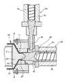
図1は押出成形された円筒状成形体を直線状に切開しながら接着ゴムを積層した短繊維配向ゴムシートにする工程の概略図である。この工程では、製造装置1を使用する。本装置1では、シリンダー3a内の押出スクリュー4aの回転により短繊維含有ゴムを混練する第一押出機2aと、シリンダー3b内の押出スクリュー4bの回転により短繊維を含有しないゴムを混練する第二押出機2bが、それぞれ押出したゴムを拡張ダイ5の背部に連結し、軸部6と筒部7で形成されたゴム通路8へと導入する。 FIG. 1 is a schematic view of a process for producing a short fiber oriented rubber sheet in which adhesive rubber is laminated while cutting an extruded cylindrical molded body in a straight line. In this step, the manufacturing apparatus 1 is used. In this apparatus 1, the
上記拡張ダイ5では、軸部6に装着された内ダイ10が筒部7に連結された外ダイ13と組み合わせて拡張したゴム通路8を形成している。内ダイ10は入口11から吐出口12に向って徐々に径を拡張させた円錐体である。外ダイ13の入口11付近には、調芯用ブロック体14を組み合わせて押出しゴムの厚みを均一にすることができる。 In the
短繊維を含有しない接着ゴム16を混練し押出す第二押出機2bは、第一押出機2aに比べて入口11に近い側に配置され、先に押出された短繊維含有ゴム15の外周部に接着ゴム16を流動させて包囲した二層の筒状成形体17に押出成形する。接着ゴム16はゴムの流動性がよく短繊維含有ゴム15の外周を完全に包囲できる。押出された筒状成形体17は切断手段19によって切開された後、巻き取られる。 The
第一押出機2a及び第二押出機2bでは、シリンダー3a,3bの中に回転可能に押出スクリュー4a,4bを収容し、ゴム配合物を原料投入口から入れて押出スクリュー4a,4bの回転によってゴムとを混練にする。この時にシリンダー3a,3b内の空気やゴム配合物から発生したガス等は排気口(図示せず)から排出される。シリンダー3a,3bの温度はゴム種に応じて変更するが、通常40〜100°Cに調節され、短繊維とゴムはミキシングしやすい温度に加熱して熱可塑化し、押出成形しやすい状態にする。また、この場合の混練時間はゴムの加硫が進行しない程度に調節する。 In the
拡張ダイ5は内ダイ10を吐出口12に向って径を徐々に拡張させて円錐形とし、これを外ダイ13に収容し、内ダイ10と外ダイ13の間に所定厚みの間隙を設けている。短繊維混入ゴム15は吐出口12に向って徐々に大きな円周方向への引き伸ばしを受けながら短繊維を円周方向に配向させ、同時に接着ゴム16を外層に包囲した筒状成形体17に押出成形する。 The expansion die 5 gradually expands the diameter of the
拡張ダイ5は、水平に配置された第一押出機2aと第二押出機2bに対して垂直に配置され、そして吐出口12から筒状成形体17が重力に抗するように押出されるため、筒状成形体17が重力により変形せず、比較的寸法変化が少ない。また、垂直方向に配置した拡張ダイ5は内ダイ10の自重によって撓みにくく、内ダイ10と外ダイ13との間隙が一定に保持され、厚み変形量の小さな筒状成形体17に仕上げることができる。 The
また、内ダイ10と外ダイ13で形成されたゴム通路8は、入口11から吐出口12まで略均一な間隙になり、筒状成形体17の押出にブレーキをかけることなく長手方向へスムーズに流し、また内部歪みのない均一な厚みの筒状成形体17に仕上げる。 Further, the
内ダイ10の形状は、せん断力の大きさに影響を与える要因になる。入口11から吐出口12に向って徐々に径が拡張するテーパー角度が30°以上で90°未満であり、入口が直径20〜60mm、吐出口が直径100〜440mm、そしてその比率である拡張比(吐出口/入口)が1.5〜12.5に設定される。この設定範囲未満であれば、内ダイ10の吐出口12付近での円周方向への引き伸ばしが小さくて、厚みの大きな筒状成形体17の内外層では短繊維が円周方向に配向しにくくなり、一方この設定範囲を越えると、円周方向への引き伸ばしが大きくなり過ぎて、押出圧力が劣る場合には、筒状成形体17が裂けやすい。 The shape of the
内ダイ10と外ダイ13間のゴム通路8内に存在するゴムの内部発熱を抑制するために、内ダイ10の内部に冷却水を循環させる冷却装置(図示せず)を設けることもできる。冷却装置では、内ダイ10及び外ダイ13内へ冷却水を入れポンプによって各ダイに設けた通路を通過させて各ダイから排出し、循環させる。 In order to suppress internal heat generation of the rubber existing in the
切断手段19は、図5に示すような筒状成形体17を押出し方向に沿って切開しながら、図6に示すような二層ゴムシート20にし、カッター、ナイフといった刃物、あるいはレーザーナイフ、超音波振動カッターからなる。二層ゴムシート20はガイドロールを経由して駆動ロールによって一定速度で送られ、巻き取りロールに帆布のようなライナーを積層して巻き取られる。 The cutting means 19 is made into a two-
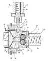
図2に示す接着ゴムを積層した短繊維配向ゴムシートにする他の装置1では、シリンダー3a内の押出スクリュー4aの回転により短繊維含有ゴム15を混練する第一押出機2aと、シリンダー3b内の押出スクリュー4bの回転により短繊維を含有しない接着ゴム16を混練する第二押出機2bが、それぞれ押出したゴムを拡張ダイ5の背部に設けられたゴム通路8へと導入する。 In another apparatus 1 for forming a short fiber oriented rubber sheet laminated with adhesive rubber shown in FIG. 2, a
第一押出機2aは押出スクリュー4aの軸方向に拡張ダイ5を直結し、第二押出機2bは第一押出機2aと直角に配置されている。そして、第二押出機2bから押出された接着ゴム16は、第一押出機2aの押出スクリュー4aの先端部25から離れた位置に設けた整流用突起に衝突すると短繊維含有ゴム15の外周を包囲しやすくなる。 The
拡張ダイ5は吐出口12に向って径を徐々に拡張させて円錐形とした内ダイ10を、これを外ダイ13に収容し、内ダイ10と外ダイ13の間に所定厚みの間隙を設けている。内ダイ10に装着固定した円錐状の分流体27は、ゴムの流れを360度へ均一に分流して、内ダイ10と外ダイ13間のゴム通路8へ押出すようになっている。 The expansion die 5 accommodates the
短繊維混入ゴム15は吐出口12へ向って徐々に大きな円周方向への引き伸ばしを受けながら短繊維を円周方向に配向させ、同時に図5に示すように接着ゴム16を外層に包囲した筒状成形体17に押出成形する。そして、図6に示すように押出された直後の筒状成形体17は、切断手段19によって押出し方向に沿って切開しながら二層ゴムシート20する。
上記短繊維混入ゴム15の厚みは1.5〜10mmで、接着ゴム16の厚みは0.1〜1.0mmである。The short fiber-containing
The short fiber-containing
このように、図2に示す上記装置1は、先に押出した短繊維含有ゴム15の外周面に接着ゴム16を被覆したものを、拡張ダイ5の入口11から同時に押出しして接着ゴム16を短繊維含有ゴム15の外周面に包囲した筒状成形体17に成形するものであるが、図3に示す装置1は短繊維含有ゴム15を拡張ダイ5の入口11から侵入させ、他方接着ゴム16を拡張ダイ5の入口11から吐出口12の間の位置Pで侵入させて接着ゴム16を短繊維含有ゴム15の外周面に包囲した筒状成形体17に押出成形するものである。 As described above, the apparatus 1 shown in FIG. 2 simultaneously extrudes the outer peripheral surface of the short fiber-containing
即ち、図3に示す装置1では、シリンダー3a内の押出スクリュー4aの回転により短繊維含有ゴム15を混練する第一押出機2aがゴムを拡張ダイ5の入口11から吐出口12へ押出す。一方、短繊維を含有しない接着ゴム16を混練する第二押出機2bが第一押出機2aと交差する状態で配置され、接着ゴム16を円周方向に配したゴム溜め部35からゴム通路36を経由して拡張ダイ5の入口11から吐出口12の間の位置Pで円筒状に侵入させる。 That is, in the apparatus 1 shown in FIG. 3, the
上記侵入位置Pでは、図4に示すようにゴム通路8に明確な段差が設けられ、この侵入位置Pから吐出口12へ至るまでのゴム通路8の幅が積層する接着ゴム16の厚み分だけ大きく、接着ゴム16のゴム通路8への侵入抵抗を低下させてスムーズに短繊維含有ゴム15の外周面に包囲しやすくし、そして接着ゴム16の厚みを均一にしている。上記侵入位置Pは、入口11から吐出口12の間であれば問題ないが、好ましくは吐出口12近傍とすることが好ましい。 At the intrusion position P, a clear step is provided in the
図7に示す装置1では、シリンダー3aと拡張ダイ5の間にギアポンプ40が介在し、第一押出機2aにおいてシリンダー3a内の押出スクリュー4aの回転により混練された短繊維含有ゴム15は、噛み合い回転する駆動ギア41と従動ギア42の間を通って、強制的に拡張ダイ5に送り込まれて入口11から吐出口12へ押出される。一方、短繊維を含有しない接着ゴム16を混練する第二押出機2bが第一押出機2aと交差する状態で配置され、接着ゴム16を円周方向に配したゴム溜め部35からゴム通路36を経由して拡張ダイ5の吐出口12近傍の位置Pで円筒状に侵入させる。 In the apparatus 1 shown in FIG. 7, a
侵入位置Pは、入口11から吐出口12の間であれば問題はないが、詳しくは図8に示すように、吐出口12の近傍、具体的にはダイの拡張が終了する位置から吐出口12までの間に侵入位置Pを配置させると、厚みのばらつきが少ないゴムシートが得られる。
本発明者が知見するところでは、短繊維含有ゴムは接着ゴムと比較して硬いため、積層状態で拡張しながら押出しすると接着ゴム層が短繊維含有ゴム層の影響を受けて、得られたゴムシートに波打ちが発生しやすい。しかし侵入位置Pを吐出口12近傍することで、接着ゴム層が短繊維含有ゴム層の影響を受ける距離が短くなり、波打ちが発生し難いといった特徴がある。
尚、侵入位置Pを吐出口12近傍とすることと、シリンダー3aと拡張ダイ5の間にギアポンプ40を介在させこととの組み合わせが必須なわけではなく、これらは単独で実施可能である。There is no problem as long as the intrusion position P is between the inlet 11 and the
As the inventor has found, the short fiber-containing rubber is harder than the adhesive rubber, and therefore, when extruded while being expanded in a laminated state, the adhesive rubber layer is affected by the short fiber-containing rubber layer, and the obtained rubber Waves are likely to occur on the sheet. However, since the intrusion position P is in the vicinity of the
It should be noted that the combination of the intrusion position P in the vicinity of the
上記短繊維含有ゴム15のゴムは、天然ゴム、ブチルゴム、スチレン−ブタジエンゴム、クロロプレンゴム、エチレン−プロピレンゴム、アルキル化クロロスルファン化ポリエチレン、水素化ニトリルゴム、水素化ニトリルゴムと不飽和カルボン酸金属塩との混合ポリマー、エチレン−プロピレンゴム(EPR)やエチレン−プロピレン−ジエンモノマー(EPDM)からなるエチレン−α−オレフィンエラストマー等のゴム材の単独、またはこれらの混合物が使用される。ジエンモノマーの例としては、ジシクロペンタジエン、メチレンノルボルネン、エチリデンノルボルネン、1,4−ヘキサジエン、シクロオクタジエンなどがあげられる。 The rubber of the short fiber-containing
上記ゴムには、アラミド繊維、ポリアミド繊維、ポリエステル繊維、綿等の繊維からなり繊維の長さは繊維の種類によって異なるが1〜10mm程度の短繊維が用いられ、例えばアラミド繊維であると3〜7mm程度、ポリアミド繊維、ポリエステル繊維、綿であると5〜10mm程度のものが用いられる。その添加量はゴム100質量部に対して10〜40質量部である。更に、本発明のゴムには、軟化剤、カーボンブラックからなる補強剤、充填剤、老化防止剤、加硫促進剤、加硫剤等が添加される。 The rubber is made of fibers such as aramid fiber, polyamide fiber, polyester fiber, and cotton, and the length of the fiber varies depending on the type of fiber, but short fibers of about 1 to 10 mm are used. About 7 mm, polyamide fibers, polyester fibers, and cotton are about 5 to 10 mm. The addition amount is 10 to 40 parts by mass with respect to 100 parts by mass of rubber. Furthermore, a softener, a reinforcing agent composed of carbon black, a filler, an antiaging agent, a vulcanization accelerator, a vulcanizing agent, and the like are added to the rubber of the present invention.
上記軟化剤としては、一般的なゴム用の可塑剤、例えばジブチルフタレート(DBP)、ジオクチルフタレート(DOP)等のフタレート系、ジオクチルアジペート(DOA)等のアジペート系、ジオクチルセバケート(DOS)等のセバケート系、トリクレジルホスフェート等のホスフェートなど、あるいは一般的な石油系の軟化剤が含まれる。 Examples of the softening agent include general rubber plasticizers, for example, phthalates such as dibutyl phthalate (DBP) and dioctyl phthalate (DOP), adipates such as dioctyl adipate (DOA), and dioctyl sebacate (DOS). Sebacates, phosphates such as tricresyl phosphate, etc., or general petroleum softeners are included.
本発明では、予めゴム少なくとも短繊維をオープンロール、混練機などによって荒練してマスターバッチを作製することができる。この方法では、オープンロールによってポリマー100質量部に10〜40質量部の短繊維を投入して混練した後、混練したマスターバッチをいったん放出し、これを20〜50°Cまで冷却する。これはゴムのスコーチを防止するためである。 In the present invention, a master batch can be prepared by roughening at least rubber short fibers in advance by an open roll, a kneader or the like. In this method, 10 to 40 parts by mass of short fibers are put into 100 parts by mass of the polymer with an open roll and kneaded, and then the kneaded master batch is discharged once and cooled to 20 to 50 ° C. This is to prevent rubber scorching.
尚、短繊維とともに1〜10質量部の軟化剤を投入することができる。これによって短繊維とゴムのなじみが良くなり、ゴム中への分散が良くなるばかりか、短繊維自体が絡み合って綿状になるのを防ぐ効果がある。即ち、軟化剤が短繊維に浸透し、素繊維同士の絡み合いがほぐれるための潤滑剤としての役割をはたし、短繊維が綿状になるのを阻止し、かつ短繊維とゴムのなじみが良くなって短繊維の分散が良くなる。 In addition, 1-10 mass parts softening agent can be thrown in with a short fiber. This improves the familiarity between the short fibers and the rubber, and not only improves the dispersion in the rubber, but also has an effect of preventing the short fibers themselves from becoming entangled and becoming cottony. In other words, the softener penetrates into the short fibers and acts as a lubricant to loosen the entanglement between the elementary fibers, prevents the short fibers from becoming cottony, and the familiarity between the short fibers and the rubber. Improves the dispersion of short fibers.
一方、接着ゴム16は短繊維含有ゴムで用いたゴムと同じである。上記エチレン−アルファ−オレフィンエラストマーのゴム組成物を使用する場合には、硫黄により架橋できるものを使用する。そして、それ以外に必要に応じてカーボンブラック、シリカのような増強剤、炭酸カルシウム、タルクのような充填剤、可塑剤、安定剤、加工助剤、着色剤のような通常のゴム配合に用いるものが使用される。 On the other hand, the
得られた二層ゴムシートは、Vリブドベルト、ダブルリブドベルト、ローエッジVベルト等の伝動ベルトに適用できる。 The obtained two-layer rubber sheet can be applied to power transmission belts such as V-ribbed belts, double-ribbed belts, and low-edge V-belts.
2a 第一押出機
2b 第二押出機
5 拡張ダイ
8 ゴム通路
10 内ダイ
11 入口
12 吐出口
13 外ダイ
15 短繊維含有ゴム
16 接着ゴム
17 筒状成形体
19 切断手段
20 二層ゴムシート
40 ギアポンプ
P 侵入位置
Claims (6)
Translated fromJapaneseThe method for producing a double-layer rubber sheet for a transmission belt according to any one of claims 1 to 5, wherein the short fiber-containing rubber kneaded with an extrusion screw is passed through a gear pump and then extruded through an expansion die.
Priority Applications (1)
| Application Number | Priority Date | Filing Date | Title |
|---|---|---|---|
| JP2003275262AJP4188172B2 (en) | 2002-07-18 | 2003-07-16 | Method for producing double-layer rubber sheet for transmission belt |
Applications Claiming Priority (3)
| Application Number | Priority Date | Filing Date | Title |
|---|---|---|---|
| JP2002209119 | 2002-07-18 | ||
| JP2002280772 | 2002-09-26 | ||
| JP2003275262AJP4188172B2 (en) | 2002-07-18 | 2003-07-16 | Method for producing double-layer rubber sheet for transmission belt |
Publications (2)
| Publication Number | Publication Date |
|---|---|
| JP2004136649A JP2004136649A (en) | 2004-05-13 |
| JP4188172B2true JP4188172B2 (en) | 2008-11-26 |
Family
ID=32475166
Family Applications (1)
| Application Number | Title | Priority Date | Filing Date |
|---|---|---|---|
| JP2003275262AExpired - Fee RelatedJP4188172B2 (en) | 2002-07-18 | 2003-07-16 | Method for producing double-layer rubber sheet for transmission belt |
Country Status (1)
| Country | Link |
|---|---|
| JP (1) | JP4188172B2 (en) |
Families Citing this family (3)
| Publication number | Priority date | Publication date | Assignee | Title |
|---|---|---|---|---|
| US7128853B2 (en)* | 2002-09-11 | 2006-10-31 | Mitsuboshi Belting Ltd. | Method and apparatus for manufacturing a rubber sheet containing short fibers |
| JP4299110B2 (en)* | 2002-12-26 | 2009-07-22 | 三ツ星ベルト株式会社 | Transmission belt manufacturing method |
| CN106738763B (en)* | 2016-12-16 | 2022-07-26 | 青岛科技大学 | Short fiber radial orientation enhanced annular tire tread extrusion molding and prevulcanization integrated device |
- 2003
- 2003-07-16JPJP2003275262Apatent/JP4188172B2/ennot_activeExpired - Fee Related
Also Published As
| Publication number | Publication date |
|---|---|
| JP2004136649A (en) | 2004-05-13 |
Similar Documents
| Publication | Publication Date | Title |
|---|---|---|
| JP5156881B2 (en) | V-ribbed belt manufacturing method | |
| JP4188172B2 (en) | Method for producing double-layer rubber sheet for transmission belt | |
| JP4299110B2 (en) | Transmission belt manufacturing method | |
| JP2002113764A (en) | Method and apparatus for manufacturing short fiber- containing formed item | |
| JP2006021517A (en) | Manufacturing method of two-layered rubber molded body | |
| JP2004174772A (en) | Method for producing transmission belt | |
| JP3999490B2 (en) | Manufacturing method and apparatus for manufacturing rubber sheet containing short fiber | |
| JP3764413B2 (en) | Transmission belt manufacturing method | |
| JP3718194B2 (en) | Manufacturing method and apparatus for manufacturing rubber sheet containing short fibers | |
| JP4233924B2 (en) | Transmission belt manufacturing method | |
| JP2008162021A (en) | Short fiber-filled rubber cylinder and method for producing the same | |
| JP2004160660A (en) | Method for manufacturing driving belt | |
| JP2002127227A (en) | Method and apparatus for manufacturing staple fiber- containing rubber sheet | |
| JP4133310B2 (en) | Transmission belt manufacturing method | |
| JP2003211554A (en) | Manufacturing method for transmission belt | |
| JP3752207B2 (en) | Manufacturing method of rubber sheet containing short fiber for transmission belt | |
| JP2004175103A (en) | Producing method for rubber sheet containing short fiber | |
| JP2005014304A (en) | Method and apparatus for manufacturing short fiber-containing rubber sheet | |
| JP2002127225A (en) | Method and apparatus for manufacturing short fiber- filled rubber sheet | |
| JP2003001720A (en) | Method for producing transmission belt | |
| CN101524889B (en) | Method and apparatus for manufacturing a rubber sheet containing short fibers | |
| JP2003136610A (en) | Method for manufacturing transmission belt | |
| JP2002192595A (en) | Apparatus for manufacturing short fiber-mixed rubber sheet and die unit used therefor | |
| JP2006069220A (en) | Manufacturing process of transmission belt and transmission belt | |
| JP2007245578A (en) | Method of manufacturing rubber sheet containing short fiber |
Legal Events
| Date | Code | Title | Description |
|---|---|---|---|
| A621 | Written request for application examination | Free format text:JAPANESE INTERMEDIATE CODE: A621 Effective date:20060607 | |
| A977 | Report on retrieval | Free format text:JAPANESE INTERMEDIATE CODE: A971007 Effective date:20080814 | |
| TRDD | Decision of grant or rejection written | ||
| A01 | Written decision to grant a patent or to grant a registration (utility model) | Free format text:JAPANESE INTERMEDIATE CODE: A01 Effective date:20080909 | |
| A01 | Written decision to grant a patent or to grant a registration (utility model) | Free format text:JAPANESE INTERMEDIATE CODE: A01 | |
| A61 | First payment of annual fees (during grant procedure) | Free format text:JAPANESE INTERMEDIATE CODE: A61 Effective date:20080910 | |
| R150 | Certificate of patent or registration of utility model | Ref document number:4188172 Country of ref document:JP Free format text:JAPANESE INTERMEDIATE CODE: R150 Free format text:JAPANESE INTERMEDIATE CODE: R150 | |
| FPAY | Renewal fee payment (event date is renewal date of database) | Free format text:PAYMENT UNTIL: 20110919 Year of fee payment:3 | |
| FPAY | Renewal fee payment (event date is renewal date of database) | Free format text:PAYMENT UNTIL: 20120919 Year of fee payment:4 | |
| FPAY | Renewal fee payment (event date is renewal date of database) | Free format text:PAYMENT UNTIL: 20130919 Year of fee payment:5 | |
| R250 | Receipt of annual fees | Free format text:JAPANESE INTERMEDIATE CODE: R250 | |
| LAPS | Cancellation because of no payment of annual fees |