JP4186446B2 - Address translation method - Google Patents
Address translation methodDownload PDFInfo
- Publication number
- JP4186446B2 JP4186446B2JP2001274419AJP2001274419AJP4186446B2JP 4186446 B2JP4186446 B2JP 4186446B2JP 2001274419 AJP2001274419 AJP 2001274419AJP 2001274419 AJP2001274419 AJP 2001274419AJP 4186446 B2JP4186446 B2JP 4186446B2
- Authority
- JP
- Japan
- Prior art keywords
- protocol
- address
- dns
- information
- alg
- Prior art date
- Legal status (The legal status is an assumption and is not a legal conclusion. Google has not performed a legal analysis and makes no representation as to the accuracy of the status listed.)
- Expired - Fee Related
Links
Images


Classifications
- H—ELECTRICITY
- H04—ELECTRIC COMMUNICATION TECHNIQUE
- H04L—TRANSMISSION OF DIGITAL INFORMATION, e.g. TELEGRAPHIC COMMUNICATION
- H04L12/00—Data switching networks
- H04L12/28—Data switching networks characterised by path configuration, e.g. LAN [Local Area Networks] or WAN [Wide Area Networks]
- H04L12/46—Interconnection of networks
- H04L12/4641—Virtual LANs, VLANs, e.g. virtual private networks [VPN]
- H—ELECTRICITY
- H04—ELECTRIC COMMUNICATION TECHNIQUE
- H04L—TRANSMISSION OF DIGITAL INFORMATION, e.g. TELEGRAPHIC COMMUNICATION
- H04L61/00—Network arrangements, protocols or services for addressing or naming
- H—ELECTRICITY
- H04—ELECTRIC COMMUNICATION TECHNIQUE
- H04L—TRANSMISSION OF DIGITAL INFORMATION, e.g. TELEGRAPHIC COMMUNICATION
- H04L61/00—Network arrangements, protocols or services for addressing or naming
- H04L61/09—Mapping addresses
- H04L61/25—Mapping addresses of the same type
- H04L61/2503—Translation of Internet protocol [IP] addresses
- H04L61/251—Translation of Internet protocol [IP] addresses between different IP versions
- H—ELECTRICITY
- H04—ELECTRIC COMMUNICATION TECHNIQUE
- H04L—TRANSMISSION OF DIGITAL INFORMATION, e.g. TELEGRAPHIC COMMUNICATION
- H04L61/00—Network arrangements, protocols or services for addressing or naming
- H04L61/09—Mapping addresses
- H04L61/25—Mapping addresses of the same type
- H04L61/2503—Translation of Internet protocol [IP] addresses
- H04L61/256—NAT traversal
- H04L61/2564—NAT traversal for a higher-layer protocol, e.g. for session initiation protocol [SIP]
- H—ELECTRICITY
- H04—ELECTRIC COMMUNICATION TECHNIQUE
- H04L—TRANSMISSION OF DIGITAL INFORMATION, e.g. TELEGRAPHIC COMMUNICATION
- H04L61/00—Network arrangements, protocols or services for addressing or naming
- H04L61/45—Network directories; Name-to-address mapping
- H—ELECTRICITY
- H04—ELECTRIC COMMUNICATION TECHNIQUE
- H04L—TRANSMISSION OF DIGITAL INFORMATION, e.g. TELEGRAPHIC COMMUNICATION
- H04L69/00—Network arrangements, protocols or services independent of the application payload and not provided for in the other groups of this subclass
- H04L69/08—Protocols for interworking; Protocol conversion
- H—ELECTRICITY
- H04—ELECTRIC COMMUNICATION TECHNIQUE
- H04L—TRANSMISSION OF DIGITAL INFORMATION, e.g. TELEGRAPHIC COMMUNICATION
- H04L69/00—Network arrangements, protocols or services independent of the application payload and not provided for in the other groups of this subclass
- H04L69/16—Implementation or adaptation of Internet protocol [IP], of transmission control protocol [TCP] or of user datagram protocol [UDP]
- H04L69/167—Adaptation for transition between two IP versions, e.g. between IPv4 and IPv6
- H—ELECTRICITY
- H04—ELECTRIC COMMUNICATION TECHNIQUE
- H04L—TRANSMISSION OF DIGITAL INFORMATION, e.g. TELEGRAPHIC COMMUNICATION
- H04L69/00—Network arrangements, protocols or services independent of the application payload and not provided for in the other groups of this subclass
- H04L69/16—Implementation or adaptation of Internet protocol [IP], of transmission control protocol [TCP] or of user datagram protocol [UDP]
Landscapes
- Engineering & Computer Science (AREA)
- Computer Networks & Wireless Communication (AREA)
- Signal Processing (AREA)
- Computer Security & Cryptography (AREA)
- Data Exchanges In Wide-Area Networks (AREA)
- Computer And Data Communications (AREA)
- Communication Control (AREA)
Description
Translated fromJapanese【0001】
【発明の属する技術分野】
本発明は同一のプロトコルに従う網、あるいは、異なるプロトコルに従う網を相互接続する方式に関する。
【0002】
【従来の技術】
例えばプライベート網どうしをインターネットで接続し、ひとつのVPN(Virtual Private Network)として見せる技術として、Twice NAT(Network Address TRanslation)技術を使う方法(http://www.ietf.org/rfc/rfc2663.txtのpp12-13参照)や、トンネル技術を使う方法(http://www.ietf.org/rfc/rfc2663.txtのpp22参照)が知られている。いずれも基本的にIPパケットのヘッダ情報をIPv4とIPv4とで相互に変換する。
例えば基本的なNATは、プライベートIPv4アドレスとパブリックIPv4アドレスの変換を行う。NATを2つ直列に接続した、いわゆるTwice NAT技術を実装したルータはTwice NATルータと呼ばれる。従来の基本NAT、双方向NATでは、送信元アドレス、もしくは着信先アドレスのどちらか一方を書き換えていたが、Twice NAT技術では、Twice NATルータで接続された二つの領域間をデータグラムが通過する時点で、送信元アドレスと着信先アドレスの両方を書き換える。
Twice NATは、プライベートネットワーク内のアドレス空間とパブリック空間のアドレス空間が衝突している場合に使われることが多い。あるサイトのアドレス付けを誤って他のサイトのパブリックアドレスをつけてしまった場合、あるプロバイダからアドレスをもらっていたが、他のプロバイダに乗り換えた後もしばらくは、以前のプロバイダから割り当ててもらったアドレスを使い続け、そのプロバイダが別ユーザに対して同じアドレスを割り当ててしまった場合に、アドレス衝突が発生する。アドレス衝突を解決するためには、Twice NATは以下のように動作する。プライベート領域内のHost-Aがパブリック領域内のHost-Xと通信をはじめる場合には、Host-A はHost-XのDNSアドレス問い合わせパケットを送信する。DNS-ALG(Domain Name Service - Application Level Gateway)がこのパケットを捕捉し、かつHost-Xに対するアドレスをプライベート領域内でルーティング可能なアドレス(Host-XPRIME)に変換してHost-Aに返す。DNSアドレス解決が終了したらHost-AはHost-XPRIMEとの間で通信を開始する。このパケットがTwice NATを通過する時点で、送信元アドレスがNATの持つアドレスに書き換えられ、着信先アドレスはHost-Xに書き換わる。Host-Xからの返信パケットもこれと同様の変換が行われる。上記DNS-ALGの動作詳細については、http://www.ietf.orf/rfc/rfc2693.txtに詳細が記載されている。
Twice NATを使用する方法は、インターネットを介して多数のホストどうしで通信する場合に、大容量の変換テーブルが必要になる。特定のIPアドレスを使うアプリケーションが多い場合には、上記のようにDNSアドレス問い合わせをトリガにしたNATによるダイナミックなアドレス変換ができないという問題がある。
上記の問題点を解決するために、NAT技術ではなくトンネル技術を用いて二つの領域を相互接続する方法がある。トンネル技術を用いる方法は、接続対象になっている二つの網内の端末が同一のアドレスを持つ場合には、同一のアドレスを有する端末間では通信ができない、異なる接続する二つの領域が同一のサブネットを持たないといけないという制限がある。しかしながら、Twice NAT使用時のように大容量の変換テーブルを持つ必要はないので、インターネットを介して同一のサブネット空間を共有するPrivate VLAN(Virtual LAN)どうしを相互接続する技術としてはトンネル技術が使われることが多い。
以上の例は、ある端末が属する網と通信相手の端末が属する網の通信プロトコルが同一の場合に使われる技術である。ある端末が属する網と通信相手の端末が属する網の通信プロトコルが異なる場合には、例えばプロトコルとしてIPv4を用いる網(以下IPv4網と呼ぶ)とInternet Protocol version 6を使用する網(以下IPv6網と呼ぶ)を接続する変換方式としてNAT-PT(http://www.ietf.org/rfc/rfc2766.txtのpp6-18、およびrfc2765.txtのpp9-22参照)、SOCKS64(http://search.ietf.org/internet-drafts/draft-ietf-ngTRans-socks-gateway-05.txt参照)等が知られている。
いずれも基本的にIPパケットのフォーマットをIPv4とIPv6とで相互に変換する。例えば、IPv4アドレスとIPv6アドレスの変換を行う。この変換を行う装置を以下トランスレータと呼ぶ。トランスレータでは変換のために、変換の前にIPv4アドレスとIPv6アドレスの対応関係を作成し、保持しておく必要がある。この対応関係を通信が発生するたびに動的に作成する場合に、そのきっかけとしてDNS(ドメインネームシステム)の名前解決が利用される(アスキー出版、インターネットRFC事典、pp323-329を参照)。
DNSはウェブのURLのような人間にわかりやすい名前(文字列)を、IPアドレスに変換するシステムである。以下名前をIPアドレスに変換する操作を名前解決と呼ぶ。今日ではインターネット上のほぼすべてのアプリケーションがこのDNSを利用して通信相手のIPアドレスを取得している。
NAT、及びトランスレータはこの事実を利用し、通信開始にあたってやり取りされるDNSのメッセージを常に監視しており、名前解決の要求メッセージを変換情報(IPアドレスの対応関係等)を作成するきっかけとする。具体的には、IPv6端末がある名前について名前解決を行ったとき、その応答であるIPアドレスがIPv4だった場合、このIPv4アドレスをIPv6アドレスに書き換えてIPv6端末に送り返す。そして、書き換える前のIPv4アドレスと書き換えたIPv6アドレスを対応付ける。つまりDNS-ALGは名前解決の応答メッセージを横取りして書き換え、この書き換える前と書き換えた情報をもとに変換情報を作成する。ここで動的に作成された変換情報は一時的なものであるから、通信が終了すると廃棄される。DNS-ALGが保持する、IPv4アドレスとIPv4アドレスの対応関係、若しくはIPv4アドレスとIPv6アドレスの対応関係は通信終了とともに廃棄され、通信ごとに異なるものが使用される。すなわち、名前解決の応答メッセージを書き換える内容が通信ごとに異なる。したがって、名前解決を要求した端末から見ると、同じ名前に対して異なるIPアドレスを取得することとなる。
【0003】
このように、DNS-ALGとトランスレータの連携は、インターネット上のほぼすべてのアプリケーションがこのDNSを利用して通信相手のIPアドレスを動的に取得している状況において、IPv6ネットワークとIPv4ネットワークを接続するために必須の技術である。また、DNS-ALGとTwice NATの連携は、パブリックアドレスの移行時に発生するIPv4プライベートアドレスの競合問題を解決する技術である。
【0004】
【発明が解決しようとする課題】
上述した通り、トンネル方式によるVPNの相互接続は、IPアドレスの衝突に対処できないという課題がある。また、DNS-ALGとTwice NATの連携は、パブリックアドレスの移行時に発生するIPv4プライベートアドレスの競合問題を解決する技術である。しかし、DNS-ALGとTwice NATの連携は、アドレス変換テーブルが大きく、スケーラブルでないという課題がある。一般的に、VPN間の相互接続は、VPNのエッジにDNS-ALGとTwice NATを設置し、実現することが多い。しかし、相互接続するVPNの数が多い場合、アドレス変換テーブルが大きくなるため、サービスの提供が困難であるという課題がある。
本発明の目的は、ある端末が属する網と通信相手の端末が属する網の通信プロトコルが同一の場合に、両網のアドレス空間が衝突した場合にも、両方の端末どうしの通信を可能にすることにある。本発明の他の目的は、ある端末が属する網と通信相手の端末が属する網の通信プロトコルが異なる場合には、基本トランスレーションによって、両方の端末どうしの通信を可能にする、スケーラブルで実用的なアドレス変換装置を提供することにある。
【0005】
本発明はIPv6ベースのDNS-ALGとTwice NAT-PTの連携によって、従来のTwice NATによるアドレス変換で必要な変換情報を動的に作成する場合に必要であった、着側の端末に対する仮想アドレスを生成するDNS-ALGの処理負荷の軽減と大容量変換テーブルの削減を可能にする。
【0006】
本発明によるIPv6ベースのDNS-ALGとTwice NAT-PTをプロバイダが一括管理し、トランスレータに複数のVPNを収容すれば、既存のVPNを置きかえることなく、複数のVPN間での相互接続が可能になる。
【0007】
【課題を解決するための手段】
従来の、NAT-PTに代表されるプロトコル変換方式に加え、少なくとも以下の2点の手段を備える。すなわち、▲1▼複数のトランスレータがもつ、IPv4アドレスとIPv6アドレスの対応関係に代表されるアドレス変換に必要な変換情報を管理するDNS-ALG装置を備え、▲2▼各トランスレータは前記DNS-ALG装置と通信を行うためのプロトコルを備える。
【0008】
Twice NAT-PTによるアドレス変換で必要な変換情報を動的に作成するため、DNS-ALG装置は、発側の端末からの送信される着側端末に対するDNS問い合わせを、装置の内部では一度IPv6に変換する。DNS-ALG装置は、着側のIPv4 DNSサーバにおける問い合わせで取得したIPv4の実アドレスに仮想IPv6プレフィックスを付加したIPv6アドレスを着側の端末に対する仮想IPv6アドレスとして使用する。仮想IPv6アドレスを仮想IPv4アドレスに変換し、発側端末に通知する。この方式をとることによって、従来のTwice NAT方式と比較すると、変換回数が一回少なくなると同時に変換テーブルのサイズを小さくすることができる。
さらに、▲3▼各トランスレータはL2情報を活用してプロトコル変換を行う手段を備えてもよい。IPアドレス以外にもMACアドレスに代表されるL2情報を用いたプロトコル変換を行う手段を備えることによって、1つの物理回線上に複数のVPNを多重することが可能になる。
このような発明を適用した情報網は、第1の網と、第1の網と通信可能な第2の網と、第2の網と通信可能な第3の網と、第1の網と第2の網を接続する第1のアドレス変換装置と、第2の網と第3の網を接続する第2のアドレス変換装置とを有し、第1のアドレス変換装置は、第1の網で使われているアドレスに第1の網を示すプレフィックスを付加した第1仮想アドレスを、第2の網を介して第2のアドレス変換装置に送り、第2のアドレス変換装置は、第1仮想アドレスを第3の網で使われていないアドレスである第2仮想アドレスに変換して第3の網に送り、第1仮想アドレスと第2仮想アドレスとの対応情報を記憶する。また、第3の網から送られてきた第2仮想アドレスを、対応情報に基づいて第1仮想アドレスに変換し、第1仮想アドレスからプレフィックスを削除して、第1の網に送る。この場合、第1の網は第1のプロトコルに従い、第2及び第3の網は第2のプロトコルに従うこととしてもよい。また、変換されるアドレスは、送信元アドレスまたは送信先アドレスとしてもよい。
【0009】
このような網に用いられる通信装置としては、第1の網と第2の網の間に配置され、第1の網と第2の網の間の通信を仲介する通信装置であって、第1の網から送られてきた第1の網で使われている元アドレスを受信し、元アドレスにプレフィックスを付加した第1仮想アドレスを形成し、第1仮想アドレスを第2の網に送出し、第2の網から送られてきた第1仮想アドレスを受信し、第1仮想アドレスからプレフィックスを削除して元アドレスを形成し、元アドレスを第1の網に送出する。
【0010】
また、他の通信装置は、第2の網から送られてきた第1アドレスを、第1の網で使われていない第2アドレスに変換し、第1の網に送出し、第1アドレスと第2アドレスの関連を変換情報として保持し、第1の網から送られてきた第2アドレスを、変換情報にもとづいて第1アドレスに変換し、第1アドレスを第2の網に送出する。
【0011】
【発明の実施の形態】
本発明の第1の実施の形態を図面を用いて説明する。
【0012】
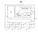
図1は、本発明によるVPN間接続サービスを提供するネットワークの構成例を示す。VPN間接続サービスを提供するネットワークは、VPN5とIP網6から構成される。VPN5は、DNSサーバ3を備える。VPN5aは、例えば企業の拠点(1001、1002)を仮想的に相互に接続する。本実施例では、VPN5は、IPv4プライベートアドレスを利用する。1つのVPN内においてはIPアドレスは重複しないが、異なるVPNの間でIPアドレスは重複してもよい。IP網6はDNSサーバ8を備える。本実施例では、IP網6はIPv6アドレスを利用する。
【0013】
VPN5とIP網6は、トランスレータ1(TR)で接続する。トランスレータ1は、IPv6アドレスとIPv4アドレスの変換機能と、DNS-ALG2と通信する手段を備える。DNS-ALG2は、複数のトランスレータがもつIPv4アドレスとIPv6アドレスの対応関係に代表されるアドレス変換に必要な変換情報を管理し、DNSの問い合わせやその返信のパケットの中身を書き換える手段を備える。第1の実施の形態において、DNS-ALG2は、VPN5毎に存在する。
【0014】
図2は、トランスレータ1の構成例を示す。トランスレータ1は、回線(17a、17b、17c、17n)を収容するインタフェース部(IF)(16a、16b、16c、16n)と、メモリ14と、CPU15とを、スイッチまたはバス18で接続する構成となっている。メモリ14は、アドレスの変換に必要な情報11やデータパケットを変換するためのプログラム13や、DNS-ALG2からの変換エントリ登録要求を処理するためのプログラム12が格納されている。変換情報記憶部11は、図9に示す仮想プレフィックス管理テーブル300と図11に示す変換情報テーブル500を備える。
【0015】
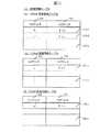
図9は、仮想プレフィックス管理テーブル300のテーブル構成を示す。本テーブルは、トランスレータ1の回線番号ごとに生成された複数のエントリ(300−1〜300−n)からなる。各エントリは、回線番号301対応に、仮想プレフィックス302と、変換情報テーブル500へのポインタ303を定義する。
【0016】
図11は、変換情報テーブル500のテーブル構成を示す。本テーブルには、IPv4アドレス501とIPv6アドレス502の対応関係が格納される。本テーブルは、VPN毎に生成され(510、520、530)、VPNを収容するトランスレータ1の変換情報記憶部11に格納される。例えば、図1において、VPN#1変換情報テーブル510はトランスレータ1aに、VPN#3変換情報テーブル530はトランスレータ1bに格納される。
【0017】
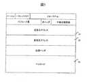
図2へ戻りトランスレータ1の説明を続ける。変換エントリ登録処理12は、変換情報登録要求を処理し、IPアドレスの対応情報を変換情報記憶部11の変換情報テーブル500に格納する。データパケット変換・処理部13は、IPv4パケットを受信すると変換情報記憶部11を検索し、IPv6アドレスをIPv4アドレスに書き換える。また、データパケット変換・処理部13は、IPv6パケットを受信すると、変換情報記憶部11を検索し、IPv4アドレスをIPv6アドレスに書き換える。このとき、IPアドレスのほかにもさまざまな情報を書き換えることが可能である。図4にIPv4パケットフォーマットを示す。図5にIPv6パケットのフォーマットを示す。変換の際にはIPアドレスだけでなく、このフォーマットも変換する。
【0018】
図3は、DNS-ALG2の構成例を示す。DNS-ALG2は、回線(24a、24b)を収容するインタフェース部(IF)(23a、23b)と、メモリ22と、CPU21とを、バス25で接続する構成となっている。
【0019】
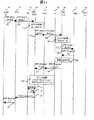
図14と図15に示すシーケンスに従って、図1におけるVPN5aの端末4aがVPN5cの端末4cと通信する場合について説明する。通信開始にあたり、端末4aは端末4cの名前(hostCとする)のアドレスを得るため、DNSサーバ3aに対してDNS問い合わせを行う(101)。DNS問い合わせのパケットフォーマットを図6に示す。
図6に示すように、QNAME(421)に名前hostCが、QTYPE(422)に資源レコードのタイプ”A”が記載される。
図14に戻り説明を続ける。DNSサーバ3aはこの名前hostCに対応するIPアドレスを知らないため、次のDNSサーバ(DNS-ALG2a)に対してDNS問い合わせを行う(102)。
【0020】
DNS-ALG2aは、名前hostCに対するIPアドレスを知らない場合、図12、13に示す処理ルーチン60を起動する。DNS問い合わせのQTYPEが“A”の場合、DNS-ALG2aはQTYPEを“AAAA”に変換する(62、103)。DNS-ALG2aは変換したDNS問い合わせを次のDNSサーバ8に送信し(63、104)、DNS応答を待つ(64)。DNSサーバ8は、次のDNSサーバ(DNS-ALG2b)にDNS問い合わせを送信する(105)。DNS-ALG2bは、名前hostCに対するIPアドレスを知らない場合、図12、13に示す処理ルーチン60を起動する。DNS問い合わせのQTYPEが“AAAA”の場合、QTYPEを“A”に変換する(81、106)。DNS-ALG2bは変換したDNS問い合わせを次のDNSサーバ3cに送信し(82、107)、DNS応答を待つ(83)。DNSサーバ3cは、名前hostCに対するIPv4アドレス“c”を応答する(84、108)。
【0021】
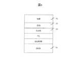
図7にDNSサーバ3cからのDNS応答パケットのフォーマットを示す。図7の43、44、45の詳細フォーマットを図8に示す。NAME(51)に名前hostC、RDATA(54)にIPアドレス“c”が記載される。
図14を参照すると、DNS-ALG2bは以後の変換のためにIPv4アドレス“c”をIPv6アドレス“γ+c”に書き換える。このIPv6アドレスは、VPN5cに対して割り当てられる仮想的なIPv6プレフィックス(γ)+IPv4アドレス(c)で構成される(109)。以降、このアドレスを「着信先仮想IPv6アドレス」と呼ぶ。DNS-ALG2bは、DNS応答のTYPE(52)を“A”から“AAAA”に変換し、RDATA(54)に“γ+c”を設定したDNS応答をDNSサーバ8に送信する(85、110)。DNSサーバ8は、DNS-ALG2aに名前hostCに対する着信先仮想IPv6アドレス“γ+c”を応答する(65、111)。
DNS-ALG2aは、以後の変換のために、このIPv6アドレス“γ+c”をIPv4アドレスc'に変換する(112)。このIPv4アドレスは名前hostCに対する仮想的なアドレスで、VPN5aで使用されていないIPアドレスの集合から選ぶ。以降、このアドレスを「着信先仮想IPv4アドレス」と呼ぶ。DNS-ALG2aは、DNS応答のTYPE(52)を“AAAA”から“A”に変換し、RDATA(54)に着信先仮想IPv4アドレス”c'”を設定したDNS応答をDNSサーバ3a経由で端末4aに送信する(66、115、116)。このとき、γ+cとc'の対応付け変換規則を作成し、トランスレータ1aに送信する(67、113)。
トランスレータ1aは、変換規則を変換情報記憶部11内のVPN#1変換情報テーブル510に記憶し、DNS-ALG2aに応答を送信する(114)。
【0022】
DNS応答を受信した端末4aは端末4cへ向けてIPパケットの送信を始める。これらのパケットの着信先アドレスはc'、送信元アドレスは端末のIPv4アドレスaである(131)。
【0023】
トランスレータ1aは、このパケットが到着するとデータパケット変換・処理部13に送る。ここでは、変換情報記憶部11にデータを受信した回線の番号と着信先アドレスc'で検索をかける。すると、ステップ113で準備したエントリが変換情報テーブル510に見つかるため、着信先アドレス“c'”を“γ+C”に変換する。送信元アドレスは、データを受信した回線番号に対応する仮想的なIPv6プレフィックスαを付加した「送信元仮想IPv6アドレス」“α+a”に書き換える(132)。トランスレータ1aは着信先アドレスに“γ+c”、送信元アドレスに“α+a”をそれぞれ設定したパケットを送信する(133)。
トランスレータ1bはこのパケットをデータパケット変換・処理部13に送る。ここでは、着信先アドレスから仮想IPv6プレフィックスγを削除する。送信元アドレス“α+a”をVPN5cの内部で一意に識別するため、IPv4アドレス“a1'”に変換する。このIPv4アドレスは、送信元アドレス“α+a”に対する仮想的なアドレスで、VPN5cの内部で使用されていないIPアドレスの集合から選ぶ。以降、このアドレスを「送信元仮想IPv4アドレス」と呼ぶ。
【0024】
トランスレータ1bは、“α+a”と“a1'”の対応付け変換規則を作成し、変換情報記憶部11のVPN#3変換情報テーブル530に記憶する(134)。
端末4cが着信先アドレスに“c”、送信元アドレスに“a1'”を設定したパケットを受信する(135)。端末4cは、端末4aへ向けて着信先アドレス“a1'”、送信元アドレス“c”を設定したIPパケットを送信する(136)。トランスレータ1bではこのパケットが到着するとデータパケット変換・処理部13に送る。ここでは、変換情報記憶部11にデータを受信した回線の番号と着信先アドレス“a1'”で検索をかける。すると、ステップ134で準備したエントリが変換情報テーブル530に見つかるため、着信先アドレスを“a1'”を“α+a”に変換する。送信元アドレスは、データを受信した回線番号に対応する仮想的なIPv6プレフィックスγを付加した送信元仮想IPv6アドレス“γ+c”に書き換える(137)。トランスレータ1bは着信先アドレスに“α+a”、送信元アドレスに“γ+c”を設定したパケットを送信する(138)。
【0025】
トランスレータ1aは、このパケットが到着するとデータパケット変換・処理部13に送る。ここで、着信先アドレスから仮想IPv6プレフィックスαを削除する。変換情報記憶部11に着信先アドレスの仮想IPv6プレフィックス“α”と送信元アドレス“γ+c”で検索をかける。すると、さきに準備したエントリが変換情報テーブル510に見つかるため、送信元アドレスを“γ+c”から“c'”に変換する(139)。
【0026】
端末4aは着信先アドレスに“a”、送信元アドレスに“c'”を設定したパケットを受信する(140)。
【0027】
本発明の実施の形態によれば、トランスレータ1とDNS-ALG2が連携し、IP網6の仮想IPv6プレフィックスを活用することにより、プライベートIPv4アドレスを有するVPN間で相互通信を行うことが可能になる。
【0028】
本発明の第2の実施の形態を図面を用いて説明する。
【0029】
図16は、本発明の第2の実施例の網構成を示す。図1と比較すると、図16の網構成は「VPN5のDNSサーバ3とDNS-ALG2の通信がトランスレータ1を経由する」こと、「VPNの相互通信において、DNS-ALG2が次に問い合わせるDNSサーバに、上記DNS-ALG2内の別IPv6アドレスが設定されている」ことを特徴とする。
【0030】
本実施例において、DNS-ALG2は、トランスレータ1に接続されるVPN対応にIPv6アドレスを有するマルチホームノードである。本実施例におけるDNS-ALG2aは、次に問い合わせるDNSサーバがDNS問い合わせを送信したVPNに存在しない場合は、次に問い合わせるDNSサーバのアドレス情報として、DNS-ALG2aの他のIPv6アドレスが記憶されている。次に問い合わせるDNSサーバがDNS問い合わせを送信したVPN内に存在する場合は、次に問い合わせるDNSサーバのアドレス情報として、そのVPN内に存在するDNSサーバの仮想IPv6アドレスが記憶されている。この仮想IPv6アドレスは、“仮想プレフィックス+各VPNにおいて、DNSサーバに割り当てられたIPv4アドレス”で構成される。
【0031】
本実施例におけるトランスレータ1は、VPN毎のDNS-ALGアドレス変換情報と、DNSのメッセージを含むパケットを監視する機能と、DNSのメッセージを含むパケットのアドレス変換機能をさらに備える。VPN毎のDNS-ALGアドレス変換情報は、VPN対応にDNS-ALGのIPv6アドレスとVPNの内部でDNS-ALGを識別するためDNS-ALGに割り当てられた仮想IPv4アドレスとの対応関係を管理する。
【0032】
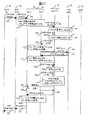
図17と図18に示すシーケンスに従って、図16のVPN5aに存在する端末4aがVPN5bに存在する端末4bと通信する場合について説明する。VPN5aとVPN5bは、トランスレータ1aに接続される。VPN5aとトランスレータ1aの間で送受信するパケットのアドレス変換と、VPN5bとトランスレータ1aの間で送受信するパケットのアドレス変換は、トランスレータ1aで行われる。
図17と図18において、VPN5aとトランスレータ1aの間のアドレス変換機能をTR-O、VPN5bとトランスレータ1aの間のアドレス変換機能をTR-Tと記載する。
【0033】
図14と図17の主な差分は、「トランスレータ1aがDNSのメッセージを含むパケットのアドレスを変換する」ことと、「DNS-ALG2aのIPv6アドレスがVPN毎に異なる」ことである。
【0034】
以下、図17と図18について、詳細に説明する。端末4aは端末4bの名前(hostBとする)を解決するためにDNSサーバ3aに対してDNS問い合わせを行う(151)。DNSサーバ3a(IPv4アドレス“da4”)は、この名前hostBに対応するIPアドレスを知らないため、次のDNSサーバ(DNS-ALG2a、仮想IPv4アドレス“pa4”)に対してDNS問い合わせを行う(152)。
【0035】
トランスレータ1aのTR-Oは、DNSのメッセージを含むパケットを検出し、パケットを変換する(153)。着信先アドレスは、トランスレータ1aが備えるDNS-ALGアドレス変換情報を用いて、DNS-ALG2aのVPN5a用のIPv6アドレス”α6”に変換する。送信元アドレスは、仮想プレフィックス管理テーブル300を参照し、VPN5a用の仮想IPv6プレフィックス“α”を付加する。トランスレータ1aのTR-Oは、アドレスを変換したDNS問い合わせパケットをDNS-ALG2aに送信する(154)。
【0036】
DNS-ALG2aは、名前hostBに対するIPアドレスを知らない場合、前記処理ルーチン60により、DNS問い合わせを変換し(155)、DNS問い合わせを転送する(156)。DNS問い合わせの転送先には、DNS-ALG2aに付与された別のIPv6アドレス(VPN5b用のIPv6アドレス“β6”)が設定されている。
【0037】
VPN5b用のIPv6アドレス“β6”宛のDNS問い合わせを受信したDNS-ALG2aは、名前hostBに対するIPアドレスを知らない場合、前記処理ルーチン60により、変換したDNS問い合わせを次のDNSサーバ3b(仮想IPv6アドレス“β+db4”)に送信する(157、158)。
【0038】
トランスレータ1aのTR-Tは、DNSのメッセージを含むパケットを検出し、パケットを変換する(159)。着信先アドレスから、仮想プレフィックスβを削除する。送信元アドレスは、トランスレータ1aが備えるDNS-ALGアドレス変換情報を用いて、VPN5b用のDNS-ALG2aのIPv6アドレス“β6”に対する仮想IPv4アドレス“pb4”に変換する。トランスレータ1aのTR-Tは、アドレスを変換したパケットをDNSサーバ3bに送信する(160)。
【0039】
DNSサーバ3bは、名前hostBに対するIPv4アドレス“b”を応答する(161)。トランスレータ1aのTR-Tは、DNSのメッセージを含むパケットを検出し、パケットを変換する(162)。送信元アドレスに、VPN5bに対応する仮想プレフィックスβを付加する。着信先アドレスは、トランスレータ1aが備えるDNS-ALGアドレス変換情報を用いて“pb4”から“β6”に変換する。トランスレータ1aのTR-Tは、アドレスを変換したパケットをDNS-ALG2aに送信する(163)。
【0040】
DNS-ALG2aは、名前hostBに対するIPv4アドレス“b”に仮想プレフィックスβを付加し、“β+b”に書き換える(164)。
【0041】
DNS-ALG2aは、DNS-ALG2aのVPN5a用のIPv6アドレス“α6”宛に、RDATAに“β+b”を設定したDNS応答を送信する(165)。
【0042】
DNS応答を受信したDNS-ALG2aは、以後の変換のためにIPv6アドレス“β+b”を着信先仮想IPv4アドレス“b'”に変換する(166)。このIPv4アドレスは名前hostBに対する仮想的なアドレスで、VPN5aで使用されていないIPアドレスの集合から選ぶ。
【0043】
DNS-ALG2aは、DNSサーバ3a経由で端末4aに名前hostBに対する着信先仮想IPv4アドレス“b'”を送信する(169、171、172)。トランスレータ1aはDNS応答169を検出すると、パケットを変換する(170)。着信先アドレスから、仮想プレフィックスαを削除する。送信元アドレスは、トランスレータ1aが備えるDNS-ALGアドレス変換情報を用いて“α6”から“pa4”からに変換する。トランスレータ1aのTR-Oは、アドレスを変換したパケットをDNS3aに送信する(171)。
【0044】
DNS-ALG2aは、“β+b”と“b'”の対応付け変換規則を作成し、トランスレータ1aに送信する(167)。トランスレータ1aは、変換規則を変換情報記憶部11のVPN#1変換情報テーブル510に記憶し、DNS-ALG2aに応答を送信する(168)。
【0045】
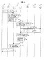
図15と図18の主な差分は、「トランスレータ1は、着信先アドレスと送信元アドレスの変換を行い(182)、パケットをトランスレータ内でルーティングし(184)、再び着信先アドレスと送信元アドレスの変換を行う(185)」ことである。
【0046】
端末4aは端末4bへ向けてIPパケットの送信を始める。これらのパケットの着信先アドレスはb'、送信元アドレスは端末のIPv4アドレスaである(181)。
【0047】
トランスレータ1aは、このパケットが到着するとデータパケット変換・処理部13に送る。ここでは、変換情報記憶部11にデータを受信した回線の番号と着信先アドレスb'で検索をかける。すると、ステップ167で準備したエントリが変換情報テーブル510に見つかるため、着信先アドレスを“b'”を“β+b”に変換する。送信元アドレスには、データを受信した回線番号に対応する仮想的なIPv6プレフィックスαを付加する(182)。
【0048】
トランスレータ1aは着信先アドレスに“β+b”、送信元アドレスに“α+a”を設定したパケットを送信する(183)。このパケットは、トランスレータ1a内でルーティングされる(184)。
【0049】
トランスレータ1aは、このパケットをデータパケット変換・処理部13に送る。ここでは、着信先アドレスから仮想IPv6プレフィックスβを削除する。トランスレータ1aは、送信元アドレス“α+a”をIPv4アドレス“a'”に変換する。このIPv4アドレスは、IPv6アドレス“α+a”に対する仮想的なアドレスで、VPN5bで使用されていないIPアドレスの集合から選ぶ。
【0050】
トランスレータ1aは、“α+a”と“a'”の対応付け変換規則を作成し、変換情報記憶部11のVPN#2変換情報テーブル520に記憶する(185)。
【0051】
端末4bは、着信先アドレスに“b”、送信元アドレスに“a'”を設定したパケットを受信する(186)。
【0052】
端末4bは、端末4aへ向けて着信先アドレス“a'”、送信元アドレス“b”を設定したパケットを送信する(187)。
【0053】
トランスレータ1aはこのパケットが到着するとデータパケット変換・処理部13に送る。ここで、変換情報記憶部11にデータを受信した回線の番号と着信先アドレス“a'”で検索をかける。すると、ステップ185で準備したエントリが変換情報テーブル520に見つかるため、着信先アドレス “a'”を“α+a”に変換する。送信元アドレスには、データを受信した回線番号に対応する仮想的なIPv6プレフィックス“β”を付加する(188)。
【0054】
トランスレータ1aは着信先アドレスに“α+a”、送信元アドレスに“β+b”を設定したパケットをトランスレータ1a内でルーティングする(189、190)。
【0055】
トランスレータ1aは、このパケットをデータパケット変換・処理部13に送る。着信先アドレス“α+a”から仮想IPv6プレフィックスαを削除する。ここで、変換情報記憶部11に着信先の仮想IPv6プレフィックスαと送信元アドレス“β+b”で検索をかけると、さきに準備したエントリが変換情報テーブル510に見つかるため、送信元アドレスを“β+b”から“b'”に変換する(191)。
【0056】
端末4aは着信先アドレスに“a”、送信元アドレスに“b'”を設定したパケットを受信する(192)。
【0057】
本発明の実施の形態によれば、トランスレータとDNS-ALGの連携と、仮想IPv6プレフィックスの活用により、複数のVPNが接続されているトランスレータはアドレスが重複する場合であっても、プライベートIPv4アドレスを有する端末を一意に識別できる。従って、プライベートIPv4アドレスを有するVPN間で相互通信が可能になる。
【0058】
また、VPN毎のDNS-ALGを1つの物理装置に縮退することにより、VPN間でDNS-ALG装置を共有することが可能になる。
【0059】
本発明の第3の実施の形態を図面を用いて説明する。
【0060】
図19は、本発明の第3の実施例の網構成を示す。図16と比較すると、本実施例は、「複数のVPNがDNS-ALGを共有する」ことと、「複数のトランスレータがDNS-ALGを共有する」ことを特徴とする。本実施例におけるDNS-ALG2aは、ドメイン毎に名前解決の転送先を別々に設定する機能を備える。具体的には、次に問い合わせるDNSサーバのアドレス情報として、各VPNのドメイン名とそのVPNに存在するDNSサーバの仮想IPv6アドレスの対応関係を管理する。この仮想IPv6アドレスは、“仮想プレフィックス+各VPNにおいて、DNSサーバに割り当てられたIPv4アドレス”で構成する。
【0061】
DNS-ALG2aは、処理ルーチン60のかわりに、名前hostBのQTYPEの値にかかわらず、“A”及び”AAAA”で名前解決を行う機能を備える。本実施例におけるトランスレータ1は、実施例1におけるトランスレータ1の機能に加え、DNS-ALGアドレス変換情報と、DNSのメッセージを含むパケットを監視する機能と、DNSのメッセージを含むパケットのアドレス変換機能を備える。
【0062】
DNS-ALGアドレス変換情報は、DNS-ALGのIPv6アドレスとVPNの内部でDNS-ALGを識別するためDNS-ALGに割り当てられた仮想IPv4アドレスとの対応関係を管理する。
【0063】
以下、VPN5aに存在する端末4aがVPN5bに存在する端末4bの名前を解決する場合について説明する。
【0064】
本実施例において、トランスレータ1aはDNS-ALG2aのIPv6アドレス“alg6”とVPN毎にVPNの内部でDNS-ALGを識別するためにDNS-ALG2aに割り当てられた仮想IPv6の対応関係を保持する。
【0065】
端末4aは端末4bの名前(hostBとする)のアドレスを得るためにDNS問い合わせを行う。DNSサーバ3aは名前hostBを解決できないため、次のDNSサーバ(DNS-ALG2a)にDNS問い合わせを送信する。このDNS問い合わせのパケットヘッダの着信先アドレスにはDNS-ALG2aに対してVPN5aで割り当てられた仮想IPv4アドレス“pa4”が、送信元アドレスにはDNS3aのIPv4アドレス”da4”が設定される。
【0066】
トランスレータ1aがこのDNS問い合わせを検出すると、DNS-ALGアドレス変換情報を参照して着信先アドレスを“pa4”からDNS-ALG2aのIPv6アドレス“alg6”に変換する。送信元アドレスには、VPN5a用のIPv6プレフィックスαを付加し、“α+da4”に書きかえる。
【0067】
上記DNS問い合わせを受信したDNS-ALG2aは、名前hostBに対するIPアドレスを知らない場合、次のDNSサーバに問い合わせる。ここで、名前hostBを解決するために、次に問い合わせるべきDNSサーバとして、仮想IPv6アドレス“β+db4”が設定される。“β+db4”は、VPN5bのDNSサーバ3bの仮想IPv6アドレスである。
【0068】
DNS-ALG2aは、DNS問い合わせをDNSサーバ3bに送信し、応答を待つ。このDNS問い合わせの送信元アドレスにはDNS-ALG2aのIPv6アドレス“alg6”が、着信先アドレスには“β+db4”が設定される。
【0069】
トランスレータ1aは、上記DNS問い合わせのパケットを検出し、VPN毎のDNS-ALGアドレス変換情報を用いて送信元アドレスを、DNS-ALG2aのIPv6アドレス“alg6”をVPN5b内でDNS-ALG2aを識別する仮想IPv4アドレス“pb4”に変換する。着信先アドレスはプレフィックスβを削除し、“β+db4”から“db4”に書き換える。
【0070】
DNSサーバ3bは、DNS-ALG2aに、名前hostBに対するIPv4アドレス“b”を応答する。
【0071】
DNS-ALG2aは、以後の変換のためにIPv4アドレス“b”を着信先仮想IPv6アドレス “β+b”に書き換えたのち、“β+b”を着信先仮想IPv4アドレス“b'”に変換する。上記IPv4アドレス“b'”は名前hostBに対する仮想的なアドレスで、VPN5aで使用されていないIPアドレスの集合から選ぶ。
【0072】
DNS-ALG2aは、DNSサーバ3a経由で端末4aに名前hostBに対する着信先仮想IPv4アドレス“b'”を送信する。
【0073】
以降の処理の流れは、第2の実施例と同じである。
【0074】
本発明の実施の形態によれば、DNS-ALG がマルチホームノードでない場合であっても、VPN間でDNS-ALGを共用でき、さらにDNS-ALGにおける処理を軽減できる。
【0075】
本発明の第4の実施の形態を図面を用いて説明する。
【0076】
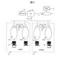
図20は、本発明の第4の実施例の網構成を示す。図16と比較すると、図20の網構成は、「L2SW7がVPN5毎に存在するトランスレータの回線(17a、17b)を多重する」ことを特徴とする。本実施例におけるL2SW7は、図21に示すVPN管理テーブル320を備える。
【0077】
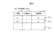
図21は、VPN管理テーブル320のテーブル構成を示す。本テーブルは、MACアドレスやIEEE 802.1QのTAG IDに代表されるレイヤ2(L2)情報毎に生成された複数のエントリ(320−1〜320−n)からなる。各エントリは、L2情報321対応に、VPN識別子322と、対トランスレータの回線番号323を定義する。
【0078】
本実施例において、VPN5aからパケットを受信したL2SW7は、VPN管理テーブル320を受信パケットのL2情報(例えば、送信元MACアドレスや、IEEE 802.1QのTAG ID)で検索する。L2SW7は、VPN5aに対応する回線17aからトランスレータ1aにパケットを送信する。
【0079】
本発明の実施の形態によれば、トランスレータが回線対応に収容するVPNをL2SWで多重することができる。
【0080】
本発明の第5の実施の形態を図面を用いて説明する。
【0081】
図22は、本発明の第5の実施例の網構成を示す。図16と比較すると、図22の網構成は、「トランスレータ1aの回線17aに複数のVPN(5a、5b)が収容される」ことと、「トランスレータ1aが図9に示す仮想プレフィックス管理テーブル300のかわりに図10に示す仮想プレフィックス管理テーブル310を備え、L2情報からVPNを識別する」ことを特徴とする。
【0082】
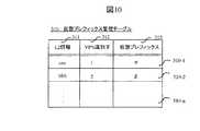
図10は、仮想プレフィックス管理テーブル310のテーブル構成を示す。本テーブルは、MACアドレスやIEEE 802.1QのTAG IDに代表されるレイヤ2(L2)情報毎に生成された複数のエントリ(310−1〜310−n)からなる。各エントリは、L2情報311対応に、VPN識別子312と、仮想プレフィックス313を定義する。
【0083】
本実施例において、VPN5aからパケットを受信したトランスレータ1aは、仮想プレフィックス管理テーブル310を受信パケットのL2情報(例えば、送信元MACアドレスやIEEE 802.1Q TAG ID)で検索する。すると、L2情報に対応する仮想プレフィックスαが仮想プレフィックス管理テーブル310に見つかる。トランスレータ1aは、仮想プレフィックスによりVPNを識別する。
【0084】
本発明の実施の形態によれば、トランスレータの1つの回線に複数のVPNを収容できる。
【0085】
【発明の効果】
以上の実施の形態から明らかなように、本発明はIPv6ベースのDNS-ALGとトランスレータの連携によって、従来のTwice NATによるアドレス変換で必要な変換情報を動的に作成する場合に必要であった、着側の端末に対する仮想アドレスを生成するDNS-ALGの処理負荷の軽減と大容量変換テーブルの削減を可能にする。
【0086】
本発明によるトランスレータとDNS-ALGをプロバイダが一括管理し、トランスレータに複数のVPNを収容すれば、既存のVPNを置きかえることなく、VPN間の相互接続が可能になる。
【図面の簡単な説明】
【図1】本発明の第1の実施例であるIP網を介したVPNの相互接続構成を示すブロック図。
【図2】トランスレータ1の一例のブロック図。
【図3】DNS-ALG2の一例のブロック図。
【図4】IPv4パケットのフォーマット図。
【図5】IPv6パケットのフォーマット図。
【図6】DNS問い合わせのフォーマット図。
【図7】DNS応答のフォーマット図。
【図8】DNS応答の詳細フォーマット図。
【図9】トランスレータ1が備える仮想プレフィックス管理テーブルのテーブル図。
【図10】本発明の第5の実施例において、トランスレータ1が備える仮想プレフィックス管理テーブルのテーブル図。
【図11】トランスレータ1が備える変換情報テーブルのテーブル図。
【図12】DNS-ALG2が備えるDNSメッセージ変換処理ルーチンの流れ図。
【図13】DNS-ALG2が備えるDNSメッセージ変換処理ルーチンの流れ図。
【図14】本発明の第1の実施例における名前解決のシーケンス図。
【図15】本発明の第1の実施例におけるVPNが相互通信する場合のシーケンス図。
【図16】本発明の第2の実施例であるトランスレータに複数のVPNが接続される場合の網構成を示すブロック図。
【図17】本発明の第2の実施例における名前解決のシーケンス図。
【図18】本発明の第2の実施例におけるVPNが相互通信する場合のシーケンス図。
【図19】本発明の第3の実施例である複数のVPNが1つのDNS-ALG装置を利用する場合の網構成を示すブロック図。
【図20】本発明の第4の実施例であるL2SW7がVPNを多重する場合の網構成を示すブロック図。
【図21】本発明の第4の実施例において、L2SW7が備えるVPN管理テーブルのテーブル図。
【図22】本発明の第5の実施例であるトランスレータ1がL2情報を活用してVPNを識別する場合の網構成を示すブロック図。
【符号の説明】
1 トランスレータ、2 DNS-ALG、3 VPN5が備えるDNSサーバ、4 VPNの端末、5 VPN、6 IP網、7 L2SW、8 IP網6が備えるDNSサーバ、31 送信元IPv4アドレス、32 着信先IPv4アドレス、33 IPv4ペイロード、34 送信元IPv6アドレス、35 着信先IPv6アドレス、36 IPv6ペイロード、41 DNSメッセージヘッダ部、42 DNS問い合わせ部、43 DNS応答部、60 DNS変換処理ルーチン。[0001]
BACKGROUND OF THE INVENTION
The present invention relates to a system for interconnecting networks according to the same protocol or networks according to different protocols.
[0002]
[Prior art]
For example, a method using Twice NAT (Network Address TRanslation) technology (http://www.ietf.org/rfc/rfc2663.txt) as a technology to connect private networks over the Internet and show them as one VPN (Virtual Private Network) Pp12-13) and methods using tunnel technology (see pp22 in http://www.ietf.org/rfc/rfc2663.txt) are known. In either case, the header information of the IP packet is basically converted between IPv4 and IPv4.
For example, basic NAT converts private IPv4 addresses and public IPv4 addresses. A router that implements the so-called twice NAT technology, in which two NATs are connected in series, is called a twice NAT router. In the conventional basic NAT and bidirectional NAT, either the source address or the destination address was rewritten, but in the twice NAT technology, the datagram passes between two areas connected by the twice NAT router. At that time, both the source address and the destination address are rewritten.
Twice NAT is often used when the address space in the private network and the public space conflict. If you mistakenly addressed one site and assigned another site's public address, you received an address from one provider, but for a while after switching to another provider, the address assigned by the previous provider If you continue to use and the provider has assigned the same address to another user, an address conflict will occur. In order to resolve address conflicts, Twice NAT works as follows. When Host-A in the private area starts communication with Host-X in the public area, Host-A sends a DNS address inquiry packet of Host-X. DNS-ALG (Domain Name Service-Application Level Gateway) captures this packet, converts the address for Host-X into a routable address (Host-XPRIME) in the private area, and returns it to Host-A. When DNS address resolution is complete, Host-A starts communication with Host-XPRIME. When this packet passes through Twice NAT, the source address is rewritten to the address that NAT has, and the destination address is rewritten to Host-X. The return packet from Host-X is also converted in the same way. Details of the DNS-ALG operation are described in http: //www.ietf.orf/rfc/rfc2693.txt.
The method using Twice NAT requires a large-capacity conversion table when communicating with many hosts via the Internet. When there are many applications that use a specific IP address, there is a problem that dynamic address translation by NAT triggered by a DNS address query cannot be performed as described above.
In order to solve the above problems, there is a method of interconnecting two regions using a tunnel technique instead of a NAT technique. In the method using tunnel technology, when the terminals in the two networks to be connected have the same address, communication between the terminals having the same address is not possible, and the two areas to be connected are the same. There is a restriction that you must have a subnet. However, since it is not necessary to have a large-capacity conversion table unlike when using Twice NAT, tunnel technology is used as a technology for interconnecting private VLANs (Virtual LANs) that share the same subnet space via the Internet. Often.
The above example is a technique used when the communication protocol of the network to which a certain terminal belongs and the network to which the communication partner terminal belongs are the same. If the communication protocol of the network to which a certain terminal belongs and the network to which the communication partner's terminal belongs are different, for example, a network using IPv4 as a protocol (hereinafter referred to as IPv4 network) and a network using Internet Protocol version 6 (hereinafter referred to as IPv6 network). NAT-PT (refer to pp6-18 of http://www.ietf.org/rfc/rfc2766.txt and pp9-22 of rfc2765.txt), SOCKS64 (http: // search .ietf.org / internet-drafts / draft-ietf-ngTRans-socks-gateway-05.txt)) is known.
In either case, the IP packet format is basically converted between IPv4 and IPv6. For example, an IPv4 address and an IPv6 address are converted. An apparatus that performs this conversion is hereinafter referred to as a translator. The translator needs to create and maintain the correspondence between IPv4 address and IPv6 address before conversion for conversion. When this correspondence is dynamically created each time communication occurs, DNS (Domain Name System) name resolution is used as a trigger (see ASCII Publishing, Internet RFC Encyclopedia, pp323-329).
DNS is a system that converts human-friendly names (strings) such as web URLs into IP addresses. Hereinafter, the operation of converting a name to an IP address is called name resolution. Today, almost every application on the Internet uses this DNS to obtain the IP address of the other party.
Using this fact, NAT and translators constantly monitor DNS messages exchanged at the start of communication, and use name resolution request messages as a trigger for creating translation information (IP address correspondences, etc.). Specifically, when name resolution is performed for a certain name of an IPv6 terminal, if the response IP address is IPv4, the IPv4 address is rewritten to an IPv6 address and sent back to the IPv6 terminal. Then, associate the rewritten IPv4 address with the rewritten IPv6 address. In other words, DNS-ALG intercepts and rewrites the name resolution response message, and creates conversion information based on the information before and after the rewriting. Since the dynamically created conversion information is temporary, it is discarded when communication is completed. The correspondence relationship between the IPv4 address and the IPv4 address, or the correspondence relationship between the IPv4 address and the IPv6 address held by the DNS-ALG is discarded at the end of communication, and a different one is used for each communication. That is, the content of rewriting the name resolution response message differs for each communication. Therefore, when viewed from the terminal that requested name resolution, different IP addresses are acquired for the same name.
[0003]
In this way, the linkage between DNS-ALG and the translator connects the IPv6 network and IPv4 network in a situation where almost all applications on the Internet use this DNS to dynamically obtain the IP address of the communication partner. This is an essential technology. DNS-ALG and Twice NAT cooperation is a technology that solves the IPv4 private address conflict problem that occurs during the transition of public addresses.
[0004]
[Problems to be solved by the invention]
As described above, the VPN interconnection by the tunnel method has a problem that it cannot cope with the collision of IP addresses. DNS-ALG and Twice NAT cooperation is a technology that solves the IPv4 private address conflict problem that occurs during the transition of public addresses. However, the linkage between DNS-ALG and Twice NAT has the problem that the address translation table is large and is not scalable. In general, interconnection between VPNs is often realized by installing DNS-ALG and Twice NAT at the edge of VPN. However, when the number of VPNs to be interconnected is large, there is a problem that it is difficult to provide a service because the address conversion table becomes large.
An object of the present invention is to enable communication between both terminals even when the address space of both networks collides when the communication protocol of the network to which a certain terminal belongs and the network to which the communication partner terminal belongs are the same. There is. Another object of the present invention is a scalable and practical communication that enables communication between both terminals by basic translation when the communication protocol of a network to which a terminal belongs and a network to which a communication partner terminal belongs are different. Is to provide a simple address translation device.
[0005]
The present invention is a virtual address for a terminal on the called side, which is necessary when dynamically creating translation information necessary for address translation by conventional Twice NAT by cooperation of IPv6-based DNS-ALG and Twice NAT-PT. This makes it possible to reduce the processing load of DNS-ALG that generates data and reduce the large-capacity conversion table.
[0006]
If the provider collectively manages the IPv6-based DNS-ALG and Twice NAT-PT according to the present invention and accommodates multiple VPNs in the translator, interconnection between multiple VPNs is possible without replacing existing VPNs Become.
[0007]
[Means for Solving the Problems]
In addition to the conventional protocol conversion method represented by NAT-PT, at least the following two means are provided. That is, (1) a DNS-ALG device that manages translation information necessary for address translation represented by the correspondence relationship between IPv4 addresses and IPv6 addresses, possessed by a plurality of translators, and (2) each translator has the DNS-ALG A protocol for communicating with the device is provided.
[0008]
In order to dynamically create the necessary translation information for address translation by Twice NAT-PT, the DNS-ALG device sends a DNS query from the originating terminal to the destination terminal once in IPv6 within the device. Convert. The DNS-ALG device uses an IPv6 address obtained by adding a virtual IPv6 prefix to an IPv4 real address acquired by a query in the destination IPv4 DNS server as a virtual IPv6 address for the terminal on the destination side. The virtual IPv6 address is converted to a virtual IPv4 address and notified to the originating terminal. By adopting this method, the number of conversions can be reduced by one and the conversion table size can be reduced as compared with the conventional twice NAT method.
Further, (3) each translator may be provided with means for performing protocol conversion using L2 information. By providing means for performing protocol conversion using L2 information typified by a MAC address in addition to an IP address, a plurality of VPNs can be multiplexed on one physical line.
An information network to which such an invention is applied includes a first network, a second network that can communicate with the first network, a third network that can communicate with the second network, and a first network. A first address translation device for connecting the second network; and a second address translation device for connecting the second network and the third network. The first address translation device is connected to the first network. The first virtual address obtained by adding a prefix indicating the first network to the address used in the second network is sent to the second address translation device via the second network, and the second address translation device The address is converted into a second virtual address that is not used in the third network and sent to the third network, and correspondence information between the first virtual address and the second virtual address is stored. Also, the second virtual address sent from the third network is converted to the first virtual address based on the correspondence information, the prefix is deleted from the first virtual address, and the second virtual address is sent to the first network. In this case, the first network may follow the first protocol, and the second and third networks may follow the second protocol. The address to be converted may be a source address or a destination address.
[0009]
A communication device used in such a network is a communication device that is arranged between the first network and the second network and mediates communication between the first network and the second network, Receives an original address used in the first network sent from the first network, forms a first virtual address with a prefix added to the original address, and sends the first virtual address to the second network. The first virtual address sent from the second network is received, the prefix is deleted from the first virtual address to form the original address, and the original address is sent to the first network.
[0010]
The other communication device converts the first address sent from the second network into a second address that is not used in the first network, and sends the second address to the first network. The association of the second address is held as conversion information, the second address sent from the first network is converted to the first address based on the conversion information, and the first address is sent to the second network.
[0011]
DETAILED DESCRIPTION OF THE INVENTION
A first embodiment of the present invention will be described with reference to the drawings.
[0012]
FIG. 1 shows a configuration example of a network that provides an inter-VPN connection service according to the present invention. A network that provides an inter-VPN connection service includes a VPN 5 and an
[0013]
VPN 5 and
[0014]
FIG. 2 shows a configuration example of the
[0015]
FIG. 9 shows a table configuration of the virtual prefix management table 300. This table includes a plurality of entries (300-1 to 300-n) generated for each line number of the
[0016]
FIG. 11 shows a table configuration of the conversion information table 500. In this table, the correspondence between the
[0017]
Returning to FIG. 2, the description of the
[0018]
FIG. 3 shows a configuration example of DNS-ALG2. The DNS-
[0019]
The case where the terminal 4a of the
As shown in FIG. 6, the name hostC is written in QNAME (421), and the resource record type “A” is written in QTYPE (422).
Returning to FIG. 14, the description will be continued. Since the
[0020]
When the DNS-
[0021]
FIG. 7 shows a format of a DNS response packet from the
Referring to FIG. 14, DNS-
The DNS-
The
[0022]
The terminal 4a that has received the DNS response starts transmitting an IP packet toward the terminal 4c. The destination address of these packets is c ', and the source address is the IPv4 address a of the terminal (131).
[0023]
When this packet arrives, the
The
[0024]
The
The terminal 4c receives a packet in which “c” is set as the destination address and “a1 ′” is set as the source address (135). The terminal 4c transmits an IP packet in which the destination address “a1 ′” and the source address “c” are set to the
[0025]
When this packet arrives, the
[0026]
The terminal 4a receives a packet in which “a” is set as the destination address and “c ′” is set as the source address (140).
[0027]
According to the embodiment of the present invention, the
[0028]
A second embodiment of the present invention will be described with reference to the drawings.
[0029]
FIG. 16 shows the network configuration of the second embodiment of the present invention. Compared with FIG. 1, the network configuration of FIG. 16 is that “the communication between the
[0030]
In this embodiment, the DNS-
[0031]
The
[0032]
A case where the terminal 4a existing in the
17 and 18, the address conversion function between the
[0033]
The main difference between FIG. 14 and FIG. 17 is that “the
[0034]
Hereinafter, FIGS. 17 and 18 will be described in detail. The terminal 4a makes a DNS inquiry to the
[0035]
The TR-O of the
[0036]
When the DNS-
[0037]
When the DNS-
[0038]
The TR-T of the
[0039]
The
[0040]
The DNS-
[0041]
The DNS-
[0042]
The DNS-
[0043]
The DNS-
[0044]
The DNS-
[0045]
The main difference between FIG. 15 and FIG. 18 is that “
[0046]
The terminal 4a starts transmitting an IP packet toward the terminal 4b. The destination address of these packets is b ', and the source address is the IPv4 address a of the terminal (181).
[0047]
When this packet arrives, the
[0048]
The
[0049]
The
[0050]
The
[0051]
The terminal 4b receives the packet in which “b” is set as the destination address and “a ′” is set as the source address (186).
[0052]
The terminal 4b transmits a packet in which the destination address “a ′” and the source address “b” are set to the
[0053]
When this packet arrives, the
[0054]
The
[0055]
The
[0056]
The terminal 4a receives a packet in which “a” is set as the destination address and “b ′” is set as the source address (192).
[0057]
According to the embodiment of the present invention, due to the cooperation between a translator and DNS-ALG and the use of a virtual IPv6 prefix, a translator to which multiple VPNs are connected has a private IPv4 address even if the addresses overlap. It is possible to uniquely identify the terminal that has it. Therefore, mutual communication is possible between VPNs having private IPv4 addresses.
[0058]
Also, by degenerating DNS-ALG for each VPN into one physical device, it becomes possible to share the DNS-ALG device between VPNs.
[0059]
A third embodiment of the present invention will be described with reference to the drawings.
[0060]
FIG. 19 shows the network configuration of the third embodiment of the present invention. Compared with FIG. 16, the present embodiment is characterized in that “a plurality of VPNs share DNS-ALG” and “a plurality of translators share DNS-ALG”. The DNS-
[0061]
The DNS-
[0062]
The DNS-ALG address translation information manages the correspondence between the DNS-ALG IPv6 address and the virtual IPv4 address assigned to the DNS-ALG in order to identify the DNS-ALG inside the VPN.
[0063]
Hereinafter, a case where the terminal 4a existing in the
[0064]
In the present embodiment, the
[0065]
The terminal 4a makes a DNS inquiry to obtain the address of the name (host B) of the terminal 4b. Since the
[0066]
When the
[0067]
The DNS-
[0068]
The DNS-
[0069]
The
[0070]
The
[0071]
The DNS-
[0072]
The DNS-
[0073]
The subsequent processing flow is the same as in the second embodiment.
[0074]
According to the embodiment of the present invention, even when the DNS-ALG is not a multihomed node, the DNS-ALG can be shared between VPNs, and the processing in the DNS-ALG can be further reduced.
[0075]
A fourth embodiment of the present invention will be described with reference to the drawings.
[0076]
FIG. 20 shows the network configuration of the fourth embodiment of the present invention. Compared with FIG. 16, the network configuration of FIG. 20 is characterized in that “
[0077]
FIG. 21 shows a table configuration of the VPN management table 320. This table includes a plurality of entries (320-1 to 320-n) generated for each layer 2 (L2) information typified by a MAC address and IEEE 802.1Q TAG ID. Each entry defines a
[0078]
In the present embodiment, the
[0079]
According to the embodiment of the present invention, VPNs accommodated by the translator corresponding to the line can be multiplexed by L2SW.
[0080]
A fifth embodiment of the present invention will be described with reference to the drawings.
[0081]
FIG. 22 shows the network configuration of the fifth embodiment of the present invention. Compared with FIG. 16, the network configuration of FIG. 22 is that “a plurality of VPNs (5a, 5b) are accommodated in the
[0082]
FIG. 10 shows a table configuration of the virtual prefix management table 310. This table includes a plurality of entries (310-1 to 310-n) generated for each layer 2 (L2) information typified by a MAC address and IEEE 802.1Q TAG ID. Each entry defines a
[0083]
In this embodiment, the
[0084]
According to the embodiment of the present invention, a plurality of VPNs can be accommodated in one line of a translator.
[0085]
【The invention's effect】
As is clear from the above embodiments, the present invention was necessary when dynamically creating translation information necessary for address translation by conventional twice NAT by cooperation of IPv6-based DNS-ALG and a translator. This makes it possible to reduce the processing load of DNS-ALG that generates a virtual address for the called terminal and to reduce the large-capacity conversion table.
[0086]
If the provider and the DNS-ALG according to the present invention are collectively managed by a provider and a plurality of VPNs are accommodated in the translator, interconnection between VPNs becomes possible without replacing existing VPNs.
[Brief description of the drawings]
FIG. 1 is a block diagram showing a VPN interconnection configuration via an IP network according to a first embodiment of the present invention.
FIG. 2 is a block diagram of an example of a
FIG. 3 is a block diagram of an example of DNS-ALG2.
FIG. 4 is a format diagram of an IPv4 packet.
FIG. 5 is a format diagram of an IPv6 packet.
FIG. 6 is a format diagram of a DNS inquiry.
FIG. 7 is a format diagram of a DNS response.
FIG. 8 is a detailed format diagram of a DNS response.
FIG. 9 is a table diagram of a virtual prefix management table provided in the
FIG. 10 is a table of a virtual prefix management table provided in the
FIG. 11 is a table diagram of a conversion information table provided in the
FIG. 12 is a flowchart of a DNS message conversion processing routine provided in DNS-ALG2.
FIG. 13 is a flowchart of a DNS message conversion processing routine provided in DNS-ALG2.
FIG. 14 is a sequence diagram of name resolution in the first embodiment of the present invention.
FIG. 15 is a sequence diagram when VPNs communicate with each other in the first embodiment of the present invention.
FIG. 16 is a block diagram showing a network configuration when a plurality of VPNs are connected to a translator according to a second embodiment of the present invention.
FIG. 17 is a sequence diagram of name resolution in the second embodiment of the present invention.
FIG. 18 is a sequence diagram when VPNs communicate with each other in the second embodiment of the present invention.
FIG. 19 is a block diagram showing a network configuration when a plurality of VPNs according to the third embodiment of the present invention use one DNS-ALG device.
FIG. 20 is a block diagram showing a network configuration when
FIG. 21 is a table showing a VPN management table provided in the
FIG. 22 is a block diagram showing a network configuration when a
[Explanation of symbols]
1 Translator, 2 DNS-ALG, 3 DNS server provided by VPN5, 4 VPN terminal, 5 VPN, 6 IP network, 7 L2SW, 8 DNS server provided by
Claims (20)
Translated fromJapanese前記サーバ装置は、前記アドレス変換装置が前記第1プロトコルを内部で第2プロトコルに相互に変換するための変換情報と、前記第1プロトコルに従う網に対応する前記第2プロトコルに従うアドレスとを備え、かつ前記変換情報を作成するために他のサーバ装置、もしくは上記サーバ装置の別のアドレスと通信する手段を有し、
前記アドレス変換装置は、前記DNS-ALGから供給される情報に基づいて前記第1プロトコルを内部で第2プロトコルに相互に変換する手段と、前記サーバ装置と連携して、前記第1プロトコルのアドレスと前記第2プロトコルのアドレスとの対応関係を含む変換情報を作成する手段とを有し、前記第1プロトコルに従う網から前記第2プロトコルに従う網への通信について、前記変換情報を参照して前記第1プロトコルに従うアドレスから前記第2プロトコルに従うアドレスに変換し、変換された第2プロトコルに従うアドレスをさらに第1プロトコルに従うアドレスに変換することを特徴とする通信網。A communication comprising a plurality of networks according to a first protocol, an address translation device that connects the plurality of networks and internally converts the first protocol into a second protocol, a server device, and DNS-ALG A net,
The server device includes translation information for the address translation device to mutually translate the first protocol into a second protocol, and an address according to the second protocol corresponding to a network according to the first protocol, And means for communicating with another server device or another address of the server device to create the conversion information,
The address translation device is configured to mutually translate the first protocol into a second protocol based on information supplied from the DNS-ALG, and in cooperation with the server device, the address of the first protocol. And a means for creating conversion information including a correspondence relationship between the address of the second protocol and the address of the second protocol, and referring to the conversion information for communication from the network according to the first protocol to the network according to the second protocol A communication network, wherein an address according to the first protocol is converted into an address according to the second protocol, and the converted address according to the second protocol is further converted into an address according to the first protocol.
前記多重装置は、前記第1プロトコルに従う網から通信要求を受信したとき、レイヤ2の情報により前記第1プロトコルに従う網を特定し、対応する回線を用いて前記アドレス変換装置に通信要求を送信することを特徴とする請求項1に記載の通信網。A plurality of devices connected to the network according to the first protocol and further connected to the address translation device via a plurality of lines, when the multiplexer receives a communication request from the network according to the first protocol, 2. The communication network according to claim 1, wherein a network conforming to the first protocol is specified based on layer 2 information, and a communication request is transmitted to the address translation device using a corresponding line.
DNS-ALGから供給される情報に基づいて、前記第1プロトコルを内部で第2プロトコルに相互に変換する手段と、
前記サーバと通信する通信手段と、
前記アドレス変換装置が前記第1プロトコルを内部で第2プロトコルに相互に変換するための変換情報と、前記第1プロトコルに従う網に対応する前記第2プロトコルに従うアドレスとを備え、かつ前記変換情報を作成するために他のサーバ装置、もしくは上記サーバ装置の別のアドレスと通信するサーバ装置と連携して、前記第1プロトコルのアドレスと前記第2プロトコルのアドレスとの対応関係を含む変換情報を作成する手段とを有することを特徴とするアドレス変換装置。An address translation device connected to a plurality of networks according to a first protocol,
Means for mutually converting the first protocol to the second protocol internally based on information supplied from DNS-ALG;
Communication means for communicating with the server;
The address translation device includes translation information for mutually translating the first protocol into a second protocol internally, and an address according to the second protocol corresponding to a network according to the first protocol, and the translation information To create the conversion information including the correspondence between the address of the first protocol and the address of the second protocol in cooperation with another server device or a server device communicating with another address of the server device. And an address conversion device.
前記アドレス変換装置は、
前記第1プロトコルを内部で第2プロトコルに相互に変換する手段と、
前記サーバと通信する通信手段とを有し、
前記網は、
前記第1プロトコルに従う網に対応する前記第2プロトコルに従うアドレスと、
前記アドレス変換装置が前記第1プロトコルを内部で第2プロトコルに相互に変換するための変換情報と、
前記変換情報を作成するために他のサーバ装置、もしくは上記サーバ装置の別のアドレスと通信する手段と、
前記アドレス変換装置へ、DNS-ALGから供給される情報に基づいた、前記第1プロトコルのアドレスと前記第2プロトコルのアドレスとの対応関係を含む変換情報の作成を要求する手段とを有することを特徴とする通信網。A communication network for connecting a plurality of networks according to a first protocol with an address translation device,
The address translator is
Means for internally converting the first protocol to a second protocol;
Communication means for communicating with the server,
The net is
An address according to the second protocol corresponding to a network according to the first protocol;
Translation information for the address translation device to mutually translate the first protocol into a second protocol;
Means for communicating with another server device or another address of the server device to create the conversion information;
Means for requesting the address translation device to create translation information including a correspondence relationship between the address of the first protocol and the address of the second protocol based on information supplied from the DNS-ALG. A featured communication network.
前記サーバ装置は、前記アドレス変換装置が前記第1プロトコルを内部で第2プロトコルに相互に変換するための変換情報と、
前記第1プロトコルに従う網の識別情報と前記第1プロトコルに従う網に属するサーバ装置に付与される前記第2プロトコルに従うアドレスの対応関係を管理し、前記第1プロトコルに従う網の名前解決要求を受信するときに、前記対応関係を参照して他のサーバ装置と通信する手段と、
前記アドレス変換装置へ、DNS-ALGから供給される情報に基づいた、前記第1プロトコルのアドレスと前記第2プロトコルのアドレスとの対応関係を含む変換情報の作成を要求する手段とを有することを特徴とするサーバ装置。A server device provided in a communication network for connecting a plurality of networks according to a first protocol with an address translation device,
The server device includes: conversion information for the address translation device to mutually convert the first protocol into a second protocol;
Manages the correspondence between the network identification information according to the first protocol and the address according to the second protocol assigned to the server device belonging to the network according to the first protocol, and receives a name resolution request for the network according to the first protocol And means for communicating with other server devices by referring to the correspondence relationship;
Means for requesting the address translation device to create translation information including a correspondence relationship between the address of the first protocol and the address of the second protocol based on information supplied from the DNS-ALG. A server device as a feature.
Priority Applications (5)
| Application Number | Priority Date | Filing Date | Title |
|---|---|---|---|
| JP2001274419AJP4186446B2 (en) | 2001-09-11 | 2001-09-11 | Address translation method |
| US10/061,331US7085270B2 (en) | 2001-09-11 | 2002-02-04 | Address translation method |
| DE60238659TDE60238659D1 (en) | 2001-09-11 | 2002-02-07 | Address translation method |
| EP02002039AEP1303106B1 (en) | 2001-09-11 | 2002-02-07 | Address translation method |
| US11/447,995US7630374B2 (en) | 2001-09-11 | 2006-06-07 | Address translation method |
Applications Claiming Priority (1)
| Application Number | Priority Date | Filing Date | Title |
|---|---|---|---|
| JP2001274419AJP4186446B2 (en) | 2001-09-11 | 2001-09-11 | Address translation method |
Related Child Applications (1)
| Application Number | Title | Priority Date | Filing Date |
|---|---|---|---|
| JP2008033946ADivisionJP4572938B2 (en) | 2008-02-15 | 2008-02-15 | Address translation method |
Publications (2)
| Publication Number | Publication Date |
|---|---|
| JP2003087336A JP2003087336A (en) | 2003-03-20 |
| JP4186446B2true JP4186446B2 (en) | 2008-11-26 |
Family
ID=19099448
Family Applications (1)
| Application Number | Title | Priority Date | Filing Date |
|---|---|---|---|
| JP2001274419AExpired - Fee RelatedJP4186446B2 (en) | 2001-09-11 | 2001-09-11 | Address translation method |
Country Status (4)
| Country | Link |
|---|---|
| US (2) | US7085270B2 (en) |
| EP (1) | EP1303106B1 (en) |
| JP (1) | JP4186446B2 (en) |
| DE (1) | DE60238659D1 (en) |
Families Citing this family (66)
| Publication number | Priority date | Publication date | Assignee | Title |
|---|---|---|---|---|
| US7684786B2 (en)* | 2003-08-26 | 2010-03-23 | Nokia Corporation | Method and system for establishing a connection between network elements |
| JP4349766B2 (en) | 2001-12-07 | 2009-10-21 | 株式会社日立製作所 | Address translation device |
| JP4010830B2 (en)* | 2002-03-05 | 2007-11-21 | 富士通株式会社 | Communication apparatus and network system |
| KR100485801B1 (en)* | 2002-03-07 | 2005-04-28 | 삼성전자주식회사 | Network connecting apparatus and method for offering direct connection between network devices existing different private networks |
| US7440471B1 (en)* | 2002-04-17 | 2008-10-21 | Mcafee, Inc. | System and method for facilitating IPv6 protocol usage by an application program |
| US7191331B2 (en)* | 2002-06-13 | 2007-03-13 | Nvidia Corporation | Detection of support for security protocol and address translation integration |
| US7333510B1 (en)* | 2002-07-12 | 2008-02-19 | Cisco Technology, Inc. | Method and apparatus for providing IPv6 networks to communicate with overlapping IPv4 networks using NAT-PT |
| US7694018B2 (en)* | 2002-11-19 | 2010-04-06 | Hewlett-Packard Development Company, L.P. | Method and system for communication between two devices by editing machine specific information at a proxy server |
| EP1429523A1 (en)* | 2002-12-13 | 2004-06-16 | Alcatel | Public addressing supported by temporary private addressing |
| US7948916B2 (en)* | 2003-01-31 | 2011-05-24 | Hewlett-Packard Development Company, L.P. | Method and apparatus for discovering topology information in a network |
| US20040153502A1 (en)* | 2003-02-04 | 2004-08-05 | Luliang Jiang | Enhanced DNS server |
| US7450499B2 (en)* | 2003-02-21 | 2008-11-11 | Samsung Electronics Co., Ltd. | Method and apparatus for interconnecting IPv4 and IPv6 networks |
| US7526562B1 (en)* | 2003-04-11 | 2009-04-28 | Cisco Technology, Inc. | Stateful IPv4-IPv6 DNS application level gateway for handling topologies with coexisting IPv4-only, Ipv6-only and dual-stack devices |
| US7864780B1 (en)* | 2003-04-29 | 2011-01-04 | Cisco Technology, Inc. | Apparatus and methods for handling name resolution over IPV6 using NAT-PT and DNS-ALG |
| US7391768B1 (en)* | 2003-05-13 | 2008-06-24 | Cisco Technology, Inc. | IPv4-IPv6 FTP application level gateway |
| JP4271988B2 (en) | 2003-05-19 | 2009-06-03 | 株式会社日立コミュニケーションテクノロジー | Packet communication device |
| US7447203B2 (en) | 2003-07-29 | 2008-11-04 | At&T Intellectual Property I, L.P. | Broadband access for virtual private networks |
| US20050066041A1 (en)* | 2003-09-19 | 2005-03-24 | Chin Kwan Wu | Setting up a name resolution system for home-to-home communications |
| US7640319B1 (en)* | 2003-09-30 | 2009-12-29 | Nortel Networks Limited | Gateway shared by multiple virtual private networks |
| US8051177B1 (en) | 2003-09-30 | 2011-11-01 | Genband Us Llc | Media proxy having interface to multiple virtual private networks |
| US7593388B1 (en)* | 2003-09-30 | 2009-09-22 | Nortel Networks Limited | Convertor shared by multiple virtual private networks |
| US8271620B2 (en)* | 2003-11-13 | 2012-09-18 | Lantronix, Inc. | Communication protocol converter and method of protocol conversion |
| TW200529623A (en)* | 2004-01-14 | 2005-09-01 | Nec Corp | Communication encryption method, communication encryption system, terminal device, DNS server and program |
| US7584420B2 (en)* | 2004-02-12 | 2009-09-01 | Lockheed Martin Corporation | Graphical authoring and editing of mark-up language sequences |
| CN100426804C (en)* | 2004-05-21 | 2008-10-15 | 华为技术有限公司 | Method for implementing mixed website VPN |
| US20050271047A1 (en)* | 2004-06-02 | 2005-12-08 | Huonder Russell J | Method and system for managing multiple overlapping address domains |
| US20050271050A1 (en)* | 2004-06-04 | 2005-12-08 | Utstarcom, Inc. | Domain-influenced prefix assignment method and apparatus |
| JP4052298B2 (en)* | 2004-09-30 | 2008-02-27 | ブラザー工業株式会社 | Information display program and device |
| CN1758649B (en)* | 2004-10-05 | 2010-04-28 | 华为技术有限公司 | Method for interworking between internetwork protocol networks with different versions |
| JP4033187B2 (en)* | 2004-10-08 | 2008-01-16 | ブラザー工業株式会社 | Setting management program, management device and setting management system |
| US20080052281A1 (en) | 2006-08-23 | 2008-02-28 | Lockheed Martin Corporation | Database insertion and retrieval system and method |
| US20060256814A1 (en)* | 2005-05-13 | 2006-11-16 | Lockheed Martin Corporation | Ad hoc computer network |
| US20060256717A1 (en)* | 2005-05-13 | 2006-11-16 | Lockheed Martin Corporation | Electronic packet control system |
| US20060256770A1 (en)* | 2005-05-13 | 2006-11-16 | Lockheed Martin Corporation | Interface for configuring ad hoc network packet control |
| US7599289B2 (en) | 2005-05-13 | 2009-10-06 | Lockheed Martin Corporation | Electronic communication control |
| CN100459572C (en)* | 2005-06-23 | 2009-02-04 | 华为技术有限公司 | Message transformation realizing method based on port from IPv4 to IPv6 network |
| US8804759B2 (en)* | 2006-02-28 | 2014-08-12 | Hewlett-Packard Development Company, L.P. | Network name resolution into network address |
| KR100781523B1 (en)* | 2006-04-25 | 2007-12-03 | 삼성전자주식회사 | IP identification packet configuration and IP allocation apparatus, IP identification packet configuration and IP allocation method using the same |
| JP4558674B2 (en)* | 2006-05-02 | 2010-10-06 | 日本電信電話株式会社 | SIP communication system, SIP communication control apparatus, SIP communication control method, and computer program |
| JP2008017279A (en)* | 2006-07-07 | 2008-01-24 | Fujitsu Ltd | Communication control method for ad hoc network |
| US8265073B2 (en)* | 2006-10-10 | 2012-09-11 | Comcast Cable Holdings, Llc. | Method and system which enables subscribers to select videos from websites for on-demand delivery to subscriber televisions via a television network |
| JP2009017429A (en)* | 2007-07-09 | 2009-01-22 | Fujitsu Ltd | Network relay control program, network relay control device, and network relay control method |
| CN101141420B (en)* | 2007-09-05 | 2012-07-11 | 杭州华三通信技术有限公司 | Method and system for performing data communication between private network and public network |
| CN101952810B (en)* | 2007-10-24 | 2013-10-30 | 兰特罗尼克斯公司 | Various methods and devices for assigning virtual IP addresses by central station |
| US8635440B2 (en)* | 2007-12-13 | 2014-01-21 | Microsoft Corporation | Proxy with layer 3 security |
| US8369343B2 (en)* | 2008-06-03 | 2013-02-05 | Microsoft Corporation | Device virtualization |
| KR20100040658A (en)* | 2008-10-10 | 2010-04-20 | 삼성전자주식회사 | Method and apparatus for preventing ip address conflict in remote access service of upnp network |
| US8300637B1 (en)* | 2009-01-05 | 2012-10-30 | Sprint Communications Company L.P. | Attribute assignment for IP dual stack devices |
| US8208377B2 (en)* | 2009-03-26 | 2012-06-26 | Force10 Networks, Inc. | MAC-address based virtual route aggregation |
| US9480092B2 (en)* | 2009-04-23 | 2016-10-25 | Qualcomm Incorporated | Establishing packet data network connectivity for local internet protocol access traffic |
| JP4760963B2 (en)* | 2009-06-26 | 2011-08-31 | 株式会社日立製作所 | IPv6 address assignment method |
| JP2013502190A (en)* | 2009-08-20 | 2013-01-17 | エヌイーシー ヨーロッパ リミテッド | Method and network structure for controlling traffic within a network structure |
| CN102055755B (en)* | 2009-10-29 | 2013-10-23 | 杭州华三通信技术有限公司 | A method for data communication between a public network and a private network and a secure card insertion |
| CN102263833B (en)* | 2010-05-28 | 2014-08-06 | 中国移动通信集团公司 | Method and equipment for determining terminal translating type |
| US8719449B2 (en)* | 2010-11-29 | 2014-05-06 | Telefonaktiebolaget L M Ericsson (Publ) | Identification of a private device in a public network |
| US8660143B2 (en)* | 2011-02-07 | 2014-02-25 | International Business Machines Corporation | Data packet interception system |
| JP6040711B2 (en) | 2012-10-31 | 2016-12-07 | 富士通株式会社 | Management server, virtual machine system, program, and connection method |
| US9008096B2 (en)* | 2012-11-13 | 2015-04-14 | Microsoft Technology Licensing, Llc | Data packet routing |
| CN102984300B (en)* | 2012-12-13 | 2015-11-18 | 北京邮电大学 | Distributed network gate system and access method in a kind of 4-6-4 hybrid protocol network |
| JP5997367B2 (en)* | 2013-03-26 | 2016-09-28 | Kddi株式会社 | Transfer device |
| US9521219B2 (en)* | 2014-01-20 | 2016-12-13 | Echelon Corporation | Systems, methods, and apparatuses using common addressing |
| GB2539286B (en)* | 2014-04-22 | 2021-10-27 | Pismo Labs Technology Ltd | Methods and systems for processing a DNS request |
| US9894033B2 (en) | 2014-08-04 | 2018-02-13 | Fortinet, Inc. | DNS-enabled communication between heterogeneous devices |
| US9930004B2 (en) | 2015-10-13 | 2018-03-27 | At&T Intellectual Property I, L.P. | Method and apparatus for expedited domain name system query resolution |
| CN105450515B (en)* | 2015-11-12 | 2018-06-12 | 清华大学 | A kind of IPv4/IPv6 data translations gateway and method for application layer protocol |
| CN113992629B (en)* | 2021-09-09 | 2023-11-07 | 新华三信息安全技术有限公司 | Address allocation method and device |
Family Cites Families (7)
| Publication number | Priority date | Publication date | Assignee | Title |
|---|---|---|---|---|
| JP3531367B2 (en)* | 1996-07-04 | 2004-05-31 | 株式会社日立製作所 | Translator |
| US6580717B1 (en)* | 1996-07-04 | 2003-06-17 | Hitachi, Ltd. | Packet communication method and apparatus and a recording medium storing a packet communication program |
| EP1773013B1 (en)* | 1996-11-01 | 2013-05-22 | Hitachi, Ltd. | Communicating method between IPv4 terminal and IPv6 terminal and IPv4-IPv6 converting apparatus |
| EP1087575A1 (en) | 1999-09-24 | 2001-03-28 | BRITISH TELECOMMUNICATIONS public limited company | Packet network interfacing |
| US7072933B1 (en)* | 2000-01-24 | 2006-07-04 | Microsoft Corporation | Network access control using network address translation |
| AU2000264879A1 (en)* | 2000-08-17 | 2002-02-25 | Advanced Network Technology Laboratories Pte Ltd | Reconfigurable computer networks |
| US7437474B2 (en)* | 2001-02-22 | 2008-10-14 | Intel Corporation | Proxy-less packet routing between private and public address realms |
- 2001
- 2001-09-11JPJP2001274419Apatent/JP4186446B2/ennot_activeExpired - Fee Related
- 2002
- 2002-02-04USUS10/061,331patent/US7085270B2/ennot_activeExpired - Fee Related
- 2002-02-07EPEP02002039Apatent/EP1303106B1/ennot_activeExpired - Lifetime
- 2002-02-07DEDE60238659Tpatent/DE60238659D1/ennot_activeExpired - Lifetime
- 2006
- 2006-06-07USUS11/447,995patent/US7630374B2/ennot_activeExpired - Fee Related
Also Published As
| Publication number | Publication date |
|---|---|
| EP1303106A3 (en) | 2004-08-04 |
| DE60238659D1 (en) | 2011-02-03 |
| US20060227780A1 (en) | 2006-10-12 |
| EP1303106A2 (en) | 2003-04-16 |
| EP1303106B1 (en) | 2010-12-22 |
| US7085270B2 (en) | 2006-08-01 |
| US7630374B2 (en) | 2009-12-08 |
| US20030048804A1 (en) | 2003-03-13 |
| JP2003087336A (en) | 2003-03-20 |
Similar Documents
| Publication | Publication Date | Title |
|---|---|---|
| JP4186446B2 (en) | Address translation method | |
| US7231452B2 (en) | Method and apparatus for communicating on a communication network | |
| JP4234482B2 (en) | Dynamic DNS registration method, domain name resolution method, proxy server, and address translation device | |
| JP4075318B2 (en) | Protocol conversion method and address conversion server | |
| US7158526B2 (en) | Packet communication method and apparatus and a recording medium storing a packet communication program | |
| US7315543B2 (en) | Apparatus and method for data communication on packet-switching network | |
| US7701952B2 (en) | Packet communication method and apparatus and a recording medium storing a packet communication program | |
| KR100485801B1 (en) | Network connecting apparatus and method for offering direct connection between network devices existing different private networks | |
| TWI441493B (en) | System and method for connection of hosts behind nats | |
| US7639686B2 (en) | Access network clusterhead for providing local mobility management of a roaming IPv4 node | |
| US20070094411A1 (en) | Network communications system and method | |
| CN103338151B (en) | Public network client accesses the method and router of private network server | |
| WO2010108431A1 (en) | Method for realizing ipv6 host visting ipv4 host, method for obtaining ipv6 address prefix and translation device | |
| JP4572938B2 (en) | Address translation method | |
| CN110691150A (en) | SDN-based IPv4 and IPv6 interconnection method and system | |
| JP3915230B2 (en) | PACKET GENERATION METHOD, INFORMATION PROCESSING DEVICE HAVING ITS FUNCTION, AND RECORDING MEDIUM CONTAINING PACKET GENERATION PROGRAM | |
| EP3395049B1 (en) | Router and method for connecting an ipv4 network and an ipv6 network | |
| Cabellos et al. | An Architectural Introduction to the Locator/ID Separation Protocol (LISP) | |
| JP4670979B2 (en) | PACKET GENERATION METHOD, INFORMATION PROCESSING DEVICE HAVING THE FUNCTION, AND RECORDING MEDIUM CONTAINING PACKET GENERATION PROGRAM | |
| JP4349413B2 (en) | PACKET GENERATION METHOD, INFORMATION PROCESSING DEVICE HAVING THE FUNCTION, AND RECORDING MEDIUM CONTAINING PACKET GENERATION PROGRAM | |
| JP2004254203A (en) | Gateway device | |
| JP4595647B2 (en) | Translator | |
| KR20010035062A (en) | Method for dispersing a protocol translator by using domain name server system | |
| KR20010099495A (en) | A system and method to use network address as the physical address of network interface card |
Legal Events
| Date | Code | Title | Description |
|---|---|---|---|
| A621 | Written request for application examination | Free format text:JAPANESE INTERMEDIATE CODE: A621 Effective date:20060308 | |
| RD01 | Notification of change of attorney | Free format text:JAPANESE INTERMEDIATE CODE: A7421 Effective date:20060418 | |
| A977 | Report on retrieval | Free format text:JAPANESE INTERMEDIATE CODE: A971007 Effective date:20071130 | |
| A131 | Notification of reasons for refusal | Free format text:JAPANESE INTERMEDIATE CODE: A131 Effective date:20071218 | |
| A521 | Request for written amendment filed | Free format text:JAPANESE INTERMEDIATE CODE: A523 Effective date:20080215 | |
| TRDD | Decision of grant or rejection written | ||
| A01 | Written decision to grant a patent or to grant a registration (utility model) | Free format text:JAPANESE INTERMEDIATE CODE: A01 Effective date:20080819 | |
| A01 | Written decision to grant a patent or to grant a registration (utility model) | Free format text:JAPANESE INTERMEDIATE CODE: A01 | |
| A61 | First payment of annual fees (during grant procedure) | Free format text:JAPANESE INTERMEDIATE CODE: A61 Effective date:20080901 | |
| FPAY | Renewal fee payment (event date is renewal date of database) | Free format text:PAYMENT UNTIL: 20110919 Year of fee payment:3 | |
| FPAY | Renewal fee payment (event date is renewal date of database) | Free format text:PAYMENT UNTIL: 20120919 Year of fee payment:4 | |
| FPAY | Renewal fee payment (event date is renewal date of database) | Free format text:PAYMENT UNTIL: 20120919 Year of fee payment:4 | |
| FPAY | Renewal fee payment (event date is renewal date of database) | Free format text:PAYMENT UNTIL: 20130919 Year of fee payment:5 | |
| LAPS | Cancellation because of no payment of annual fees |