JP4185283B2 - Method, system and kit for lung volume reduction - Google Patents
Method, system and kit for lung volume reductionDownload PDFInfo
- Publication number
- JP4185283B2 JP4185283B2JP2001507530AJP2001507530AJP4185283B2JP 4185283 B2JP4185283 B2JP 4185283B2JP 2001507530 AJP2001507530 AJP 2001507530AJP 2001507530 AJP2001507530 AJP 2001507530AJP 4185283 B2JP4185283 B2JP 4185283B2
- Authority
- JP
- Japan
- Prior art keywords
- catheter
- lung
- separation
- area
- access catheter
- Prior art date
- Legal status (The legal status is an assumption and is not a legal conclusion. Google has not performed a legal analysis and makes no representation as to the accuracy of the status listed.)
- Expired - Lifetime
Links
- 210000004072lungAnatomy0.000titleclaimsdescription153
- 238000011038discontinuous diafiltration by volume reductionMethods0.000titleclaimsdescription9
- 238000000034methodMethods0.000titledescription48
- 238000000926separation methodMethods0.000claimsdescription59
- 210000000621bronchiAnatomy0.000claimsdescription14
- 238000007789sealingMethods0.000claimsdescription12
- 230000002685pulmonary effectEffects0.000claimsdescription10
- 239000000835fiberSubstances0.000claimsdescription7
- 210000003437tracheaAnatomy0.000claimsdescription7
- 238000002955isolationMethods0.000claims2
- 210000001519tissueAnatomy0.000description76
- 239000007789gasSubstances0.000description40
- QVGXLLKOCUKJST-UHFFFAOYSA-Natomic oxygenChemical compound[O]QVGXLLKOCUKJST-UHFFFAOYSA-N0.000description23
- 239000001301oxygenSubstances0.000description23
- 229910052760oxygenInorganic materials0.000description23
- 230000004888barrier functionEffects0.000description19
- 239000000853adhesiveSubstances0.000description17
- 230000001070adhesive effectEffects0.000description17
- 239000000463materialSubstances0.000description14
- CURLTUGMZLYLDI-UHFFFAOYSA-NCarbon dioxideChemical compoundO=C=OCURLTUGMZLYLDI-UHFFFAOYSA-N0.000description12
- 208000007123Pulmonary AtelectasisDiseases0.000description11
- 238000003384imaging methodMethods0.000description11
- 239000007788liquidSubstances0.000description10
- 239000000523sampleSubstances0.000description10
- 206010003598AtelectasisDiseases0.000description9
- 108010035532CollagenProteins0.000description7
- 102000008186CollagenHuman genes0.000description7
- 210000000038chestAnatomy0.000description7
- 229920001436collagenPolymers0.000description7
- 210000003281pleural cavityAnatomy0.000description7
- 238000011282treatmentMethods0.000description7
- 229910002092carbon dioxideInorganic materials0.000description6
- 239000001569carbon dioxideSubstances0.000description6
- 239000003795chemical substances by applicationSubstances0.000description6
- 239000013307optical fiberSubstances0.000description6
- 230000002829reductive effectEffects0.000description6
- 239000000565sealantSubstances0.000description6
- 238000012800visualizationMethods0.000description6
- 239000008280bloodSubstances0.000description5
- 210000004369bloodAnatomy0.000description5
- NBVXSUQYWXRMNV-UHFFFAOYSA-NfluoromethaneChemical compoundFCNBVXSUQYWXRMNV-UHFFFAOYSA-N0.000description5
- 239000001307heliumSubstances0.000description5
- 229910052734heliumInorganic materials0.000description5
- SWQJXJOGLNCZEY-UHFFFAOYSA-Nhelium atomChemical compound[He]SWQJXJOGLNCZEY-UHFFFAOYSA-N0.000description5
- 230000003287optical effectEffects0.000description5
- 208000006545Chronic Obstructive Pulmonary DiseaseDiseases0.000description4
- MYMOFIZGZYHOMD-UHFFFAOYSA-NDioxygenChemical compoundO=OMYMOFIZGZYHOMD-UHFFFAOYSA-N0.000description4
- 239000003172expectorant agentSubstances0.000description4
- 238000011065in-situ storageMethods0.000description4
- 239000000203mixtureSubstances0.000description4
- 229940066491mucolyticsDrugs0.000description4
- 239000004094surface-active agentSubstances0.000description4
- 238000009423ventilationMethods0.000description4
- 108010080379Fibrin Tissue AdhesiveProteins0.000description3
- 238000002405diagnostic procedureMethods0.000description3
- 239000012530fluidSubstances0.000description3
- 238000005286illuminationMethods0.000description3
- 238000002347injectionMethods0.000description3
- 239000007924injectionSubstances0.000description3
- 230000005499meniscusEffects0.000description3
- 210000003097mucusAnatomy0.000description3
- 238000012634optical imagingMethods0.000description3
- 230000010412perfusionEffects0.000description3
- 230000028327secretionEffects0.000description3
- 239000000243solutionSubstances0.000description3
- 238000010521absorption reactionMethods0.000description2
- 238000004026adhesive bondingMethods0.000description2
- 238000005273aerationMethods0.000description2
- 238000013459approachMethods0.000description2
- TZCXTZWJZNENPQ-UHFFFAOYSA-Lbarium sulfateChemical compound[Ba+2].[O-]S([O-])(=O)=OTZCXTZWJZNENPQ-UHFFFAOYSA-L0.000description2
- 206010006451bronchitisDiseases0.000description2
- 239000003153chemical reaction reagentSubstances0.000description2
- 230000034994deathEffects0.000description2
- 238000013461designMethods0.000description2
- 229940079593drugDrugs0.000description2
- 239000003814drugSubstances0.000description2
- 230000002708enhancing effectEffects0.000description2
- 230000009969flowable effectEffects0.000description2
- 238000002594fluoroscopyMethods0.000description2
- 230000006870functionEffects0.000description2
- 239000003292glueSubstances0.000description2
- 230000001939inductive effectEffects0.000description2
- 230000003434inspiratory effectEffects0.000description2
- 229920001684low density polyethylenePolymers0.000description2
- 239000004702low-density polyethyleneSubstances0.000description2
- 238000004806packaging method and processMethods0.000description2
- 230000036961partial effectEffects0.000description2
- 230000002093peripheral effectEffects0.000description2
- 210000004224pleuraAnatomy0.000description2
- 230000008569processEffects0.000description2
- 238000009613pulmonary function testMethods0.000description2
- 230000009467reductionEffects0.000description2
- 230000000241respiratory effectEffects0.000description2
- 230000029058respiratory gaseous exchangeEffects0.000description2
- SQGYOTSLMSWVJD-UHFFFAOYSA-Nsilver(1+) nitrateChemical compound[Ag+].[O-]N(=O)=OSQGYOTSLMSWVJD-UHFFFAOYSA-N0.000description2
- 230000000638stimulationEffects0.000description2
- 238000001356surgical procedureMethods0.000description2
- 238000012546transferMethods0.000description2
- 239000011800void materialSubstances0.000description2
- 206010001052Acute respiratory distress syndromeDiseases0.000description1
- 108010088751AlbuminsProteins0.000description1
- 102000009027AlbuminsHuman genes0.000description1
- 206010006458Bronchitis chronicDiseases0.000description1
- OKTJSMMVPCPJKN-UHFFFAOYSA-NCarbonChemical compound[C]OKTJSMMVPCPJKN-UHFFFAOYSA-N0.000description1
- 229920001651CyanoacrylatePolymers0.000description1
- 206010014561EmphysemaDiseases0.000description1
- 108010073385FibrinProteins0.000description1
- 102000009123FibrinHuman genes0.000description1
- BWGVNKXGVNDBDI-UHFFFAOYSA-NFibrin monomerChemical compoundCNC(=O)CNC(=O)CNBWGVNKXGVNDBDI-UHFFFAOYSA-N0.000description1
- KRHYYFGTRYWZRS-UHFFFAOYSA-MFluoride anionChemical compound[F-]KRHYYFGTRYWZRS-UHFFFAOYSA-M0.000description1
- MWCLLHOVUTZFKS-UHFFFAOYSA-NMethyl cyanoacrylateChemical compoundCOC(=O)C(=C)C#NMWCLLHOVUTZFKS-UHFFFAOYSA-N0.000description1
- 239000004677NylonSubstances0.000description1
- 206010035664PneumoniaDiseases0.000description1
- 239000004696Poly ether ether ketoneSubstances0.000description1
- 239000004952PolyamideSubstances0.000description1
- 208000013616Respiratory Distress SyndromeDiseases0.000description1
- 208000004756Respiratory InsufficiencyDiseases0.000description1
- FAPWRFPIFSIZLT-UHFFFAOYSA-MSodium chlorideChemical compound[Na+].[Cl-]FAPWRFPIFSIZLT-UHFFFAOYSA-M0.000description1
- 238000002679ablationMethods0.000description1
- 239000003463adsorbentSubstances0.000description1
- 208000006673asthmaDiseases0.000description1
- 230000009286beneficial effectEffects0.000description1
- JUPQTSLXMOCDHR-UHFFFAOYSA-Nbenzene-1,4-diol;bis(4-fluorophenyl)methanoneChemical compoundOC1=CC=C(O)C=C1.C1=CC(F)=CC=C1C(=O)C1=CC=C(F)C=C1JUPQTSLXMOCDHR-UHFFFAOYSA-N0.000description1
- 239000000560biocompatible materialSubstances0.000description1
- 230000000903blocking effectEffects0.000description1
- 229940124630bronchodilatorDrugs0.000description1
- 239000000168bronchodilator agentSubstances0.000description1
- 229910052799carbonInorganic materials0.000description1
- 230000008859changeEffects0.000description1
- 208000007451chronic bronchitisDiseases0.000description1
- 230000001010compromised effectEffects0.000description1
- 238000002591computed tomographyMethods0.000description1
- 239000002872contrast mediaSubstances0.000description1
- 238000007796conventional methodMethods0.000description1
- 239000002274desiccantSubstances0.000description1
- 238000003745diagnosisMethods0.000description1
- 238000009792diffusion processMethods0.000description1
- 238000010790dilutionMethods0.000description1
- 239000012895dilutionSubstances0.000description1
- 201000010099diseaseDiseases0.000description1
- 208000037265diseases, disorders, signs and symptomsDiseases0.000description1
- 230000000694effectsEffects0.000description1
- 230000010102embolizationEffects0.000description1
- 238000001125extrusionMethods0.000description1
- 229950003499fibrinDrugs0.000description1
- 230000004907fluxEffects0.000description1
- 230000004927fusionEffects0.000description1
- 238000002695general anesthesiaMethods0.000description1
- 238000010438heat treatmentMethods0.000description1
- 229920001903high density polyethylenePolymers0.000description1
- 239000004700high-density polyethyleneSubstances0.000description1
- 150000004677hydratesChemical class0.000description1
- 239000000017hydrogelSubstances0.000description1
- 238000001802infusionMethods0.000description1
- 230000002262irrigationEffects0.000description1
- 238000003973irrigationMethods0.000description1
- 239000004816latexSubstances0.000description1
- 229920000126latexPolymers0.000description1
- 230000000670limiting effectEffects0.000description1
- 238000002690local anesthesiaMethods0.000description1
- 230000004199lung functionEffects0.000description1
- 239000003580lung surfactantSubstances0.000description1
- 238000002595magnetic resonance imagingMethods0.000description1
- 230000001404mediated effectEffects0.000description1
- 238000000968medical method and processMethods0.000description1
- 210000004379membraneAnatomy0.000description1
- 239000012528membraneSubstances0.000description1
- 230000008384membrane barrierEffects0.000description1
- 229910052751metalInorganic materials0.000description1
- 239000002184metalSubstances0.000description1
- 238000012986modificationMethods0.000description1
- 230000004048modificationEffects0.000description1
- 230000000510mucolytic effectEffects0.000description1
- 230000017074necrotic cell deathEffects0.000description1
- 229920001778nylonPolymers0.000description1
- 229920002647polyamidePolymers0.000description1
- 229920002530polyetherether ketonePolymers0.000description1
- 229920001343polytetrafluoroethylenePolymers0.000description1
- 239000004810polytetrafluoroethyleneSubstances0.000description1
- 229920002635polyurethanePolymers0.000description1
- 239000004814polyurethaneSubstances0.000description1
- 229920000915polyvinyl chloridePolymers0.000description1
- 239000004800polyvinyl chlorideSubstances0.000description1
- 238000003825pressingMethods0.000description1
- 230000009325pulmonary functionEffects0.000description1
- 201000004193respiratory failureDiseases0.000description1
- 230000002441reversible effectEffects0.000description1
- 238000005070samplingMethods0.000description1
- 230000009919sequestrationEffects0.000description1
- 229910001285shape-memory alloyInorganic materials0.000description1
- 229920002379silicone rubberPolymers0.000description1
- 239000004945silicone rubberSubstances0.000description1
- 229910001961silver nitrateInorganic materials0.000description1
- 239000011780sodium chlorideSubstances0.000description1
- 239000007787solidSubstances0.000description1
- 239000002904solventSubstances0.000description1
- 230000002269spontaneous effectEffects0.000description1
- 239000010935stainless steelSubstances0.000description1
- 229910001220stainless steelInorganic materials0.000description1
- 230000001225therapeutic effectEffects0.000description1
- 238000002560therapeutic procedureMethods0.000description1
- 210000000115thoracic cavityAnatomy0.000description1
- 239000003106tissue adhesiveSubstances0.000description1
- 229940075469tissue adhesivesDrugs0.000description1
- 230000000472traumatic effectEffects0.000description1
- 238000012285ultrasound imagingMethods0.000description1
- XLYOFNOQVPJJNP-UHFFFAOYSA-NwaterSubstancesOXLYOFNOQVPJJNP-UHFFFAOYSA-N0.000description1
Images


Classifications
- A—HUMAN NECESSITIES
- A61—MEDICAL OR VETERINARY SCIENCE; HYGIENE
- A61B—DIAGNOSIS; SURGERY; IDENTIFICATION
- A61B17/00—Surgical instruments, devices or methods
- A61B17/12—Surgical instruments, devices or methods for ligaturing or otherwise compressing tubular parts of the body, e.g. blood vessels or umbilical cord
- A61B17/12022—Occluding by internal devices, e.g. balloons or releasable wires
- A61B17/12131—Occluding by internal devices, e.g. balloons or releasable wires characterised by the type of occluding device
- A61B17/12181—Occluding by internal devices, e.g. balloons or releasable wires characterised by the type of occluding device formed by fluidized, gelatinous or cellular remodelable materials, e.g. embolic liquids, foams or extracellular matrices
- A61B17/1219—Occluding by internal devices, e.g. balloons or releasable wires characterised by the type of occluding device formed by fluidized, gelatinous or cellular remodelable materials, e.g. embolic liquids, foams or extracellular matrices expandable in contact with liquids
- A—HUMAN NECESSITIES
- A61—MEDICAL OR VETERINARY SCIENCE; HYGIENE
- A61B—DIAGNOSIS; SURGERY; IDENTIFICATION
- A61B17/00—Surgical instruments, devices or methods
- A61B17/12—Surgical instruments, devices or methods for ligaturing or otherwise compressing tubular parts of the body, e.g. blood vessels or umbilical cord
- A61B17/12022—Occluding by internal devices, e.g. balloons or releasable wires
- A61B17/12027—Type of occlusion
- A61B17/1204—Type of occlusion temporary occlusion
- A61B17/12045—Type of occlusion temporary occlusion double occlusion, e.g. during anastomosis
- A—HUMAN NECESSITIES
- A61—MEDICAL OR VETERINARY SCIENCE; HYGIENE
- A61B—DIAGNOSIS; SURGERY; IDENTIFICATION
- A61B17/00—Surgical instruments, devices or methods
- A61B17/12—Surgical instruments, devices or methods for ligaturing or otherwise compressing tubular parts of the body, e.g. blood vessels or umbilical cord
- A61B17/12022—Occluding by internal devices, e.g. balloons or releasable wires
- A61B17/12099—Occluding by internal devices, e.g. balloons or releasable wires characterised by the location of the occluder
- A61B17/12104—Occluding by internal devices, e.g. balloons or releasable wires characterised by the location of the occluder in an air passage
- A—HUMAN NECESSITIES
- A61—MEDICAL OR VETERINARY SCIENCE; HYGIENE
- A61B—DIAGNOSIS; SURGERY; IDENTIFICATION
- A61B17/00—Surgical instruments, devices or methods
- A61B17/12—Surgical instruments, devices or methods for ligaturing or otherwise compressing tubular parts of the body, e.g. blood vessels or umbilical cord
- A61B17/12022—Occluding by internal devices, e.g. balloons or releasable wires
- A61B17/12131—Occluding by internal devices, e.g. balloons or releasable wires characterised by the type of occluding device
- A61B17/12136—Balloons
- A—HUMAN NECESSITIES
- A61—MEDICAL OR VETERINARY SCIENCE; HYGIENE
- A61B—DIAGNOSIS; SURGERY; IDENTIFICATION
- A61B17/00—Surgical instruments, devices or methods
- A61B17/12—Surgical instruments, devices or methods for ligaturing or otherwise compressing tubular parts of the body, e.g. blood vessels or umbilical cord
- A61B17/12022—Occluding by internal devices, e.g. balloons or releasable wires
- A61B17/12131—Occluding by internal devices, e.g. balloons or releasable wires characterised by the type of occluding device
- A61B17/12159—Solid plugs; being solid before insertion
- A—HUMAN NECESSITIES
- A61—MEDICAL OR VETERINARY SCIENCE; HYGIENE
- A61B—DIAGNOSIS; SURGERY; IDENTIFICATION
- A61B17/00—Surgical instruments, devices or methods
- A61B17/12—Surgical instruments, devices or methods for ligaturing or otherwise compressing tubular parts of the body, e.g. blood vessels or umbilical cord
- A61B17/12022—Occluding by internal devices, e.g. balloons or releasable wires
- A61B17/12131—Occluding by internal devices, e.g. balloons or releasable wires characterised by the type of occluding device
- A61B17/12181—Occluding by internal devices, e.g. balloons or releasable wires characterised by the type of occluding device formed by fluidized, gelatinous or cellular remodelable materials, e.g. embolic liquids, foams or extracellular matrices
- A61B17/12186—Occluding by internal devices, e.g. balloons or releasable wires characterised by the type of occluding device formed by fluidized, gelatinous or cellular remodelable materials, e.g. embolic liquids, foams or extracellular matrices liquid materials adapted to be injected
- A—HUMAN NECESSITIES
- A61—MEDICAL OR VETERINARY SCIENCE; HYGIENE
- A61B—DIAGNOSIS; SURGERY; IDENTIFICATION
- A61B50/00—Containers, covers, furniture or holders specially adapted for surgical or diagnostic appliances or instruments, e.g. sterile covers
- A61B50/30—Containers specially adapted for packaging, protecting, dispensing, collecting or disposing of surgical or diagnostic appliances or instruments
- A—HUMAN NECESSITIES
- A61—MEDICAL OR VETERINARY SCIENCE; HYGIENE
- A61M—DEVICES FOR INTRODUCING MEDIA INTO, OR ONTO, THE BODY; DEVICES FOR TRANSDUCING BODY MEDIA OR FOR TAKING MEDIA FROM THE BODY; DEVICES FOR PRODUCING OR ENDING SLEEP OR STUPOR
- A61M16/00—Devices for influencing the respiratory system of patients by gas treatment, e.g. ventilators; Tracheal tubes
- A61M16/04—Tracheal tubes
- A61M16/0402—Special features for tracheal tubes not otherwise provided for
- A61M16/0404—Special features for tracheal tubes not otherwise provided for with means for selective or partial lung respiration
- A—HUMAN NECESSITIES
- A61—MEDICAL OR VETERINARY SCIENCE; HYGIENE
- A61M—DEVICES FOR INTRODUCING MEDIA INTO, OR ONTO, THE BODY; DEVICES FOR TRANSDUCING BODY MEDIA OR FOR TAKING MEDIA FROM THE BODY; DEVICES FOR PRODUCING OR ENDING SLEEP OR STUPOR
- A61M16/00—Devices for influencing the respiratory system of patients by gas treatment, e.g. ventilators; Tracheal tubes
- A61M16/04—Tracheal tubes
- A61M16/0402—Special features for tracheal tubes not otherwise provided for
- A61M16/0418—Special features for tracheal tubes not otherwise provided for with integrated means for changing the degree of curvature, e.g. for easy intubation
- A—HUMAN NECESSITIES
- A61—MEDICAL OR VETERINARY SCIENCE; HYGIENE
- A61M—DEVICES FOR INTRODUCING MEDIA INTO, OR ONTO, THE BODY; DEVICES FOR TRANSDUCING BODY MEDIA OR FOR TAKING MEDIA FROM THE BODY; DEVICES FOR PRODUCING OR ENDING SLEEP OR STUPOR
- A61M16/00—Devices for influencing the respiratory system of patients by gas treatment, e.g. ventilators; Tracheal tubes
- A61M16/04—Tracheal tubes
- A61M16/0434—Cuffs
- A61M16/0454—Redundant cuffs
- A61M16/0459—Redundant cuffs one cuff behind another
- A—HUMAN NECESSITIES
- A61—MEDICAL OR VETERINARY SCIENCE; HYGIENE
- A61M—DEVICES FOR INTRODUCING MEDIA INTO, OR ONTO, THE BODY; DEVICES FOR TRANSDUCING BODY MEDIA OR FOR TAKING MEDIA FROM THE BODY; DEVICES FOR PRODUCING OR ENDING SLEEP OR STUPOR
- A61M16/00—Devices for influencing the respiratory system of patients by gas treatment, e.g. ventilators; Tracheal tubes
- A61M16/04—Tracheal tubes
- A61M16/0486—Multi-lumen tracheal tubes
- A—HUMAN NECESSITIES
- A61—MEDICAL OR VETERINARY SCIENCE; HYGIENE
- A61B—DIAGNOSIS; SURGERY; IDENTIFICATION
- A61B1/00—Instruments for performing medical examinations of the interior of cavities or tubes of the body by visual or photographical inspection, e.g. endoscopes; Illuminating arrangements therefor
- A61B1/00163—Optical arrangements
- A61B1/00165—Optical arrangements with light-conductive means, e.g. fibre optics
- A—HUMAN NECESSITIES
- A61—MEDICAL OR VETERINARY SCIENCE; HYGIENE
- A61B—DIAGNOSIS; SURGERY; IDENTIFICATION
- A61B1/00—Instruments for performing medical examinations of the interior of cavities or tubes of the body by visual or photographical inspection, e.g. endoscopes; Illuminating arrangements therefor
- A61B1/005—Flexible endoscopes
- A61B1/0051—Flexible endoscopes with controlled bending of insertion part
- A—HUMAN NECESSITIES
- A61—MEDICAL OR VETERINARY SCIENCE; HYGIENE
- A61B—DIAGNOSIS; SURGERY; IDENTIFICATION
- A61B1/00—Instruments for performing medical examinations of the interior of cavities or tubes of the body by visual or photographical inspection, e.g. endoscopes; Illuminating arrangements therefor
- A61B1/267—Instruments for performing medical examinations of the interior of cavities or tubes of the body by visual or photographical inspection, e.g. endoscopes; Illuminating arrangements therefor for the respiratory tract, e.g. laryngoscopes, bronchoscopes
- A61B1/2676—Bronchoscopes
- A—HUMAN NECESSITIES
- A61—MEDICAL OR VETERINARY SCIENCE; HYGIENE
- A61B—DIAGNOSIS; SURGERY; IDENTIFICATION
- A61B17/00—Surgical instruments, devices or methods
- A61B17/00491—Surgical glue applicators
- A—HUMAN NECESSITIES
- A61—MEDICAL OR VETERINARY SCIENCE; HYGIENE
- A61B—DIAGNOSIS; SURGERY; IDENTIFICATION
- A61B17/00—Surgical instruments, devices or methods
- A61B2017/00535—Surgical instruments, devices or methods pneumatically or hydraulically operated
- A—HUMAN NECESSITIES
- A61—MEDICAL OR VETERINARY SCIENCE; HYGIENE
- A61B—DIAGNOSIS; SURGERY; IDENTIFICATION
- A61B17/00—Surgical instruments, devices or methods
- A61B17/12—Surgical instruments, devices or methods for ligaturing or otherwise compressing tubular parts of the body, e.g. blood vessels or umbilical cord
- A61B17/12022—Occluding by internal devices, e.g. balloons or releasable wires
- A61B2017/1205—Introduction devices
- A—HUMAN NECESSITIES
- A61—MEDICAL OR VETERINARY SCIENCE; HYGIENE
- A61B—DIAGNOSIS; SURGERY; IDENTIFICATION
- A61B17/00—Surgical instruments, devices or methods
- A61B17/28—Surgical forceps
- A61B17/29—Forceps for use in minimally invasive surgery
- A61B2017/2901—Details of shaft
- A61B2017/2905—Details of shaft flexible
- A—HUMAN NECESSITIES
- A61—MEDICAL OR VETERINARY SCIENCE; HYGIENE
- A61B—DIAGNOSIS; SURGERY; IDENTIFICATION
- A61B17/00—Surgical instruments, devices or methods
- A61B17/28—Surgical forceps
- A61B17/29—Forceps for use in minimally invasive surgery
- A61B2017/2926—Details of heads or jaws
- A61B2017/2927—Details of heads or jaws the angular position of the head being adjustable with respect to the shaft
- A—HUMAN NECESSITIES
- A61—MEDICAL OR VETERINARY SCIENCE; HYGIENE
- A61M—DEVICES FOR INTRODUCING MEDIA INTO, OR ONTO, THE BODY; DEVICES FOR TRANSDUCING BODY MEDIA OR FOR TAKING MEDIA FROM THE BODY; DEVICES FOR PRODUCING OR ENDING SLEEP OR STUPOR
- A61M16/00—Devices for influencing the respiratory system of patients by gas treatment, e.g. ventilators; Tracheal tubes
- A61M16/04—Tracheal tubes
- A—HUMAN NECESSITIES
- A61—MEDICAL OR VETERINARY SCIENCE; HYGIENE
- A61M—DEVICES FOR INTRODUCING MEDIA INTO, OR ONTO, THE BODY; DEVICES FOR TRANSDUCING BODY MEDIA OR FOR TAKING MEDIA FROM THE BODY; DEVICES FOR PRODUCING OR ENDING SLEEP OR STUPOR
- A61M16/00—Devices for influencing the respiratory system of patients by gas treatment, e.g. ventilators; Tracheal tubes
- A61M16/0003—Accessories therefor, e.g. sensors, vibrators, negative pressure
- A61M2016/0027—Accessories therefor, e.g. sensors, vibrators, negative pressure pressure meter
- A—HUMAN NECESSITIES
- A61—MEDICAL OR VETERINARY SCIENCE; HYGIENE
- A61M—DEVICES FOR INTRODUCING MEDIA INTO, OR ONTO, THE BODY; DEVICES FOR TRANSDUCING BODY MEDIA OR FOR TAKING MEDIA FROM THE BODY; DEVICES FOR PRODUCING OR ENDING SLEEP OR STUPOR
- A61M16/00—Devices for influencing the respiratory system of patients by gas treatment, e.g. ventilators; Tracheal tubes
- A61M16/04—Tracheal tubes
- A61M16/0402—Special features for tracheal tubes not otherwise provided for
- A61M16/0411—Special features for tracheal tubes not otherwise provided for with means for differentiating between oesophageal and tracheal intubation
- A61M2016/0413—Special features for tracheal tubes not otherwise provided for with means for differentiating between oesophageal and tracheal intubation with detectors of CO2 in exhaled gases
- A—HUMAN NECESSITIES
- A61—MEDICAL OR VETERINARY SCIENCE; HYGIENE
- A61M—DEVICES FOR INTRODUCING MEDIA INTO, OR ONTO, THE BODY; DEVICES FOR TRANSDUCING BODY MEDIA OR FOR TAKING MEDIA FROM THE BODY; DEVICES FOR PRODUCING OR ENDING SLEEP OR STUPOR
- A61M25/00—Catheters; Hollow probes
- A61M25/10—Balloon catheters
- A61M2025/1043—Balloon catheters with special features or adapted for special applications
- A61M2025/1052—Balloon catheters with special features or adapted for special applications for temporarily occluding a vessel for isolating a sector
- A—HUMAN NECESSITIES
- A61—MEDICAL OR VETERINARY SCIENCE; HYGIENE
- A61M—DEVICES FOR INTRODUCING MEDIA INTO, OR ONTO, THE BODY; DEVICES FOR TRANSDUCING BODY MEDIA OR FOR TAKING MEDIA FROM THE BODY; DEVICES FOR PRODUCING OR ENDING SLEEP OR STUPOR
- A61M2205/00—General characteristics of the apparatus
- A61M2205/05—General characteristics of the apparatus combined with other kinds of therapy
- A61M2205/058—General characteristics of the apparatus combined with other kinds of therapy with ultrasound therapy
- A—HUMAN NECESSITIES
- A61—MEDICAL OR VETERINARY SCIENCE; HYGIENE
- A61M—DEVICES FOR INTRODUCING MEDIA INTO, OR ONTO, THE BODY; DEVICES FOR TRANSDUCING BODY MEDIA OR FOR TAKING MEDIA FROM THE BODY; DEVICES FOR PRODUCING OR ENDING SLEEP OR STUPOR
- A61M2209/00—Ancillary equipment
- A61M2209/06—Packaging for specific medical equipment
- A—HUMAN NECESSITIES
- A61—MEDICAL OR VETERINARY SCIENCE; HYGIENE
- A61M—DEVICES FOR INTRODUCING MEDIA INTO, OR ONTO, THE BODY; DEVICES FOR TRANSDUCING BODY MEDIA OR FOR TAKING MEDIA FROM THE BODY; DEVICES FOR PRODUCING OR ENDING SLEEP OR STUPOR
- A61M2210/00—Anatomical parts of the body
- A61M2210/10—Trunk
- A61M2210/1025—Respiratory system
- A61M2210/1039—Lungs
Landscapes
- Health & Medical Sciences (AREA)
- Life Sciences & Earth Sciences (AREA)
- Surgery (AREA)
- Veterinary Medicine (AREA)
- Public Health (AREA)
- General Health & Medical Sciences (AREA)
- Engineering & Computer Science (AREA)
- Biomedical Technology (AREA)
- Heart & Thoracic Surgery (AREA)
- Animal Behavior & Ethology (AREA)
- Molecular Biology (AREA)
- Medical Informatics (AREA)
- Nuclear Medicine, Radiotherapy & Molecular Imaging (AREA)
- Pulmonology (AREA)
- Vascular Medicine (AREA)
- Reproductive Health (AREA)
- Emergency Medicine (AREA)
- Anesthesiology (AREA)
- Hematology (AREA)
- Surgical Instruments (AREA)
- Endoscopes (AREA)
- Materials For Medical Uses (AREA)
- External Artificial Organs (AREA)
Description
Translated fromJapanese【0001】
(関連出願の相互参照)
本出願は、出願番号第09/347,032号(1999年7月2日出願、この開示全体は、本明細書中に参考として援用される)の一部継続出願である。
【0002】
(発明の背景)
(1.発明の分野)
本発明は、概して、医療方法、システムおよびキットに関する。より詳細には、本発明は、肺組織の分離された区域を吸引することによって、肺容量を減少させる方法および装置に関する。
【0003】
慢性閉塞性肺疾患は、1600万人の人々(すなわち、米国の人口の約6%)が発症している重要な医療問題である。この群の特定の疾患としては、慢性気管支炎、喘息性気管支炎、および肺気腫が挙げられる。多くの治療的処置が使用され、提案されてきたが、完全に有効なものはなく、慢性閉塞性肺疾患は米国において4番目に多い死因のままである。従って、改良され、かつ代替の処置および治療が、かなり有益である。
【0004】
本発明の特定の目的は、慢性閉塞性肺疾患のいくつかの形態を患っている患者における肺機能を、有効肺容量を減少させることによって、代表的には、肺の疾患部分を切除することによって、改善し得ることである。肺の疾患部分の切除は、肺の非疾患領域の拡大を促進させ、また肺の中に入るが酸素を血液に移すことができない吸入空気の部分を減少させる。肺縮小は、開胸手順または胸腔鏡手順で従来実施されているが、ここでは肺は、代表的には一体型の切刃を有するステープルデバイスを用いて、切除される。
【0005】
多くの場合においては有効であるが、従来の肺縮小手術は、胸腔鏡手順が使用された場合でさえ、患者にとって非常に外傷性である。このような手順はしばしば、健康な肺組織の意図せぬ除去を生じ、そして肺に穿孔または他の切れ目を頻繁に残し、これは、残っている肺からの空気の漏出を生じる。技術的に成功した手順でさえ、呼吸不全、肺炎、および死を引き起こし得る。さらに、多くの年配の患者または易感染性の患者は、これらの手順の候補者になれない。これらの理由により、上記の欠点の少なくともいくつかを克服する、肺容量の減少を行うための改良された方法、システム、およびキットを提供することが望ましい。
【0006】
(2.背景技術の説明)
WO99/01076は、熱エネルギーを適用して肺組織中のコラーゲンを収縮させることによって、肺組織の大きさを減少させるためのデバイスおよび方法を記載する。1つの実施形態においては、空気は、その大きさを減少させるために肺の小胞から除去され得る。次いで、小胞への気道は、例えば、加熱によって封鎖され、小胞の大きさを固定する。WO98/49191は、肺気道内に配置して肺組織の領域を分離するためのプラグ様デバイスを記載し、ここでは、空気は栓塞の前に組織から除去されない。WO98/48706は、呼吸窮迫症候群を処置するための、肺洗浄における界面活性剤の使用を記載する。
【0007】
肺アクセス、診断、および処置に関する特許および特許出願としては、以下が挙げられる:米国特許第5,752,921号;同第5,707,352号;同第5,682,880号;同第5,660,175号;同第5,653,231号;同第5,645,519号;同第5,642,730号;同第5,598,840号;同第5,499,625号;同第5,477,851号;同第5,361,753号;同第5,331,947号;同第5,309,903号;同第5,285,778号;同第5,146,916号;同第5,143,062号;同第5,056,529号;同第4,976,710号;同第4,955,375号;同第4,961,738号;同第4,958,932号;同第4,949,716号;同第4,896,941号;同第4,862,874号;同第4,850,371号;同第4,846,153号;同第4,819,664号;同第4,784,133号;同第4,742,819号;同第4,716,896号;同第4,567,882号;同第4,453,545号;同第4,468,216号;同第4,327,721号;同第4,327,720号;同第4,041,936号;同第3,913,568号;同第3,866,599号;同第3,776,222号;同第3,677,262号;同第3,669,098号;同第3,498,286号;同第3,322,126号;WO95/33506、およびWO/9210971。
【0008】
肺容量減少手術は、多くの刊行物に記載され、これらの刊行物としては、以下が挙げられる:Beckerら(1998)Am.J.Respir.Crit.Care Med.157:1593〜1599;Crinerら(1998)Am.J.Respir.Crit.Care Med.157:1578〜1585;Kotloffら(1998)Chest 113:890〜895;およびOjoら(1997)Chest 112:1494〜1500。
【0009】
肺閉塞物を洗浄するための粘液溶解剤の使用は、Sclafani(1999)AARC Times、1月、69〜97に記載される。難治の無気肺を患っている肺区域を再膨張させるための、バルーンの折り返しをつけた(balloon−cuffed)気管支ファイバースコープは、Haradaら(1983)Chest 84:725−728に記載される。
【0010】
(発明の要旨)
本発明は、慢性閉塞性肺疾患または肺区域の分離もしくは肺容量の減少が所望される他の状態を患っている患者において、肺容量の減少を行うための改良された方法、システム、およびキットを提供する。この方法は、口を通って(気管内)、および/またはいくつかの場合においては胸を通って(例えば、胸腔鏡的に)導入される器具を用いて、最小侵襲的であり、そして標的肺組織区域を肺の他の領域から分離することに依存する。分離は、通常、分離/アクセスカテーテルを、肺の気道に気管内に導入することによって達成される。分離/アクセスカテーテルの遠位端を、標的肺組織区域に対して開いている気道内に位置づけることによって、この区域は気道を閉塞させることによって、代表的には、カテーテル上の閉塞バルーンまたは気道内で他の構造を膨張させることによって、分離され得る。次いで、標的肺組織区域は、空気(および導入され得た任意の他のガスまたは液体)を、代表的には分離/アクセスカテーテルの管腔を通って、この区域から吸引することによって、圧潰される。この吸引「圧力」は、所望の範囲内になるように選択されるべきであり、従って高すぎるべきでも低すぎるべきでもない。好ましい吸引圧力は、−2mmHg〜−40mmHgの範囲内、より好ましくは−5mmHgと−20mmHgとの間である。
【0011】
次いで、必要に応じて、永久に気道が封鎖され得るか、または後に封鎖をはがし、そして気道を拡げるオプションを用いるかのいずれかである。従って、この封鎖は、一時的または可逆的であり得る。封鎖は、プラグを気道内に配置させることによって達成され得る。適切なプラグとしては、種々の機械的および生物学的デバイスおよび材料が挙げられる。例えば、種々の機械的なプラグが、例えば、拡張可能なフレーム要素および空気不透過性のカバーから形成され得る。拡張可能なフレーム要素は、バルーンにより拡張可能(ballon expandable)であり得るかまたは自己拡張可能であり得る。バルーンにより拡張可能なプラグは、代表的には、バルーン送達カテーテルによって送達されるが、自己拡張可能なプラグは、半径方向に束縛された状態で送達され、そしてこのような束縛の解放によって展開する。他の適切な機械的なプラグとしては、逆止め弁が挙げられ、これは、分離された肺区域から外向きにガスを流すが、ガスの内向きの流れを妨げるかまたは阻害する。例示的な生物学的プラグ材料としては、膨潤可能なコラーゲン材料が挙げられ、これは気道内で水和および膨張し、その結果この気道を完全に塞ぐ。他の封鎖方法としては、組織接着剤(例えば、フィブリン接着剤、シアノアクリレートなど)の使用;閉塞性バルーンの使用;自己拡張性のメッシュ、コイルおよび他の閉塞性構造の使用;エネルギー誘導組織融合(例えば、高周波組織閉合)の使用;などが挙げられる。機械的なプラグおよび生物学的なプラグの両方は、流動可能な、治癒可能なシーラント、接着剤、または「接着剤(glue)」の送達と組み合わせて、以下に詳細に記載されるような二成分システムにおける封鎖をさらに増強させ得る。
【0012】
本発明の方法の第1の特定の局面においては、標的肺組織区域を通る気流および標的肺組織区域からの気流は、この区域の吸引の前に増強される。可能な限り完全に肺組織区域を吸引し、かつ肺組織区域の容量を減少させることは、本発明の目的である。1つの場合において、標的肺組織区域内のガス流に対する閉塞物は、この区域の吸引の前または吸引の間に減少される。標的肺組織区域(これは、疾患しており、しばしば妨害物に供される)内の粘液および他の閉塞物は、除去され、破壊され、または他に検討されない限り、この区域の実質的に完全な吸引を妨げる。第2の場合においては、肺界面活性物質の欠如が妨げられた気流の原因であり、本発明は、標的肺組織区域の吸引の前または吸引の間に、適切な界面活性物質の投与を提供する。
【0013】
第1の特定の場合においては、本発明は、肺組織区域を通常の呼吸器膨張圧力よりも高い圧力まで膨張させることによって、ガス流の閉塞物を減少させる。必要に応じて、標的肺区域に隣接する肺の部分または区域は、標的区域が通常の圧力よりも高い圧力で膨張されるのと同時に、部分的に収縮されるかまたは通気下にあり得る。例えば、隣接する肺区域への気流は、これらの区域における低い圧力に対して部分的にブロックされ得、これらの区域の部分的な圧潰を生じる。特定の場合においては、標的肺組織区域を有する肺の気管支を部分的にブロックするために、バルーンが使用され得る。
【0014】
分離された肺組織区域は、通常、全身麻酔の投与の間に、通常、60cmH2O〜200cmH2Oの範囲、好ましくは、100cmH2O〜150cmH2Oの範囲の圧力まで、過剰膨張される(陽圧通気)。局所麻酔が使用されている場合、圧力は、通常、10cmH2O〜100cmH2Oの範囲、好ましくは、30cmH2O〜60cmH2Oの範囲である。このような「過剰膨張」の持続期間は、代表的には、1秒〜600秒の範囲、好ましくは、5秒〜60秒の範囲である。このような肺膨張は、1回よりも多く繰り返され得る。例えば、肺膨張は、分離された肺組織区域をパルス様式で膨張させることによって行われ得る。過剰膨張は通常、分離/アクセスカテーテルを用いて実施され、このカテーテルは肺組織区域を分離するために使用された。必要に応じて、肺の領域を、胸を介して導入された針を用いて、代表的には胸腔鏡観察下で、経皮的に膨張することが可能である。
【0015】
第2の特定の場合においては、標的肺組織区域内のガス流閉塞物は、閉塞物を一掃し、そして/または気道を拡大して、任意の妨害物の周りのガス流を可能にする薬剤を導入することによって、減少され得る。例示的な薬剤としては、粘液溶解剤、気管支拡張剤、界面活性剤、乾燥剤、溶媒、過フッ化炭素、壊死剤、吸着剤などが挙げられる。このような薬剤は、カテーテルを通して、代表的には、標的肺組織区域を分離するために使用された分離/アクセスカテーテルを通して導入され得る。必要に応じて、このような薬剤は、代表的には38℃〜90℃の範囲の温度まで加熱されて、活性を高められ得る。
【0016】
第3の特定の場合においては、ガス流閉塞物は、機械的エネルギー、代表的には、閉塞物の少なくともいくつかを破壊する振動エネルギーを、肺区域に送達することによって減少される。代表的には、振動エネルギーは、超音波エネルギーであり、より代表的には、20kHz〜20MHzの範囲、通常、20kHz〜5MHzの範囲の周波数を有する超音波エネルギーである。機械的エネルギーは、通常、分離/アクセスカテーテルを通して標的肺組織区域に導入される非圧縮流体を介して、通常、この区域に送達される。空気は、超音波エネルギーおよび他の振動エネルギーをほとんど伝達せず、かつ吸収する物質であることが理解される。従って、非圧縮性流体(例えば、生理食塩水、造影剤、処置溶液(例えば、粘液溶解溶液、界面活性剤溶液など)など)を導入することによって、標的肺組織区域全体へのエネルギーの伝達および吸収を増強させる。次いで、振動エネルギーは、気管内に導入され、次いで標的肺組織区域に導入されるカテーテルを介するか、または超音波エネルギーを経皮的に送達することを意図する手持ち型もしくは他の超音波プローブを外部から用いるかのいずれかで、適用され得る。代表的には、振動処置は、5秒〜60分の範囲、通常、30秒〜30分の範囲の時間続く。
【0017】
第4の特定の場合においては、肺の疾患部分の封鎖または他の手順の前のこれらの疾患部分からの空気の除去は、肺のこれらの疾患部分を低分子量のガス(例えば、ヘリウムまたはヘリウムと酸素との組み合わせ)を用いて通気することによって達成され得る。肺の領域を圧潰すための技術は、「吸収無気肺」と呼ばれ、ここで肺の中の酸素は血流中に拡散し得る。肺の標的領域を純粋な酸素または高濃度の酸素で満たすことによって、肺のこの領域は酸素が吸収されるにつれて圧潰される。このような「純粋な」酸素無気肺は、本発明の方法において使用され得る。しかし、純粋な酸素またはほとんど純粋な酸素の使用は、血流から標的肺区域への二酸化炭素の拡散を生じる。従って、肺の完全な圧潰は、達成され得ない。対照的に、本発明は、好ましくは、低分子量のガス(例えば、ヘリウムまたはヘリウムと酸素との組み合わせ)を利用する。本明細書中のいずれかに記載されるように、肺の標的領域における空気は、低分子量のガスで完全に置換され、次いで、この区域は閉じられる。低分子量のガスまたは酸素混合物は、血液中に容易に拡散し、そしてこの区域は血液から肺への最小の二酸化炭素放出とともに圧潰される。特に、純粋な低分子量のガス(例えば、ヘリウム)が使用される場合、肺部分へ戻る二酸化炭素の放出は、もしあるとしても非常に少量である。
【0018】
特に好ましい局面においては、低分子量のガスまたは酸素混合物は、高周波数パルスで、比較的低い圧力で肺領域に導入される。例示的なパルス速度は、0.25psi〜2psiの範囲の圧力において、1秒当たり1.5パルス〜1秒当たり3パルスの範囲である。このような「高周波数通気」は、肺領域に最初に存在する空気および酸素を置換する際に特に効果的である。必要に応じて、高周波数通気を達成するために使用されるカテーテルは、別々の消耗ポートおよび管腔を備え得、これらは、別々の真空源に接続されて、ガスの適切な除去および低分子量のガスまたは酸素混合物との置換を達成し得る。
【0019】
第5の特定の場合において、肺の疾患領域からの空気の除去は、過フッ化炭素液体を用いる灌流または注入によって増強され得る。肺の疾患領域からのガスの除去に伴う1つの問題は、そこにある肺通路が、粘液および他の分泌物でブロックされ得ることである。肺を過フッ化炭素液体を用いて通気することによって、このような分泌物を除去し得、それらを肺における液体の頂部またはメニスカスまで上昇させる。好ましくは、肺全体が過フッ化炭素液体で処置され得、ここで患者は機械的に通気されている。あるいは、このような処置は、本明細書中のいずれかに記載される肺切除技術の直前に、肺の疾患領域に特異的に向けられ得る。この技術は、肺の部分が、代表的には、本明細書中のいずれかに記載されるような膨張可能なカフを有する分離カテーテルを用いて、分離されている間に行われ得る。過フッ化炭素液体は、カテーテルを通して導入され得、一方、患者は、肺の部分が満たされた場合に、液体のメニスカスが好ましくはカテーテルの近くにあるように位置づけられる。次いで、過フッ化炭素液体は、粘液および他の分泌物が取り除かれ、メニスカスまで浮上した後に取り除かれ得る。次いで、肺は、本発明の他の局面に従う処置のために、吸引および圧潰され得る。
【0020】
本発明の方法の第2の局面においては、標的の分離された肺組織区域の圧潰は、分離された区域に外部圧を適用することによって増強される。外部圧は、通常、胸を介して(例えば、胸腔鏡的に)適用される。最も単純には、安全針が、肺を覆う胸膜腔に、代表的には、肋骨下(隣接する肋骨の間)に導入され得る。次いで、胸膜腔は、肺への圧力を増加させ、標的区域の圧潰を増強させるために、ガス注入(例えば、二酸化炭素または胸膜腔に導入される他のガス膨張媒体)され得る。同時に、標的区域は吸引され、その結果、内部圧力の低下および外部圧力の上昇の組み合わせが、実質的に完全にこの区域を圧潰させるように作用する。あるいは、外部圧力は、標的肺組織区域を覆う胸膜腔内でバルーンを膨張させることによって適用され得る。なおさらに必要に応じて、外部圧力は、標的区域の上にある肺の外部表面の少なくとも一部に係合され、かつこの部分に対して押されるプローブによって適用され得る。必要に応じて、胸腔鏡的にまたは他の経皮的に配置される針を使用して、代表的には、本明細書中のいずれかに記載されるようなカテーテルに基づく吸引と組み合わせて、肺の一部を穿刺および吸引し得る。例えば、内部カテーテルを用いて圧潰され得ない肺の部分は、胸腔鏡可視化によって外部針を用いて標的化され得る。次いで、肺に残った任意の穿刺孔は、適切な接着剤(例えば、フィブリン接着剤)で封鎖され得る。
【0021】
本発明の第3の局面においては、肺組織区域を分離し、分離された区域を吸引することによって肺容量を減少させるための方法は、例えば、アクセスおよび分離されている区域が実際に疾患しているか否か、および圧潰されるべきであるか否かを決定することを可能にする診断方法と組み合わされる。この診断方法および工程は、広範な種々の形態をとり得る。例えば、分離/アクセスカテーテルまたは他の気管内に導入されるカテーテルを使用して、その区域の気流の能力が損なわれているか否かを決定するために、肺組織区域への気流および肺組織区域からの気流を測定し得る。あるいは、またはさらに、この分離/アクセスカテーテルを使用して、標的肺組織区域内の二酸化炭素濃度を測定し得る。測定され得る他のパラメータとしては、強制呼気容量、圧力、圧力/容量(P/V)曲線、区域コンプライアンス曲線、呼吸データの研究、灌流スキャン、気管支造影図などが挙げられる。
【0022】
本発明の方法のなおさらなる局面においては、標的肺組織区域は、分離および吸引され、ここでこの区域は、その吸引前の膨張した大きさの40%以下、通常30%以下、そして好ましくは、20%以下の容量まで圧潰される。膨張した大きさは、最大吸気圧力でのその最大の大きさであり、この最大吸気圧力は、陽圧通気を受けている患者については、40cmH2Oであると想定され、自発的な呼吸の圧力は90cmH2Oであると想定される。容量の変化は、従来の技術(例えば、胸腔鏡検査(X線)、CTスキャン、MRI、超音波映像、気管支造影、PFT(肺機能試験)、ガス希釈技術(gas dilution technique)など)によって決定され得る。
【0023】
標的肺組織区域のこのような効率的な圧潰は、上記で考察される任意の方法において達成され得る。さらに、これは、吸引の前に吸収無気肺を誘導することによって達成され得る。最も単純には、吸収無気肺は、分離した肺組織区域に高濃度酸素を注入し、その後吸引することによって誘導され得る。注入ガス中の酸素濃度は、少なくとも50体積%であるべきであり、好ましくは75体積%、そしてより好ましくは実質的に純粋な酸素である。あるいは、肺の圧潰は、上記で一般的に記載されるように、肺に低分子量のガスまたは酸素と低分子量のガスの組み合わせを注入するか、または肺をこれらで洗浄することによって促進され得る。
【0024】
本発明はさらに、本発明の方法に従って管腔内(intraluminal)肺容量減少手順を行うためのシステムを提供する。このシステムは、少なくとも1つの分離カテーテルまたはアクセスカテーテルを備え、このカテーテルは、近位端、遠位端、遠位端付近の閉塞要素、およびそこを通じる少なくとも1本の管腔を有する。分離/アクセスカテーテルは、代表的には、肺の気道への気管内導入によって、標的肺組織区域のアクセスおよび分離を確立するために使用される。本発明に従う第一のシステムにおいては、この分離/アクセスカテーテルは、閉合要素を保有するシーリングカテーテルと組み合わされる。シーリングカテーテルは、分離/アクセスカテーテルの管腔を通って導入されるように適応され、そして閉合要素は、標的組織区域に通じる気道内で分離/アクセスカテーテルから展開されるように適応される。この閉合要素は、代表的には膨潤可能なプラグ(例えば、部分的に水和されたコラーゲンのプラグ)を備える。従って、気道内での展開は、インサイチュでプラグが膨潤し、そして標的組織区域に通じる気道を完全にブロックすることを可能にし、その結果、一旦その区域が圧潰されると、空気はその区域を再膨張させるために侵入しない。驚くべきことに、このような閉塞は、実質的に肺の再膨張を阻害し、そして圧潰された領域への有意な付随的な空気流入は、ほとんど存在しないことが見出された。
【0025】
本発明に従う第2のシステムにおいては、分離/アクセスカテーテルは、標的組織区域の実質的に完全な吸引を容易にするために、気道を洗浄するか、拡大するか、または拡げるかのいずれかが可能な試薬と組み合わされる。例示的な試薬は、上記に記載されている。
【0026】
第3のシステムにおいては、分離/アクセスカテーテルは、肺の周りに外部圧力を適用するための経皮的な導入を意図されたプローブと組み合わされる。このプローブは、針、バルーン、または肺を内向きに押すことを意図された単純な係合要素の形態であり得る。
【0027】
本発明はなおさらに、上記のような少なくとも1つの分離/アクセスカテーテルを備えるキットを包含する。このキットはさらに、上記の任意の方法に従う使用のための説明書を含む。例えば、この使用説明書は、分離された肺組織区域が、そこにある妨害物を減少させるために過剰膨張されることを記載し得る。あるいは、この使用説明書は、特定の薬剤(上記のような)が、吸引の前に閉塞性物質を破壊するために、この区域に導入されることを記載し得る。なおさらに、このキット説明書は、標的組織区域の吸引の前または吸引と同時に、この区域に圧力または他の外部からの力を適用することによって、肺が外部から圧潰されることを記載し得る。なおさらに、この説明書は、標的肺組織区域の容量が、少なくとも上記のパーセンテージで減少されることを記載し得る。すべての場合において、このキットは、通常、このキット構成要素を使用説明書と一緒に保持するための包装(例えば、ポーチ、トレイ、チューブ、箱など)をさらに備える。この使用説明書は、別のシート(通常、添付文書という)に印刷され得、および/または包装自体に印刷され得る。通常、患者に導入されるキット構成要素は、滅菌され、かつキット内に滅菌様式で包装される。
【0028】
(特定の実施形態の説明)
肺容量の減少は、通常、単一の気道を通して空気を収容する肺の葉下(sub−lobular)領域内の標的肺組織区域(すなわち、空気を肺の肺胞領域から送達しそして収容する分岐した気管支の区域)を圧潰することによって行われる。このような分離された肺組織区域は、最初に分離され、次いで、標的肺組織区域から空気(あるいは以下に議論されるような、導入されていたかもしれない他のガスまたは液体)を吸引することによって圧潰される。肺組織は、非常に高い割合の空隙容量を有し、従って内部ガスの除去は、この肺組織が十分に膨張された(すなわち、正常な吸息圧力で膨張された)場合に有する空隙容量の小さな割合にまでこの肺組織を縮小し得る。この容量減少の代表的な好ましい割合は、上に記載される。
【0029】
詳細には、本発明は、標的肺組織区域の吸引および圧潰を増強するための方法および装置を提供する。このような方法および装置は、以下の改良点の1つ以上を含み得る。第1に、標的組織領域内のガス流に対する障害物を除去または減少するために、様々なアプローチが行われ得る。第2に、これらの方法および装置は、肺に外力を付与して、内部吸引により達成される圧潰を促進するために用いられ得る。第3に、標的組織区域内のガスの吸引は、吸引前に吸収無気肺を誘導することによって増強され得る。吸収無気肺は、例えば、酸素リッチなガス(通常、少なくとも50容量%の酸素、より通常は、少なくとも75容量%の酸素、好ましくは実質的に純粋な酸素)を、肺組織区域に導入することによって誘導され得る。吸収無気肺は酸素の多い混合物が吸気された場合に生じる現象である。高い酸素濃度は酸素分圧の上昇を引き起こし、これにより、肺胞領域内の毛細血管血液への酸素運搬の速度が非常に上昇する。この増加した酸素フラックスは、血液へのガスの正味の流量がガスの吸気流量を超えるほどに非常に増加し得、肺単位は次第に小さくなり得る。第4に、このアクセス方法および装置は、インサイチュの診断を実施するために、通常圧潰手順の一部として使用され得る。多数の肺機能の特性のいずれか1つが、典型的に、分離/アクセスカテーテルを使用するサンプリングによって測定され得る。
【0030】
本発明の方法は一般に、肺の気管支に気管内導入されるように適合された分離/アクセスカテーテルを使用して標的肺組織区域にアクセスする工程に依存する。例示的な分離/アクセスカテーテル10は図1および2に例示され、そしてこれは、遠位端14、近位端16、その遠位端付近の膨張可能閉塞バルーン18、およびそのカテーテル通る少なくとも1つの管腔を有する、カテーテル本体12を備える。通常、このカテーテルは、少なくとも2つの管腔を有し、そしてカテーテル10は、内側本体部材24およびその内側本体部材の周りに同軸上に配置される外側本体部材26により規定される、中心管腔20および環状管腔22の両方を備える。この環状管腔22は、近位ハブ32上のポート30に向かって開き、そしてバルーン18の膨張を提供する。中心管腔20はハブ32上のポート36に向かって開き、そして複数の機能(任意のガイドワイヤ上への導入、吸引、第2のカテーテル(例えば、下記の封鎖カテーテル)の導入などを含む)を提供する。
【0031】
分離/アクセスカテーテル10の寸法および材料は、気管内導入、および肺気管支を通る管腔内前進を(必要に応じてガイドワイヤの上でおよび/または一次気管チューブ構造を通して)可能にするように選択される(以下の図4Bで示される)。特に内側管状部材24に適切な材料には、低密度または高密度のポリエチレン、ポリアミド、ナイロン、PTFE、PEEKなどが挙げられる。閉塞バルーンを備える外側部材は、可撓性材料(例えば、ポリウレタン、低密度ポリエチレン、ポリ塩化ビニル、シリコーンゴム、ラテックスなど)から作製され得る。必要に応じて、膨張可能バルーンに対して近位の外側管状部材26の部分は、この部分がバルーンの加圧の際に拡張しないようにより厚くされそして/または強化され得る。分離/アクセスカテーテル10の代表的な寸法は、以下の表に記載される。
【0032】
【表1】
【0033】
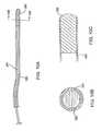
必要に応じて、本発明における分離/アクセスカテーテルは、光学画像化性能を備えられ得る。図3Eに示されるように、カテーテル本体80は、典型的には、従来の押出しプロセスによって、4個の管腔を備えるように形成され得る。管腔82は、ガイドワイヤを通過するために適切である。管腔84および86の両方は、照射のための光ファイバ88を備える。管腔90は、光学導波管またはイメージファイバ92を有する。管腔82は、典型的には、ガイドワイヤが引き出された後に、洗浄および吸引のために使用され得る。バルーンの膨張は、残りの空間、ならびに光ファイバ88を囲んでいる管腔84および86を通して行われ得る。第2のカテーテル本体100は、同軸配置の多数の別々のチューブとして形成される。外側チューブ102は、ガイドワイヤへの導入、ならびにこのガイドワイヤが取り出された後の灌流および吸引を可能にする管腔106を規定する別個のガイドワイヤチューブ104を備える。第2の内側管状部材110は、光学イメージファイバ112を有し、そして複数の光ファイバ112は、外側管状部材内の残りの空間114内を通過する。カテーテル構造80および100の両方において、光ファイバにより照射し、そしてカテーテルの遠位端のレンズを通して画像を検出することによって、前方画像化が達成され得る。この画像は、従来の陰極線または他のタイプの画像スクリーンに表示され得る。詳細には、以下に記載されるように、前方画像化により、使用者は、カテーテルを分岐した気管支を通る所望の経路を通して前進させるために、ガイドワイヤを選択的に配置し得る。
【0034】
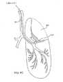
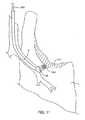
ここで図4Aを参照すると、カテーテル10は、患者の気管Tを通して、肺L内の患部領域DRまで進められ得る。気管Tを通る前進は、比較的単純であり、そして分岐した気管支を通る前進経路を選択するためにガイドワイヤを必要に応じて用いる。上記のように、ステアリングは、図3Eおよび3Fに示される画像化分離/アクセスカテーテルを使用して、リアルタイムで画像化しながら行われる。必要に応じて、分離/アクセスカテーテル10は、可視化気管チューブ(例えば、米国特許第5,285,778号に記載されるチューブ、本出願の譲渡人にライセンス提供された)を通して導入され得る。可視化気管内チューブ120は、左気管支LBおよび右気管支RBの分岐点のすぐ上の気管内で膨張される、閉鎖カフ122を備える。可視化気管内チューブ120は、前方観察光学システム(これは典型的に、左気管支LBと右気管支RBとの間の主分岐点の直接観察を可能にする照射ファイバおよびイメージファイバの両方を備える)を備える。従って、分離/アクセスカテーテルの最初の配置は、可視化気管内チューブ120および必要に応じて分離/アクセスカテーテル10自体を観察しながら行われ得る。特に4Aを再び参照して、分離/アクセスカテーテル10は、その遠位端14が、直接患部領域DRまで至る気管支内の領域に達するまで前進される。一旦配置されると、バルーン18は膨張され得、そして患部領域を含む肺組織区域が残りの肺から分離される。分離されるとは、空気または他のガスがその分離された領域と肺の残りの領域との間を任意の有意な程度まで通過しないことを意味する。
【0035】
図4Cに示されるように、組織を圧潰するために、分離/アクセスカテーテル10内の管腔に真空を付与して、分離した肺組織区域内の内部領域を吸引することが本発明の目的である。これにより、図4Cの斜線領域で示されるような圧潰された肺組織領域CLTが生じる。
【0036】
本発明によると、その分離した肺組織領域からのガスの除去を増強するために、この領域を吸引する前に様々な工程およびプロトコルが行われ得る。この領域は、過剰に膨張されるか、振動に供されるか、拡張剤または粘液溶解剤に供されるか、またはそうでなければこの領域内のガス流の障害物を除去するために処理される。これらの方法の各々は上で記載され、一般的に、分離/アクセスカテーテル10の管腔を使用する手順の少なくとも1つの局面の性能に依存している。例えば、過剰膨張は、単に分離/アクセスカテーテルを通して所望の圧力まで膨張ガスを導入することによって達成され得る。圧力は、カテーテル10の遠位先端部において変換器を使用して測定され得るが、通常は、カテーテルの近位の位置で静的に測定される。あるいはまたはさらに、吸収無気肺を誘導するために、酸素リッチなガスが分離/アクセスカテーテルを通して導入され得る。振動刺激のために、非圧縮性流体が、分離/アクセスカテーテルを通して導入され得る。刺激は、分離/アクセスカテーテルのアクセス管腔を通して導入される、外部プローブおよび/または振動カテーテルを使用して与えられ得る。
【0037】
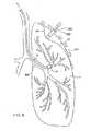
図4Dに示されるように、いくつかの例において、標的肺組織区域の吸引を増強するために、その標的区域に隣接する肺組織の膨張を減少するかまたは選択的に制御することが所望される。例えば、2分の1の肺全体が、その遠位端付近にバルーン132を有する分離または分路カテーテルによって選択的に制御され得る。このバルーンは、選択された気管支の一部分(典型的には、その領域の約60%)を閉塞するように膨張される。従って、肺内の圧力は減少され、そして肺は分離された領域以外で部分的に圧潰され得る。このようにして、標的肺組織区域の膨張は増強され得、このことはこの区域の後の吸引を妨げる他の肺内の閉塞物を破壊する際に役立ち得る。
【0038】
肺の吸引および圧潰を増強するためのこのようなインサイチュの技術に加えて、本発明は、圧潰を助ける外力の付与に依存する。図5に示されるように、針または他のカニューレ200は、壁側胸膜PPと肺胸膜VPとの間の腹膜空間PSに経皮導入され得る。二酸化炭素のような注入ガスが、シリンジまたは他の圧力源のいずれかを使用して、針200を通して導入され得る。このガスは、典型的に、自発的に呼吸している患者において、30cmH2O〜200cmH2Oの範囲の圧力まで、陽圧の通気を受けている患者において、70cmH2O〜250cmH2Oの範囲の圧力まで導入される。
【0039】
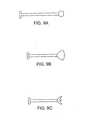
しかし、拘束されない注入ガスは特定の標的位置に配向されないため、このガスの使用は不利である。外部圧力を肺に対してより特異的に配向するために、バルーン210は、典型的には胸部トロカール212を通して胸膜腔に導入され得る。このバルーンは、透視検査に基づいて配置され得る。圧潰されるべき特定の領域に依存して、図7A〜7Dに例示されるように、様々な特定のバルーン構造が用いられ得る。シャフト220に取り付けられたほぼ球形のバルーン220が、図7Aに示される。他の構造には、翼型プロフィール(図7B)、円柱型またはスパチュラ型プロフィール(図7C)、および凸型プロフィール(図7D)が挙げられる。これらの各々は、胸膜腔への導入の後の膨張を可能にするシャフトに取り付けられる。
【0040】
針注入およびバルーン膨張に対するさらなる代替として、標的肺組織区域は、図8に示されるように、通常、胸部トロカール252を通して導入される単純なプローブ250を使用して外部から圧潰され得る。肺の外面を機械的に係合および圧縮するための様々なプローブが、図9A〜9Cに例示される。必要に応じて、標的組織肺区域内の所望の点を穿刺し、空気を放出および/または吸引するために、通常、第1のカテーテルベースの吸引の補助物として、針が使用され得る。この穿刺部は次いで、フィブリン接着剤または他の適切なシーラントで封鎖され得る。
【0041】
本発明の方法は、必要に応じて、圧潰された組織領域CLTに至る気道を封鎖または閉塞する工程を包含する。このような封鎖は、縫合、接着、エネルギー媒介性組織接着などを含む様々は方法で行われ得る。本発明の好ましい局面において、封鎖カテーテル280が、図10A〜10Cに例示されるように、プラグ282(典型的には部分的に水和されたコラーゲンヒドロゲル)を送達するために使用され得る。通常、このカテーテルは、分離/アクセスカテーテル10の主アクセス管腔を通して導入され得る寸法を有する。プラグ282は、カテーテル内の管腔の遠位先端部内に収容され、そしてプッシュロッド284はそのカテーテルの長さに伸びることにより、処置中の医師は、図11に例示されるように、そのカテーテルの先端部が適切に配置された後にプラグ282を展開し得、通常この間、分離/アクセスカテーテル上のバルーンは膨張したままであり、標的肺組織は封鎖されそして吸引し圧潰された形状のままである。一旦、肺気管支の湿環境内に展開されると、プラグ282は水を吸収し、そして圧潰された肺組織領域CLTへの気道を十分に閉塞し塞ぐために、実質的に(典型的には100%〜1000%)膨潤する。
【0042】
肺内の分離/アクセスカテーテル10の位置決めは、上記のように、オンボード光学画像化能力を使用して行われ得る。通常、分岐した気管支を通るガイドワイヤの位置決めは、分離/アクセスカテーテルの画像化要素を通して観察しながら操作される。このように、分離/アクセスカテーテルは、ガイドワイヤと分離/アクセスカテーテルを交互に前進させることによって少しずつ「寸動」され得る。分離/アクセスカテーテルに画像化を備えることの代替として、位置決めは単に蛍光透視法により行われ得る。さらなる代替として、操縦可能な画像化ガイドワイヤ300(図12A〜12C)が使用され得る。ガイドワイヤ300は、プッシュ/プルリボン304を使用して単一の平面で変形され得る変形可能な先端部302を備える。通常、この先端部は、変形を容易にするためのスプリング306を備える。操縦性に加えて、ガイドワイヤ300は、図12Cの断面図に最も良く示されるように、光学画像化導波管310および照射光ファイバ312を備える。従って、ガイドワイヤ300は、分岐した気管支を通して操縦されて、それ自体のインサイチュ画像化能力を使用して標的組織区域に到達し得る。一旦、ガイドワイヤ300が適所に配置されると、分離/アクセスカテーテルもまた標的肺組織区域に導入され得る。ガイドワイヤは画像化能力を有するため、分離/アクセスカテーテルはこのような画像化能力を組み込む必要はない。このことは有利であり得る。なぜならカテーテルがいずれの光学導波管も必要としないため、アクセス管腔がより長くなり得るからである。
【0043】
上記の方法およびデバイスに加えて、本発明の肺封鎖プロトコルは、一般に膨張可能なプラグまたはバリア、およびこの拡張可能なプラグまたはバリアに導入される接着剤を備える様々な二成分系で行われる。多くの例において、上記のような単一の拡張可能なプラグまたはバリアで十分であり得るが、他の例において、このようなプラグ/バリアを、プラグの外周の周りの封鎖、ならびにプラグ自体の表面にわたる増強された封鎖を促進し得る接着剤、シーラント、グルー(glue)、または他の同様の材料と組み合わせることが所望され得る。
【0044】
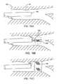
ここで図14A〜14Cを参照すると、外側シース502および内側チューブ504を備えるカテーテルシステム500が、拡張可能バリア506を送達するために使用される。図14Aに示されるように、このバリア506は、内側チューブ504の遠位端上、かつ外側シース502の管腔508内に最初に設けられる。バリア506は様々な形態を有し得るが、一般に、弾性金属、必要に応じて形状記憶合金から形成され、このバリアは、図14Bに示されるように、カテーテルアセンブリ500から放出されて肺通路LPを横切って拡張するように構成される。このバリアは、メッシュ、グリッド、膜または他の特定の構造体の形態であり得、そして肺通路LPの壁に対して係合するように構成される周縁部510を有する。必要に応じて、バリア506は、空気の通過を阻害するためにその表面にわたって取り付けられた不浸透性繊維または他の層を有し、そして/またはシーラントを含む。
【0045】
バリア506は様々な様式で送達され得るが、外側シース502を内側チューブ504上から引っ込めることにより送達され、その結果このバリア506は、シース502が回収された後に半径方向外向きに拡張することが示される。特定の実施形態において、拡張可能バリア506は肺通路LPを閉塞する、すなわちそこを通過するガスの流れを阻止するのに十分であり得るが、図14Cに示されるように、接着材料520を送達することによって閉塞を増強することが一般に好ましい。都合よくは、接着剤520は、内側チューブ504の管腔を通して導入され得る液体または他の流動性材料である。適切な材料には、好ましくは、放射線不透過性トレーサー(例えば、硝酸銀、硫酸バリウムまたは任意の他の追跡可能な生体適合性材料)と混合された、アルブミン、コラーゲンまたはフィブリンベースの合成もしくは非合成接着剤が挙げられる。接着剤は一般に硬化性であり、その結果、この接着剤は、バリア520に隣接する固体の塊を形成し、これは、特に壁に対して周囲部分510を封鎖する。
【0046】
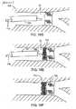
ここで図15A〜15Cを参照すると、カテーテルシステム600は、その遠位端にバルーン−拡張可能バリア604を有するカテーテル本体602を備える。カテーテル602の遠位端にあるバルーン608は、図15Bに示されるように、バリア604を拡張するために最良に使用され得る。バリア604は、様々な可鍛性材料(例えば、ステンレス鋼)から構成され得、典型的に、メッシュ、ブレード、または他の同様の構造体の形態である。必要に応じて、バリア604は、不浸透性を増強するためにそれらに積層された繊維バリアまたは膜バリアを備え得る。接着剤610は、典型的に、図15Cに示されるように、バルーンカテーテル602または必要に応じて別個の接着剤送達カテーテル612のいずれかを通して導入される。
【0047】
ここで図16A〜16Eを参照すると、本発明に従って二成分封鎖系を送達するための第3のアプローチが記載される。システム700は、その遠位端に光ファイバ可視化要素704を有するカテーテル702を備える。このカテーテル702は、閉塞される領域において、肺通路LP内に最初に配置される。次いで、図16Bに示されるように、膨潤可能なコラーゲンまたは他のプラグがカテーテル702から放出される。好ましくは、プラグ706は、プラグ706に取り付けられたままであるワイヤ708を位置決めすることによって前進され、プラグ706が伸長している間に、そのプラグ706の位置決めを可能にする。図16Cに示されるように、プラグ706が十分に拡張されそして適切に位置決めされた後、ワイヤ708が回収され得る。全ての上記の工程は、必要に応じて光ファイバー可視化要素704を使用して観察しながら達成されることが理解される。次いで、図16Dに示されるように、別個の接着剤送達チューブ710がカテーテル702を通して導入され得る。次いで、再度、好ましくは、光学観察要素704により観察されながら、接着剤712がこのチューブ710を通して送達され得る。接着剤712が導入された後、図16Fに示されるように、膨潤可能プラグ702および接着物質712を備えるバリアを適所に残して、カテーテル702および全ての関連する要素が回収され得る。
【0048】
ここで図13を参照すると、本発明に従うキット400は、少なくとも1つの分離/アクセスカテーテル10、およびIFUを使用するための使用説明書を備える。必要に応じて、このキットは上記の他のシステム要素(例えば、バルーンプローブ210、封鎖カテーテル280、薬剤容器420(必要に応じて上記の拡張剤または粘液溶解剤のいずれかを含む)、または他の要素)のいずれかをさらに備え得る。IFUを使用するための使用説明書は、上記のいずれかの方法を記載し、そして全てのキット要素は通常、ポーチ450または他の従来の医用デバイスパッケージングに一緒にパッケージングされる。通常、患者に対してこの手順を行う際に使用されるこれらのキット要素(例えば、分離/アクセスカテーテル10)は、滅菌され、キット内に滅菌維持される。必要に応じて、別個のポーチ、バッグ、トレイまたは他のパッケージングがより大きなパッケージ内に備えられ得、ここでより小さなパックが別々に開けられ得、そしてこれらの要素を滅菌様式で別々に維持し得る。
【0049】
上記は本発明の好ましい実施形態の完全な説明であるが、様々な代替物、改変物および等価物が使用され得る。従って上記記載は、添付の特許請求の範囲により規定される本発明の範囲を制限するものと理解されるべきではない。
【図面の簡単な説明】
【図1】 図1は、本発明の方法、システムおよびキットにおいて有用な、分離/アクセスカテーテルの斜視図である。
【図2】 図2は、図1のライン2に沿って取られた断面図である。
【図3】 図3A〜3Fは、図1の分離/アクセスカテーテルの代替の断面図を例示する。
【図4】 図4A〜4Cは、本発明の方法に従って標的肺組織区域を分離および圧潰するための、図1の分離/アクセスカテーテルの使用を例示する。
図4Dは、本発明に従う吸引の前に、標的肺組織区域を過剰膨張するための1つのプロトコルを例示する。
【図5】 図5は、本発明の任意の局面を例示し、ここで、注入ガスは胸膜腔からの標的区域の圧潰を助けるために導入される。
【図6】 図6は、本発明の代替の任意の局面を例示し、ここで、膨張可能バルーンは標的肺組織区域の一部分を外部から圧潰するために使用される。
【図7】 図7A〜7Dは、標的肺組織区域の外部圧潰において使用するための代替のバルーン設計を例示する。
【図8】 図8は、本発明の方法のさらに別の代替の任意の局面を例示し、ここでプローブは、標的肺組織区域の一部分を係合し圧潰するために使用され得る。
【図9】 図9A〜9Cは、代替のプローブ設計を例示する。
【図10】 図10A〜10Cは、本発明の方法、システムおよびキットにおいて使用され得る。膨潤可能な閉鎖要素を有する封鎖カテーテルを例示する。
【図11】 図11は、本発明の方法に従って、標的肺組織区域に至る空気通路を選択的に閉塞するための図10A〜10Cの封鎖カテーテルの使用を例示する。
【図12】 図12A〜12Cは、本発明の方法において使用される分離/アクセスカテーテルの位置決めを容易にするために使用され得る操縦可能な画像化ガイドワイヤを例示する。
【図13】 図13は、本発明の原理に従って構成されるキットを例示する。
【図14】 図14A〜14Cは、本発明の方法の原理に従って、機械的プラグを接着性シーラントと共に移植するための代替のカテーテルシステムの使用を例示する。
【図15】 図15A〜15Cは、機械的プラグが自己拡張性ではなくバルーンにより拡張可能であることを示す以外は、図14A〜14Cに示される方法と同様の方法を例示する。
【図16】 図16A〜16Fは、本発明に従うさらに別の例示的な方法を例示し、ここで膨潤可能なコラーゲンプラグが始めに導入され、続いて接着性シーラントがこのプラグに隣接して導入される。[0001]
(Cross-reference of related applications)
This application is a continuation-in-part of Application No. 09 / 347,032 (filed July 2, 1999, the entire disclosure of which is incorporated herein by reference).
[0002]
(Background of the Invention)
(1. Field of the Invention)
The present invention relates generally to medical methods, systems, and kits. More particularly, the present invention relates to a method and apparatus for reducing lung volume by aspirating isolated areas of lung tissue.
[0003]
Chronic obstructive pulmonary disease is an important medical problem affecting 16 million people (ie, about 6% of the US population). Specific diseases in this group include chronic bronchitis, asthmatic bronchitis, and emphysema. Many therapeutic treatments have been used and proposed, but none are fully effective and chronic obstructive pulmonary disease remains the fourth most common cause of death in the United States. Thus, improved and alternative treatments and therapies are highly beneficial.
[0004]
A particular object of the present invention is to remove lung function in patients suffering from some form of chronic obstructive pulmonary disease, typically reducing the effective lung volume, thereby removing the diseased portion of the lung. Can be improved. Ablation of the diseased part of the lung promotes the enlargement of the non-diseased area of the lung and reduces the part of the inhaled air that enters the lung but cannot transfer oxygen to the blood. Lung reduction is conventionally performed in an open or thoracoscopic procedure, where the lung is typically excised using a stapling device having an integral cutting blade.
[0005]
While effective in many cases, conventional lung reduction surgery is very traumatic for the patient, even when thoracoscopic procedures are used. Such procedures often result in unintentional removal of healthy lung tissue and frequently leave perforations or other incisions in the lung, which results in leakage of air from the remaining lungs. Even technically successful procedures can cause respiratory failure, pneumonia, and death. In addition, many elderly or susceptible patients cannot be candidates for these procedures. For these reasons, it is desirable to provide improved methods, systems, and kits for effecting lung volume reduction that overcome at least some of the disadvantages described above.
[0006]
(2. Explanation of background art)
WO 99/01076 describes devices and methods for reducing the size of lung tissue by applying heat energy to contract collagen in the lung tissue. In one embodiment, air may be removed from lung vesicles to reduce its size. The airway to the vesicle is then sealed, for example by heating, to fix the size of the vesicle. WO 98/49191 describes a plug-like device for placement in the lung airway to separate regions of lung tissue, where air is not removed from the tissue prior to embolization. WO 98/48706 describes the use of surfactants in lung lavage to treat respiratory distress syndrome.
[0007]
Patents and patent applications relating to pulmonary access, diagnosis, and treatment include: US Pat. Nos. 5,752,921; 5,707,352; 5,682,880; No. 5,660,175; No. 5,653,231; No. 5,645,519; No. 5,642,730; No. 5,598,840; No. 5,499,625 No. 5,477,851; No. 5,361,753; No. 5,331,947; No. 5,309,903; No. 5,285,778; No. 5 No. 5,143,062; No. 5,056,529; No. 4,976,710; No. 4,955,375; No. 4,961,738 No. 4,958,932; No. 4,949,716; No. 4 896,941; 4,862,874; 4,850,371; 4,846,153; 4,819,664; 4,784,133; No. 4,742,819; No. 4,716,896; No. 4,567,882; No. 4,453,545; No. 4,468,216; No. 4,327 No. 4,327,720; No. 4,041,936; No. 3,913,568; No. 3,866,599; No. 3,776,222; No. 3,677,262; No. 3,669,098; No. 3,498,286; No. 3,322,126; WO 95/33506 and WO / 9210971.
[0008]
Lung volume reduction surgery has been described in many publications, including the following: Becker et al. (1998) Am. J. et al. Respir. Crit. Care Med. 157: 1593-1599; Criner et al. (1998) Am. J. et al. Respir. Crit. Care Med. 157: 1578-1585; Kotloff et al. (1998) Chest 113: 890-895; and Ojo et al. (1997) Chest 112: 1494-1500.
[0009]
The use of mucolytic agents to clean lung occlusions is described in Sclafani (1999) AARC Times, January, 69-97. A balloon-cuffed bronchial fiberscope for reinflating lung areas suffering from refractory atelectasis is described in Harada et al. (1983) Chest 84: 725-728.
[0010]
(Summary of the Invention)
The present invention is an improved method, system, and kit for effecting lung volume reduction in patients suffering from chronic obstructive pulmonary disease or other conditions where separation of lung segments or lung volume reduction is desired. I will provide a. This method is minimally invasive and uses targets that are introduced through the mouth (intratracheal) and / or in some cases through the chest (eg thoracoscopically) Rely on separating lung tissue areas from other areas of the lung. Separation is typically accomplished by introducing a separation / access catheter into the trachea of the lungs. By positioning the distal end of the separation / access catheter within an airway that is open to the target lung tissue area, this area occludes the airway, typically within an occlusion balloon or airway on the catheter. Can be separated by inflating other structures. The target lung tissue area is then collapsed by aspirating air (and any other gas or liquid that may have been introduced) from this area, typically through the lumen of the separation / access catheter. The This suction “pressure” should be selected to be within the desired range and therefore should not be too high or too low. A preferred suction pressure is in the range of −2 mmHg to −40 mmHg, more preferably between −5 mmHg and −20 mmHg.
[0011]
Then, if desired, either the airway can be permanently blocked or the option to later tear off and widen the airway is used. Thus, this blockage can be temporary or reversible. Sealing can be accomplished by placing a plug in the airway. Suitable plugs include various mechanical and biological devices and materials. For example, various mechanical plugs can be formed from, for example, an expandable frame element and an air impermeable cover. The expandable frame element can be balloon expandable or self-expandable. Balloon expandable plugs are typically delivered by a balloon delivery catheter, while self-expandable plugs are delivered in a radially constrained state and deploy upon release of such constrains. . Other suitable mechanical plugs include check valves, which allow gas to flow outward from a separated lung area, but prevent or inhibit inward flow of gas. Exemplary biological plug materials include swellable collagen material that hydrates and swells in the airway, resulting in complete blockage of the airway. Other sealing methods include the use of tissue adhesives (eg, fibrin glue, cyanoacrylate, etc.); the use of occlusive balloons; the use of self-expanding meshes, coils and other occlusive structures; energy-induced tissue fusion (For example, use of high-frequency tissue closure); Both mechanical plugs and biological plugs can be combined with the delivery of flowable, curable sealants, adhesives, or “glues” as described in detail below. Blockage in the component system can be further enhanced.
[0012]
In a first particular aspect of the method of the invention, airflow through and from the target lung tissue area is enhanced prior to aspiration of the area. It is an object of the present invention to aspirate the lung tissue area as completely as possible and reduce the volume of the lung tissue area. In one case, the obstruction to gas flow in the target lung tissue area is reduced before or during aspiration of this area. Mucus and other obstructions in the target lung tissue area (which is diseased and often subject to obstructions) are substantially removed from this area unless removed, destroyed, or otherwise examined. Prevent complete suction. In the second case, the lack of pulmonary surfactant is the cause of the hindered airflow and the present invention provides for the administration of a suitable surfactant prior to or during aspiration of the target lung tissue area To do.
[0013]
In the first particular case, the present invention reduces gas flow obstruction by inflating the lung tissue section to a pressure higher than normal respiratory inflation pressure. If desired, the portion or area of the lung adjacent to the target lung area can be partially deflated or ventilated at the same time that the target area is inflated at a pressure higher than normal pressure. For example, airflow to adjacent lung areas can be partially blocked for low pressure in these areas, resulting in partial collapse of these areas. In certain cases, a balloon may be used to partially block the lung bronchi with the target lung tissue area.
[0014]
The isolated lung tissue area is usually 60 cmH during the administration of general anesthesia.2 O ~ 200cmH2 O range, preferably 100 cmH2 O ~ 150cmH2 Overexpanded to a pressure in the range of O (positive pressure aeration). When local anesthesia is used, the pressure is typically 10 cmH2 O ~ 100cmH2 O range, preferably 30 cmH2 O-60cmH2 O range. The duration of such “overexpansion” is typically in the range of 1 second to 600 seconds, preferably in the range of 5 seconds to 60 seconds. Such lung inflation may be repeated more than once. For example, lung inflation can be performed by expanding isolated lung tissue sections in a pulsed fashion. Overinflation was usually performed using a separation / access catheter, which was used to separate lung tissue sections. If desired, the lung region can be percutaneously inflated, typically under thoracoscopic observation, using a needle introduced through the chest.
[0015]
In the second particular case, the gas flow obstruction in the target lung tissue area is an agent that clears the obstruction and / or enlarges the airway to allow gas flow around any obstruction. Can be reduced by introducing. Exemplary agents include mucolytic agents, bronchodilators, surfactants, desiccants, solvents, carbon perfluoride, necrosis agents, adsorbents, and the like. Such agents can be introduced through the catheter, typically through a separation / access catheter used to separate the target lung tissue area. If desired, such agents can be heated to a temperature typically in the range of 38 ° C to 90 ° C to increase activity.
[0016]
In the third particular case, gas flow obstruction is reduced by delivering mechanical energy to the lung area, typically vibrational energy that destroys at least some of the obstruction. Typically, the vibration energy is ultrasonic energy, more typically ultrasonic energy having a frequency in the range of 20 kHz to 20 MHz, usually in the range of 20 kHz to 5 MHz. Mechanical energy is typically delivered to this area via an incompressible fluid that is typically introduced into the target lung tissue area through a separation / access catheter. It is understood that air is a material that transmits and absorbs very little ultrasonic energy and other vibrational energy. Thus, by introducing incompressible fluids (eg, saline, contrast agents, treatment solutions (eg, mucolytic solutions, surfactant solutions, etc.), etc., energy transfer to the entire target lung tissue area and Increase absorption. The vibrational energy is then introduced into the trachea and then through a catheter that is introduced into the target lung tissue area, or a hand-held or other ultrasonic probe intended to deliver ultrasonic energy percutaneously. It can be applied either from the outside. Typically, the vibration treatment lasts for a time in the range of 5 seconds to 60 minutes, usually in the range of 30 seconds to 30 minutes.
[0017]
In a fourth particular case, blockage of the diseased part of the lung or removal of air from these diseased parts prior to other procedures may cause these diseased parts of the lungs to move to low molecular weight gases (eg, helium or helium). And a combination of oxygen) and aeration. A technique for collapsing a region of the lung is referred to as “absorbed atelectasis,” where oxygen in the lungs can diffuse into the bloodstream. By filling the target area of the lung with pure oxygen or a high concentration of oxygen, this area of the lung is collapsed as oxygen is absorbed. Such “pure” oxygen atelectasis can be used in the methods of the invention. However, the use of pure or almost pure oxygen results in the diffusion of carbon dioxide from the bloodstream to the target lung area. Thus, complete lung collapse cannot be achieved. In contrast, the present invention preferably utilizes a low molecular weight gas (eg, helium or a combination of helium and oxygen). As described elsewhere herein, the air in the target area of the lung is completely replaced with a low molecular weight gas, and then this area is closed. Low molecular weight gases or oxygen mixtures readily diffuse into the blood and this area is collapsed with minimal carbon dioxide release from the blood to the lungs. In particular, if a pure low molecular weight gas (eg, helium) is used, the release of carbon dioxide back to the lung portion is very small, if any.
[0018]
In particularly preferred aspects, the low molecular weight gas or oxygen mixture is introduced into the lung region at a relatively low pressure with high frequency pulses. Exemplary pulse rates range from 1.5 pulses per second to 3 pulses per second at pressures ranging from 0.25 psi to 2 psi. Such “high frequency ventilation” is particularly effective in replacing the air and oxygen initially present in the lung region. If desired, the catheter used to achieve high frequency ventilation can be equipped with separate consumable ports and lumens that are connected to separate vacuum sources for proper removal of gas and low molecular weight. Replacement with a gas or oxygen mixture can be achieved.
[0019]
In a fifth particular case, removal of air from the diseased area of the lung can be enhanced by perfusion or infusion with a fluorocarbon liquid. One problem with removing gas from the diseased area of the lung is that the pulmonary passages there can be blocked with mucus and other secretions. By aerating the lung with a fluorocarbon liquid, such secretions can be removed, raising them to the top of the liquid or meniscus in the lung. Preferably, the entire lung can be treated with a fluorocarbon liquid, where the patient is mechanically ventilated. Alternatively, such treatment can be specifically directed to the diseased area of the lung immediately prior to the pneumonectomy technique described herein. This technique can be performed while a portion of the lung is being separated, typically using a separation catheter having an inflatable cuff as described anywhere herein. The fluorocarbon liquid can be introduced through the catheter, while the patient is positioned such that the liquid meniscus is preferably near the catheter when the lung portion is filled. The fluorocarbon liquid can then be removed after mucus and other secretions have been removed and surfaced to the meniscus. The lungs can then be aspirated and crushed for treatment according to other aspects of the invention.
[0020]
In a second aspect of the method of the present invention, the collapse of the target isolated lung tissue area is enhanced by applying external pressure to the isolated area. External pressure is usually applied through the chest (eg, thoracoscopically). Most simply, a safety needle can be introduced into the pleural cavity that covers the lungs, typically under the ribs (between adjacent ribs). The pleural cavity can then be insufflated (eg, carbon dioxide or other gas inflation medium introduced into the pleural cavity) to increase pressure on the lung and enhance crushing of the target area. At the same time, the target area is aspirated so that the combination of a decrease in internal pressure and an increase in external pressure acts to substantially completely collapse this area. Alternatively, external pressure can be applied by inflating the balloon within the pleural cavity that covers the target lung tissue area. Still further, external pressure can be applied by a probe that engages and is pushed against at least a portion of the external surface of the lung above the target area. If desired, using a thoracoscopic or other percutaneously placed needle, typically in combination with catheter-based aspiration as described herein. A portion of the lung can be punctured and aspirated. For example, portions of the lung that cannot be collapsed using an internal catheter can be targeted using an external needle by thoracoscopic visualization. Any puncture holes remaining in the lungs can then be sealed with a suitable adhesive (eg, a fibrin adhesive).
[0021]
In a third aspect of the present invention, a method for reducing lung volume by separating lung tissue areas and aspirating the separated areas is, for example, that the area being accessed and separated is actually diseased. Combined with a diagnostic method that makes it possible to determine whether or not and should be crushed. This diagnostic method and process can take a wide variety of forms. For example, using a separation / access catheter or other catheter introduced into the trachea to determine whether the airflow capability of the area is compromised, the airflow to the lung tissue area and the lung tissue area The airflow from can be measured. Alternatively or additionally, the separation / access catheter may be used to measure carbon dioxide concentration in the target lung tissue area. Other parameters that can be measured include forced expiration volume, pressure, pressure / volume (P / V) curves, zone compliance curves, respiratory data studies, perfusion scans, bronchiograms, and the like.
[0022]
In yet a further aspect of the method of the present invention, the target lung tissue area is separated and aspirated, wherein the area is no greater than 40% of the expanded size prior to the aspiration, usually no greater than 30%, and preferably It is crushed to a capacity of 20% or less. The inflated magnitude is its maximum magnitude at maximum inspiratory pressure, which is 40 cmH for patients undergoing positive pressure ventilation.2 Is assumed to be O, and the pressure of spontaneous breathing is 90 cmH2 O is assumed. Volume change is determined by conventional techniques (eg thoracoscopy (X-ray), CT scan, MRI, ultrasound imaging, bronchiography, PFT (pulmonary function test), gas dilution technique, etc.) Can be done.
[0023]
Such efficient collapse of the target lung tissue area can be achieved in any of the ways discussed above. Furthermore, this can be accomplished by inducing an absorbed atelectasis prior to aspiration. Most simply, absorbed atelectasis can be induced by injecting a high concentration of oxygen into a separate lung tissue area and then aspirating it. The oxygen concentration in the inlet gas should be at least 50% by volume, preferably 75% by volume, and more preferably substantially pure oxygen. Alternatively, lung collapse can be facilitated by injecting the lung with a low molecular weight gas or a combination of oxygen and low molecular weight gases, or lavage the lung with these, as generally described above. .
[0024]
The present invention further provides a system for performing an intraluminal lung volume reduction procedure in accordance with the methods of the present invention. The system includes at least one separation or access catheter having a proximal end, a distal end, an occluding element near the distal end, and at least one lumen therethrough. Separation / access catheters are typically used to establish access and separation of a target lung tissue area by intratracheal introduction into the lung airways. In the first system according to the invention, this separation / access catheter is combined with a sealing catheter carrying a closure element. The sealing catheter is adapted to be introduced through the lumen of the separation / access catheter, and the closure element is adapted to be deployed from the separation / access catheter within the airway leading to the target tissue area. The closure element typically comprises a swellable plug (eg, a partially hydrated collagen plug). Thus, deployment within the airway allows the plug to swell in situ and completely block the airway leading to the target tissue area, so that once the area is crushed, the air will block the area. Does not enter to re-inflate. Surprisingly, such occlusions have been found to substantially inhibit lung reinflation and there is little significant incidental air inflow to the collapsed area.
[0025]
In a second system according to the present invention, the separation / access catheter either cleans, dilates, or dilates the airway to facilitate substantially complete aspiration of the target tissue area. Combined with possible reagents. Exemplary reagents are described above.
[0026]
In a third system, the separation / access catheter is combined with a probe intended for percutaneous introduction to apply external pressure around the lungs. The probe may be in the form of a needle, balloon or simple engagement element intended to push the lungs inward.
[0027]
The invention still further includes a kit comprising at least one separation / access catheter as described above. The kit further includes instructions for use according to any of the methods described above. For example, the instructions can describe that the isolated lung tissue area is over-inflated to reduce the obstructions there. Alternatively, the instructions for use may state that a particular drug (as described above) is introduced into this area to break the occlusive material prior to aspiration. Still further, the kit instructions may describe that the lungs are externally collapsed by applying pressure or other external force to the area prior to or simultaneously with aspiration of the target tissue area. . Still further, the instructions may describe that the volume of the target lung tissue area is reduced by at least the percentages described above. In all cases, the kit typically further comprises a package (eg, pouch, tray, tube, box, etc.) for holding the kit components together with instructions for use. The instructions can be printed on a separate sheet (usually a package insert) and / or printed on the package itself. Usually, kit components introduced into a patient are sterilized and packaged in a sterile manner within the kit.
[0028]
(Description of specific embodiments)
Lung volume reduction is usually a target lung tissue area within the lung sub-lobal area that contains air through a single airway (ie, a branch that delivers and contains air from the alveolar area of the lung) This is done by crushing the bronchial area). Such separated lung tissue areas are first separated and then aspirated air (or other gas or liquid that may have been introduced as discussed below) from the target lung tissue area. It is crushed by. Lung tissue has a very high percentage of void volume, so the removal of internal gas is the void volume that this lung tissue has when fully inflated (ie, inflated at normal inspiration pressure). This lung tissue can be reduced to a small percentage. A typical preferred rate of this volume reduction is described above.
[0029]
In particular, the present invention provides a method and apparatus for enhancing aspiration and collapse of a target lung tissue area. Such a method and apparatus may include one or more of the following improvements. First, various approaches can be taken to remove or reduce obstacles to gas flow within the target tissue region. Second, these methods and devices can be used to apply external forces to the lungs to promote the collapse achieved by internal suction. Third, the aspiration of gas within the target tissue area can be enhanced by inducing absorptive atelectasis prior to aspiration. Absorbed atelectasis, for example, introduces oxygen-rich gas (usually at least 50% by volume oxygen, more usually at least 75% by volume oxygen, preferably substantially pure oxygen) into the lung tissue area. Can be induced. Absorption atelectasis is a phenomenon that occurs when an oxygen-rich mixture is inhaled. A high oxygen concentration causes an increase in oxygen partial pressure, which greatly increases the rate of oxygen delivery to the capillary blood in the alveolar region. This increased oxygen flux can increase so much that the net flow of gas into the blood exceeds the inspiratory flow of gas, and the lung units can become progressively smaller. Fourth, the access method and apparatus can be used as part of a normal crush procedure to perform in situ diagnostics. Any one of a number of pulmonary function characteristics can typically be measured by sampling using a separation / access catheter.
[0030]
The method of the present invention generally relies on accessing a target lung tissue area using a separation / access catheter adapted to be introduced intratracheally into the lung bronchi. An exemplary separation /
[0031]
The dimensions and materials of the separation /
[0032]
[Table 1]
[0033]
If desired, the separation / access catheter in the present invention can be equipped with optical imaging capabilities. As shown in FIG. 3E, the
[0034]
Referring now to FIG. 4A, the
[0035]
For purposes of the present invention, as shown in FIG. 4C, to collapse the tissue, a vacuum is applied to the lumen within the separation /
[0036]
In accordance with the present invention, various steps and protocols can be performed prior to aspirating this region to enhance the removal of gas from that separated lung tissue region. This region is over-expanded, subjected to vibration, subjected to a dilator or mucolytic agent, or otherwise processed to remove gas flow obstructions in this region Is done. Each of these methods is described above and generally depends on the performance of at least one aspect of the procedure using the lumen of the separation /
[0037]
As shown in FIG. 4D, in some instances, it is desirable to reduce or selectively control the expansion of lung tissue adjacent to the target area to enhance aspiration of the target lung tissue area. The For example, the entire half-lung can be selectively controlled by a separation or shunt catheter having a
[0038]
In addition to such in-situ techniques for enhancing lung aspiration and collapse, the present invention relies on the application of external forces to assist in collapse. As shown in FIG. 5, a needle or
[0039]
However, the use of this gas is disadvantageous because unconstrained injection gas is not oriented at a particular target location. In order to more orient external pressure relative to the lungs, the
[0040]
As a further alternative to needle injection and balloon inflation, the target lung tissue area can be collapsed externally using a
[0041]
The methods of the present invention include the step of blocking or occluding the airways leading to the collapsed tissue region CLT, as appropriate. Such sealing can be done in a variety of ways, including suturing, gluing, energy-mediated tissue gluing and the like. In a preferred aspect of the present invention, a sealing
[0042]
Positioning of the separation /
[0043]
In addition to the methods and devices described above, the lung closure protocol of the present invention is generally performed in a variety of two-component systems comprising an inflatable plug or barrier and an adhesive introduced into the expandable plug or barrier. In many instances, a single expandable plug or barrier as described above may be sufficient, but in other examples such plugs / barriers may be sealed around the periphery of the plug, as well as the plug itself. It may be desirable to combine with adhesives, sealants, glues, or other similar materials that can promote enhanced sealing across the surface.
[0044]
Referring now to FIGS. 14A-14C, a
[0045]
The
[0046]
Referring now to FIGS. 15A-15C, the
[0047]
Referring now to FIGS. 16A-16E, a third approach for delivering a two-component sequestration system in accordance with the present invention will be described.
[0048]
Referring now to FIG. 13, a
[0049]
While the above is a complete description of the preferred embodiments of the invention, various alternatives, modifications and equivalents may be used. Therefore, the above description should not be taken as limiting the scope of the invention which is defined by the appended claims.
[Brief description of the drawings]
FIG. 1 is a perspective view of a separation / access catheter useful in the methods, systems and kits of the present invention.
2 is a cross-sectional view taken along line 2 of FIG.
3A-3F illustrate alternative cross-sectional views of the separation / access catheter of FIG.
4A-4C illustrate the use of the separation / access catheter of FIG. 1 to separate and collapse a target lung tissue area according to the method of the present invention.
FIG. 4D illustrates one protocol for over-inflating the target lung tissue area prior to aspiration according to the present invention.
FIG. 5 illustrates an optional aspect of the present invention, where an insufflation gas is introduced to help collapse the target area from the pleural cavity.
FIG. 6 illustrates an alternative optional aspect of the present invention where an inflatable balloon is used to externally collapse a portion of the target lung tissue area.
7A-7D illustrate an alternative balloon design for use in external collapse of a target lung tissue area.
FIG. 8 illustrates yet another alternative optional aspect of the method of the present invention, where the probe can be used to engage and collapse a portion of a target lung tissue area.
9A-9C illustrate an alternative probe design.
10A-10C can be used in the methods, systems and kits of the invention. 1 illustrates a sealing catheter having a swellable closure element.
FIG. 11 illustrates the use of the closure catheter of FIGS. 10A-10C to selectively occlude air passages to a target lung tissue area according to the method of the present invention.
12A-12C illustrate a steerable imaging guidewire that can be used to facilitate positioning of a separation / access catheter used in the methods of the present invention.
FIG. 13 illustrates a kit constructed in accordance with the principles of the present invention.
FIGS. 14A-14C illustrate the use of an alternative catheter system for implanting a mechanical plug with an adhesive sealant in accordance with the principles of the method of the present invention.
FIGS. 15A-15C illustrate a method similar to that shown in FIGS. 14A-14C, except that the mechanical plug is not self-expanding and is expandable by a balloon.
FIGS. 16A-16F illustrate yet another exemplary method according to the present invention, wherein a swellable collagen plug is first introduced, followed by an adhesive sealant adjacent to the plug. Is done.
Claims (4)
Translated fromJapanese分離/アクセスカテーテルであって、近位端、遠位端、および該カテーテルを通って延びる少なくとも1つの管腔を有する、分離/アクセスカテーテル;
該分離/アクセスカテーテルに配置された膨張可能バルーン;
封鎖カテーテルであって、該分離/アクセスカテーテルの該少なくとも1つの管腔を通って送達されるように適合した、近位端、遠位端を備える、封鎖カテーテル、および
該封鎖カテーテルによって保持される閉鎖要素、
を備え、
ここで、該分離/アクセスカテーテルは、気管を通って肺気道へと、右肺または左肺の中の肺区域に供給する分岐した気管支において位置づけることができ、そして該膨張可能バルーンは、該分離/アクセスカテーテルが該肺気道を通って位置づけられているときに、該肺気道を閉塞するように膨張することができ、該封鎖カテーテルは、該分離/アクセスカテーテルの管腔を通って該肺気道内の位置へ導入され、そして該閉鎖要素は、該位置において該封鎖カテーテルから展開される、
システム。A system for performing intraluminal lung volume reduction, the system comprising:
An isolation / access catheter having a proximal end, a distal end, and at least one lumen extending therethrough;
An inflatable balloon disposed on the separation / access catheter;
A sealing catheter,comprising a proximal end, a distal end, adapted to be delivered through the at least one lumen of the separation / accesscatheter , and held bythe sealing catheter closureelements,
With
Here, the separation / access catheter can be positioned in thebranched bronchus that feeds through the trachea to the pulmonary airway and intothe lung area in the right or left lung , and the inflatable balloon is When the access catheter is positioned through the pulmonary airway, it can be inflated to occlude the pulmonary airway, the sealing catheter passing through the lumen of the isolation / access catheter And the closure element is deployed from the sealing catheter at the location;
system.
Applications Claiming Priority (3)
| Application Number | Priority Date | Filing Date | Title |
|---|---|---|---|
| US09/347,032US6287290B1 (en) | 1999-07-02 | 1999-07-02 | Methods, systems, and kits for lung volume reduction |
| US09/347,032 | 1999-07-02 | ||
| PCT/US2000/018286WO2001002042A1 (en) | 1999-07-02 | 2000-06-29 | Methods, systems, and kits for lung volume reduction |
Publications (3)
| Publication Number | Publication Date |
|---|---|
| JP2003503162A JP2003503162A (en) | 2003-01-28 |
| JP2003503162A5 JP2003503162A5 (en) | 2007-08-09 |
| JP4185283B2true JP4185283B2 (en) | 2008-11-26 |
Family
ID=23362046
Family Applications (1)
| Application Number | Title | Priority Date | Filing Date |
|---|---|---|---|
| JP2001507530AExpired - LifetimeJP4185283B2 (en) | 1999-07-02 | 2000-06-29 | Method, system and kit for lung volume reduction |
Country Status (6)
| Country | Link |
|---|---|
| US (8) | US6287290B1 (en) |
| EP (1) | EP1198269A4 (en) |
| JP (1) | JP4185283B2 (en) |
| AU (1) | AU781579B2 (en) |
| CA (1) | CA2375752A1 (en) |
| WO (1) | WO2001002042A1 (en) |
Families Citing this family (266)
| Publication number | Priority date | Publication date | Assignee | Title |
|---|---|---|---|---|
| US5868704A (en)* | 1995-09-18 | 1999-02-09 | W. L. Gore & Associates, Inc. | Balloon catheter device |
| US20060271091A1 (en)* | 1995-09-18 | 2006-11-30 | Campbell Carey V | Balloon catheter device |
| GB2324729B (en) | 1997-04-30 | 2002-01-02 | Bradford Hospitals Nhs Trust | Lung treatment device |
| US5954766A (en)* | 1997-09-16 | 1999-09-21 | Zadno-Azizi; Gholam-Reza | Body fluid flow control device |
| US6997189B2 (en)* | 1998-06-05 | 2006-02-14 | Broncus Technologies, Inc. | Method for lung volume reduction |
| US6287290B1 (en)* | 1999-07-02 | 2001-09-11 | Pulmonx | Methods, systems, and kits for lung volume reduction |
| US7422563B2 (en) | 1999-08-05 | 2008-09-09 | Broncus Technologies, Inc. | Multifunctional tip catheter for applying energy to tissue and detecting the presence of blood flow |
| US7022088B2 (en) | 1999-08-05 | 2006-04-04 | Broncus Technologies, Inc. | Devices for applying energy to tissue |
| US7175644B2 (en) | 2001-02-14 | 2007-02-13 | Broncus Technologies, Inc. | Devices and methods for maintaining collateral channels in tissue |
| US7462162B2 (en) | 2001-09-04 | 2008-12-09 | Broncus Technologies, Inc. | Antiproliferative devices for maintaining patency of surgically created channels in a body organ |
| US6749606B2 (en) | 1999-08-05 | 2004-06-15 | Thomas Keast | Devices for creating collateral channels |
| EP1400204A1 (en)* | 1999-08-05 | 2004-03-24 | Broncus Technologies, Inc. | Methods and devices for creating collateral channels in the lungs |
| US6712812B2 (en) | 1999-08-05 | 2004-03-30 | Broncus Technologies, Inc. | Devices for creating collateral channels |
| US6610043B1 (en)* | 1999-08-23 | 2003-08-26 | Bistech, Inc. | Tissue volume reduction |
| US7654998B1 (en)* | 1999-08-23 | 2010-02-02 | Aeris Therapeutics, Inc. | Tissue volume reduction |
| US6328689B1 (en) | 2000-03-23 | 2001-12-11 | Spiration, Inc., | Lung constriction apparatus and method |
| JP2003517870A (en) | 1999-12-22 | 2003-06-03 | ボストン サイエンティフィック リミテッド | Endovascular occlusion irrigation catheter and its use |
| US20030070683A1 (en)* | 2000-03-04 | 2003-04-17 | Deem Mark E. | Methods and devices for use in performing pulmonary procedures |
| US6679264B1 (en) | 2000-03-04 | 2004-01-20 | Emphasys Medical, Inc. | Methods and devices for use in performing pulmonary procedures |
| US8474460B2 (en) | 2000-03-04 | 2013-07-02 | Pulmonx Corporation | Implanted bronchial isolation devices and methods |
| US8251070B2 (en)* | 2000-03-27 | 2012-08-28 | Asthmatx, Inc. | Methods for treating airways |
| US6514290B1 (en) | 2000-03-31 | 2003-02-04 | Broncus Technologies, Inc. | Lung elastic recoil restoring or tissue compressing device and method |
| US7374532B2 (en) | 2000-04-14 | 2008-05-20 | Attenuex Technologies, Inc. | High vapor pressure attenuation device |
| US6682473B1 (en) | 2000-04-14 | 2004-01-27 | Solace Therapeutics, Inc. | Devices and methods for attenuation of pressure waves in the body |
| US10327880B2 (en) | 2000-04-14 | 2019-06-25 | Attenuex Technologies, Inc. | Attenuation device for use in an anatomical structure |
| EP1284663A4 (en)* | 2000-05-18 | 2007-04-18 | Emphasys Medical Inc | Bronchiopulmonary occlusion devices and lung volume reduction methods |
| US6722360B2 (en) | 2000-06-16 | 2004-04-20 | Rajiv Doshi | Methods and devices for improving breathing in patients with pulmonary disease |
| AU2001292609A1 (en)* | 2000-09-11 | 2002-03-26 | Closure Medical Corporation | Bronchial occlusion method and apparatus |
| US6527761B1 (en)* | 2000-10-27 | 2003-03-04 | Pulmonx, Inc. | Methods and devices for obstructing and aspirating lung tissue segments |
| US6585639B1 (en)* | 2000-10-27 | 2003-07-01 | Pulmonx | Sheath and method for reconfiguring lung viewing scope |
| US20060135947A1 (en) | 2000-10-27 | 2006-06-22 | Pulmonx | Occlusal stent and methods for its use |
| US6890343B2 (en) | 2000-12-14 | 2005-05-10 | Ensure Medical, Inc. | Plug with detachable guidewire element and methods for use |
| US6623509B2 (en) | 2000-12-14 | 2003-09-23 | Core Medical, Inc. | Apparatus and methods for sealing vascular punctures |
| US8083768B2 (en) | 2000-12-14 | 2011-12-27 | Ensure Medical, Inc. | Vascular plug having composite construction |
| US6846319B2 (en) | 2000-12-14 | 2005-01-25 | Core Medical, Inc. | Devices for sealing openings through tissue and apparatus and methods for delivering them |
| US6896692B2 (en) | 2000-12-14 | 2005-05-24 | Ensure Medical, Inc. | Plug with collet and apparatus and method for delivering such plugs |
| US20020112729A1 (en)* | 2001-02-21 | 2002-08-22 | Spiration, Inc. | Intra-bronchial obstructing device that controls biological interaction with the patient |
| US7011094B2 (en) | 2001-03-02 | 2006-03-14 | Emphasys Medical, Inc. | Bronchial flow control devices and methods of use |
| US7798147B2 (en) | 2001-03-02 | 2010-09-21 | Pulmonx Corporation | Bronchial flow control devices with membrane seal |
| US20040074491A1 (en)* | 2001-03-02 | 2004-04-22 | Michael Hendricksen | Delivery methods and devices for implantable bronchial isolation devices |
| US6609521B1 (en)* | 2001-04-09 | 2003-08-26 | Regents Of The University Of Minnesota | Endotracheal tube |
| US6577752B2 (en)* | 2001-06-15 | 2003-06-10 | Arch Development Corporation | Automated method and system for the delineation of the chest wall in computed tomography scans for the assessment of pleural disease |
| JP4602602B2 (en)* | 2001-07-19 | 2010-12-22 | オリンパス株式会社 | Medical instruments |
| JP4409123B2 (en)* | 2001-07-19 | 2010-02-03 | オリンパス株式会社 | Medical obturator |
| US6645205B2 (en)* | 2001-08-15 | 2003-11-11 | Core Medical, Inc. | Apparatus and methods for reducing lung volume |
| US7708712B2 (en) | 2001-09-04 | 2010-05-04 | Broncus Technologies, Inc. | Methods and devices for maintaining patency of surgically created channels in a body organ |
| JP4831389B2 (en)* | 2001-09-07 | 2011-12-07 | まゆみ 岡田 | Endotracheal tube |
| US7883471B2 (en)* | 2001-09-10 | 2011-02-08 | Pulmonx Corporation | Minimally invasive determination of collateral ventilation in lungs |
| US20030051733A1 (en)* | 2001-09-10 | 2003-03-20 | Pulmonx | Method and apparatus for endobronchial diagnosis |
| US20030050648A1 (en) | 2001-09-11 | 2003-03-13 | Spiration, Inc. | Removable lung reduction devices, systems, and methods |
| CA2458595C (en)* | 2001-10-11 | 2007-12-04 | Peter M. Wilson | Bronchial flow control devices and methods of use |
| US6620100B2 (en)* | 2001-10-17 | 2003-09-16 | Natus Medical Inc. | Hearing evaluation device with noise-weighting capabilities |
| US6592594B2 (en) | 2001-10-25 | 2003-07-15 | Spiration, Inc. | Bronchial obstruction device deployment system and method |
| US20030154988A1 (en)* | 2002-02-21 | 2003-08-21 | Spiration, Inc. | Intra-bronchial device that provides a medicant intra-bronchially to the patient |
| US6929637B2 (en)* | 2002-02-21 | 2005-08-16 | Spiration, Inc. | Device and method for intra-bronchial provision of a therapeutic agent |
| US20060235432A1 (en)* | 2002-02-21 | 2006-10-19 | Devore Lauri J | Intra-bronchial obstructing device that controls biological interaction with the patient |
| AU2003220124A1 (en)* | 2002-03-08 | 2003-09-22 | Emphasys Medical, Inc. | Methods and devices for inducing collapse in lung regions fed by collateral pathways |
| US20030216769A1 (en) | 2002-05-17 | 2003-11-20 | Dillard David H. | Removable anchored lung volume reduction devices and methods |
| EP2353557B1 (en)* | 2002-03-20 | 2020-05-27 | Spiration, Inc. | Removable anchored lung volume reduction devices |
| US20030181922A1 (en) | 2002-03-20 | 2003-09-25 | Spiration, Inc. | Removable anchored lung volume reduction devices and methods |
| US20030195385A1 (en)* | 2002-04-16 | 2003-10-16 | Spiration, Inc. | Removable anchored lung volume reduction devices and methods |
| US20030212412A1 (en)* | 2002-05-09 | 2003-11-13 | Spiration, Inc. | Intra-bronchial obstructing device that permits mucus transport |
| US20040089306A1 (en)* | 2002-05-28 | 2004-05-13 | Ronald Hundertmark | Devices and methods for removing bronchial isolation devices implanted in the lung |
| FR2840796B1 (en)* | 2002-06-13 | 2004-09-10 | Novatech Inc | BRONCHICAL SHUTTER |
| WO2003105676A2 (en)* | 2002-06-17 | 2003-12-24 | Bistech, Inc. | Compositions and methods for reducing lung volume |
| US7819908B2 (en)* | 2002-06-17 | 2010-10-26 | Aeris Therapeutics, Inc. | Compositions and methods for reducing lung volume |
| US20040039252A1 (en)* | 2002-06-27 | 2004-02-26 | Koch Kenneth Elmon | Self-navigating endotracheal tube |
| EP1524942B1 (en) | 2002-07-26 | 2008-09-10 | Emphasys Medical, Inc. | Bronchial flow control devices with membrane seal |
| US8123698B2 (en)* | 2002-10-07 | 2012-02-28 | Suros Surgical Systems, Inc. | System and method for minimally invasive disease therapy |
| US7814912B2 (en)* | 2002-11-27 | 2010-10-19 | Pulmonx Corporation | Delivery methods and devices for implantable bronchial isolation devices |
| US7717115B2 (en)* | 2002-11-27 | 2010-05-18 | Pulmonx Corporation | Delivery methods and devices for implantable bronchial isolation devices |
| DE10302310A1 (en)* | 2003-01-20 | 2004-07-29 | Freitag, Lutz, Dr. | Patient lung reduction method, e.g. for treating pulmonary emphysema, whereby a bronchial catheter is inserted into an over-swollen lung area and the supplying bronchopulmonary closed in synchronism with patient breathing |
| US20040210248A1 (en)* | 2003-03-12 | 2004-10-21 | Spiration, Inc. | Apparatus, method and assembly for delivery of intra-bronchial devices |
| US7100616B2 (en)* | 2003-04-08 | 2006-09-05 | Spiration, Inc. | Bronchoscopic lung volume reduction method |
| US8082921B2 (en)* | 2003-04-25 | 2011-12-27 | Anthony David Wondka | Methods, systems and devices for desufflating a lung area |
| US7811274B2 (en) | 2003-05-07 | 2010-10-12 | Portaero, Inc. | Method for treating chronic obstructive pulmonary disease |
| US20040221853A1 (en)* | 2003-05-08 | 2004-11-11 | Plasiatek, Llc | Ultrasonic placement and monitoring of a tube within the body |
| DE10321990B4 (en)* | 2003-05-15 | 2005-10-13 | Microcuff Gmbh | Trachealbeatmungungsvorrichtung |
| US7426929B2 (en) | 2003-05-20 | 2008-09-23 | Portaero, Inc. | Intra/extra-thoracic collateral ventilation bypass system and method |
| US7200559B2 (en)* | 2003-05-29 | 2007-04-03 | Microsoft Corporation | Semantic object synchronous understanding implemented with speech application language tags |
| US7533667B2 (en)* | 2003-05-29 | 2009-05-19 | Portaero, Inc. | Methods and devices to assist pulmonary decompression |
| US7252086B2 (en) | 2003-06-03 | 2007-08-07 | Cordis Corporation | Lung reduction system |
| US7377278B2 (en)* | 2003-06-05 | 2008-05-27 | Portaero, Inc. | Intra-thoracic collateral ventilation bypass system and method |
| US7682332B2 (en) | 2003-07-15 | 2010-03-23 | Portaero, Inc. | Methods to accelerate wound healing in thoracic anastomosis applications |
| US8308682B2 (en) | 2003-07-18 | 2012-11-13 | Broncus Medical Inc. | Devices for maintaining patency of surgically created channels in tissue |
| US7533671B2 (en)* | 2003-08-08 | 2009-05-19 | Spiration, Inc. | Bronchoscopic repair of air leaks in a lung |
| US20050103340A1 (en)* | 2003-08-20 | 2005-05-19 | Wondka Anthony D. | Methods, systems & devices for endobronchial ventilation and drug delivery |
| US8852229B2 (en) | 2003-10-17 | 2014-10-07 | Cordis Corporation | Locator and closure device and method of use |
| US7361183B2 (en) | 2003-10-17 | 2008-04-22 | Ensure Medical, Inc. | Locator and delivery device and method of use |
| WO2005070489A1 (en)* | 2004-01-23 | 2005-08-04 | Cook Critical Care Incorporated | Endobronchial blocking device |
| US20050178389A1 (en)* | 2004-01-27 | 2005-08-18 | Shaw David P. | Disease indications for selective endobronchial lung region isolation |
| US8206684B2 (en) | 2004-02-27 | 2012-06-26 | Pulmonx Corporation | Methods and devices for blocking flow through collateral pathways in the lung |
| US7650886B1 (en)* | 2004-03-04 | 2010-01-26 | Christian Keller | Esophageal airway management device guides |
| EP2368525B1 (en)* | 2004-03-08 | 2019-09-18 | Pulmonx, Inc | Implanted bronchial isolation devices |
| US20060081255A1 (en)* | 2004-04-02 | 2006-04-20 | Michael Miller | Ultrasonic placement and monitoring of an endotracheal tube |
| US20060037617A1 (en)* | 2004-04-19 | 2006-02-23 | Walke Amrish J | Airway implant devices and methods of use |
| NL1026190C2 (en)* | 2004-05-13 | 2005-11-15 | Peter Tjong Joe Wai | Bronchus blocker and ventilation system with bronchus blocker and ventilation tube. |
| US7530947B2 (en)* | 2004-05-28 | 2009-05-12 | Olympus Corporation | Lesion portion determining method of infrared observing system |
| US7670282B2 (en) | 2004-06-14 | 2010-03-02 | Pneumrx, Inc. | Lung access device |
| US20050281739A1 (en)* | 2004-06-16 | 2005-12-22 | Glen Gong | Imaging damaged lung tissue using compositions |
| US20050281800A1 (en)* | 2004-06-16 | 2005-12-22 | Glen Gong | Targeting sites of damaged lung tissue |
| US20050281740A1 (en)* | 2004-06-16 | 2005-12-22 | Glen Gong | Imaging damaged lung tissue |
| US20050281798A1 (en)* | 2004-06-16 | 2005-12-22 | Glen Gong | Targeting sites of damaged lung tissue using composition |
| US7678767B2 (en) | 2004-06-16 | 2010-03-16 | Pneumrx, Inc. | Glue compositions for lung volume reduction |
| US7608579B2 (en)* | 2004-06-16 | 2009-10-27 | Pneumrx, Inc. | Lung volume reduction using glue compositions |
| EP3542736A1 (en)* | 2004-06-16 | 2019-09-25 | PneumRx, Inc. | Intra-bronchial lung volume reduction system |
| US7553810B2 (en)* | 2004-06-16 | 2009-06-30 | Pneumrx, Inc. | Lung volume reduction using glue composition |
| CA2570261C (en) | 2004-07-08 | 2014-06-10 | Pneumrx, Inc. | Pleural effusion treatment device, method and material |
| US7766891B2 (en)* | 2004-07-08 | 2010-08-03 | Pneumrx, Inc. | Lung device with sealing features |
| US8409167B2 (en) | 2004-07-19 | 2013-04-02 | Broncus Medical Inc | Devices for delivering substances through an extra-anatomic opening created in an airway |
| US20060030863A1 (en)* | 2004-07-21 | 2006-02-09 | Fields Antony J | Implanted bronchial isolation device delivery devices and methods |
| US7824384B2 (en) | 2004-08-10 | 2010-11-02 | Kci Licensing, Inc. | Chest tube drainage system |
| US20060047291A1 (en)* | 2004-08-20 | 2006-03-02 | Uptake Medical Corporation | Non-foreign occlusion of an airway and lung collapse |
| US7949407B2 (en) | 2004-11-05 | 2011-05-24 | Asthmatx, Inc. | Energy delivery devices and methods |
| US20060162731A1 (en)* | 2004-11-16 | 2006-07-27 | Pulmonx | Pulmonary occlusal stent delivery catheter, loading system and methods of use |
| MX2007005937A (en) | 2004-11-16 | 2007-09-11 | Robert L Barry | Device and method for lung treatment. |
| US7771472B2 (en) | 2004-11-19 | 2010-08-10 | Pulmonx Corporation | Bronchial flow control devices and methods of use |
| US20060118126A1 (en)* | 2004-11-19 | 2006-06-08 | Don Tanaka | Methods and devices for controlling collateral ventilation |
| US7398782B2 (en) | 2004-11-19 | 2008-07-15 | Portaero, Inc. | Method for pulmonary drug delivery |
| US8220460B2 (en) | 2004-11-19 | 2012-07-17 | Portaero, Inc. | Evacuation device and method for creating a localized pleurodesis |
| WO2006058195A2 (en) | 2004-11-23 | 2006-06-01 | Pneumrx, Inc. | Steerable device for accessing a target site and methods |
| WO2006062862A1 (en)* | 2004-12-06 | 2006-06-15 | Cook Incorporated | Inflatable occlusion devices, methods, and systems |
| US8061357B2 (en) | 2004-12-08 | 2011-11-22 | Ventus Medical, Inc. | Adhesive nasal respiratory devices |
| US10610228B2 (en) | 2004-12-08 | 2020-04-07 | Theravent, Inc. | Passive nasal peep devices |
| US9833354B2 (en) | 2004-12-08 | 2017-12-05 | Theravent, Inc. | Nasal respiratory devices |
| EP1824544B1 (en) | 2004-12-08 | 2013-06-05 | Ventus Medical, Inc. | Respiratory devices and methods of use |
| US7824366B2 (en) | 2004-12-10 | 2010-11-02 | Portaero, Inc. | Collateral ventilation device with chest tube/evacuation features and method |
| US11883029B2 (en) | 2005-01-20 | 2024-01-30 | Pulmonx Corporation | Methods and devices for passive residual lung volume reduction and functional lung volume expansion |
| US8496006B2 (en) | 2005-01-20 | 2013-07-30 | Pulmonx Corporation | Methods and devices for passive residual lung volume reduction and functional lung volume expansion |
| EP1838217B1 (en)* | 2005-01-20 | 2014-06-25 | Pulmonx | Minimally invasive determination of collateral ventilation in lungs |
| US20080228137A1 (en) | 2007-03-12 | 2008-09-18 | Pulmonx | Methods and devices for passive residual lung volume reduction and functional lung volume expansion |
| US20080091062A1 (en)* | 2005-02-07 | 2008-04-17 | Smart Medical Systems, Ltd. | Endoscope assembly |
| US20070186932A1 (en)* | 2006-01-06 | 2007-08-16 | Pulmonx | Collateral pathway treatment using agent entrained by aspiration flow current |
| US8876791B2 (en) | 2005-02-25 | 2014-11-04 | Pulmonx Corporation | Collateral pathway treatment using agent entrained by aspiration flow current |
| US8153435B1 (en) | 2005-03-30 | 2012-04-10 | Tracer Detection Technology Corp. | Methods and articles for identifying objects using encapsulated perfluorocarbon tracers |
| US8088144B2 (en) | 2005-05-04 | 2012-01-03 | Ensure Medical, Inc. | Locator and closure device and method of use |
| US8926654B2 (en) | 2005-05-04 | 2015-01-06 | Cordis Corporation | Locator and closure device and method of use |
| US8287535B2 (en) | 2005-05-11 | 2012-10-16 | Mayo Foundation For Medical Education And Research | Apparatus and methods for internal surgical procedures |
| US20070142742A1 (en)* | 2005-07-13 | 2007-06-21 | Pulmonx | Methods and systems for segmental lung diagnostics |
| EP1901653A4 (en)* | 2005-07-13 | 2009-12-30 | Pulmonx | Methods and systems for segmental lung diagnostics |
| US7904144B2 (en)* | 2005-08-02 | 2011-03-08 | Brainscope Company, Inc. | Method for assessing brain function and portable automatic brain function assessment apparatus |
| US7628789B2 (en)* | 2005-08-17 | 2009-12-08 | Pulmonx Corporation | Selective lung tissue ablation |
| US8104474B2 (en) | 2005-08-23 | 2012-01-31 | Portaero, Inc. | Collateral ventilation bypass system with retention features |
| WO2007038476A2 (en) | 2005-09-26 | 2007-04-05 | Atteneux Technologies, Inc. | Pressure attenuation device |
| US8523782B2 (en) | 2005-12-07 | 2013-09-03 | Pulmonx Corporation | Minimally invasive determination of collateral ventilation in lungs |
| US7406963B2 (en) | 2006-01-17 | 2008-08-05 | Portaero, Inc. | Variable resistance pulmonary ventilation bypass valve and method |
| US8235939B2 (en) | 2006-02-06 | 2012-08-07 | Kci Licensing, Inc. | System and method for purging a reduced pressure apparatus during the administration of reduced pressure treatment |
| WO2007100846A2 (en)* | 2006-02-28 | 2007-09-07 | Emphasys Medical, Inc. | Endoscopic tool |
| US9402633B2 (en) | 2006-03-13 | 2016-08-02 | Pneumrx, Inc. | Torque alleviating intra-airway lung volume reduction compressive implant structures |
| US8888800B2 (en) | 2006-03-13 | 2014-11-18 | Pneumrx, Inc. | Lung volume reduction devices, methods, and systems |
| US8157837B2 (en) | 2006-03-13 | 2012-04-17 | Pneumrx, Inc. | Minimally invasive lung volume reduction device and method |
| US20070225809A1 (en)* | 2006-03-27 | 2007-09-27 | Ray Charles D | System and device for filling a human implantable container with a filler material |
| US7691151B2 (en) | 2006-03-31 | 2010-04-06 | Spiration, Inc. | Articulable Anchor |
| US7829986B2 (en)* | 2006-04-01 | 2010-11-09 | Stats Chippac Ltd. | Integrated circuit package system with net spacer |
| CA2955328C (en)* | 2006-05-18 | 2018-04-10 | Smart Medical Systems Ltd. | Flexible endoscope system and functionality |
| GB0610171D0 (en) | 2006-05-23 | 2006-06-28 | Robitaille Jean Pierre | Valved nasal canula |
| CA2653139C (en) | 2006-05-23 | 2016-01-05 | Ventus Medical, Inc. | Nasal respiratory devices |
| US20090145441A1 (en)* | 2007-12-06 | 2009-06-11 | Rajiv Doshi | Delayed resistance nasal devices and methods of use |
| CN101489630B (en) | 2006-06-07 | 2013-10-23 | 温吐斯医学公司 | Layered nasal devices |
| EP2032213A4 (en) | 2006-06-07 | 2014-02-19 | Theravent Inc | DEVICES FOR THE NOSE |
| US20080097139A1 (en)* | 2006-07-14 | 2008-04-24 | Boston Scientific Scimed, Inc. | Systems and methods for treating lung tissue |
| US20080140173A1 (en) | 2006-08-07 | 2008-06-12 | Sherif Eskaros | Non-shortening wrapped balloon |
| US9180279B2 (en) | 2006-08-07 | 2015-11-10 | W. L. Gore & Associates, Inc. | Inflatable imbibed polymer devices |
| US8460240B2 (en) | 2006-08-07 | 2013-06-11 | W. L. Gore & Associates, Inc. | Inflatable toroidal-shaped balloons |
| US20080125711A1 (en) | 2006-08-07 | 2008-05-29 | Alpini Alfred A | Catheter balloons with integrated non-distensible seals |
| US7785290B2 (en) | 2006-08-07 | 2010-08-31 | Gore Enterprise Holdings, Inc. | Non-shortening high angle wrapped balloons |
| DE102006039236A1 (en)* | 2006-08-21 | 2008-02-28 | Variomed Ag | Apparatus and method for reducing or removing stenoses |
| US20080072914A1 (en)* | 2006-08-25 | 2008-03-27 | Hendricksen Michael J | Bronchial Isolation Devices for Placement in Short Lumens |
| US8342182B2 (en) | 2006-08-28 | 2013-01-01 | Pulmonx Corporation | Functional assessment and treatment catheters and methods for their use in the lung |
| US8585645B2 (en)* | 2006-11-13 | 2013-11-19 | Uptake Medical Corp. | Treatment with high temperature vapor |
| US7993323B2 (en)* | 2006-11-13 | 2011-08-09 | Uptake Medical Corp. | High pressure and high temperature vapor catheters and systems |
| WO2008061252A2 (en)* | 2006-11-16 | 2008-05-22 | Ventus Medical, Inc. | Nasal devices applicators |
| US8267908B2 (en) | 2007-02-09 | 2012-09-18 | Kci Licensing, Inc. | Delivery tube, system, and method for storing liquid from a tissue site |
| WO2008100446A2 (en) | 2007-02-09 | 2008-08-21 | Kci Licensing Inc. | Apparatus and method for administering reduced pressure treatment to a tissue site |
| US20080221582A1 (en)* | 2007-03-05 | 2008-09-11 | Pulmonx | Pulmonary stent removal device |
| US8100959B2 (en)* | 2007-03-09 | 2012-01-24 | Pulmonx Corporation | Loading device for a pulmonary implant |
| US8137302B2 (en)* | 2007-03-12 | 2012-03-20 | Pulmonx Corporation | Methods and systems for occluding collateral flow channels in the lung |
| US8821376B2 (en)* | 2007-03-12 | 2014-09-02 | David Tolkowsky | Devices and methods for performing medical procedures in tree-like luminal structures |
| DE102009013205A1 (en) | 2009-03-17 | 2010-09-23 | Dolphys Technologies B.V. | Jet ventilation catheter, in particular for the ventilation of a patient |
| US8911750B2 (en)* | 2007-04-03 | 2014-12-16 | Larry W. Tsai | Lung volume reduction therapy using crosslinked biopolymers |
| US20080281151A1 (en)* | 2007-05-11 | 2008-11-13 | Portaero, Inc. | Pulmonary pleural stabilizer |
| US8163034B2 (en) | 2007-05-11 | 2012-04-24 | Portaero, Inc. | Methods and devices to create a chemically and/or mechanically localized pleurodesis |
| US7931641B2 (en) | 2007-05-11 | 2011-04-26 | Portaero, Inc. | Visceral pleura ring connector |
| US20080283065A1 (en)* | 2007-05-15 | 2008-11-20 | Portaero, Inc. | Methods and devices to maintain patency of a lumen in parenchymal tissue of the lung |
| US20080287878A1 (en)* | 2007-05-15 | 2008-11-20 | Portaero, Inc. | Pulmonary visceral pleura anastomosis reinforcement |
| US8062315B2 (en) | 2007-05-17 | 2011-11-22 | Portaero, Inc. | Variable parietal/visceral pleural coupling |
| US20080295829A1 (en)* | 2007-05-30 | 2008-12-04 | Portaero, Inc. | Bridge element for lung implant |
| US8375952B2 (en)* | 2007-08-09 | 2013-02-19 | The Nemours Foundation | Device and method for unilateral lung ventilation |
| US8607795B2 (en)* | 2007-09-20 | 2013-12-17 | Kimberly-Clark Worldwide, Inc. | Balloon cuff tracheostomy tube |
| US8043301B2 (en) | 2007-10-12 | 2011-10-25 | Spiration, Inc. | Valve loader method, system, and apparatus |
| EP2641572B1 (en) | 2007-10-12 | 2019-07-24 | Spiration Inc. | Valve loader method, system, and apparatus |
| US8322335B2 (en) | 2007-10-22 | 2012-12-04 | Uptake Medical Corp. | Determining patient-specific vapor treatment and delivery parameters |
| US8147532B2 (en) | 2007-10-22 | 2012-04-03 | Uptake Medical Corp. | Determining patient-specific vapor treatment and delivery parameters |
| JP5263765B2 (en)* | 2007-11-22 | 2013-08-14 | 国立大学法人 長崎大学 | Airway securing device |
| US8020700B2 (en) | 2007-12-05 | 2011-09-20 | Ventus Medical, Inc. | Packaging and dispensing nasal devices |
| US8882756B2 (en)* | 2007-12-28 | 2014-11-11 | Medtronic Advanced Energy Llc | Fluid-assisted electrosurgical devices, methods and systems |
| US8481845B2 (en)* | 2008-02-05 | 2013-07-09 | Gtat Corporation | Method to form a photovoltaic cell comprising a thin lamina |
| US8336540B2 (en) | 2008-02-19 | 2012-12-25 | Portaero, Inc. | Pneumostoma management device and method for treatment of chronic obstructive pulmonary disease |
| WO2009105432A2 (en) | 2008-02-19 | 2009-08-27 | Portaero, Inc. | Devices and methods for delivery of a therapeutic agent through a pneumostoma |
| US8475389B2 (en) | 2008-02-19 | 2013-07-02 | Portaero, Inc. | Methods and devices for assessment of pneumostoma function |
| JP5346922B2 (en)* | 2008-03-31 | 2013-11-20 | テルモ株式会社 | Medical obturator |
| US20100036361A1 (en)* | 2008-06-20 | 2010-02-11 | Pulmonx | System and method for delivering multiple implants into lung passageways |
| US9173669B2 (en) | 2008-09-12 | 2015-11-03 | Pneumrx, Inc. | Enhanced efficacy lung volume reduction devices, methods, and systems |
| US8444635B2 (en)* | 2008-11-19 | 2013-05-21 | Samuel Victor Lichtenstein | Methods for selectively heating tissue |
| WO2010068467A1 (en) | 2008-11-25 | 2010-06-17 | Attenuex Technologies, Inc. | Implant with high vapor pressure medium |
| CA2746525C (en) | 2008-12-31 | 2017-12-12 | Kci Licensing, Inc. | Manifolds, systems, and methods for administering reduced pressure to a subcutaneous tissue site |
| US8347881B2 (en) | 2009-01-08 | 2013-01-08 | Portaero, Inc. | Pneumostoma management device with integrated patency sensor and method |
| US8518053B2 (en) | 2009-02-11 | 2013-08-27 | Portaero, Inc. | Surgical instruments for creating a pneumostoma and treating chronic obstructive pulmonary disease |
| WO2010113305A1 (en)* | 2009-04-01 | 2010-10-07 | 株式会社アイ.エス.テイ | Tube for resolving obstructive sleep apnea syndrome |
| WO2010135352A1 (en) | 2009-05-18 | 2010-11-25 | Pneumrx, Inc. | Cross-sectional modification during deployment of an elongate lung volume reduction device |
| US8529526B2 (en) | 2009-10-20 | 2013-09-10 | Kci Licensing, Inc. | Dressing reduced-pressure indicators, systems, and methods |
| US10512761B2 (en) | 2009-12-02 | 2019-12-24 | Renovorx, Inc. | Methods for delivery of therapeutic materials to treat pancreatic cancer |
| EP2506913B8 (en) | 2009-12-02 | 2020-11-18 | RenovoRX, Inc. | Devices and kits for delivery of therapeutic materials to a pancreas |
| US9457171B2 (en) | 2009-12-02 | 2016-10-04 | Renovorx, Inc. | Devices, methods and kits for delivery of therapeutic materials to a target artery |
| US8875711B2 (en) | 2010-05-27 | 2014-11-04 | Theravent, Inc. | Layered nasal respiratory devices |
| US9592008B2 (en) | 2010-07-01 | 2017-03-14 | Pulmonx Corporation | Devices and systems for lung treatment |
| US20120053566A1 (en)* | 2010-08-25 | 2012-03-01 | Terumo Kabushiki Kaisha | Method for treatment of emphysema |
| JP2012045358A (en) | 2010-08-25 | 2012-03-08 | Terumo Corp | Therapeutic agent for pulmonary emphysema |
| US9345532B2 (en) | 2011-05-13 | 2016-05-24 | Broncus Medical Inc. | Methods and devices for ablation of tissue |
| US8795241B2 (en) | 2011-05-13 | 2014-08-05 | Spiration, Inc. | Deployment catheter |
| US8709034B2 (en) | 2011-05-13 | 2014-04-29 | Broncus Medical Inc. | Methods and devices for diagnosing, monitoring, or treating medical conditions through an opening through an airway wall |
| WO2013044267A1 (en) | 2011-09-23 | 2013-03-28 | Pulmonx, Inc. | Implant loading device and system |
| US9730830B2 (en) | 2011-09-29 | 2017-08-15 | Trudell Medical International | Nasal insert and cannula and methods for the use thereof |
| WO2013078235A1 (en) | 2011-11-23 | 2013-05-30 | Broncus Medical Inc | Methods and devices for diagnosing, monitoring, or treating medical conditions through an opening through an airway wall |
| US9821130B2 (en) | 2011-12-08 | 2017-11-21 | Avent, Inc. | Multi-diameter pediatric tracheal cuff |
| US9186053B2 (en)* | 2012-05-03 | 2015-11-17 | Covidien Lp | Methods of using light to repair hernia defects |
| WO2013188845A1 (en) | 2012-06-15 | 2013-12-19 | The Regents Of The University Of California | System and methods for lung isolation and one lung ventilation |
| US8894563B2 (en) | 2012-08-10 | 2014-11-25 | Attenuex Technologies, Inc. | Methods and systems for performing a medical procedure |
| US20140187863A1 (en)* | 2012-12-28 | 2014-07-03 | Metal Industries Research & Development Centre | Endoscope Controlling Device |
| US20140261407A1 (en)* | 2013-03-14 | 2014-09-18 | Patient Centered Medical Incorporated | Aspiration catheters, systems, and methods |
| WO2014144294A1 (en)* | 2013-03-15 | 2014-09-18 | Cook Biotech Incorporated | Methods and devices for lung volume reduction with extracellular matrix material |
| WO2014197362A1 (en) | 2013-06-03 | 2014-12-11 | Ramtin Agah | Devices, methods and kits for delivery of therapeutic materials to a pancreas |
| EP3030162B1 (en)* | 2013-08-09 | 2017-05-31 | Boston Scientific Scimed, Inc. | Devices for treating a lung |
| AU2014240225A1 (en) | 2013-10-01 | 2015-04-16 | Uptake Medical Technology Inc. | Preferential volume reduction of diseased segments of a heterogeneous lobe |
| US9968758B2 (en) | 2014-03-21 | 2018-05-15 | Boston Scientific Scimed, Inc. | Devices and methods for treating a lung |
| US10206686B2 (en) | 2014-06-10 | 2019-02-19 | Ethicon Llc | Bronchus sealants and methods of sealing bronchial tubes |
| US10390838B1 (en) | 2014-08-20 | 2019-08-27 | Pneumrx, Inc. | Tuned strength chronic obstructive pulmonary disease treatment |
| WO2016054480A2 (en)* | 2014-10-03 | 2016-04-07 | The Regent Of The University Of Colorado, A Body Corporate | Venous access catheters and methods for portal venous system catheterization |
| US10485604B2 (en) | 2014-12-02 | 2019-11-26 | Uptake Medical Technology Inc. | Vapor treatment of lung nodules and tumors |
| US10531906B2 (en) | 2015-02-02 | 2020-01-14 | Uptake Medical Technology Inc. | Medical vapor generator |
| WO2016153635A1 (en) | 2015-03-24 | 2016-09-29 | Spiration, Inc.D/B/A Olympus Respiratory America | Airway stent |
| US20160287223A1 (en)* | 2015-04-01 | 2016-10-06 | Boston Scientific Scimed, Inc. | Pulmonary biopsy devices |
| US10179008B2 (en)* | 2016-04-19 | 2019-01-15 | Lsi Solutions, Inc. | Needle assembly for pleural space insufflation and methods thereof |
| JP6761692B2 (en) | 2016-08-02 | 2020-09-30 | テルモ株式会社 | Medical device positioning method and medical device system |
| US11419490B2 (en)* | 2016-08-02 | 2022-08-23 | Covidien Lp | System and method of using an endoscopic catheter as a port in laparoscopic surgery |
| WO2018027145A1 (en)* | 2016-08-04 | 2018-02-08 | Shifamed Holdings, Llc | Devices and methods for lung volume reduction |
| US10448886B2 (en)* | 2016-08-17 | 2019-10-22 | Covidien Lp | Induced atelectasis and pulmonary consolidation systems and methods |
| WO2018060848A1 (en) | 2016-09-30 | 2018-04-05 | Pneumrx Inc. | Guidewire |
| GB2558920A (en)* | 2017-01-20 | 2018-07-25 | Cook Medical Technologies Llc | Aneurysm treatment apparatus |
| EP3606457A4 (en) | 2017-04-03 | 2021-04-21 | Broncus Medical Inc. | ELECTROSURGICAL ACCESS SHEATH |
| US11129673B2 (en) | 2017-05-05 | 2021-09-28 | Uptake Medical Technology Inc. | Extra-airway vapor ablation for treating airway constriction in patients with asthma and COPD |
| US11052224B2 (en) | 2017-05-18 | 2021-07-06 | Renovorx, Inc. | Methods for treating cancerous tumors |
| US10695543B2 (en) | 2017-05-18 | 2020-06-30 | Renovorx, Inc. | Methods for treating cancerous tumors |
| US12290564B2 (en) | 2017-05-18 | 2025-05-06 | Renovorx, Inc. | Methods and apparatuses for treating tumors |
| US11344364B2 (en) | 2017-09-07 | 2022-05-31 | Uptake Medical Technology Inc. | Screening method for a target nerve to ablate for the treatment of inflammatory lung disease |
| US11350988B2 (en) | 2017-09-11 | 2022-06-07 | Uptake Medical Technology Inc. | Bronchoscopic multimodality lung tumor treatment |
| USD845467S1 (en) | 2017-09-17 | 2019-04-09 | Uptake Medical Technology Inc. | Hand-piece for medical ablation catheter |
| US11419658B2 (en) | 2017-11-06 | 2022-08-23 | Uptake Medical Technology Inc. | Method for treating emphysema with condensable thermal vapor |
| US20210169632A1 (en)* | 2017-12-01 | 2021-06-10 | Eolo Medical Inc. | Methods and devices for trans-bronchial airway bypass |
| US11490946B2 (en) | 2017-12-13 | 2022-11-08 | Uptake Medical Technology Inc. | Vapor ablation handpiece |
| CA3100063A1 (en) | 2018-04-17 | 2019-10-24 | The Board Of Trustees Of The Leland Stanford Junior University | Airway visualization system |
| WO2020163625A1 (en) | 2019-02-07 | 2020-08-13 | Solace Therapeutics, Inc. | Pressure attenuation device |
| US11653927B2 (en) | 2019-02-18 | 2023-05-23 | Uptake Medical Technology Inc. | Vapor ablation treatment of obstructive lung disease |
| EP3917426B1 (en)* | 2019-06-20 | 2023-09-06 | Axon Therapies, Inc. | Devices for endovascular ablation of a splanchnic nerve |
| CN115003231B (en)* | 2019-12-03 | 2025-09-19 | 波士顿科学国际有限公司 | Medical delivery device and method of use |
| US20220404055A1 (en)* | 2021-06-16 | 2022-12-22 | United States Of America As Represented By The Secretary Of The Army | Bioprotection of transportion and facilities using lumped element model |
Family Cites Families (73)
| Publication number | Priority date | Publication date | Assignee | Title |
|---|---|---|---|---|
| US1906678A (en)* | 1931-06-09 | 1933-05-02 | Reinhold H Wappler | Plugging device for catheters |
| AT244495B (en) | 1963-04-19 | 1966-01-10 | Willy Ruesch Fa | Catheters for ventilation and / or anesthesia |
| US3498286A (en) | 1966-09-21 | 1970-03-03 | American Optical Corp | Catheters |
| US3669098A (en) | 1968-10-05 | 1972-06-13 | Olympus Optical Co | Endotracheal tube |
| US3677262A (en) | 1970-07-23 | 1972-07-18 | Henry J Zukowski | Surgical instrument illuminating endotracheal tube inserter |
| US3776222A (en) | 1971-12-23 | 1973-12-04 | Lurosso A | Fiber optic entubator and method of entubation of the trachea through the nasopharynx |
| US3866599A (en) | 1972-01-21 | 1975-02-18 | Univ Washington | Fiberoptic catheter |
| US3913568A (en) | 1973-01-22 | 1975-10-21 | American Optical Corp | Nasopharyngoscope |
| US4041936A (en) | 1975-04-23 | 1977-08-16 | Medical Engineering Corporation | Bronchoscopy tube |
| US4086919A (en) | 1976-07-09 | 1978-05-02 | Bullard James R | Laryngoscope |
| US4327721A (en) | 1978-07-07 | 1982-05-04 | George Hanover | Endotracheal tube with topical agent delivery system and method of using the same |
| US4327720A (en) | 1979-01-22 | 1982-05-04 | Bronson Paul A | Esophageal-endotracheal airway |
| JPS6010740B2 (en) | 1981-05-07 | 1985-03-19 | 宏司 井上 | Endotracheal tube for unilateral lung ventilation |
| US4445892A (en)* | 1982-05-06 | 1984-05-01 | Laserscope, Inc. | Dual balloon catheter device |
| US4468216A (en) | 1982-05-20 | 1984-08-28 | Rudolph Muto | Irrigation suction catheter |
| US4567882A (en) | 1982-12-06 | 1986-02-04 | Vanderbilt University | Method for locating the illuminated tip of an endotracheal tube |
| WO1986002845A1 (en) | 1984-11-15 | 1986-05-22 | Stefano Nazari | Device for selective bronchial intubation and separate lung ventilation |
| JPS61250605A (en) | 1985-04-27 | 1986-11-07 | Power Reactor & Nuclear Fuel Dev Corp | Image fiber with optical waveguide |
| IT8629545V0 (en)* | 1986-06-12 | 1986-06-12 | Fina Ernesto | SET BALLOON URETERAL CATHETER BALLOON FOR EXTRACTION OF URETERAL STONES |
| US4716896A (en) | 1986-08-01 | 1988-01-05 | Ackrad Laboratories | Bronchial catheter |
| US4976710A (en) | 1987-01-28 | 1990-12-11 | Mackin Robert A | Working well balloon method |
| US4961738A (en) | 1987-01-28 | 1990-10-09 | Mackin Robert A | Angioplasty catheter with illumination and visualization within angioplasty balloon |
| US4784133A (en) | 1987-01-28 | 1988-11-15 | Mackin Robert A | Working well balloon angioscope and method |
| US4742819A (en) | 1987-03-23 | 1988-05-10 | George Gordon P | Intubating scope with camera and screen |
| DE3719250A1 (en) | 1987-06-10 | 1988-12-22 | Kellner Hans Joerg Dr Med | ENDOSCOPE |
| US6013619A (en) | 1988-01-06 | 2000-01-11 | The Scripps Research Institute | Pulmonary surfactants and therapeutic uses, including pulmonary lavage |
| US4846153A (en) | 1988-06-10 | 1989-07-11 | George Berci | Intubating video endoscope |
| US4850371A (en) | 1988-06-13 | 1989-07-25 | Broadhurst John H | Novel endotracheal tube and mass spectrometer |
| US4958932A (en) | 1988-08-18 | 1990-09-25 | Mcdonnell Douglas Corporation | Optical measuring apparatus |
| US4949716A (en) | 1988-10-31 | 1990-08-21 | Medical Devices, Inc. | Nasal intubation adjunct |
| US4955375A (en) | 1989-01-23 | 1990-09-11 | Ricardo Martinez | Endotracheal tube with channel for delivering drugs |
| US5562608A (en) | 1989-08-28 | 1996-10-08 | Biopulmonics, Inc. | Apparatus for pulmonary delivery of drugs with simultaneous liquid lavage and ventilation |
| US5019039A (en)* | 1989-11-15 | 1991-05-28 | Anderson Ronald W | Fluid drainage needle method of use |
| US5207220A (en) | 1989-12-12 | 1993-05-04 | Burroughs Wellcome Co. | Method for administering pharmaceuticals, including liquid surfactant, to the lungs |
| US5146916A (en) | 1990-01-05 | 1992-09-15 | Catalani Angelo S | Endotracheal tube incorporating a drug-irrigation device |
| US5056529A (en) | 1990-04-03 | 1991-10-15 | Groot William J De | Apparatus and method for performing a transbroncheal biopsy |
| US5143062A (en) | 1990-10-26 | 1992-09-01 | Mallinckrodt Medical, Inc. | Endotracheal tube having irrigation means |
| US5165420A (en)* | 1990-12-21 | 1992-11-24 | Ballard Medical Products | Bronchoalveolar lavage catheter |
| US5246012A (en) | 1990-12-21 | 1993-09-21 | Ballard Medical Products | Bronchoalveolar lavage catheter |
| US5285778A (en) | 1991-04-19 | 1994-02-15 | Mackin Robert A | Endotracheal tube wih fibers optic illumination and viewing and auxiliary tube |
| US5370134A (en)* | 1991-05-29 | 1994-12-06 | Orgin Medsystems, Inc. | Method and apparatus for body structure manipulation and dissection |
| US5258042A (en)* | 1991-12-16 | 1993-11-02 | Henry Ford Health System | Intravascular hydrogel implant |
| US5174323A (en)* | 1992-03-02 | 1992-12-29 | Kent Haselden | Liquid material reservoir |
| US5331947A (en) | 1992-05-01 | 1994-07-26 | Shturman Cardiology Systems, Inc. | Inflatable sheath for introduction of ultrasonic catheter through the lumen of a fiber optic endoscope |
| DE4222220A1 (en) | 1992-07-07 | 1994-01-13 | Deutsche Aerospace | Procedure for measuring and regulating the pressure in the sealing sleeve of a tracheal tube |
| US5400771A (en) | 1993-01-21 | 1995-03-28 | Pirak; Leon | Endotracheal intubation assembly and related method |
| US5499625A (en) | 1994-01-27 | 1996-03-19 | The Kendall Company | Esophageal-tracheal double lumen airway |
| US5471851A (en) | 1994-03-15 | 1995-12-05 | Zakryk; John M. | Self-regulating swimming pool heater unit |
| US5645519A (en) | 1994-03-18 | 1997-07-08 | Jai S. Lee | Endoscopic instrument for controlled introduction of tubular members in the body and methods therefor |
| GB9411215D0 (en) | 1994-06-04 | 1994-07-27 | Brain Archibald Ian Jeremy | A fibreoptic intubating laryngeal mask airway |
| US5642730A (en) | 1994-06-17 | 1997-07-01 | Trudell Medical Limited | Catheter system for delivery of aerosolized medicine for use with pressurized propellant canister |
| US5583114A (en)* | 1994-07-27 | 1996-12-10 | Minnesota Mining And Manufacturing Company | Adhesive sealant composition |
| US5477851A (en) | 1995-01-26 | 1995-12-26 | Callaghan; Eric B. | Laryngeal mask assembly and method for removing same |
| US5598840A (en) | 1995-03-17 | 1997-02-04 | Sorenson Critical Care, Inc. | Apparatus and method for ventilation and aspiration |
| US5588424A (en)* | 1995-06-28 | 1996-12-31 | The Cleveland Clinic Foundation | Bronchial blocker endotracheal apparatus |
| US5660175A (en) | 1995-08-21 | 1997-08-26 | Dayal; Bimal | Endotracheal device |
| US5722990A (en)* | 1995-11-08 | 1998-03-03 | Sugar Surgical Technologies, Inc. | Tissue grasping device |
| US5653231A (en) | 1995-11-28 | 1997-08-05 | Medcare Medical Group, Inc. | Tracheostomy length single use suction catheter |
| DE19547538C2 (en)* | 1995-12-20 | 1999-09-23 | Ruesch Willy Ag | Instrument for use in interventional flexible tracheoscopy / bronchoscopy |
| US5752921A (en) | 1996-01-11 | 1998-05-19 | Korr Medical Technologies, Inc. | Method and apparatus for determining tracheal pressure |
| US5904648A (en)* | 1996-06-18 | 1999-05-18 | Cook Incorporated | Guided endobronchial blocker catheter |
| US5682880A (en) | 1996-07-26 | 1997-11-04 | Brain; Archibald Ian Jeremy | Laryngeal-mask airway with guide element, stiffener, and fiberoptic access |
| US5893841A (en) | 1996-08-30 | 1999-04-13 | Delcath Systems, Inc. | Balloon catheter with occluded segment bypass |
| GB2324729B (en) | 1997-04-30 | 2002-01-02 | Bradford Hospitals Nhs Trust | Lung treatment device |
| US5957919A (en) | 1997-07-02 | 1999-09-28 | Laufer; Michael D. | Bleb reducer |
| US5954636A (en)* | 1997-07-15 | 1999-09-21 | Schwartz; Roy E. | Pediatric endotracheal tube with bronchial blocker and method for selectively blocking respiratory airflow to a pediatric patient's lung |
| US6077258A (en) | 1997-10-03 | 2000-06-20 | Scimed Life Systems, Inc. | Braided angiography catheter having full length radiopacity and controlled flexibility |
| US6099481A (en)* | 1997-11-03 | 2000-08-08 | Ntc Technology, Inc. | Respiratory profile parameter determination method and apparatus |
| US5897528A (en) | 1998-04-30 | 1999-04-27 | Medtronic, Inc. | Filtered intracerebroventricular or intraspinal access port with direct cerebrospinal fluid access |
| US6493589B1 (en) | 1998-05-07 | 2002-12-10 | Medtronic, Inc. | Methods and apparatus for treatment of pulmonary conditions |
| US6174323B1 (en) | 1998-06-05 | 2001-01-16 | Broncus Technologies, Inc. | Method and assembly for lung volume reduction |
| US6287290B1 (en) | 1999-07-02 | 2001-09-11 | Pulmonx | Methods, systems, and kits for lung volume reduction |
| US6293951B1 (en) | 1999-08-24 | 2001-09-25 | Spiration, Inc. | Lung reduction device, system, and method |
- 1999
- 1999-07-02USUS09/347,032patent/US6287290B1/ennot_activeExpired - Lifetime
- 2000
- 2000-06-28USUS09/606,320patent/US6878141B1/ennot_activeExpired - Lifetime
- 2000-06-29JPJP2001507530Apatent/JP4185283B2/ennot_activeExpired - Lifetime
- 2000-06-29AUAU59109/00Apatent/AU781579B2/ennot_activeExpired
- 2000-06-29WOPCT/US2000/018286patent/WO2001002042A1/enactiveIP Right Grant
- 2000-06-29CACA002375752Apatent/CA2375752A1/ennot_activeAbandoned
- 2000-06-29EPEP00945122Apatent/EP1198269A4/ennot_activeWithdrawn
- 2001
- 2001-07-02USUS09/898,703patent/US6709401B2/ennot_activeExpired - Lifetime
- 2001-12-13USUS10/017,068patent/US7141046B2/ennot_activeExpired - Lifetime
- 2004
- 2004-01-26USUS10/765,380patent/US7186259B2/ennot_activeExpired - Lifetime
- 2004-08-20USUS10/923,109patent/US7458963B2/ennot_activeExpired - Lifetime
- 2005
- 2005-04-12USUS11/104,717patent/US7766895B2/ennot_activeExpired - Lifetime
- 2010
- 2010-06-22USUS12/820,402patent/US8177769B2/ennot_activeExpired - Fee Related
Also Published As
| Publication number | Publication date |
|---|---|
| EP1198269A1 (en) | 2002-04-24 |
| US7186259B2 (en) | 2007-03-06 |
| US20020062120A1 (en) | 2002-05-23 |
| US6709401B2 (en) | 2004-03-23 |
| US6287290B1 (en) | 2001-09-11 |
| CA2375752A1 (en) | 2001-01-11 |
| JP2003503162A (en) | 2003-01-28 |
| US20040158228A1 (en) | 2004-08-12 |
| AU5910900A (en) | 2001-01-22 |
| US7458963B2 (en) | 2008-12-02 |
| US7141046B2 (en) | 2006-11-28 |
| US8177769B2 (en) | 2012-05-15 |
| US20010056274A1 (en) | 2001-12-27 |
| WO2001002042A1 (en) | 2001-01-11 |
| US20050015106A1 (en) | 2005-01-20 |
| US20100280538A1 (en) | 2010-11-04 |
| EP1198269A4 (en) | 2009-10-21 |
| AU781579B2 (en) | 2005-06-02 |
| US7766895B2 (en) | 2010-08-03 |
| US20050203483A1 (en) | 2005-09-15 |
| US6878141B1 (en) | 2005-04-12 |
Similar Documents
| Publication | Publication Date | Title |
|---|---|---|
| JP4185283B2 (en) | Method, system and kit for lung volume reduction | |
| WO2001002042A9 (en) | Methods, systems, and kits for lung volume reduction | |
| US6997918B2 (en) | Methods and devices for obstructing and aspirating lung tissue segments | |
| US8079368B2 (en) | Bronchoscopic lung volume reduction method | |
| AU2004263132B2 (en) | Bronchoscopic repair of air leaks in a lung | |
| US7662181B2 (en) | Methods and devices for use in performing pulmonary procedures | |
| US8137302B2 (en) | Methods and systems for occluding collateral flow channels in the lung |
Legal Events
| Date | Code | Title | Description |
|---|---|---|---|
| A521 | Request for written amendment filed | Free format text:JAPANESE INTERMEDIATE CODE: A523 Effective date:20070618 | |
| A621 | Written request for application examination | Free format text:JAPANESE INTERMEDIATE CODE: A621 Effective date:20070618 | |
| A131 | Notification of reasons for refusal | Free format text:JAPANESE INTERMEDIATE CODE: A131 Effective date:20071115 | |
| A521 | Request for written amendment filed | Free format text:JAPANESE INTERMEDIATE CODE: A523 Effective date:20080123 | |
| A02 | Decision of refusal | Free format text:JAPANESE INTERMEDIATE CODE: A02 Effective date:20080221 | |
| A521 | Request for written amendment filed | Free format text:JAPANESE INTERMEDIATE CODE: A523 Effective date:20080619 | |
| A911 | Transfer to examiner for re-examination before appeal (zenchi) | Free format text:JAPANESE INTERMEDIATE CODE: A911 Effective date:20080811 | |
| TRDD | Decision of grant or rejection written | ||
| A01 | Written decision to grant a patent or to grant a registration (utility model) | Free format text:JAPANESE INTERMEDIATE CODE: A01 Effective date:20080822 | |
| A01 | Written decision to grant a patent or to grant a registration (utility model) | Free format text:JAPANESE INTERMEDIATE CODE: A01 | |
| A61 | First payment of annual fees (during grant procedure) | Free format text:JAPANESE INTERMEDIATE CODE: A61 Effective date:20080905 | |
| FPAY | Renewal fee payment (event date is renewal date of database) | Free format text:PAYMENT UNTIL: 20110912 Year of fee payment:3 | |
| R150 | Certificate of patent or registration of utility model | Ref document number:4185283 Country of ref document:JP Free format text:JAPANESE INTERMEDIATE CODE: R150 Free format text:JAPANESE INTERMEDIATE CODE: R150 | |
| FPAY | Renewal fee payment (event date is renewal date of database) | Free format text:PAYMENT UNTIL: 20120912 Year of fee payment:4 | |
| R250 | Receipt of annual fees | Free format text:JAPANESE INTERMEDIATE CODE: R250 | |
| FPAY | Renewal fee payment (event date is renewal date of database) | Free format text:PAYMENT UNTIL: 20130912 Year of fee payment:5 | |
| R250 | Receipt of annual fees | Free format text:JAPANESE INTERMEDIATE CODE: R250 | |
| R250 | Receipt of annual fees | Free format text:JAPANESE INTERMEDIATE CODE: R250 | |
| R250 | Receipt of annual fees | Free format text:JAPANESE INTERMEDIATE CODE: R250 | |
| R250 | Receipt of annual fees | Free format text:JAPANESE INTERMEDIATE CODE: R250 | |
| R250 | Receipt of annual fees | Free format text:JAPANESE INTERMEDIATE CODE: R250 | |
| R250 | Receipt of annual fees | Free format text:JAPANESE INTERMEDIATE CODE: R250 | |
| R250 | Receipt of annual fees | Free format text:JAPANESE INTERMEDIATE CODE: R250 | |
| R250 | Receipt of annual fees | Free format text:JAPANESE INTERMEDIATE CODE: R250 | |
| EXPY | Cancellation because of completion of term |