JP4185165B2 - Vascular wound closure device - Google Patents
Vascular wound closure deviceDownload PDFInfo
- Publication number
- JP4185165B2 JP4185165B2JP52151197AJP52151197AJP4185165B2JP 4185165 B2JP4185165 B2JP 4185165B2JP 52151197 AJP52151197 AJP 52151197AJP 52151197 AJP52151197 AJP 52151197AJP 4185165 B2JP4185165 B2JP 4185165B2
- Authority
- JP
- Japan
- Prior art keywords
- retractor
- dilator
- distal end
- hollow
- cap
- Prior art date
- Legal status (The legal status is an assumption and is not a legal conclusion. Google has not performed a legal analysis and makes no representation as to the accuracy of the status listed.)
- Expired - Lifetime
Links
- 230000002792vascularEffects0.000titleclaimsdescription5
- 210000001105femoral arteryAnatomy0.000claimsdescription59
- 210000005166vasculatureAnatomy0.000claimsdescription39
- 210000004204blood vesselAnatomy0.000claimsdescription16
- 210000004369bloodAnatomy0.000claimsdescription10
- 239000008280bloodSubstances0.000claimsdescription10
- -1polypropylenePolymers0.000claimsdescription8
- 229920001971elastomerPolymers0.000claimsdescription5
- 239000000806elastomerSubstances0.000claimsdescription5
- 229910052751metalInorganic materials0.000claimsdescription5
- 239000002184metalSubstances0.000claimsdescription5
- 229920000642polymerPolymers0.000claimsdescription5
- 239000004698PolyethyleneSubstances0.000claimsdescription4
- 239000004743PolypropyleneSubstances0.000claimsdescription4
- 229920000573polyethylenePolymers0.000claimsdescription4
- 229920001155polypropylenePolymers0.000claimsdescription4
- 206010052428WoundDiseases0.000description66
- 208000027418Wounds and injuryDiseases0.000description66
- 238000000034methodMethods0.000description38
- 210000001367arteryAnatomy0.000description17
- 238000002399angioplastyMethods0.000description13
- 238000002583angiographyMethods0.000description9
- 230000000740bleeding effectEffects0.000description5
- 238000009958sewingMethods0.000description4
- 208000031481Pathologic ConstrictionDiseases0.000description3
- 206010041899Stab woundDiseases0.000description3
- 230000017531blood circulationEffects0.000description3
- 238000002405diagnostic procedureMethods0.000description3
- 230000004048modificationEffects0.000description3
- 238000012986modificationMethods0.000description3
- 229910001220stainless steelInorganic materials0.000description3
- 239000010935stainless steelSubstances0.000description3
- 208000037804stenosisDiseases0.000description3
- 230000036262stenosisEffects0.000description3
- 239000002872contrast mediaSubstances0.000description2
- 230000010339dilationEffects0.000description2
- 238000003384imaging methodMethods0.000description2
- 238000003780insertionMethods0.000description2
- 230000037431insertionEffects0.000description2
- 230000004807localizationEffects0.000description2
- 230000007774longtermEffects0.000description2
- 238000012544monitoring processMethods0.000description2
- 230000002966stenotic effectEffects0.000description2
- 238000001356surgical procedureMethods0.000description2
- 238000002560therapeutic procedureMethods0.000description2
- 206010011086Coronary artery occlusionDiseases0.000description1
- 229920000742CottonPolymers0.000description1
- 208000018262Peripheral vascular diseaseDiseases0.000description1
- RTAQQCXQSZGOHL-UHFFFAOYSA-NTitaniumChemical compound[Ti]RTAQQCXQSZGOHL-UHFFFAOYSA-N0.000description1
- 239000011324beadSubstances0.000description1
- 229920000249biocompatible polymerPolymers0.000description1
- 230000002612cardiopulmonary effectEffects0.000description1
- 238000007887coronary angioplastyMethods0.000description1
- 201000010099diseaseDiseases0.000description1
- 208000037265diseases, disorders, signs and symptomsDiseases0.000description1
- 238000006073displacement reactionMethods0.000description1
- 210000003414extremityAnatomy0.000description1
- 239000000835fiberSubstances0.000description1
- 238000002695general anesthesiaMethods0.000description1
- 210000003709heart valveAnatomy0.000description1
- 210000003090iliac arteryAnatomy0.000description1
- 230000002045lasting effectEffects0.000description1
- 238000012806monitoring deviceMethods0.000description1
- 239000004033plasticSubstances0.000description1
- 229920003023plasticPolymers0.000description1
- 229920001296polysiloxanePolymers0.000description1
- 239000011148porous materialSubstances0.000description1
- 238000003825pressingMethods0.000description1
- 238000011084recoveryMethods0.000description1
- 230000000250revascularizationEffects0.000description1
- 238000000926separation methodMethods0.000description1
- 229920000260silasticPolymers0.000description1
- 229910000811surgical stainless steelInorganic materials0.000description1
- 210000000779thoracic wallAnatomy0.000description1
- 239000010936titaniumSubstances0.000description1
- 229910052719titaniumInorganic materials0.000description1
- 230000007704transitionEffects0.000description1
- 230000000472traumatic effectEffects0.000description1
- 210000000689upper legAnatomy0.000description1
Images


Classifications
- A—HUMAN NECESSITIES
- A61—MEDICAL OR VETERINARY SCIENCE; HYGIENE
- A61B—DIAGNOSIS; SURGERY; IDENTIFICATION
- A61B17/00—Surgical instruments, devices or methods
- A61B17/02—Surgical instruments, devices or methods for holding wounds open, e.g. retractors; Tractors
- A61B17/0206—Surgical instruments, devices or methods for holding wounds open, e.g. retractors; Tractors with antagonistic arms as supports for retractor elements
- A—HUMAN NECESSITIES
- A61—MEDICAL OR VETERINARY SCIENCE; HYGIENE
- A61B—DIAGNOSIS; SURGERY; IDENTIFICATION
- A61B17/00—Surgical instruments, devices or methods
- A61B17/0057—Implements for plugging an opening in the wall of a hollow or tubular organ, e.g. for sealing a vessel puncture or closing a cardiac septal defect
- A—HUMAN NECESSITIES
- A61—MEDICAL OR VETERINARY SCIENCE; HYGIENE
- A61B—DIAGNOSIS; SURGERY; IDENTIFICATION
- A61B17/00—Surgical instruments, devices or methods
- A61B17/12—Surgical instruments, devices or methods for ligaturing or otherwise compressing tubular parts of the body, e.g. blood vessels or umbilical cord
- A61B17/128—Surgical instruments, devices or methods for ligaturing or otherwise compressing tubular parts of the body, e.g. blood vessels or umbilical cord for applying or removing clamps or clips
- B—PERFORMING OPERATIONS; TRANSPORTING
- B29—WORKING OF PLASTICS; WORKING OF SUBSTANCES IN A PLASTIC STATE IN GENERAL
- B29K—INDEXING SCHEME ASSOCIATED WITH SUBCLASSES B29B, B29C OR B29D, RELATING TO MOULDING MATERIALS OR TO MATERIALS FOR MOULDS, REINFORCEMENTS, FILLERS OR PREFORMED PARTS, e.g. INSERTS
- B29K2067/00—Use of polyesters or derivatives thereof, as moulding material
- B29K2067/003—PET, i.e. poylethylene terephthalate
Landscapes
- Health & Medical Sciences (AREA)
- Life Sciences & Earth Sciences (AREA)
- Surgery (AREA)
- Heart & Thoracic Surgery (AREA)
- Engineering & Computer Science (AREA)
- Biomedical Technology (AREA)
- Nuclear Medicine, Radiotherapy & Molecular Imaging (AREA)
- Medical Informatics (AREA)
- Molecular Biology (AREA)
- Animal Behavior & Ethology (AREA)
- General Health & Medical Sciences (AREA)
- Public Health (AREA)
- Veterinary Medicine (AREA)
- Surgical Instruments (AREA)
Description
Translated fromJapanese発明の分野
本発明は患者の血管構造における刺し傷または他の創傷の閉鎖を助成する装置に関する。詳細には、本発明は血管構造における穴の位置を見つけ、この穴を隔絶し、適切な創傷閉鎖装置をその箇所へ案内して、外科クリップ、縫い糸またはステープルを使用して創傷を閉じるように助成する血管創傷閉鎖装置に関する。
発明の背景
手足における著しく狭くなった動脈を通る血液の流れを増大したり、復帰させたりする末梢血管疾患の治療に、経管腔バルーン血管形成法が使用されており、この経管腔バルーン血管形成法は冠状動脈の閉塞の治療にも使用されている。実際、冠状血管形成は狭窄性および閉塞冠状動脈の血管再新生のためのバイパス手術に対する主な実行可能変更例として出現した。バイパス手術とは違って、血管形成法は一般の麻酔、胸壁部の開口、心−肺機械の使用、または輸血を必要としない。血管形成法は患者に対してさほど侵略的でも、外傷的でもないだけではなく、短い病院滞在および短い回復時間のため、さほど高価でもない。
経管腔バルーン血管形成法は、まず中空の針を皮膚の挿通し、患者の大腿部動脈に挿入することにより行われる。中空の針に通してガイドワイヤを動脈の中へ前進させ、次いで治療すべき閉塞血管または心弁の箇所に向けて患者の血管構造に沿って前進させる。X線像形成を使用してガイドワイヤを血管系を通して治療すべき狭窄部を丁度過ぎた位置に移動させるのを助ける。次いで、バルーンカテーテルをガイドワイヤ上に通し、収縮バルーンが狭窄部内に入るまでバルーンカテーテルを前進させる。次いで、バルーンを繰り返し膨らまして狭くなった血管を広げる。手順が完了した後、カテーテルおよびガイドワイヤを血管および患者から抜き取る。
血管の外観を変える疾患を検出するのに使用される血管造影法は同様な方法で行われる。まず、中空針を皮膚に挿通させて大腿部動脈に挿入し、次いでガイドワイヤを針に挿通して患部血管に挿入する。次いで、カテーテルを所望の位置まで案内するためにX線造影を使用してカテーテルをガイドワイヤ上に通し、検査すべき血管に挿入する。次いで、患部血管の沿った血液の流れを調べることができるように、コントラスト媒体を注入し、急速な連続X線写真を取る。完了すると、カテーテルおよびガイドワイヤを患者の身体から取り出す。
血管形成法または血管造影法中に使用されたカテーテルおよびガイドワイヤを取出した後、大腿部動脈における刺し傷を閉じて動脈内の刺し箇所からの出血を止めなければならない。現在、出血を止める試みにおいてアイスパックおよび圧力を数時間持続する期間、動脈に付与する。ステープル、クリップおよび縫い糸を使用して刺し傷を閉鎖するのに努力がなされてきたが、これらの努力は主として大腿部動脈における刺し傷の位置をはっきりと確認し、この刺し傷を可視化することができないことに因り首尾良くいかなかった。
また、患者の血管構造に他の創傷も位置を見つけ接近するのが難しい。かくして、内腔内バルーン血管形成法および血管造影法を従って大腿部動脈刺し傷のような患者の血管構造における創傷を閉鎖し易くする装置および方法が極めて有利である。刺し傷の位置を見つけ、ステープル、クリップまたは縫い糸を使用して傷を閉じ易くするのを助成する能力を有する装置によれば、現在のところこのような傷と関連した長期な出血を無くせる。
発明の概要
本発明の創傷閉鎖装置は患者の血管構造における刺し傷の位置を見つけ、隔絶するのを助成する。この装置は診断および治療手順中、血管構造に通常挿入されるガイドワイヤと協働して使用される。本発明の装置は医師が傷を閉じるのを助成し、かくしてこれらの手順と関連した長期の出血を無くす。
本発明の1つの特徴によれば、大腿部動脈における創傷を閉じ易くする装置が提供される。この装置は雄ねじ近位端部およびテーパした遠位端部を有するボディ部分を備えている。ボディ部分は2つの半体に分離可能であり、半体の各々は溝が設けられた平らな内面を有しており、上記内面が互いに当接すると、溝がボディ部分を通るチャンネルを形成するようになっている。また、レトラクターは穴を設けた雌ねじキャップを備えている。雌ねじ部はボディ部分の雄ねじ部に係合するようになっており、キャップがボディ部分に係合すると、穴がボディ部分のチャンネルのすぐ上に位置決めされて、レトラクターの長さだけ延びる1つの連続チャンネルを形成する。
本発明の一実施例では、装置は更に、ボディ部分の近位端部に位置決めされ、ボディ部分から横方向に延びる少なくとも1つの把手を備えている。ボディ部分およびキャップは好ましくはポリプロピレン、ポリエチレン、またはポリテトラフタレートのような生物適合性工学ポリマーよりなる。ボディ部分およびキャップはエラストマーからなることもできる。より好ましくは、ボディ部分およびキャップはステンレス鋼のような金属よりなる。
本発明の他の実施例では、装置は更に、ガイドワイヤを備えている。ガイドワイヤはボディ部分のチャンネルおよびキャップの穴に挿通される。好ましくは、ガイドワイヤはその遠位端部の近くに取付けられた膨らまし可能なバルーンを有している。
本発明の他の特徴によれば、患者の血管構造における創傷を閉鎖し易くするための装置が提供される。この装置は雄ねじ近位端部およびテーパした遠位端部を持つボディ部分を有するレトラクターを備えている。ボディ部分は2つの半体に分離可能であり、半体の各々は溝を設けた平らな内面を有し、内面が互いに当接すると、溝がボディ部分を通るチャンネルを形成するようになっている。また、レトラクターは穴が通っている雌ねじキャップを備えている。雌ねじ部はボディ部分の雄ねじ部に係合するようになっており、キャップがボディ部分に係合すると、穴はボディのチャンネルのすぐ上に位置決めされる。
更に、装置は膨らまし可能バルーンを取付けたガイドワイヤを備えている。ガイドワイヤはボディ部分のチャンネルおよびキャップの穴に挿通される。また、遠位端部を有し、且つ2つの横方向に突出した羽根が設けた外科クリップアプリケータが使用される。羽根はレトラクターのボディ部分のチャンネル内の嵌合するようになっている。更に、外科クリップアプリケータはその遠位端部に取付けられてそれから横方向に延びるガイドを備えている。ガイドはその端部を通してガイドワイヤを受け入れるようになっている。
本発明のさらに他の特徴によれば、患者の血管構造における創傷を閉鎖し易くする方法が提供される。この方法は、ガイドワイヤの遠位端部が血管構造内に入り、且つ患者の身体の外側に留まるまで、近位端部および遠位端部と、膨らまし可能バルーンとを有するガイドワイヤを血管構造に挿入し、膨らまされたバルーンが創傷の位置で血管構造内に位置決めされるまで、ガイドワイヤの近位端部を患者の身体から抜き取り、ガイドワイヤの近位端部をレトラクターの遠位端部に挿入する諸工程を備えている。ガイドワイヤの近位端部をこれがキャップの穴を通って出るまでレトラクターに挿入する。更に、方法はレトラクターを、その遠位端部が膨らまされたバルーンに接触するまでガイドワイヤに沿って前進させて患者の身体に入れ、キャップをレトラクターのボディ部分から取出し、創傷が見えるまで、レトラクターの2つの半体を分離し、創傷を閉じる諸工程を備えている。閉じ工程は好ましくは創傷をクリップ留め、ステープル留めまたは縫い留めすることのいずれかよりなる。
好適な方法では、キャップを取り出した後、外科クリップアプリケータをレトラクターに挿入する。クリップアプリケータをこれが創傷に接触するまでボディ部分のチャンネルを通して前進させる。閉じ工程は好ましくは、少なくとも1つの外科クリップを創傷に付けることよりなる。
方法は好ましくは、更に、閉じ工程に先立って、バルーンを窄ませ、ガイドワイヤを患者の身体から抜き取る。
本発明の更に他の特徴によれば、患者の血管構造における創傷を閉じ易くするための他の方法が提供される。この方法は近位端部および遠位端部を有するガイドワイヤを、その遠位端部が血管構造内に入り、患者の身体の外側に留まるまで、血管構造に挿入し、近位端部と、膨らまし可能バルーンを取付けた遠位端部とを有するカテーテルを、遠位端部が動脈内に入り、近位端部が患者の身体の外側に留まるまで、ガイドワイヤ上に沿って血管構造に挿入し、膨らまし可能なバルーンを膨らまし、膨らまされたバルーンが創傷の箇所で血管構造内に位置決めされるまで、カテーテルを患者の身体から抜き取り、ガイドワイヤおよびカテーテルをレトラクターの遠位端部に挿入する諸工程をそなえている。ガイドワイヤの近位端部がレトラクターのキャップの穴を通って出るまで、ガイドワイヤおよびカテーテルをユニットとして前進させる。
更に、この方法は、レトラクターの遠位端部が膨らまされたバルーンに接触するまで、レトラクターをガイドワイヤおよびカテーテルに沿って前進させて患者の身体に挿入し、キャップをレトラクターのボディ部分から取出し、創傷が見えるまで、レトラクターの2つの半体を分離し、創傷閉鎖装置を創傷の箇所まで案内するためにガイドワイヤを残して、カテーテルを患者から抜き取り、ガイドワイヤを取出し、創傷を閉じる諸工程を備えている。閉じ工程は好ましくは、創傷をクリップ留め、ステープル留め、および縫い留めすることのいずれかよりなる。
好適な実施例では、方法は更に、キャップを取出した後に外科クリップアプリケータをレトラクターのボディ部分に挿入し、クリップアプリケータが創傷の接触するまで、ガイドワイヤ上に沿ってボディ部分のチャンネルを通してクリップアプリケータを前進させる諸工程を備えている。閉じ工程は好ましくは少なくとも1つの外科クリップを創傷に付けることよりなる。
更に他の好適な実施例では、本発明の方法は更に、閉じ工程に先立って、バルーンを窄ませ、カテーテルおよびガイドワイヤを患者の身体から抜き取る諸工程を備えている。
本発明の更に他の好適な実施例では、患者の血管構造における創傷を閉じ易くする装置が開示される。この装置は雄ねじ近位端部およびテーパした遠位端部を有するボディ部分を備えている。ボディ部分は2つの半体に分離可能であり、各々は溝を設けた平らな内面を有しており、内面が互いに当接すると、溝はボディ部分を通るチャンネルを形成するようになっている。また、装置は雄ねじ近位端部から遠いカラー部分を有しており、このカラー部分は上記ボディ部分の両半体を横切る少なくとも1つの案内通路を備えている。また、装置は案内通路に挿入可能な少なくとも1つのピンと、雌ねじ管状キャップとを備えている。雌ねじ部はボディ部分の雄ねじ部に係合するようになっている。また、装置はピンから横方向に延びる把手と、案内通路に対して直角にカラー部分に形成された少なくとも1つの押えねじ穴と、少なくとも1つの押えねじとを有している。
また、装置は好ましくは、開放近位端部および開放遠位端部を有し、ガイドワイヤを受入れるようになっている中空の拡張器を備えている。拡張器はボディ部分のチャンネルおよび管状キャップに挿通することができる。更に、拡張器は装置のテーパした遠位端部を受入れるように寸法決めされた切欠きを遠位端部の近くに備えている。拡張器は好ましくは、切欠きから離れて位置決めされた側壁部を通る少なくとも1つの表示穴を有している。また、拡張器の外壁部に圧力センサを取付けることもできる。
好適な実施例では、ガイドワイヤを中空の拡張器に挿通する。中空の拡張器はガイドワイヤを受入れるようになっている開放近位端部および開放遠位端部を有しており、拡張器はボディ部分のチャンネルおよび管状キャップに挿通することができる。また、拡張器はその遠位端部に設けられた二重スリーブ付き膨らまし可能なバルーンと、少なくとも1つの表示穴とを有してもよい。二重スリーブ付き膨らまし可能なバルーンは表示穴から略1.5mmの近いところに設けられている。
装置は好ましくは、ポリプロピレン、ポリエチレンまたはポリテレフタレートまたはエラストマーのような生物適合性ポリマー、或いはステンレス鋼のような金属よりなる。
本発明の更に他の特徴によれば、患者の血管構造における創傷を閉じ易くする装置が提供される。この装置はレトラクターと、ガイドワイヤを受入れるようになっている中空の拡張器と、ガイドワイヤとを有している。外科クリップアプリケータの遠位端部に取付けるようになっているガイド組立体を使用することもできる。この組立体はガイドワイヤを受入れるように寸法決めされた取付け管を有するガイドボディに取外し可能に取付け可能であるガイドプレートを備えている。ガイドプレートはレトラクターのチャンネルに嵌合するようになっている取付けられた2つの横方向に突出した羽根を有している。
また、この装置は、好ましくは、注射器のような拡張器の近位端部に取付けられた負圧源を有している。複数のポートを有するY字コネクタを拡張器の近位端部の取付けてもよく、負圧源をY字コネクタのポートのうちの一方に取付けてもよい。
本発明の更に他の特徴によれば、患者の血管構造における創傷を閉じ易くする方法は提供される。この方法は、遠位端部の近くに切欠きを有する中空の拡張器の近位端部を、丸い雄ねじ近位端部およびテーパした遠位端部を有するボディ部分を備えたレトラクターの遠位端部に挿入し、テーパした遠位端部が拡張の切欠き内に位置決めされるようにレトラクータを拡張器に取付け、ガイドワイヤを創傷を通して患者の血管に挿入し、ガイドワイヤの近位端部が拡張器近位端部を通って出るまで、ガイドワイヤの近位端部をレトラクターを取付けた拡張の遠位端部に挿入し、血液が血管から拡張器に吸入されるまで、負圧源を拡張に設けながら、拡張器およびレトラクターをガイドワイヤに沿って患者の身体の中へ前進させ、キャップをレトラクターから取外し、レトラクターの2つの半体を分離し、ガイドワイヤおよび拡張器を患者の身体から取出し、創傷を閉じる諸工程を備えている。
創傷をクリップ留め、ステープル留めまたは縫い留めにより閉じることができる。好ましくは、方法は更に、横方向に延びる羽根を有するガイドを外科クリップアプリケータの遠位端部に取付け、羽根をレトラクターのボディ部分に挿入し、クリップアプリケータをこれが創傷に接触するまでレトラクターのチャンネルを通して前進させる諸工程を有している。次いで、少なくとも1つの外科クリップを創傷に付ける。
ガイドは好ましくは、ガイドワイヤを受け入れるためのガイド管を有し、方法は更に、ガイドワイヤの近位端部をガイド管に挿通することを有している。アプリケータをこれが創傷に接触するまでガイドワイヤ上に沿ってレトラクターのチャンネルを通して前進させる。
本発明の更に他の特徴によれば、患者の血管構造における創傷を閉じ易くする方法において、ガイドワイヤを、その遠位端部が血管構造内に入り、近位端部が患者の身体の外側に留まるまで、創傷を通して血管構造に挿入し、ガイドワイヤの近位端部を、二重スリーブ付きバルーンを遠位端部に設けた中空の拡張器に挿入し、拡張器をガイドワイヤ上に沿って血管構造の中へ前進させ(これは拡張を通して吸引されている血液により示され、これは創傷に届いたことを示している)、ガイドワイヤおよび拡張器をレトラクターに挿入し、遠位端部が2つのスリーブの遠位の取外し可能な接合部に達するまで、レトラクターを二重スリーブ付きバルーンの2つのスリーブ間を前進させ、キャップをレトラクターから取外し、レトラクターの2つの半体を分離し、創傷閉鎖装置を創傷まで案内するためにガイドワイヤを適所の残して、拡張器および二重スリーブ付きバルーンの内側スリーブを取出し、(この際、バルーンの外側スリーブは身体の表面から創傷までトンネルを形成する)、ガイドワイヤを取出し、創傷を閉じる諸工程を備えている方法が提供される。創傷の閉鎖はクリップ留め、ステープル留めおよび縫い留めによりなすことができる。
好ましくは、この方法は横方向に延びる羽根を有するガイドを外科クリップアプリケータの遠位端部に取付け、キャップを取り外した後に羽根をレトラクターに挿入し、クリップアプリケータをこれが創傷に接触するまでレトラクターのチャンネルを通して前進させる諸工程を有している。次いで、少なくとも1つの外科クリップを創傷に付ける。
ガイドは好ましくは、更にガイドワイヤを受入れるためのガイド管を備えており、方法は更に、ガイドワイヤをガイド管に挿通し、アプリケータをこれが創傷に接触するまでガイドワイヤ上に沿ってレトラクターのチャンネルを通して前進させることを含んでいる。
また、請求項に記載の方法は好ましくはガイドワイヤ上に沿った拡張器の前進中、血液が血管構造から拡張器に吸入されるまで、負圧源を拡張器設けることを含む。
【図面の簡単な説明】
第1図は血管形成法および血管造影法中、代表的に大腿部の動脈が接近されて刺される箇所を示す人間の身体の一部の側面図である。
第2図は本発明の創傷閉鎖装置の一実施例の斜視図である。
第3図は本発明の創傷閉鎖装置の分解斜視図である。
第4図は中空針を経て接近された大腿部の動脈と、膨らまし可能なバルーンを取付けてあり、中空の針を通して大腿部の動脈に挿入されたガイドワイヤとを示す人間の身体の一部の横断面図である。
第5図は本発明の創傷閉鎖装置と協働して使用される外科クリップアプリケータの遠位端部の側面図である。
第6図はガイドワイヤを位置決めして大腿部の動脈を示し人間の身体の一部の部分横断面図、および遠位先端部が大腿部の動脈の刺し傷の箇所にある状態でガイドワイヤ上に位置決めされた本発明のレトラクターの斜視図である。
第7図はキャップを取外し、且つ外科クリップアプリケータがレトラクター内の溝に挿入された状態のレトラクターの側面図である。
第8図は第7図の線8−8に沿ったクリップアプリケータおよびレトラクターの横断綿である。
第9図は本発明による大腿部動脈閉鎖装置の別の実施例の斜視図である。
第10図は第9図に示す大腿部動脈閉鎖装置の分解斜視図である。
第11図はわずかに分離され、拡張が挿通された第9図および第10図のレトラクターの2つの半体の側面図である。
第12図は拡張器およびガイドワイヤが挿通されたレトラクターの遠位端部の横断面図である。
第13図は大腿部動脈局部化/閉鎖組立体の構成要素の側面図である。
第14図はわずかに分離され、且つアプリケータガイドおよびガイドワイヤを挿通した外科クリップアプリケータを有するレトラクターの2つの半体の側面図である。
第15図は本発明の外科クリップアプリケータガイドの頂面図である。
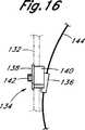
第16図はガイドワイヤが挿通されたクリップアプリケータガイドの側面図である。
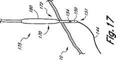
第17図は遠位端部に取外し可能な二重スリーブ付きバルーンを有する拡張器の拡大斜視図である。
第18図はバルーンのスリーブを膨らました状態の第17図の拡張器の拡大斜視図である。
第19図はバルーンのスリーブ間に挿入されたレトラクターの別の具体例を有する第18図の拡張器の拡大斜視図である。
第20図はレトラクターおよびバルーンの外側スリーブにより形成されたトンネルを示し、拡張器を取外した状態の第19図の拡張器およびレトラクターの拡大斜視図である。
好適な実施例の詳細な説明
前置き
下記の説明は大腿部の動脈における刺し傷の閉鎖を詳細に示しているが、本発明は大腿部の動脈にのみ使用することに限定するものではない。むしろ、下記の説明は単に例示的なものであって、当業者は血管系に対する他の種類の創傷に使用するように以下に説明する方法を容易に変更できよう。
まず第1図を参照すると、血管形成法または血管造影法中、大腿部動脈10が代表的に接近されて刺された箇所5を示す人間の身体の一部の側面図が示されている。これらの手順中、中空の針15をまず、皮膚を通して大腿部動脈10に挿入する。次いで、第4図に示すように、ガイドワイヤ20を中空針15の近位端部を通して動脈10に挿入し、針15を患者から抜き取る。ガイドワイヤ20を所望の位置へ差し向ける助けとして、しばしば、X線造影を使用して、ガイドワイヤ20を患者の血管構造を通して前進させる。
ガイドワイヤ20が所望の位置にあると、カテーテルを使用する。ガイドワイヤ21の近位端部をカテーテルの遠位端部に挿入し、カテーテルをガイドワイヤ20上に沿って通し、所望の位置まで前進させる。血管形成法の場合、カテーテルは遠位端部に取付けられた膨らまし可能なバルーンを有している。狭窄部内の適所にあると、バルーンを繰り返し膨らましたり窄ませたりして狭くなった血管を広げる。血管造影法の場合、すぐ上で述べたようにカテーテルをガイドワイヤ20上に沿って検査べき血管の中へ通す。次いで、患部の血管に沿った血液の流れを調べることができるよう、コントラスト媒体を注入し、急速な連続X線写真を取る。
これらの手順のいずれかが完了した後、カテーテルおよびガイドワイヤ20を血管および患者から抜き取る。中空針15、ガイドワイヤ20およびカテーテルの挿入により生じられる大腿部動脈10の刺し傷25を閉じて、動脈10の刺し箇所25を通る出血を留めなければならない。
レトラクターの構成
大腿部動脈10の創傷25を閉じ易くするために、レトラクター30を用いる。レトラクター30は、第2図および第3図に示すように、ボディ部分35およびキャップ40を備えている。レトラクター30のボディ35は幅狭いテーパした遠位端部37および幅広い円形の近位端部41を有している。この装置30は各半体35a、35bに1つずつ、そのボディ35に位置決めされた2つの把手43、45を有している。把手43、45はレトラクター41の近位端部からほぼ3分の1のところに位置決めされており、レトラクター35のボディから横方向に延びている。これらの把手43、45は使用者が装置30を取り扱うのを助ける。また、レトラクター30は穴47を有する円形キャップ40を近位端部41に備えている。この穴47は装置30の全長にわたって延びているチャンネル50の中へ延びている。
図3に示すように、レトラクター30のキャップ40およびボディ35は分離可能な部片、キャップ部分40およびボディ部分の2つの半体35a、35bよりなる。取外し可能はキャップ40は雌ねじ55になっている。ボディの2つの半体35a、35bの近位端部39は雄ねじ60になっており、キャップ40を取外し可能に受け入れるようになっている。レトラクターのボディの各半体35a、35bはその平らな内面67に半円形の溝65を有している。キャップ40を第2図に示すようにボディの両半体35a、35bに確実にねじ込むと、3つの部片は相互に接合され、半円形溝65は装置30の内部を通って延びるチャンネル50を形成し、このチャンネル50は近位端部41におけるキャップ47の穴のところで始まって、ボディ35を通って連続し、ボディの両半体35a、35bが合わさるところのレトラクター37の遠位端部の小さい穴49で終わっている。キャップ40をボディ35から外すと、ボディの両半体35a、35bを第3図に示すように互いに離れる方向に移動させることができる。
レトラクターの別の実施例
本発明の他の好適な実施例が第9図および第10図に示されている。この実施例では、レトラクター100は引っ込み機構を有しており、この引っ込み機構によりレトラクターボディ102の2つの半体102a、102bをそれらの整合を維持しながら所望距離、互いに離れる方向に移動することができる。また、レトラクターはボディ部分102および環状キャップ104を備えている。ボディの両半体102a、102bは雌ねじ105キャップ104により初めに互いにに保持されている。このキャップ104はレトラクターボディの雄ねじ半体102a、102bに対してねじ付けたり外したりされる。キャップの外面106はキャップ104を手で締めつけたり緩めたりするのを容易にするように構成されている。第10図に示すように、レトラクターボディの半体102a、102bはその平らな内面128の中心から長さ方向下方に延びる半円形の溝126を有している。内面128が互いにに当接するようにキャップ104をレトラクターボディの両半体102a、102bにしっかりねじ付けると、半円形の溝126はチャンネル108を形成する。キャップ104はチャンネル108に接近し得るようにその中心を通って両端部が開放している。
更に、レトラクター100は第9図および第10図に示すように、雄ねじ近位端部103から離れてレトラクターボディ102に位置決めされたカラー110と、一端が直角な把手116cに、他端部が箇所124a、124bでレトラクターボディの一方の半体102a取付けられた2つの平行ピン116a、116bよりなるピン組立体116と、2つの押えねじ120a、120bを備えている。第10図に示すように、ピン116a、116bは、レトラクターボディの一方の半体102bがピン116a上を他方の半体102aから離れる方向に摺動することができるようにレトラクターボディの一方の半体102bのカラー領域110bを通って設けられた案内通路118a、118bを横切っている。カラー110bは雄ねじ式押えねじ120a、120bを受け入れるようになっている雌ねじ穴122a、122bを有している。押えねじ120a、120bは、これらを前進させると、ピン116a、160bを締めつけ、かくしてレトラクターボディの両半体102a、102b間の距離を固定するようにピン案内通路118a、118bに対して直角にカラー領域110aに入る。
第11図ないし第13図に示すように、レトラクター100は好ましくは拡張器150と協働して使用される。当業者には公知のように、中空拡張器150は好ましくはその近位端部にルアーコネクタのような標準雄コネクタを有しており、その遠位端部が幅狭くテーパになっている。拡張器150の内径はガイドワイヤを受け入れるのに十分に大きく、従って、拡張器150をガイドワイヤ144に沿って大腿部動脈の内腔に供給することができる。拡張器は一般には、刺し箇所を拡大し、大腿部動脈への接近を向上させるために血管形成法および血管造影法のような手順に使用される。本発明によれば、拡張器は好ましくはその全周にわたってその遠位端部151の近くで切欠き152、153が形成されている。切欠き152は、レトラクター100を拡張器150上に閉じると、レトラクターボディ112の鋭い遠位先端部が拡張器の切欠き152に埋められるようにレトラクターボディの両半体102a、102bのテーパした遠位先端部用の座部をなす。これは拡張器150とレトラクター100との間の滑らかな変化部を形成する(第12図)。切欠き153は、拡張器を適切に位置決めすると、大腿部動脈の壁部が位置する溝をなす。如何により十分に説明するように、ガイドワイヤ144を拡張器150に挿通し、次いで拡張器150をレトラクター100に挿通すると(第12図および第13図)、拡張器150はレトラクターボディ102の長さにわたって延びる円形の内部チャンネル108(第9図)内にしっかり位置する。
また、拡張器150は好ましくは、少なくとも1つの表示穴154を有している。第11図ないし第13図に示す拡張器150は互いに直接対向し、切欠き152から数ミリメートル遠いところに位置決めされた2つの表示穴154(第11図および第12図)を有している。穴154と切欠き153との間の距離Xは好ましくは大腿部動脈の壁部の厚さよりほんのわずかに大きい。変更例として、拡張器150の外側に設けられた先端に変換器の付いた圧力監視カテーテルを拡張器150および表示穴154と協働して使用してもよい。表示穴154および圧力センサの使用を以下に詳細に説明する。
全大腿部動脈局部化/閉鎖組立体を備えた本発明の好適な実施例が第13図に示されている。元の刺し傷から現れるガイドワイヤ144を拡張器150を通して送り、次いで拡張器150をレトラクター100に挿通する。レトラクター100は、その遠位先端部112が拡張器150の切欠き152内に位置するように拡張器150に設けられている。好ましくは、拡張器150の近位端部の雄継手149が市販の3方Yコネクタ156の1つのポートに連結されている。注射器158または負圧を与える他の手段がYコネクタ156の他のポートのうちの1つに連結されており、ガイドワイヤ144の近位端部は残りのポートを経てYコネクタ156の近位端部から出ている。従って、Yコネクタ156は拡張器150およびガイドワイヤ144の近位端部のシールとして作用する。
本発明の別の好適な実施例では、変更された拡張器およびレトラクターを使用する。第17図に示すように、二重スリーブ付きバルーン170が拡張器150に表示穴154より近位のところの遠位端部151の近くに取外し可能に取付けられている。好ましくは、バルーン170はほぼ動脈の壁部の幅、例えば、1.5mmである表示穴154からの距離のところに設置されている。膨らまし可能な二重スリーブ付きバルーン170はこれを大腿部動脈10に嵌まらせるようにその遠位端部のところで傾斜されている。バルーン170はバルーンを膨らましてり窄ましたりする膨らまし手段を有している。レトラクター100は上記のようにテーパした遠位先端部を有するのではなく、円筒形遠位端部を有している。この形状は挿入中、レトラクター100が動脈に入るの防ぐ。二重スリーブ付きバルーン170および円筒形レトラクター100の使用を以下に詳細に説明する。
本発明のレトラクターは好ましくは、多くの強い生物適合性の工学ポリマーのうちの1つで形成されている。ポリプロピレン、ポリエチレンまたはポリテレフタレートのようなプラスチックが好ましい。シラスチックまたはシリコーンのようなエラストマーを使用することもできる。より好ましくは、レトラクターを形成するのに、ステンレス鋼、外科鋼またはチタンのような金属が使用される。
外科クリップアプリケータ
本発明のレトラクターは外科クリップ、ステープルおよび縫い糸を使用して患者の血管構造の創傷を閉じ易くするのに使用される。従って、本発明の一特徴は外科クリップアプリケータ70の使用を含む。本発明のレトラクター30と共に使用する外科クリップアプリケータ70が第5図に示されている。この図に示すように、クリップアプリケータ75の遠位端部には、2つの突出羽根77a、77bが取付けられており、これらの羽根はクリップアプリケータ75の遠位端部の側面から横方向に延びている。これらの羽根77a、77bは第8図で最も良くわかるように、レトラクター30のボディの2つの半体35a、35bの内面に位置決めされた溝65内に嵌合するように構成されている。クリップアプリケータ70の羽根77a、77bがレトラクター30のボディの2つの半体35a、35bの溝65にある状態で、以下により詳細に説明するようにクリップアプリケータ70が患者の身体内の適切な位置へ案内される。また、外科クリップアプリケータ70は好ましくはその遠位端部75に取付けられたガイド80を有している。ガイド80は好ましくはクリップアプリケータ70の側面から横方向に延びており、その近位端部および遠位端部が開放しているので、ガイドワイヤ20をそれに通すことができる。このガイド80は以下に説明するようにクリップアプリケータ70を血管刺し穴25の箇所まで正確に案内するためにガイドワイヤ20との組み合わせで使用される。
また、外科クリップアプリケータ70は好ましくはその羽根77a、77bの羽根の近位端部が終わる箇所で遠位端部75の近くに位置決めされたストッパ85を有している。後述するように、ストッパ85は血管刺し穴25の箇所にクリップアプリケータ70を適切に位置決めするのを助け、且つクリップアプリケータ70が患者の身体に深く挿入されのを防ぐ。
第14図ないし第16図を参照すると、外科クリップアプリケータ130の別の好適な具体例が示されている。このクリップアプリケータ130は標準の市販外科クリップアプリケータ132を組み入れている。本発明によれば、アプリケータはその遠位端部の近くに取外し可能に結ばれたガイド組立体を有するように変更されている。ガイド組立体はボディ140に取外し可能に固着された羽根付きガイドプレート138を備えている。第14図ないし第16図に示す実施例では、ガイドプレート138を取付けるのにアレンねじ142を使用しているが、他の周知な取付け手段を使用することもできる。外科クリップアプリケータの遠位端部は羽根付きガイドプレート138をガイドボディ140に結ぶときに形成されるチャンネル148(第15図)内を摺動する。
ガイドボディ140には、ガイドワイヤ144を受け入れるようになっているガイド管136が取付けられている。上記ガイド管136の好適な実施例は、ガイドワイヤ144が入ると、ガイド管136を閉じる機構を有している。このような機構は上記ガイド管136内に嵌まる第2の部分的に開放した管を含むのがよい。両管の開口を整合させるときに、ガイド管136を開放するか、或いは両管の開口部がずらすときに、ガイド管136を閉鎖するために、この第2管をガイド管136内で回転させることができる。この開放および閉鎖を容易にするために、内側の管は好ましくは外側のガイド管136のスロットを通る把手を有している。この機構は宝石品に一般に使用される閉鎖構造のようにばね付勢することができる。
外科クリップアプリケータガイド組立体134はレトラクター100およびガイドワイヤ144とともに、以下に詳述するように大腿部動脈の刺し穴の箇所でクリップアプリケータ132を正確に案内するように設計されている。上述のように、羽根付きガイドプレート138の横縁部はレトラクターボディの各半体102a、102bの内面に位置決めされた溝126(第10図)に嵌まるように構成されている。外科クリップアプリケータ132はその遠位端部のところでガイド管136を通るガイドワイヤ144に追従してレトラクターボディの引っ込み半体102a、102b間で案内される。
使用方法
まず第4図ないし第8図を参照して、大腿部動脈10に創傷25を閉じるのに外科クリップアプリケータ70と協働してレトラクター30を使用する方法を以下に説明する。上述のように、血管形成法または血管造影法の間、まず大腿部動脈10に中空の針15を刺し、ガイドワイヤ20をそれに挿通する(第4図)。ガイドワイヤ21の近位部分が患者の身体の外側に留まる。ガイドワイヤの遠位端部23が大腿部動脈10内に適所になった後、中空針15を取り出す。次いで、カテーテル(図示せず)をガイドワイヤ20上に沿って通し、患者の身体に挿入する。
好適な実施例では、遠位端部の近くに位置決めされた膨らまし可能なバルーン24を有する特別に設計されたガイドワイヤ20を診断または治療手順に使用する。ガイドワイヤ20を中空針15を通して患者の血管構造に挿入する。変更例として、例えば、バルーン血管形成手順の場合、当業者に周知の標準ガイドワイヤをバルーンカテーテルと協働して使用することができる。ガイドワイヤ20に位置決めされたバルーン24の代わりに、カテーテルの遠位端部のバルーンを使用することができる。
治療手順または診断手順の完了に引続き、手順中に使用したカテーテルを取り出す。ガイドワイヤ20は患者の血管構造に適所に留まる。(なお、遠位端部にバルーンを有するガイドワイヤの代わりにバルーンカテーテルを使用する場合、カテーテルを患者の内側に残し、そのバルーンの使用は後述のガイドワイヤ20のバルーン24の使用と同じである)。
医師が大腿部動脈10の創傷25を閉じたい場合、医師は、まず、ガイドワイヤ20および/またはカテーテルの遠位端部23が大腿部動脈の刺し箇所25に近くで大腿部動脈10内に入るまで、患者の身体21の外側に留まるガイドワイヤ20および/またはカテーテルの一部を使用して患者の血管構造を通してガイドワイヤ20および/またはカテーテルを抜き取る。次いで、ガイドワイヤ20またはカテーテルの遠位端部23のところのバルーン24を膨らまし、医師が幾らかの抵抗を感じるまで、ガイドワイヤ20またはカテーテルを更に抜き取る。これはバルーン24が大腿部動脈10の内側で、刺し傷の箇所にあることを示している。次いで、医師はガイドワイヤ21の近位端部を完全に組み立てられたレトラクター30の遠位端部37に位置決めされた穴49に挿入する(第2図、第3図および第6図)。ガイドワイヤ21の近位端部がレトラクターの近位端部41のところのキャップ40の穴47を通って出るまで(第6図)、ガイドワイヤ20をレトラクター35のボディに形成されたチャンネルに通す。次いで、抵抗が感じられるまで、レトラクター30をガイドワイヤ20に沿って患者の身体の中へゆっくり前進させる。抵抗はレトラクターの遠位端部37が大腿部動脈10内の膨らまされたバルーン24に接触している示している。従って、レトラクターの遠位端部37は第6図に示すように、大腿部動脈25における刺し穴の箇所に適切に位置決めされる。
好適な実施例では、大腿部動脈閉鎖レトラクター30と協働して使用されるガイドワイヤ20はこれを適切に位置決めしたことを示すのを助ける印し27を有している(第6図)。印し27は好ましくはガイドワイヤ20の小さいビードまたは着色線よりなる。ガイドワイヤ上の印し27はバルーンの遠位端部26から近位のところに設置されている。レトラクター30の長さを測定し、印し27はバルーン26の近位端部から測定して、ガイドワイヤ20の近位方向に少なくとも同じ長さで形成される。かくして、レトラクター30をガイドワイヤ20上に沿って前進させ、抵抗を感じると、医師は第6図に示すようにガイドワイヤ上の印し27がレトラクターの近位端部41を通って出たかどうかを見るためにチェックする。印し27がまだ見えない場合、医師はレトラクター30をこれが大腿部動脈の刺し箇所25に接触するように更に前進させなければならない。
レトラクター30が患者の身体内に位置決めされると、外科クリップアプリケータ70または刺し傷25を閉じる他の方法を使用する。まず、レトラクター30のキャップ40をねじを緩めることによりボディから取り外す。レトラクターの近位端部から出たガイドワイヤの近位端部21を第7図に示すようにアプリケータ70の外面に位置決めされたガイド80に通す。レトラクターのボディの半体35a、35bの内面に配置された溝65にアプリケータ30の羽根77a、77bを整合させることによって、これらの羽根77a、77bをレトラクターのボディの近位端部39に形成された穴90に挿入する(第7図および第8図)。クリップアプリケータの羽根77a、77bは第8図の最も良く示すようにレトラクター30の溝65内に嵌まるように寸法決めされている。クリップアプリケータ70を前進させ、これにより第7図に示すようにレトラクターのボディの両半体35a、35bを分離させる。両半体35a、35bが分離すると、患者の組織を横方向に変位させて上側の組織の下方の大腿部動脈10における刺し箇所25に対する良好な接近を可能にする。クリップアプリケータ70のストッパ85がレトラクターの近位端部39に接触するまでクリップアプリケータ70をレトラクター30を通して前進させる。この時、ガイドワイヤまたはカテーテルのバルーン24をしぼませ、カテーテルおよび/またはガイドワイヤ20を患者から取り外す。当業者に周知な方法を使用して、クリップアプリケータの遠位端部に位置決めされた外科クリップを刺し傷25に付ける。大腿部動脈の刺し傷25を閉じると、クリップアプリケータ70およびレトラクター30を患者から取り外す。
第9図ないし第16図を参照して、拡張器150および外科クリップアプリケータ組立体130と協働してレトラクター100の別の実施例を使用して大腿部動脈の刺し傷を局部化して閉じる方法を以下に説明する。上記のように、血管形成法または血管造影法の完了に引続き、手順中に使用したカテーテルを患者の身体から取り外し、大腿部動脈に挿入されたガイドワイヤだけを残す。望むなら、レトラクター/拡張器組立体101(第13図)を使用する前に、レトラクター/拡張器組立体101に組入れられた拡張器150より小さい直径の標準拡張器をガイドワイヤの近位端部へ送り、ガイドワイヤを下って動脈の中へ前進させることができる。この予備工程は必要なら、上側の組織拡張して、より大きいレトラクター/拡張器組立体101を周囲の組織に通すのを容易にする。
組織を以上のように拡張したら、まず、孔径のより小さい標準拡張器を取り外す。初めに、ガイドワイヤの近位端部144を拡張器150の遠位チャンネル160(第11図)に挿入する。拡張器150はレトラクター100の内部チャンネルに予め挿通されており、レトラクター100は遠位先端部112が拡張器150の遠位先端部の切欠き152に静止するように拡張器150に設けられている。次いで、Yコネクタ156を拡張器150の近位端部に取付け、注射器158をコネクタ156のポートのうちの1つに取付ける。次いで、レトラクター/拡張器組立体101をガイドワイヤ上に沿って患者の身体の中へ前進させる。
レトラクター/拡張器組立体101を患者の身体の中へ前進させる間、注射器158または他の負圧源(第13図)を経て拡張器150に吸引を連続的に付与する。表示穴154が大腿部動脈の内腔に入ると、血液が注射器158中へ吸い込まれ、これは拡張器150が刺し箇所を通して大腿部動脈に挿入されたことを示している。かくして、拡張器150の切欠き152にまだ埋まっているレトラクターの遠位先端部112は刺し傷の箇所で動脈壁部のすぐ近くに、すなわち、その外側に位置決めされ、拡張器150の表示穴154は動脈内腔から遠くに、すなわち、その内側に位置決めされる。
変更例として、拡張器150はその遠位先端部にファイバオプチック圧力センサのような圧力センサ(図示せず)を有している。好適な実施例では、カミノラボラトリーズ(サンジエゴ、CA)から市販されているカミノカテーテルのような先端に変換器の付いた圧力監視カテーテルを使用する。圧力センサは、これを大腿部動脈に挿入すると、圧力監視装置と協働して圧力の増大を示す。この時点で、レトラクター100の前進を止めて、レトラクターの遠位先端部112が刺し傷の箇所で動脈壁部の近くに位置決めされる。これにより、医師は患者の大腿部動脈の刺し傷の箇所を適切に見つけることができる。
拡張器150およびレトラクター100が適切な位置になれば、キャップ104をレトラクター100から取出し、押えねじ120a、120bを緩め、レトラクターの2つの半体120a、120bを互いに離れる方向に横方向に摺動させることによってレトラクターボディの2つの半体102a、102bをわずかに分離する(第10図)。これにより2つの半体102a、102bの遠位先端部112が拡張器150の切欠き152から出、刺し箇所に跨がる。次いで、押えねじ120a、120bを締めてレトラクターの2つの半体102a、102bを分離位置に保持する。レトラクター100を押し下げて大腿部動脈の外壁部に当てると、拡張器150を抜取り、レトラクター100およびガイドワイヤ144のみを動脈における刺し傷の箇所で適所に残す。
創傷を閉じるためには、レトラクター100を外科クリップアプリケータ組立体130を刺し箇所に接近させるのに十分遠くに引っ込ませなければならない。押えねじ120a、120bを緩めると、レトラクターのピン把手116c(第9図および第10図)に圧力を加えることによってレトラクターの2つの半体102a、102bを更に分離する。レトラクターを十分に引っ込ませると、レトラクター組立体100の押えねじ120a、120bを締めてレトラクター半体間に適切な距離を維持する。必要なら、レトラクターボディの各半体102a、102bの溝126内の摺動に適した厚さと、外科クリップアプリケータガイド組立体134の羽根付きガイドプレート138(第14図)の幅に等しい幅とを有する別体のレトラクターを使用してレトラクターボディを適切な距離に開放することができる。
第17図に示す別の好適な実施例では、拡張器の遠位端部151に取外し可能に取付けられた二重スリーブ付き膨らまし可能なバルーン170を表示穴154のすぐ近くに有する変更拡張器150を使用する。二重スリーブ付きバルーン170の内側および外側スリーブは、これらを互いに離れる方向に横に移動させると、取外しできる。バルーン拡張器装置175をガイドワイヤ144上に沿って患者の身体に挿入する。上述のように、バルーン拡張器装置175を前進させると、負圧が注射器または他の源を経て装置に加えられる。次いで、二重スリーブ付きバルーン170を膨らまして第18図に示すように大腿部動脈の刺し傷と患者の身体の表面との間にトンネルを形成する。
二重スリーブ付きバルーン170は有利に、大腿部動脈閉鎖レトラクター100が大腿部動脈10に入ってこの動脈を損傷することを防ぐ。また、レトラクター100の遠位端部の円筒形形状はレトラクターが動脈10に入るのを防ぐ。万一、窄んだバルーン170が大腿部動脈10の中へ前進されると、バルーン170を膨らます工程がバルーン170を動脈10から引き出し、それにより動脈10に接近するのに使用されるトンネル176を安全に形成する。
バルーン170は好ましくは第17図ないし第19図に示すようにバルーン170が大腿部動脈10にぴったり合うようにその遠位端部のところで傾斜されている。
バルーン170を膨らますと(第18図)、レトラクター100を膨らまされたバルーン170の2つのスリーブ間に前進させる。レトラクター100を、第19図に示すように、その遠位端部112がバルーン170の2つのスリーブの遠位の取外し可能な接合部に達するように、位置決めする。
レトラクター100がバルーン170の2つのスリーブ間に位置決めされると、レトラクターの2つの半体102a、102bが互いに離れる方向に横に移動させ、それによりバルーン170の2つのスリーブを取り外す。内側スリーブ178および拡張器150を患者から取外し、分離レトラクター100およびバルーン170の外側スリーブ180を患者内に残す。
レトラクター100およびバルーンの外側スリーブ180は第20図に示すように大腿部動脈の刺し傷と患者の身体の表面との間に接近トンネル182を形成する。このトンネル182によれば、大腿部動脈の刺し傷をシールするために創傷閉鎖装置の導入を行うことができる。創傷閉鎖装置はこれを創傷箇所まで案内するように作用するガイドワイヤ144上に沿って挿入することができる。
この時点で、レトラクターが大腿部動脈に接近した状態で、ガイドワイヤ144の近位端部を外科クリップアプリケータ組立体130のガイド管136へ挿入し、ガイドプレートの羽根を開放レトラクターボディ102の溝126内に嵌める(第14図ないし第16図)。このとき、クリップアプリケータ組立体130は、外科クリップアプリケータ組立体130の遠位先端部のところのガイド管136を通っているガイドワイヤ144により案内されてレトラクターボディ102の溝126内を摺動して、刺し傷に向けて前進することができる。外科クリップアプリケータ130の遠位先端部が刺し傷の箇所で大腿部動脈10の外壁部に達すると、外科医はガイドワイヤ144を患者の身体から抜取り、外科クリップをすぐに配置する。次いで、創傷を閉じるために、第2クリップを第1クリップから1または2mm離れて配置することができる。
好適な実施例では、刺し箇所の閉鎖のすぐ前に、主手順中に使用された可撓性ガイドワイヤ144を、フックを形成する遠位端部で剛性になるのがよい市販の可変剛性のガイドワイヤと交換する。フック付きの遠位端部は好ましくは大腿部動脈と腸骨動脈との二股部をフック掛けするのに使用される。二股部でフック掛けされると、ガイドワイヤは患者の血管構造から引き出されることはない。かくして、抵抗が感じられ、ガイドワイヤが二股部でフック掛けされると、ガイドワイヤを更に引き戻し、わずかに上昇させて、刺し傷を線形のスリットの中へ引き入れ、創傷の縁部を互いに合わせて創傷を外科クリップにより閉じ易くする。
また、レトラクターは外科ステープルまたは縫い糸とともに使用することもできる。レトラクターを上記のように患者の身体に挿入し、刺し箇所内に位置決めした後、レトラクターの2つの半体を手で分離し、刺し箇所25を取り囲む組織を横方向に変位させる。レトラクターは拡張器のように作用して、刺し傷が医師により見えるまで、上側の組織の変位を次第に増す。次いで、外科ステープルおよび縫い糸を含めて、創傷閉鎖のための任意の許容可能手段を使用して創傷を閉じることができる。
幾つかの実施例および例を使用して本発明を例示して説明したが、本発明の範囲はここに記載の特定の実施例に限定されるものではない。本発明の範囲は下記請求項により定められるものである。Field of Invention
The present invention relates to a device that assists in closing stabs or other wounds in a patient's vasculature. Specifically, the present invention locates the hole in the vasculature, isolates the hole, guides the appropriate wound closure device to that location, and closes the wound using surgical clips, sutures or staples. The invention relates to a vascular wound closure device to assist.
Background of the Invention
Transluminal balloon angioplasty is used to treat peripheral vascular disease that increases or restores blood flow through significantly narrowed arteries in the limbs. It is also used to treat coronary artery occlusion. Indeed, coronary angioplasty has emerged as the main feasible modification to bypass surgery for stenotic and occluded coronary vascular revascularization. Unlike bypass surgery, angioplasty does not require general anesthesia, chest wall opening, use of a cardiopulmonary machine, or blood transfusion. Angioplasty is not only less invasive and traumatic to the patient, but is also less expensive due to shorter hospital stays and shorter recovery times.
Transluminal balloon angioplasty is performed by first inserting a hollow needle through the skin and into the patient's femoral artery. The guide wire is advanced through the hollow needle into the artery and then advanced along the patient's vasculature toward the location of the occluded blood vessel or heart valve to be treated. X-ray imaging is used to help move the guidewire through the vasculature just past the stenosis to be treated. The balloon catheter is then passed over the guide wire and the balloon catheter is advanced until the deflated balloon enters the stenosis. The balloon is then repeatedly inflated to widen the narrowed blood vessel. After the procedure is complete, the catheter and guidewire are withdrawn from the vessel and the patient.
Angiography used to detect diseases that alter the appearance of blood vessels is performed in a similar manner. First, a hollow needle is inserted through the skin and inserted into the femoral artery, and then a guide wire is inserted through the needle and inserted into the affected blood vessel. The catheter is then passed over the guide wire using X-ray contrast to guide the catheter to the desired location and inserted into the blood vessel to be examined. A contrast medium is then injected and a rapid serial radiograph is taken so that the blood flow along the affected vessel can be examined. When complete, the catheter and guidewire are removed from the patient's body.
After removal of the catheter and guidewire used during angioplasty or angiography, the puncture in the femoral artery must be closed to stop bleeding from the puncture site in the artery. Currently, ice packs and pressure are applied to the artery for a period lasting several hours in an attempt to stop bleeding. Efforts have been made to close the stab using staples, clips and sutures, but these efforts primarily identify the location of the stab in the femoral artery and visualize this stab. I could n’t succeed because I could n’t.
Also, other wounds are difficult to locate and access the patient's vasculature. Thus, devices and methods that facilitate endoluminal balloon angioplasty and angiography and thus facilitate closure of wounds in a patient's vasculature, such as a femoral artery stab, are extremely advantageous. Devices that have the ability to find the location of the stab and assist in making the wound easier to close using staples, clips or sutures currently eliminate the long-term bleeding associated with such wounds.
Summary of the Invention
The wound closure device of the present invention assists in locating and isolating puncture locations in a patient's vasculature. This device is used in conjunction with a guidewire normally inserted into the vasculature during diagnostic and therapeutic procedures. The device of the present invention helps the physician close the wound, thus eliminating the long-term bleeding associated with these procedures.
According to one aspect of the present invention, an apparatus is provided for facilitating closure of a wound in a femoral artery. The device includes a body portion having a male thread proximal end and a tapered distal end. The body part is separable into two halves, each half having a flat inner surface with a groove, when the inner surface abuts each other, the groove forms a channel through the body part. It is like that. The retractor also has a female screw cap with a hole. The female threaded portion is adapted to engage the male threaded portion of the body portion, and when the cap is engaged with the body portion, the hole is positioned just above the channel of the body portion and extends by the length of the retractor. Form a continuous channel.
In one embodiment of the invention, the apparatus further comprises at least one handle positioned at the proximal end of the body portion and extending laterally from the body portion. The body portion and cap are preferably made of a biocompatible engineering polymer such as polypropylene, polyethylene, or polytetraphthalate. The body part and the cap can also be made of an elastomer. More preferably, the body portion and the cap are made of a metal such as stainless steel.
In another embodiment of the invention, the device further comprises a guide wire. The guide wire is inserted through the channel of the body part and the hole of the cap. Preferably, the guidewire has an inflatable balloon attached near its distal end.
According to another aspect of the invention, an apparatus is provided for facilitating closure of a wound in a patient's vasculature. The device includes a retractor having a body portion with a male thread proximal end and a tapered distal end. The body part is separable into two halves, each half having a flat inner surface with a groove so that when the inner surfaces abut each other, the groove forms a channel through the body part. Yes. The retractor also has a female screw cap through which a hole passes. The female threaded portion is adapted to engage the male threaded portion of the body portion, and when the cap engages the body portion, the hole is positioned just above the body channel.
In addition, the device includes a guide wire with an inflatable balloon attached thereto. The guide wire is inserted through the channel of the body part and the hole of the cap. A surgical clip applicator having a distal end and provided with two laterally projecting wings is also used. The vanes are adapted to fit within a channel in the body part of the retractor. Further, the surgical clip applicator includes a guide attached to its distal end and extending laterally therefrom. The guide is adapted to receive a guide wire through its end.
According to yet another aspect of the invention, a method is provided for facilitating closure of a wound in a patient's vasculature. This method removes a guidewire having a proximal end and a distal end and an inflatable balloon until the distal end of the guidewire enters the vasculature and remains outside the patient's body. The proximal end of the guide wire is withdrawn from the patient's body until the inflated balloon is positioned within the vasculature at the wound location and the proximal end of the guide wire is removed at the distal end of the retractor It is equipped with various processes to be inserted into the part. Insert the proximal end of the guidewire into the retractor until it exits through the hole in the cap. In addition, the method advances the retractor along the guide wire until its distal end contacts the inflated balloon and enters the patient's body, removes the cap from the body portion of the retractor until the wound is visible. Separating the two halves of the retractor and closing the wound. The closing step preferably consists of either clipping, stapling or sewing the wound.
In a preferred method, the surgical clip applicator is inserted into the retractor after removing the cap. The clip applicator is advanced through the channel in the body part until it contacts the wound. The closing step preferably comprises applying at least one surgical clip to the wound.
The method preferably further constricts the balloon and removes the guide wire from the patient's body prior to the closing step.
According to yet another aspect of the present invention, another method for facilitating closure of a wound in a patient's vasculature is provided. This method inserts a guidewire having a proximal end and a distal end into the vasculature until the distal end enters the vasculature and remains outside the patient's body, A catheter having a distal end with an inflatable balloon attached to the vasculature along the guide wire until the distal end enters the artery and the proximal end remains outside the patient's body. Insert and inflate the inflatable balloon, withdraw the catheter from the patient's body until the inflated balloon is positioned within the vasculature at the site of the wound, and insert the guidewire and catheter into the distal end of the retractor It has various processes to do. The guidewire and catheter are advanced as a unit until the proximal end of the guidewire exits through the hole in the retractor cap.
Further, the method advances the retractor along the guidewire and catheter and inserts it into the patient's body until the distal end of the retractor contacts the inflated balloon, and the cap is inserted into the body part of the retractor. The two halves of the retractor are separated until the wound is visible, leaving the guide wire to guide the wound closure device to the wound site, withdrawing the catheter from the patient, removing the guide wire and removing the wound It has various closing processes. The closing step preferably consists of either clipping, stapling and sewing the wound.
In a preferred embodiment, the method further includes inserting the surgical clip applicator into the body portion of the retractor after removing the cap, and through the channel of the body portion along the guide wire until the clip applicator contacts the wound. Steps for advancing the clip applicator are provided. The closing step preferably comprises applying at least one surgical clip to the wound.
In yet another preferred embodiment, the method of the present invention further comprises the steps of constricting the balloon and extracting the catheter and guide wire from the patient's body prior to the closing step.
In yet another preferred embodiment of the present invention, an apparatus for facilitating closure of a wound in a patient's vasculature is disclosed. The device includes a body portion having a male thread proximal end and a tapered distal end. The body part is separable into two halves, each having a flat inner surface with a groove so that when the inner surfaces abut each other, the groove forms a channel through the body part. . The device also has a collar portion remote from the proximal end of the male thread, the collar portion having at least one guide passage across both halves of the body portion. The device also includes at least one pin insertable into the guide passage and a female threaded tubular cap. The female screw portion is adapted to engage with the male screw portion of the body portion. The apparatus also includes a handle extending laterally from the pin, at least one cap screw hole formed in the collar portion at right angles to the guide passage, and at least one cap screw.
The device also preferably comprises a hollow dilator having an open proximal end and an open distal end adapted to receive a guide wire. The dilator can be inserted through the body part channel and the tubular cap. In addition, the dilator includes a notch sized near the distal end that is sized to receive the tapered distal end of the device. The dilator preferably has at least one indicator hole through the side wall positioned away from the notch. In addition, a pressure sensor can be attached to the outer wall of the dilator.
In the preferred embodiment, a guide wire is inserted through the hollow dilator. The hollow dilator has an open proximal end and an open distal end adapted to receive a guide wire, and the dilator can be inserted through the channel and tubular cap of the body portion. The dilator may also have a double sleeve inflatable balloon provided at its distal end and at least one indicator hole. An inflatable balloon with a double sleeve is provided in the vicinity of about 1.5 mm from the display hole.
The device preferably comprises a biocompatible polymer such as polypropylene, polyethylene or polyterephthalate or elastomer, or a metal such as stainless steel.
According to yet another aspect of the invention, an apparatus is provided for facilitating closure of a wound in a patient's vasculature. The device includes a retractor, a hollow dilator adapted to receive a guide wire, and a guide wire. A guide assembly adapted to attach to the distal end of the surgical clip applicator can also be used. The assembly includes a guide plate that is removably attachable to a guide body having a mounting tube dimensioned to receive a guide wire. The guide plate has two laterally projecting vanes attached to fit into the channel of the retractor.
The device also preferably includes a negative pressure source attached to the proximal end of a dilator, such as a syringe. A Y connector having multiple ports may be attached to the proximal end of the dilator and a negative pressure source may be attached to one of the ports of the Y connector.
According to yet another aspect of the invention, a method is provided for facilitating closure of a wound in a patient's vasculature. The method includes a proximal end of a hollow dilator having a notch near the distal end and a distal end of a retractor with a body portion having a round male screw proximal end and a tapered distal end. Attach the retractor to the dilator so that the tapered distal end is positioned within the dilation notch, insert the guidewire through the wound and into the patient's blood vessel, and insert the proximal end of the guidewire Insert the proximal end of the guidewire into the distal end of the dilator with the retractor attached until the part exits through the proximal end of the dilator and negative until blood is drawn into the dilator from the blood vessel. Advance the dilator and retractor along the guidewire into the patient's body with the pressure source in the expansion, remove the cap from the retractor, separate the two halves of the retractor, the guidewire and the expansion Instrument on patient's body Luo taken out to close the wound and includes various steps.
The wound can be closed by clipping, stapling or sewing. Preferably, the method further includes attaching a guide having a laterally extending wing to the distal end of the surgical clip applicator, inserting the wing into the body portion of the retractor, and inserting the clip applicator until it contacts the wound. It has various steps to advance through the channel of the tractor. At least one surgical clip is then applied to the wound.
The guide preferably has a guide tube for receiving the guide wire, and the method further comprises inserting the proximal end of the guide wire through the guide tube. The applicator is advanced through the retractor channel along the guide wire until it contacts the wound.
According to yet another aspect of the present invention, a method for facilitating closure of a wound in a patient's vasculature, wherein the guidewire has a distal end within the vasculature and a proximal end external to the patient's body Insert into the vasculature through the wound until it remains in place, insert the proximal end of the guidewire into a hollow dilator with a double-sleeved balloon at the distal end, and the dilator along the guidewire Advance into the vasculature (this is indicated by the blood being drawn through the dilation, indicating that it has reached the wound), insert the guide wire and dilator into the retractor, and the distal end Advance the retractor between the two sleeves of the double sleeved balloon until the part reaches the distal removable joint of the two sleeves, remove the cap from the retractor, Remove the inner half of the balloon with dilator and double sleeve, leaving the guide wire in place to separate the halves and guide the wound closure device to the wound (where the outer sleeve of the balloon is the body surface A tunnel from the wound to the wound), a method is provided comprising the steps of removing the guide wire and closing the wound. Wound closure can be accomplished by clipping, stapling and sewing.
Preferably, the method attaches a guide having a laterally extending wing to the distal end of the surgical clip applicator and inserts the wing into the retractor after removing the cap until the clip applicator contacts the wound. It has various steps to advance through the retractor channel. At least one surgical clip is then applied to the wound.
The guide preferably further comprises a guide tube for receiving the guide wire, and the method further includes inserting the guide wire through the guide tube and passing the applicator along the guide wire until it contacts the wound. Includes moving forward through the channel.
The claimed method also preferably includes providing a dilator with a negative pressure source during the advancement of the dilator along the guidewire until blood is drawn from the vasculature into the dilator.
[Brief description of the drawings]
FIG. 1 is a side view of a portion of a human body that typically shows where a thigh artery is approached and stabbed during angioplasty and angiography.
FIG. 2 is a perspective view of one embodiment of the wound closure device of the present invention.
FIG. 3 is an exploded perspective view of the wound closure device of the present invention.
FIG. 4 is an illustration of a human body showing a femoral artery approached through a hollow needle and a guide wire attached to an inflatable balloon and inserted into the femoral artery through the hollow needle. FIG.
FIG. 5 is a side view of the distal end of a surgical clip applicator used in conjunction with the wound closure device of the present invention.
FIG. 6 shows a partial cross-sectional view of a portion of the human body showing the femoral artery with the guidewire positioned, and the guide with the distal tip at the puncture site of the femoral artery FIG. 3 is a perspective view of a retractor of the present invention positioned on a wire.
FIG. 7 is a side view of the retractor with the cap removed and the surgical clip applicator inserted into a groove in the retractor.
FIG. 8 is the clip applicator and retractor crossing cotton along line 8-8 in FIG.
FIG. 9 is a perspective view of another embodiment of a femoral artery closure device according to the present invention.
FIG. 10 is an exploded perspective view of the femoral artery closure device shown in FIG.
FIG. 11 is a side view of the two halves of the retractor of FIGS. 9 and 10 slightly separated and with the expansion inserted.
FIG. 12 is a cross-sectional view of the distal end of the retractor through which the dilator and guide wire are inserted.
FIG. 13 is a side view of the components of the femoral artery localization / closure assembly.
FIG. 14 is a side view of two halves of a retractor with a surgical clip applicator slightly separated and having an applicator guide and guidewire inserted therethrough.
FIG. 15 is a top view of the surgical clip applicator guide of the present invention.
FIG. 16 is a side view of a clip applicator guide through which a guide wire is inserted.
FIG. 17 is an enlarged perspective view of a dilator having a double-sleeved balloon at the distal end.
FIG. 18 is an enlarged perspective view of the dilator of FIG. 17 with the balloon sleeve inflated.
FIG. 19 is an enlarged perspective view of the dilator of FIG. 18 having another embodiment of a retractor inserted between balloon sleeves.
FIG. 20 is an enlarged perspective view of the dilator and retractor of FIG. 19 with the dilator removed, showing the tunnel formed by the retractor and the outer sleeve of the balloon.
Detailed Description of the Preferred Embodiment
Prelude
Although the following description details the closure of a stab wound in a femoral artery, the present invention is not limited to use only in a femoral artery. Rather, the following description is merely exemplary and one of ordinary skill in the art could readily modify the method described below for use with other types of wounds to the vasculature.
Referring first to FIG. 1, there is shown a side view of a portion of a human body showing a
When the
After either of these procedures is complete, the catheter and guidewire 20 are withdrawn from the blood vessel and patient. The
Retractor configuration
In order to facilitate closing of the
As shown in FIG. 3, the
Another example of a retractor
Another preferred embodiment of the present invention is shown in FIGS. In this embodiment, the
Further, as shown in FIGS. 9 and 10, the
As shown in FIGS. 11-13, the
The
A preferred embodiment of the present invention with a total femoral artery localization / closure assembly is shown in FIG.
In another preferred embodiment of the present invention, a modified dilator and retractor are used. As shown in FIG. 17, a double-
The retractor of the present invention is preferably formed of one of many strong biocompatible engineering polymers. Plastics such as polypropylene, polyethylene or polyterephthalate are preferred. Elastomers such as silastic or silicone can also be used. More preferably, a metal such as stainless steel, surgical steel or titanium is used to form the retractor.
Surgical clip applicator
The retractor of the present invention is used to facilitate closure of a patient's vasculature wound using surgical clips, staples and sutures. Accordingly, one aspect of the present invention includes the use of a
Referring to FIGS. 14-16, another preferred embodiment of the
A
Surgical clip
how to use
Referring first to FIGS. 4-8, a method for using the
In a preferred embodiment, a specially designed
Following completion of the treatment or diagnostic procedure, the catheter used during the procedure is removed.
If the physician wishes to close the
In the preferred embodiment, the
Once the
9-16, in conjunction with the
When the tissue is expanded as described above, first, the standard dilator having a smaller pore diameter is removed. Initially, the
While the retractor /
Alternatively, the
When the
In order to close the wound,
In another preferred embodiment shown in FIG. 17, a modified
The double
The
When the
When the
At this point, with the retractor approaching the femoral artery, the proximal end of the
In a preferred embodiment, immediately before closure of the puncture site, the
The retractor can also be used with surgical staples or sutures. After the retractor is inserted into the patient's body and positioned within the puncture site as described above, the two halves of the retractor are separated by hand and the tissue surrounding the
Although the present invention has been illustrated and described using several examples and examples, the scope of the present invention is not limited to the specific examples described herein. The scope of the present invention is defined by the following claims.
Claims (40)
Translated fromJapanese近位端と遠位端とを有する細長ボディ部分を備えたレトラクターをさらに含み、前記細長ボディ部分は、選択的に前記中空拡張器上で閉じ、および前記中空拡張器から分離されるようになった分離可能な細長レトラクター部分を備え、該分離可能な細長レトラクター部分は、該分離可能な細長レトラクター部分が前記中空拡張器から分離されるときに身体組織を前記中空拡張器から離れる方へ引っ込めるようになっており、
前記レトラクターの遠位端は、前記拡張器の前記表示穴の近位側に近接して配置される、
ことを特徴とする、患者の血管構造における創傷を見つけ、この創傷に接近するための装置。A hollow dilator having a proximal end and a distal end, the hollow dilator having at least one indicator hole formed through a side wall of the hollow dilator, wherein the indicator hole comprises the hollow Injecting blood into the dilator to indicate that the hollow dilator has been inserted into the patient's vasculature;
And further including a retractor having an elongated body portion having a proximal end and a distal end, wherein the elongated body portion is selectively closed on and separated from the hollow dilator. A separable elongate retractor portion that separates body tissue from the hollow dilator when the separable elongate retractor portion is separated from the hollow dilator. It is now possible to withdraw
A distal end of the retractor is disposed proximate to a proximal side of the indicator hole of the dilator,
A device for finding and accessing a wound in a patient's vasculature characterized in that.
開放した近位端と、開放した遠位端であって、該遠位端を通してガイドワイヤを受け入れるようになった、開放した遠位端とを有する中空拡張器と、を含み、該中空拡張器は、前記ボディ内で前記チャンネルを通して挿入されるように構成され、かつ該中空拡張器の側壁を通して形成された少なくとも1つの表示穴を有し、該少なくとも1つの表示穴は、前記中空拡張器内に血液を流入させて、前記中空拡張器が患者の血管構造内に挿入されたことを表示するようになっている、
ことを特徴とする患者の血管構造における創傷の閉鎖し易くするために患者の血管構造における創傷を見つけ、この創傷に接近するための装置。A retractor having a separable body in two elongate body parts, wherein the two elongate body parts penetrate the body along the length of the body when the two elongate body parts abut each other A retractor configured such that a channel extending between the two elongated body portions is formed;
A proximal end open, an open distal end,wherein adapted to receive a guide wire through the distal end,a hollow dilator that chromatic and an open distalend, ahollow extension A device is configured to be inserted through the channel in the body and has at least one indicator hole formed througha side wall of the hollow dilator, the at least one indicator hole being the hollow dilator Blood is allowed to flow in to indicate that the hollow dilator has been inserted into the patient's vasculature,
A device for finding and accessing a wound in a patient's vasculature to facilitate closure of the wound in the patient's vasculature.
近位端と、遠位端とを有するボディ部分を有するレトラクター、とを有し、前記ボディ部分は、2つの分離可能な半体を有し、該半体の各々は、溝が形成された内面を有し、半体の各々の内面が互いに当接するとき、前記溝が、前記ボディの近位端から前記ボディ部分の遠位端まで前記ボディ部分を完全に貫通するチャンネルを形成し、
貫通して形成された穴を有するキャップをさらに有し、前記キャップは、該キャップの穴が前記チャンネルと連通するように前記レトラクターのボディの近位端に選択的に係合するように構成されており、
前記チャンネルおよび前記キャップの穴は、これらのチャンネルおよびキャップの穴を通して挿入された前記中空拡張器を受け入れるように構成されている、
ことを特徴とする患者の血管構造における創傷の閉鎖し易くするために患者の血管構造における創傷を見つけ、この創傷に接近するための装置。A hollow dilator having an open proximal end and an open distal end adapted to receive a guidewire therethrough;
A retractor having a body portion having a proximal end and a distal end, the body portion having two separable halves, each of the halves being grooved. The grooves form a channel that completely penetrates the body portion from the proximal end of the body to the distal end of the body portion when each inner surface of the halves abut one another.
A cap having a hole formed therethrough, the cap configured to selectively engage a proximal end of the body of the retractor such that the hole in the cap communicates with the channel; Has been
The channels and cap holes are configured to receive the hollow dilators inserted through the channels and cap holes;
A device for finding and accessing a wound in a patient's vasculature to facilitate closure of the wound in the patient's vasculature.
Applications Claiming Priority (5)
| Application Number | Priority Date | Filing Date | Title |
|---|---|---|---|
| US964395P | 1995-12-07 | 1995-12-07 | |
| US60/009,643 | 1995-12-07 | ||
| US08/764,611US6004341A (en) | 1996-12-05 | 1996-12-05 | Vascular wound closure device |
| PCT/US1996/019937WO1997020505A1 (en) | 1995-12-07 | 1996-12-05 | Vascular wound closure device |
| US08/764,611 | 1996-12-05 |
Publications (3)
| Publication Number | Publication Date |
|---|---|
| JP2001527431A JP2001527431A (en) | 2001-12-25 |
| JP2001527431A5 JP2001527431A5 (en) | 2004-11-04 |
| JP4185165B2true JP4185165B2 (en) | 2008-11-26 |
Family
ID=26679722
Family Applications (1)
| Application Number | Title | Priority Date | Filing Date |
|---|---|---|---|
| JP52151197AExpired - LifetimeJP4185165B2 (en) | 1995-12-07 | 1996-12-05 | Vascular wound closure device |
Country Status (4)
| Country | Link |
|---|---|
| EP (1) | EP0874591B1 (en) |
| JP (1) | JP4185165B2 (en) |
| DE (1) | DE69638352D1 (en) |
| WO (1) | WO1997020505A1 (en) |
Families Citing this family (97)
| Publication number | Priority date | Publication date | Assignee | Title |
|---|---|---|---|---|
| US20020095164A1 (en) | 1997-06-26 | 2002-07-18 | Andreas Bernard H. | Device and method for suturing tissue |
| US6562052B2 (en) | 1995-08-24 | 2003-05-13 | Sutura, Inc. | Suturing device and method |
| US6117144A (en)* | 1995-08-24 | 2000-09-12 | Sutura, Inc. | Suturing device and method for sealing an opening in a blood vessel or other biological structure |
| US6287322B1 (en) | 1995-12-07 | 2001-09-11 | Loma Linda University Medical Center | Tissue opening locator and everter and method |
| US6524326B1 (en) | 1995-12-07 | 2003-02-25 | Loma Linda University Medical Center | Tissue opening locator and everter and method |
| US6425901B1 (en)* | 1995-12-07 | 2002-07-30 | Loma Linda University Medical Center | Vascular wound closure system |
| US6004341A (en)* | 1996-12-05 | 1999-12-21 | Loma Linda University Medical Center | Vascular wound closure device |
| GB2318295A (en) | 1996-10-17 | 1998-04-22 | Malachy Gleeson | Wire-guided surgical stapler for closure of a puncture site in a blood vessel |
| US8137364B2 (en) | 2003-09-11 | 2012-03-20 | Abbott Laboratories | Articulating suturing device and method |
| US7842048B2 (en) | 2006-08-18 | 2010-11-30 | Abbott Laboratories | Articulating suture device and method |
| US7001400B1 (en) | 1999-03-04 | 2006-02-21 | Abbott Laboratories | Articulating suturing device and method |
| US7235087B2 (en) | 1999-03-04 | 2007-06-26 | Abbott Park | Articulating suturing device and method |
| US6964668B2 (en) | 1999-03-04 | 2005-11-15 | Abbott Laboratories | Articulating suturing device and method |
| ATE329531T1 (en) | 1999-07-02 | 2006-07-15 | Quickpass Inc | SURGICAL SEWING DEVICE |
| US6358258B1 (en) | 1999-09-14 | 2002-03-19 | Abbott Laboratories | Device and method for performing end-to-side anastomosis |
| US8758400B2 (en) | 2000-01-05 | 2014-06-24 | Integrated Vascular Systems, Inc. | Closure system and methods of use |
| US6461364B1 (en) | 2000-01-05 | 2002-10-08 | Integrated Vascular Systems, Inc. | Vascular sheath with bioabsorbable puncture site closure apparatus and methods of use |
| US9579091B2 (en) | 2000-01-05 | 2017-02-28 | Integrated Vascular Systems, Inc. | Closure system and methods of use |
| US6391048B1 (en) | 2000-01-05 | 2002-05-21 | Integrated Vascular Systems, Inc. | Integrated vascular device with puncture site closure component and sealant and methods of use |
| US6197042B1 (en) | 2000-01-05 | 2001-03-06 | Medical Technology Group, Inc. | Vascular sheath with puncture site closure apparatus and methods of use |
| EP1259168B1 (en) | 2000-02-24 | 2010-09-08 | Loma Linda University Medical Center | Patch and glue delivery system for closing tissue openings during surgery |
| WO2001067985A1 (en) | 2000-03-10 | 2001-09-20 | Paracor Surgical, Inc. | Expandable cardiac harness for treating congestive heart failure |
| US6890342B2 (en) | 2000-08-02 | 2005-05-10 | Loma Linda University | Method and apparatus for closing vascular puncture using hemostatic material |
| ZA200006432B (en) | 2000-09-08 | 2000-12-08 | Christy Cummins | Surgical micro-stapling instrument. |
| DE60144328D1 (en) | 2000-09-08 | 2011-05-12 | Abbott Vascular Inc | Surgical clamp |
| US6626918B1 (en) | 2000-10-06 | 2003-09-30 | Medical Technology Group | Apparatus and methods for positioning a vascular sheath |
| US7029481B1 (en) | 2000-11-06 | 2006-04-18 | Abbott Laboratories | Systems, devices and methods for suturing patient tissue |
| US8690910B2 (en) | 2000-12-07 | 2014-04-08 | Integrated Vascular Systems, Inc. | Closure device and methods for making and using them |
| US6623510B2 (en) | 2000-12-07 | 2003-09-23 | Integrated Vascular Systems, Inc. | Closure device and methods for making and using them |
| US6695867B2 (en) | 2002-02-21 | 2004-02-24 | Integrated Vascular Systems, Inc. | Plunger apparatus and methods for delivering a closure device |
| US7905900B2 (en) | 2003-01-30 | 2011-03-15 | Integrated Vascular Systems, Inc. | Clip applier and methods of use |
| IES20010547A2 (en) | 2001-06-07 | 2002-12-11 | Christy Cummins | Surgical Staple |
| IES20010748A2 (en) | 2001-08-09 | 2003-02-19 | Christy Cummins | Surgical Stapling Device and Method |
| IES20010749A2 (en) | 2001-08-09 | 2003-02-19 | Christy Cummins | Surgical Stapling Device |
| EP1424958A2 (en) | 2001-09-10 | 2004-06-09 | Paracor Medical, Inc. | Cardiac harness |
| WO2003037217A1 (en) | 2001-10-31 | 2003-05-08 | Paracor Medical, Inc. | Heart failure treatment device |
| IES20030424A2 (en) | 2002-06-04 | 2003-12-10 | Robert Stevenson | Blood vessel closure clip and delivery device |
| ATE342000T1 (en)* | 2002-06-14 | 2006-11-15 | Univ Loma Linda Med | DEVICE FOR CLOSING VASCULAR WOUNDS |
| EP1646320B1 (en) | 2002-07-03 | 2009-02-25 | Abbott Vascular Inc | Surgical stapling device |
| EP1534173A2 (en) | 2002-09-05 | 2005-06-01 | Paracor Medical, Inc. | Cardiac harness |
| JP2006506183A (en) | 2002-11-15 | 2006-02-23 | パラコー メディカル インコーポレイテッド | Cardiac harness feeder |
| US7229405B2 (en) | 2002-11-15 | 2007-06-12 | Paracor Medical, Inc. | Cardiac harness delivery device and method of use |
| US7160309B2 (en) | 2002-12-31 | 2007-01-09 | Laveille Kao Voss | Systems for anchoring a medical device in a body lumen |
| US8202293B2 (en) | 2003-01-30 | 2012-06-19 | Integrated Vascular Systems, Inc. | Clip applier and methods of use |
| US8905937B2 (en) | 2009-02-26 | 2014-12-09 | Integrated Vascular Systems, Inc. | Methods and apparatus for locating a surface of a body lumen |
| US8398656B2 (en) | 2003-01-30 | 2013-03-19 | Integrated Vascular Systems, Inc. | Clip applier and methods of use |
| WO2005007032A2 (en) | 2003-07-10 | 2005-01-27 | Paracor Medical, Inc. | Self-anchoring cardiac harness |
| DE602004031953D1 (en) | 2003-08-14 | 2011-05-05 | Univ Loma Linda Med | |
| US8187627B2 (en) | 2003-09-05 | 2012-05-29 | Loma Linda University Medical Center | Dressing delivery system for internal wounds |
| US7462188B2 (en) | 2003-09-26 | 2008-12-09 | Abbott Laboratories | Device and method for suturing intracardiac defects |
| US7155295B2 (en) | 2003-11-07 | 2006-12-26 | Paracor Medical, Inc. | Cardiac harness for treating congestive heart failure and for defibrillating and/or pacing/sensing |
| US7158839B2 (en) | 2003-11-07 | 2007-01-02 | Paracor Medical, Inc. | Cardiac harness for treating heart disease |
| US7390328B2 (en) | 2003-12-19 | 2008-06-24 | Abbott Laboratories | Device and method for suturing of internal puncture sites |
| US7449024B2 (en) | 2003-12-23 | 2008-11-11 | Abbott Laboratories | Suturing device with split arm and method of suturing tissue |
| EP1703854A1 (en) | 2004-01-12 | 2006-09-27 | Paracor Medical, Inc. | Cardiac harness having interconnected strands |
| US8882786B2 (en) | 2004-02-17 | 2014-11-11 | Lawrence Livermore National Security, Llc. | System for closure of a physical anomaly |
| EP1909655A2 (en) | 2005-06-20 | 2008-04-16 | Sutura, Inc. | Method and apparatus for applying a knot to a suture |
| US8926633B2 (en) | 2005-06-24 | 2015-01-06 | Abbott Laboratories | Apparatus and method for delivering a closure element |
| US8313497B2 (en) | 2005-07-01 | 2012-11-20 | Abbott Laboratories | Clip applier and methods of use |
| US7587247B2 (en) | 2005-08-01 | 2009-09-08 | Paracor Medical, Inc. | Cardiac harness having an optimal impedance range |
| US8267947B2 (en) | 2005-08-08 | 2012-09-18 | Abbott Laboratories | Vascular suturing device |
| US9456811B2 (en) | 2005-08-24 | 2016-10-04 | Abbott Vascular Inc. | Vascular closure methods and apparatuses |
| US8920442B2 (en) | 2005-08-24 | 2014-12-30 | Abbott Vascular Inc. | Vascular opening edge eversion methods and apparatuses |
| JP5253170B2 (en) | 2005-10-05 | 2013-07-31 | ローマ リンダ ユニヴァーシティ メディカル センター | Vascular wound closure device and method |
| US8556930B2 (en) | 2006-06-28 | 2013-10-15 | Abbott Laboratories | Vessel closure device |
| US8246636B2 (en) | 2007-03-29 | 2012-08-21 | Nobles Medical Technologies, Inc. | Suturing devices and methods for closing a patent foramen ovale |
| US8893947B2 (en) | 2007-12-17 | 2014-11-25 | Abbott Laboratories | Clip applier and methods of use |
| US8771296B2 (en) | 2008-05-09 | 2014-07-08 | Nobles Medical Technologies Inc. | Suturing devices and methods for suturing an anatomic valve |
| US9282965B2 (en) | 2008-05-16 | 2016-03-15 | Abbott Laboratories | Apparatus and methods for engaging tissue |
| US8398676B2 (en) | 2008-10-30 | 2013-03-19 | Abbott Vascular Inc. | Closure device |
| US8858594B2 (en) | 2008-12-22 | 2014-10-14 | Abbott Laboratories | Curved closure device |
| US9414820B2 (en) | 2009-01-09 | 2016-08-16 | Abbott Vascular Inc. | Closure devices, systems, and methods |
| US20100179589A1 (en) | 2009-01-09 | 2010-07-15 | Abbott Vascular Inc. | Rapidly eroding anchor |
| US9089311B2 (en) | 2009-01-09 | 2015-07-28 | Abbott Vascular Inc. | Vessel closure devices and methods |
| US9173644B2 (en) | 2009-01-09 | 2015-11-03 | Abbott Vascular Inc. | Closure devices, systems, and methods |
| US9486191B2 (en) | 2009-01-09 | 2016-11-08 | Abbott Vascular, Inc. | Closure devices |
| US20100185234A1 (en) | 2009-01-16 | 2010-07-22 | Abbott Vascular Inc. | Closure devices, systems, and methods |
| US20110054492A1 (en) | 2009-08-26 | 2011-03-03 | Abbott Laboratories | Medical device for repairing a fistula |
| US9370353B2 (en) | 2010-09-01 | 2016-06-21 | Abbott Cardiovascular Systems, Inc. | Suturing devices and methods |
| EP3113692B1 (en)* | 2011-01-11 | 2025-09-10 | Amsel Medical Corporation | Apparatus for occluding a blood vessel and/or other tubular structures |
| US9149276B2 (en) | 2011-03-21 | 2015-10-06 | Abbott Cardiovascular Systems, Inc. | Clip and deployment apparatus for tissue closure |
| EP3644194B1 (en) | 2011-04-15 | 2022-12-07 | Heartstitch, Inc. | Suturing devices for suturing an anatomic valve |
| US9332976B2 (en) | 2011-11-30 | 2016-05-10 | Abbott Cardiovascular Systems, Inc. | Tissue closure device |
| US8858573B2 (en) | 2012-04-10 | 2014-10-14 | Abbott Cardiovascular Systems, Inc. | Apparatus and method for suturing body lumens |
| US8864778B2 (en) | 2012-04-10 | 2014-10-21 | Abbott Cardiovascular Systems, Inc. | Apparatus and method for suturing body lumens |
| US9706988B2 (en) | 2012-05-11 | 2017-07-18 | Heartstitch, Inc. | Suturing devices and methods for suturing an anatomic structure |
| US9241707B2 (en) | 2012-05-31 | 2016-01-26 | Abbott Cardiovascular Systems, Inc. | Systems, methods, and devices for closing holes in body lumens |
| US9364209B2 (en) | 2012-12-21 | 2016-06-14 | Abbott Cardiovascular Systems, Inc. | Articulating suturing device |
| WO2015002815A1 (en) | 2013-07-02 | 2015-01-08 | Med-Venture Investments, Llc | Suturing devices and methods for suturing an anatomic structure |
| JP6469109B2 (en) | 2013-12-06 | 2019-02-13 | メッド − ベンチャー インベストメンツ、エルエルシー | Suture method and apparatus |
| US10178993B2 (en) | 2014-07-11 | 2019-01-15 | Cardio Medical Solutions, Inc. | Device and method for assisting end-to-side anastomosis |
| WO2017180092A1 (en) | 2016-04-11 | 2017-10-19 | Nobles Medical Technologies Ii, Inc. | Suture spools for tissue suturing device |
| US10426449B2 (en) | 2017-02-16 | 2019-10-01 | Abbott Cardiovascular Systems, Inc. | Articulating suturing device with improved actuation and alignment mechanisms |
| EP3641660B1 (en) | 2017-06-19 | 2024-11-20 | Heartstitch, Inc. | Suturing devices for suturing an opening in the apex of the heart |
| EP4115818A3 (en) | 2017-06-19 | 2023-04-05 | Heartstitch, Inc. | Suturing systems and methods for suturing body tissue |
| EP3668415B1 (en) | 2017-08-18 | 2023-10-25 | Nobles Medical Technologies II, Inc. | Apparatus for applying a knot to a suture |
| KR102441532B1 (en)* | 2020-06-09 | 2022-09-06 | 전북대학교산학협력단 | vascular hemostatic device |
Family Cites Families (3)
| Publication number | Priority date | Publication date | Assignee | Title |
|---|---|---|---|---|
| US1064307A (en)* | 1912-08-28 | 1913-06-10 | William T Remington | Syringe. |
| US3888117A (en)* | 1973-07-16 | 1975-06-10 | Minnesota Mining & Mfg | Pressure sensor and instrument utilizing same |
| US5104394A (en)* | 1990-11-05 | 1992-04-14 | Knoepfler Dennis J | Automatic stapler for laparoscopic procedure with selective cutter and suction irrigator |
- 1996
- 1996-12-05JPJP52151197Apatent/JP4185165B2/ennot_activeExpired - Lifetime
- 1996-12-05WOPCT/US1996/019937patent/WO1997020505A1/enactiveApplication Filing
- 1996-12-05DEDE69638352Tpatent/DE69638352D1/denot_activeExpired - Lifetime
- 1996-12-05EPEP96945202Apatent/EP0874591B1/ennot_activeExpired - Lifetime
Also Published As
| Publication number | Publication date |
|---|---|
| JP2001527431A (en) | 2001-12-25 |
| EP0874591A1 (en) | 1998-11-04 |
| EP0874591A4 (en) | 2007-01-03 |
| DE69638352D1 (en) | 2011-05-19 |
| WO1997020505A1 (en) | 1997-06-12 |
| EP0874591B1 (en) | 2011-04-06 |
Similar Documents
| Publication | Publication Date | Title |
|---|---|---|
| JP4185165B2 (en) | Vascular wound closure device | |
| JP4023830B2 (en) | Vascular wound closure device | |
| US6004341A (en) | Vascular wound closure device | |
| US6964675B2 (en) | Tissue opening locator and everter and method | |
| US6524326B1 (en) | Tissue opening locator and everter and method | |
| US5910155A (en) | Vascular wound closure system | |
| US5139487A (en) | Laparoscopic surgical instrument apparatus | |
| US5755727A (en) | Method device for locating and sealing a blood vessel | |
| JP3924033B2 (en) | Device for forming a hole in the tracheal wall | |
| US5741234A (en) | Anatomical cavity access sealing condit | |
| US5695479A (en) | Instrument, system, kit and method for catheterization procedures | |
| JPH09504444A (en) | Treatment of wounds caused by medical treatment | |
| JP2004500160A (en) | Suture apparatus and method for suturing blood vessels and the like | |
| CA2131972C (en) | Grooved catheter director apparatus | |
| EP0505390A1 (en) | METHOD AND DEVICE FOR TRACHEOTOMY. | |
| US8118832B1 (en) | Method and apparatus for sealing access | |
| JP2006514561A (en) | Device for performing thoracoscopic intracardiac access | |
| RU2160058C1 (en) | Device for installation of medical instruments in epidural or subdural space of brain | |
| US11471140B2 (en) | Verivas rapid vein harvester | |
| AU2003266664B2 (en) | Tissue Opening Locator and Method | |
| RU2151557C1 (en) | Device for clipping perforated veins of lower extremities | |
| WO2022271176A1 (en) | Verivas rapid vein harvester |
Legal Events
| Date | Code | Title | Description |
|---|---|---|---|
| A521 | Request for written amendment filed | Free format text:JAPANESE INTERMEDIATE CODE: A523 Effective date:20031205 | |
| A621 | Written request for application examination | Free format text:JAPANESE INTERMEDIATE CODE: A621 Effective date:20031205 | |
| A131 | Notification of reasons for refusal | Free format text:JAPANESE INTERMEDIATE CODE: A131 Effective date:20050614 | |
| A601 | Written request for extension of time | Free format text:JAPANESE INTERMEDIATE CODE: A601 Effective date:20050914 | |
| A602 | Written permission of extension of time | Free format text:JAPANESE INTERMEDIATE CODE: A602 Effective date:20051031 | |
| A521 | Request for written amendment filed | Free format text:JAPANESE INTERMEDIATE CODE: A523 Effective date:20051214 | |
| A02 | Decision of refusal | Free format text:JAPANESE INTERMEDIATE CODE: A02 Effective date:20060207 | |
| A521 | Request for written amendment filed | Free format text:JAPANESE INTERMEDIATE CODE: A523 Effective date:20060508 | |
| A521 | Request for written amendment filed | Free format text:JAPANESE INTERMEDIATE CODE: A523 Effective date:20060719 | |
| A521 | Request for written amendment filed | Free format text:JAPANESE INTERMEDIATE CODE: A523 Effective date:20060720 | |
| A911 | Transfer to examiner for re-examination before appeal (zenchi) | Free format text:JAPANESE INTERMEDIATE CODE: A911 Effective date:20060907 | |
| A912 | Re-examination (zenchi) completed and case transferred to appeal board | Free format text:JAPANESE INTERMEDIATE CODE: A912 Effective date:20061012 | |
| A521 | Request for written amendment filed | Free format text:JAPANESE INTERMEDIATE CODE: A523 Effective date:20080715 | |
| A01 | Written decision to grant a patent or to grant a registration (utility model) | Free format text:JAPANESE INTERMEDIATE CODE: A01 | |
| A61 | First payment of annual fees (during grant procedure) | Free format text:JAPANESE INTERMEDIATE CODE: A61 Effective date:20080905 | |
| FPAY | Renewal fee payment (event date is renewal date of database) | Free format text:PAYMENT UNTIL: 20110912 Year of fee payment:3 | |
| R150 | Certificate of patent or registration of utility model | Free format text:JAPANESE INTERMEDIATE CODE: R150 | |
| FPAY | Renewal fee payment (event date is renewal date of database) | Free format text:PAYMENT UNTIL: 20120912 Year of fee payment:4 | |
| FPAY | Renewal fee payment (event date is renewal date of database) | Free format text:PAYMENT UNTIL: 20130912 Year of fee payment:5 | |
| R250 | Receipt of annual fees | Free format text:JAPANESE INTERMEDIATE CODE: R250 | |
| R250 | Receipt of annual fees | Free format text:JAPANESE INTERMEDIATE CODE: R250 | |
| R250 | Receipt of annual fees | Free format text:JAPANESE INTERMEDIATE CODE: R250 | |
| R250 | Receipt of annual fees | Free format text:JAPANESE INTERMEDIATE CODE: R250 | |
| EXPY | Cancellation because of completion of term |