JP4185104B2 - Information device and operation control method thereof - Google Patents
Information device and operation control method thereofDownload PDFInfo
- Publication number
- JP4185104B2 JP4185104B2JP2006052043AJP2006052043AJP4185104B2JP 4185104 B2JP4185104 B2JP 4185104B2JP 2006052043 AJP2006052043 AJP 2006052043AJP 2006052043 AJP2006052043 AJP 2006052043AJP 4185104 B2JP4185104 B2JP 4185104B2
- Authority
- JP
- Japan
- Prior art keywords
- antenna
- information processing
- processing apparatus
- display unit
- established
- Prior art date
- Legal status (The legal status is an assumption and is not a legal conclusion. Google has not performed a legal analysis and makes no representation as to the accuracy of the status listed.)
- Active
Links
Images


Classifications
- G—PHYSICS
- G06—COMPUTING OR CALCULATING; COUNTING
- G06F—ELECTRIC DIGITAL DATA PROCESSING
- G06F1/00—Details not covered by groups G06F3/00 - G06F13/00 and G06F21/00
- G06F1/16—Constructional details or arrangements
- G06F1/1613—Constructional details or arrangements for portable computers
- G06F1/1615—Constructional details or arrangements for portable computers with several enclosures having relative motions, each enclosure supporting at least one I/O or computing function
- G06F1/1616—Constructional details or arrangements for portable computers with several enclosures having relative motions, each enclosure supporting at least one I/O or computing function with folding flat displays, e.g. laptop computers or notebooks having a clamshell configuration, with body parts pivoting to an open position around an axis parallel to the plane they define in closed position
- G06F1/162—Constructional details or arrangements for portable computers with several enclosures having relative motions, each enclosure supporting at least one I/O or computing function with folding flat displays, e.g. laptop computers or notebooks having a clamshell configuration, with body parts pivoting to an open position around an axis parallel to the plane they define in closed position changing, e.g. reversing, the face orientation of the screen with a two degrees of freedom mechanism, e.g. for folding into tablet PC like position or orienting towards the direction opposite to the user to show to a second user
- G—PHYSICS
- G06—COMPUTING OR CALCULATING; COUNTING
- G06F—ELECTRIC DIGITAL DATA PROCESSING
- G06F1/00—Details not covered by groups G06F3/00 - G06F13/00 and G06F21/00
- G06F1/16—Constructional details or arrangements
- G06F1/1613—Constructional details or arrangements for portable computers
- G06F1/1633—Constructional details or arrangements of portable computers not specific to the type of enclosures covered by groups G06F1/1615 - G06F1/1626
- G06F1/1637—Details related to the display arrangement, including those related to the mounting of the display in the housing
- G06F1/1643—Details related to the display arrangement, including those related to the mounting of the display in the housing the display being associated to a digitizer, e.g. laptops that can be used as penpads
- G—PHYSICS
- G06—COMPUTING OR CALCULATING; COUNTING
- G06F—ELECTRIC DIGITAL DATA PROCESSING
- G06F1/00—Details not covered by groups G06F3/00 - G06F13/00 and G06F21/00
- G06F1/16—Constructional details or arrangements
- G06F1/1613—Constructional details or arrangements for portable computers
- G06F1/1633—Constructional details or arrangements of portable computers not specific to the type of enclosures covered by groups G06F1/1615 - G06F1/1626
- G06F1/1675—Miscellaneous details related to the relative movement between the different enclosures or enclosure parts
- G06F1/1677—Miscellaneous details related to the relative movement between the different enclosures or enclosure parts for detecting open or closed state or particular intermediate positions assumed by movable parts of the enclosure, e.g. detection of display lid position with respect to main body in a laptop, detection of opening of the cover of battery compartment
- G—PHYSICS
- G06—COMPUTING OR CALCULATING; COUNTING
- G06F—ELECTRIC DIGITAL DATA PROCESSING
- G06F1/00—Details not covered by groups G06F3/00 - G06F13/00 and G06F21/00
- G06F1/16—Constructional details or arrangements
- G06F1/1613—Constructional details or arrangements for portable computers
- G06F1/1633—Constructional details or arrangements of portable computers not specific to the type of enclosures covered by groups G06F1/1615 - G06F1/1626
- G06F1/1675—Miscellaneous details related to the relative movement between the different enclosures or enclosure parts
- G06F1/1683—Miscellaneous details related to the relative movement between the different enclosures or enclosure parts for the transmission of signal or power between the different housings, e.g. details of wired or wireless communication, passage of cabling
- G—PHYSICS
- G06—COMPUTING OR CALCULATING; COUNTING
- G06F—ELECTRIC DIGITAL DATA PROCESSING
- G06F1/00—Details not covered by groups G06F3/00 - G06F13/00 and G06F21/00
- G06F1/16—Constructional details or arrangements
- G06F1/1613—Constructional details or arrangements for portable computers
- G06F1/1633—Constructional details or arrangements of portable computers not specific to the type of enclosures covered by groups G06F1/1615 - G06F1/1626
- G06F1/1684—Constructional details or arrangements related to integrated I/O peripherals not covered by groups G06F1/1635 - G06F1/1675
- G06F1/1694—Constructional details or arrangements related to integrated I/O peripherals not covered by groups G06F1/1635 - G06F1/1675 the I/O peripheral being a single or a set of motion sensors for pointer control or gesture input obtained by sensing movements of the portable computer
Landscapes
- Engineering & Computer Science (AREA)
- Computer Hardware Design (AREA)
- Theoretical Computer Science (AREA)
- Physics & Mathematics (AREA)
- General Engineering & Computer Science (AREA)
- General Physics & Mathematics (AREA)
- Human Computer Interaction (AREA)
- Computer Networks & Wireless Communication (AREA)
- Mathematical Physics (AREA)
- Controls And Circuits For Display Device (AREA)
- User Interface Of Digital Computer (AREA)
- Variable-Direction Aerials And Aerial Arrays (AREA)
- Support Of Aerials (AREA)
- Transceivers (AREA)
Description
Translated fromJapanese本発明は、電波を輻射するアンテナが実装されたディスプレイユニットを有する情報機器及びその動作制御方法に関する。 The present invention relates to an information device having a display unit on which an antenna that radiates radio waves is mounted, and an operation control method thereof.
パーソナルコンピュータなどの情報機器においては、他の機器と無線通信を行えるようにディスプレイユニットにアンテナが実装されているものがある。例えば、特許文献1には、ディスプレイユニットの上部および側部にアンテナを実装することが開示されている。 Some information devices such as personal computers have an antenna mounted on the display unit so that wireless communication can be performed with other devices. For example,
また、近年では、表示部にタブレットを有するディスプレイユニットがヒンジを介して本体に回動可能に取り付けられたタブレットPCと呼ばれる情報機器も普及しつつある。この種の情報機器は、一般に、タブレット面が上方を向くようにディスプレイユニットの背面を本体の上面に合わせることにより、タブレットモードと呼ばれるタブレット使用形態が実現される。
ところで、電波を輻射するアンテナが実装されたタブレットPCを使用する場合、特にタブレット使用形態でタブレットPCを使用する場合においては、当該アンテナがユーザの体(腹部など)に接近する状況が生じる場合がある。このような場合、情報機器が電波に関連する法令に定められる基準を満たさない可能性がある。わが国においては、総務省令・無線設備規則により、人体が吸収する電磁波のエネルギーの度合いを表す物理量である比吸収率(SAR: Specific Absorption Rate)の上限値が定められており、これを遵守することが義務付けられている。 By the way, when using a tablet PC equipped with an antenna that radiates radio waves, especially when using the tablet PC in a tablet usage form, there may be a situation in which the antenna approaches the user's body (such as the abdomen). is there. In such a case, there is a possibility that the information equipment does not meet the standards stipulated by laws and regulations related to radio waves. In Japan, according to the Ordinance of the Ministry of Internal Affairs and Communications and the Radio Equipment Regulations, the upper limit of the Specific Absorption Rate (SAR), which is a physical quantity that represents the degree of electromagnetic wave energy absorbed by the human body, has been established. Is required.
本発明は上記実情に鑑みてなされたものであり、電波に関する法令に定められる基準を満たす情報機器及びその動作制御方法を提供することを目的とする。 The present invention has been made in view of the above circumstances, and an object of the present invention is to provide an information device that satisfies the standards defined by laws and regulations relating to radio waves and an operation control method thereof.
本発明に係る情報処理装置は、表示部を有するディスプレイユニットにアンテナが実装された情報処理装置であって、前記表示部に表示される画像の向きに合わせてユーザが前記情報処理装置を使用する形態において認識する当該画像の上側、下側、左側、右側のうち、下側に、前記アンテナが位置する所定の状態が成立しているか否かを、少なくとも当該画像の向きを示す情報に基づいて判定する判定手段と、前記所定の状態が成立していると判定された場合、前記アンテナから電波が輻射されることを抑制する制御手段と、を具備することを特徴とする。An information processing apparatus according to the present invention is an information processing apparatus in which an antenna is mounted on a display unit having a display unit, and a user uses the information processing apparatus according to an orientation of an image displayed on the display unit. Based on at least information indicating the orientation of the image, whether or not a predetermined state in which the antenna is positioned is established on the lower side among the upper side, lower side, left side, and right side of the image recognized in the form And determining means for determining, and control means for suppressing radiation of radio waves from the antenna when it is determined that the predetermined state is established.
本発明に係る動作制御方法は、表示部を有するディスプレイユニットにアンテナが実装された情報処理装置に適用される動作制御方法において、前記表示部に表示される画像の向きに合わせてユーザが前記情報処理装置を使用する形態において認識する当該画像の上側、下側、左側、右側のうち、下側に、前記アンテナが位置する所定の状態が成立しているか否かを、少なくとも当該画像の向きを示す情報に基づいて判断し、前記所定の状態が成立していると判定された場合、前記アンテナから電波が輻射されることを抑制することを特徴とする。The operation control method according to the present invention is an operation control method applied to an information processing apparatus in which an antenna is mounted on a display unit having a display unit. The user can select the information according to the orientation of an image displayed on the display unit. Whether or not a predetermined state in which the antenna is positioned is established on the lower side among the upper side, the lower side, the left side, and the right side of the image recognized in the form using the processing device, at least the orientation of the image Judgment is made based on information to be shown, and when it is determined that the predetermined state is established, it is possible to suppress radiation of radio waves from the antenna.
電波に関する法令に定められる基準を満たす情報機器及びその動作制御方法を提供することができる。 It is possible to provide an information device that satisfies the standards defined by laws and regulations relating to radio waves and an operation control method thereof.
以下、図面を参照して、本発明の実施の形態を説明する。 Embodiments of the present invention will be described below with reference to the drawings.
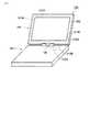
図1は、本発明の一実施形態に係る情報機器の外観を示す斜視図である。 FIG. 1 is a perspective view showing an appearance of an information device according to an embodiment of the present invention.
同図に示される情報機器は、例えばタブレットPCと呼ばれるパーソナルコンピュータである。タブレットPC200は、液晶パネル(表示部)230にタブレットを有するディスプレイユニット200がヒンジ120を介して本体に回動可能に取り付けられた構造を有する。このような構造により、ディスプレイユニット200は、ヒンジ120を軸として自由に回転することができ、例えば液晶パネル230を外側に向けてディスプレイユニット200を本体300に閉じることができる。図1においては、液晶パネル230を内側に向けてディスプレイユニット200を本体300から開いた状態(「ラップトップモード」(もしくは「通常モード」)と呼ばれるラップトップ使用形態に相当)が示されている。 The information device shown in the figure is a personal computer called a tablet PC, for example. The tablet PC 200 has a structure in which a
ディスプレイユニット200には、無線LAN用アンテナ210A,210Bが実装されている。これらのアンテナ210A,210Bは、互いに90°異なる角度で設置され、異なる偏波を受信することができる。ディスプレイユニット200を開いた状態において、アンテナ210Aは、例えばディスプレイユニット200の面上部に設けられ、一方、アンテナ210Bは、例えばディスプレイユニット200の面側部に設けられる。また、アンテナ210Aは、例えばディスプレイユニット200の表側(液晶パネル230側)に設けられ、アンテナ210Bは、例えばディスプレイユニット200の裏側に設けられる。勿論、アンテナ210Aがディスプレイユニット200の裏側に、アンテナ210Bがディスプレイユニット200の表側に設けられてもよい。アンテナ210A,210Bのうち、いずれか一方は受信および送信が可能な(即ち、電波を輻射する)送受信用アンテナであり、もう一方は受信のみを行う受信用アンテナである。以下では、アンテナ210Aが、電波を輻射する送受信用アンテナであるものとして説明する。 The
一方、本体300には、無線LANコントローラ(モジュール)310A,310Bが実装されている。また、給電ケーブル220Aがディスプレイユニット200の左側面近傍を通るようにアンテナ210Aから延び、ヒンジ120を通って無線LANコントローラ310Aに接続されている。同様に、給電ケーブル220Bがアンテナ210Bから下方向に延び、ヒンジ120を通って無線LANコントローラ310Bに接続されている。 On the other hand, the
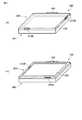
図2(a)には、液晶パネル230を内側に向けてディスプレイユニット200を本体300側に閉じた状態が示されている。なお、給電ケーブル220A、220B等の表示は省略している。一方、図2(b)には、液晶パネル230を外側に向けてディスプレイユニット200を本体300側に閉じた状態、即ち、ディスプレイユニット200の前面と対向する背面が本体300の上面と対向するように位置した状態(「タブレットモード」と呼ばれるタブレット使用形態に相当)が示されている。なお、給電ケーブル220A、220B等の表示は省略している。 FIG. 2A shows a state where the
なお、図2(a)及び図2(b)の例に示されるアンテナ210A,210Bの配置を、図3(a)及び図3(b)の例に示されるように変えても構わない。 Note that the arrangement of the
図4は、タブレットモードにおける画像表示形態の種類を説明するための図である。また、図5は、画像表示形態の種類に応じた使用形態の違いを説明するための図である。 FIG. 4 is a diagram for explaining the types of image display modes in the tablet mode. FIG. 5 is a diagram for explaining the difference in usage pattern according to the type of image display pattern.
図4に示されるように、タブレットモードにおいては液晶パネル230に表示される画像の向きによって4種類の画像表示形態が考えられる。画像表示形態は、大きく分けて「ポートレート」(縦長表示)と「ランドスケープ」(横長表示)とに分類される。 As shown in FIG. 4, in the tablet mode, four types of image display modes are conceivable depending on the orientation of the image displayed on the
図4(a)に示されるポートレートAの例ではヒンジ120が右側に位置し、一方、図4(b)に示されるポートレートBの例ではヒンジ120が左側に位置している。図5(a)には、ユーザがポートレートでタブレットPC100を使用する場合の例が示されている。 In the portrait A example shown in FIG. 4A, the
図4(c)に示されるランドスケープAの例ではヒンジ120が下側に位置し、一方、図4(b)に示されるランドスケープBの例ではヒンジ120が上側に位置している。図5(a)には、ユーザがランドスケープでタブレットPC100を使用する場合の例が示されている。 In the example of landscape A shown in FIG. 4C, the
図6は、タブレットPC100のシステム構成の一例を示すブロック図である。 FIG. 6 is a block diagram illustrating an example of a system configuration of the tablet PC 100.
タブレットPC100の本体300は、CPU111、ノースブリッジ112、主メモリ113、グラフィクスコントローラ114及びサウスブリッジ115を有する。本体300はまた、BIOS−ROM120、ハードディスクドライブ(HDD)130、光ディスクドライブ(ODD)140、LANコントローラ151、無線LANコントローラ310A,310B、カードコントローラ153、エンベデッドコントローラ/キーボードコントローラIC(EC/KBC)160、および電源回路170を有する。 The
CPU111は、コンピュータ10の動作を制御するプロセッサである。このCPU111は、ブートデバイス、例えばHDD130から主メモリ113にロードされるオペレーティングシステム(OS)を実行する。またCPU111は、各種アプリケーションプログラムを実行する。またCPU111は、BIOS−ROM120に格納されたシステムBIOS(Basic Input Output System)も実行する。システムBIOSはハードウェア制御などを行うプログラムである。 The
ノースブリッジ112は、CPU111のローカルバスとサウスブリッジ115との間を接続するブリッジデバイスである。ノースブリッジ112には、主メモリ113をアクセス制御するメモリコントローラも内蔵されている。また、ノースブリッジ112は、AGP(Accelerated Graphics Port)バスなどを介してグラフィクスコントローラ114との通信を実行する機能も有している。 The
グラフィクスコントローラ114は、液晶パネル230などを制御する表示コントローラである。グラフィクスコントローラ114はビデオメモリ(VRAM)114aを有しており、当該VRAM114aに書き込まれた表示データから、液晶パネル230に表示すべき表示イメージを形成する映像信号を生成する。 The
サウスブリッジ115は、BIOS−ROM120へのアクセスを制御する。BIOS−ROM120はフラッシュROMのような書き換え可能な不揮発性メモリである。前記したようにBIOS−ROM120は、システムBIOSを格納する。またサウスブリッジ115は、HDD130及びODD140などのディスクドライブ(I/Oデバイス)を制御する。 The
サウスブリッジ115は、PCI(Peripheral Component Interconnect)バス2及びLPC(Low Pin Count)バス3にそれぞれ接続される。サウスブリッジ115は、PCIバス2及びLPCバス3上の各デバイスを制御する。PCIバス2はシステムバスとして用いられる。 The
HDD130は、各種ソフトウェア及びデータを格納するストレージ装置である。HDD130は、モータにより回転される磁気記録メディア(磁気ディスク)へ/からのヘッド(磁気ヘッド)によるデータの書き込み/読み出しを行う。HDD130には、オペレーティングシステム(OS)が予め格納されている。OSはBIOS−ROM120に格納されているシステムBIOSに従って主メモリ113にロードされることにより、CPU111によって実行される。 The
ODD140はコンパクトディスク(CD)やデジタル多用途ディスク(DVD)のような光記録メディア(光ディスク)をモータにより回転駆動するドライブユニットである。ODD140は光ディスクから/へのヘッド(光ヘッド)によるデータの読み出し/書き込みを行う。 The
PCIバス2には、LANコントローラ151、無線LANコントローラ310A,310B及びカードコントローラ153が接続されている。LANコントローラ151は、本体300をLAN(有線LAN)に接続するためのネットワークコントローラである。無線LANコントローラ310A,310Bは、本体300を無線LANに接続するためのネットワークコントローラである。カードコントローラ153は、当該カードコントローラ153と接続されるカードスロットに挿入されたPCカード或いはSD(Secure Digital)カードのようなカードデバイスを制御する。 A
EC/KBC160は、電源管理のためのエンベデッドコントローラと、キーボード(KB)13及びタッチパッド16などを制御するキーボードコントローラとが単一チップに集積されたマイクロコンピュータである。EC/KBC160は、電源回路170と協調して動作することにより、ユーザによるパワーボタンスイッチ14の操作に応答して、コンピュータ10を電源オンする電源制御機能を有している。また、EC/KBC160は、加速度センサ15やヒンジ状態センサ11から送られる各検出信号を受け、各種の状態を示す情報をBIOS、ドライバ、もしくはOSへ通知することができる。 The EC /
加速度センサ15は、空間上の3軸方向に関して外部から与えられる加速度を検出するものである。ヒンジ状態センサ11は、ヒンジ120の状態(即ち、本体300に対するディスプレイユニット200の状態)を検出するものである。 The acceleration sensor 15 detects acceleration given from the outside with respect to three axial directions in space. The
電源回路170は、リチャージャブルなバッテリ171または高電圧電源としてのACアダプタ172を介して供給されるDC電源を用いて、本体300の各要素に印加すべきシステム電源電圧を生成する。ACアダプタ172は、AC電源をDC電源に変換する。 The
図7は、無線LANコントローラ310A,310Bに共通する構成の一例を示すブロック図である。ここでは、無線LANコントローラ310Aについてのみ説明する。 FIG. 7 is a block diagram illustrating an example of a configuration common to the
無線LANコントローラ310Aは、RF(Radio Frequency)部311、水晶発信部312、およびベースバンド処理部313を備える。 The wireless LAN controller 310 </ b> A includes an RF (Radio Frequency)
RF部311は、給電ケーブル220Aを介してアンテナ210Aから入力された高周波信号を水晶発信部312の発信周波数に基づいて低周波信号に変換し、ベースバンド処理部313に出力する。また、ベースバンド処理部313から出力されるベースバンド信号を水晶発信部312からの発信周波数に基づいて高周波信号に変換し、給電ケーブル220Aを介してアンテナ210Aに出力する。 The
ベースバンド処理部313は、RF部311から出力されたベースバンド信号にアナログ/デジタル変換を施して、CPU111が処理可能なデジタル信号に変え、バス2に出力する。また、バス2から入力されたデジタル信号にデジタル/アナログ変換を施してベースバンドのアナログ信号にし、RF部311に出力する。 The
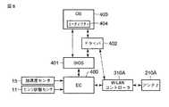
図8は、送受信用アンテナから輻射される電波の抑制制御に関わる機能構成の一例を示すブロック図である。 FIG. 8 is a block diagram illustrating an example of a functional configuration related to suppression control of radio waves radiated from a transmission / reception antenna.
EC400は、加速度センサ15から得られる加速度の情報やヒンジ状態センサ11から送られるヒンジ状態の情報を、BIOS401等を経由してOS403へ伝えることができる。なお、これらの情報は、EC400を経由せずにOS403へ伝わるように構築することも可能である。 The
BIOS401は、加速度の情報やヒンジ状態の情報などを取得し、それらをOS403へ通知することができる。 The
ドライバ402は、OS403から送信出力の停止/再開の指示があった場合にBIOS401経由でEC400へ無線LANコントローラ310Aに対する電源供給の停止/再開を要求したり、OS403から送信出力の低下/増大の指示があった場合に無線LANコントローラ310Aの送信出力を低下/増大させたりすることができる。これにより、無線LANコントローラ310Aの中のRF部331のアンプの出力が変化し、アンテナ210Aからの電波輻射が抑制されたり当該抑制が解除されたりする。 The driver 402 requests the
OS403は、BIOS40から得られるヒンジ状態の情報に基づいてタブレットPCの使用形態(タブレットモード、ラップトップモードなど)を認識したり、自身が持っている表示に関する情報に基づいて現在の表示画像の向きを認識することができる。また、取得される加速度の情報に基づいてタブレットPCの移動を認識し、表示画像の向きを適切に切り換えることができる(即ち、図4に示される4種類の表示形態のいずれかへの切り換えができる)。また、OS403は、所定の通信モジュール(3Gモジュール等)を通じてキャリア情報(接続先事業者の情報など)を得ることもできる。これらの情報はユーティリティ404に渡され、無線LANコントローラ310Aの送信出力の抑制(停止もしくは低下)の要否を判定するために使用される。 The
ユーティリティ404は、図9に示されるように、状態認識部501、送信出力制御部502、抑制要否判定部503、といった各種の機能を備えている。なお、これらの機能は全てユーティリティ404に設けられる必要は必ずしもなく、一部の機能を他のソフトウェアもしくはハードウェアが担うように構成してもよい。 As shown in FIG. 9, the
状態認識部501は、BIOS401(もしくはOS403)から得られるヒンジ状態の情報とOS403から得られる表示画像の向きの情報とに基づき、タブレットモードが形成されており且つ液晶パネル230に表示される画像の下方向にアンテナ210Aが位置する所定の状態が成立しているか否かの判定、もしくは当該状態の認識が可能である。 Based on the hinge state information obtained from the BIOS 401 (or the OS 403) and the display image orientation information obtained from the
送信出力制御部502は、上記所定の状態が認識された場合には、アンテナ210Aから電波が輻射されることを抑制する制御(例えば、輻射量を低下させる制御、輻射を停止させる制御、もしくは無線LANコントローラ310Aからアンテナ210Aへの信号送信を停止させる制御など)を実行することができる。 When the predetermined state is recognized, the transmission
抑制要否判定部503は、取得されるキャリア情報に示される接続先事業者が所定のリストに記載されているか否かを確認することにより、無線LANコントローラ310Aの送信出力の抑制(停止もしくは低下)の要否を判定することができる。この判定結果に基づいて、送信出力制御部502における制御を実行すべきかどうかを決定するように構成してもよい。 The suppression
次に、図10を参照して、送受信用アンテナから輻射される電波の抑制制御に関わる動作の一例を説明する。ここでは、ユーティリティ404の動作に関して説明する。 Next, an example of an operation related to suppression control of radio waves radiated from a transmission / reception antenna will be described with reference to FIG. Here, the operation of the
ユーティリティ404は、BIOS401(もしくはOS403)からヒンジ状態の情報を取得すると共に、OS403から表示画像の向きの情報を取得し(ステップS11)、これらの情報に基づき、タブレットモードが形成されており且つ液晶パネル230に表示される画像の下方向にアンテナ210Aが位置する所定の状態が成立しているか否かを判定する(ステップS12)。所定の状態が成立しない場合(ステップS13のNO)、アンテナ210Aの出力を通常の出力(例えば、最大出力)のままとし(もしくは、通常の出力に戻し)(ステップS14)、ステップS11からの処理を繰り返す。一方、所定の状態が成立する場合(ステップS13のYES)、取得されるキャリア情報に示される接続先事業者が所定のリストに記載されているか否かを確認することにより、無線LANコントローラ310Aの送信出力の抑制(停止もしくは低下)の要否を判定する(ステップS15)。抑制が不要である場合(ステップS16のNO)、アンテナ210Aの出力を通常の出力(例えば、最大出力)のままとし(もしくは、通常の出力に戻し)(ステップS14)、ステップS11からの処理を繰り返す。一方、抑制が必要である場合(ステップS16のYES)、電波に関連する法令に定められる基準を満たすようにアンテナ210Aの出力を低下または停止させる制御を実行し(ステップS17)、ステップS11からの処理を繰り返す。 The
このように本実施形態によれば、電波を輻射するアンテナが実装されたタブレットPCに関して、当該アンテナがユーザの体(腹部など)に接近する状況が生じたとしても、電波に関連する法令に定められる基準を満たすことができる。また、タブレットPCの移動に応じて画像表示の向きが変わったとしても、適切に輻射電波の抑制制御を行うことができる。また、接続先事業者に応じて、輻射電波の抑制制御を行うか行わないかの判断も行うことができる。 As described above, according to the present embodiment, regarding a tablet PC on which an antenna that radiates radio waves is mounted, even if a situation occurs in which the antenna approaches the user's body (such as the abdomen), the laws and regulations relating to radio waves are established. Can meet the standards. Moreover, even if the direction of image display changes according to the movement of the tablet PC, the suppression control of the radiated radio wave can be appropriately performed. Further, it is possible to determine whether or not to perform suppression control of the radiated radio wave depending on the connection destination operator.
なお、本発明は上記実施形態そのままに限定されるものではなく、実施段階ではその要旨を逸脱しない範囲で構成要素を変形して具体化できる。また、上記実施形態に開示されている複数の構成要素の適宜な組み合わせにより、種々の発明を形成できる。例えば、実施形態に示される全構成要素から幾つかの構成要素を削除してもよい。さらに、異なる実施形態にわたる構成要素を適宜組み合わせてもよい。 Note that the present invention is not limited to the above-described embodiment as it is, and can be embodied by modifying the constituent elements without departing from the scope of the invention in the implementation stage. In addition, various inventions can be formed by appropriately combining a plurality of constituent elements disclosed in the embodiment. For example, some components may be deleted from all the components shown in the embodiment. Furthermore, constituent elements over different embodiments may be appropriately combined.
100…ラブレットPC、120…ヒンジ、200…ディスプレイユニット、210A,210B…無線LAN用アンテナ、230…液晶パネル、300…本体、310A,310B…無線LANコントローラ、400…EC、401…BIOS、402…ドライバ、403…OS、404…ユーティリティ、501…状態認識部、502…送信出力制御部、503…抑制要否判定部。 DESCRIPTION OF
Claims (17)
Translated fromJapanese前記表示部に表示される画像の向きに合わせてユーザが前記情報処理装置を使用する形態において認識する当該画像の上側、下側、左側、右側のうち、下側に、前記アンテナが位置する所定の状態が成立しているか否かを、少なくとも当該画像の向きを示す情報に基づいて判定する判定手段と、
前記所定の状態が成立していると判定された場合、前記アンテナから電波が輻射されることを抑制する制御手段と、
を具備することを特徴とする情報処理装置。An information processing apparatus in which an antenna is mounted on a display unit having a display unit,
A predetermined position in which the antenna is located on the lower side among the upper side, the lower side, the left side, and the right side of the image that the user recognizes in the form in which the user uses the information processing device in accordance with the orientation of the image displayed on the display unit Determination means for determining whether or not the state is established based on at least information indicating the orientation of the image;
Control meansfor suppressing radio waves frombeing radiated from the antennawhen it is determined that the predetermined state is established ;
An information processing apparatus comprising:
前記制御手段は、前記所定の状態が成立していると判定された場合、前記無線モジュールから前記アンテナへの信号の送信を停止する手段を含むことを特徴とする請求項1記載の情報処理装置。A radio module for transmitting a signal to the antenna;
The information processing apparatus according to claim 1, wherein the control unit includes a unit that stops transmission of a signal from the wireless module to the antennawhen it is determined that the predetermined state is established. .
前記加速度センサにより検出される加速度の情報に基づいて前記情報処理装置の移動を認識し、当該情報処理装置の移動に応じて前記表示部に表示される画像の向きを切り換える切換手段と、をさらに具備し、
前記制御手段は、前記切換手段によって切り換えられた画像の下方向に前記アンテナが位置する場合、前記アンテナから電波が輻射されることを抑制することを特徴とする請求項1記載の情報処理装置。An acceleration sensor for detecting acceleration;
Switching meansfor recognizing movement of the information processing device based on accelerationinformation detected by the acceleration sensor and switching the orientation of an image displayed on the display unitaccording to the movement of the information processing device; Equipped,
The information processing apparatus according to claim 1, wherein the control unitsuppresses radio waves frombeing radiated from the antenna when the antenna is positioned in a lower direction of the image switched by the switching unit.
前記ディスプレイユニットの前面に設けられる表示部と、
前記ディプレイユニットにヒンジを介して回動可能に取り付けられる本体と、
前記ディスプレイユニットの前面と対向する背面が前記本体の上面と対向するように位置し、且つ、前記表示部に表示される画像の向きに合わせてユーザが前記情報処理装置を使用する形態において認識する当該画像の上側、下側、左側、右側のうち、下側に、前記アンテナが位置する所定の状態が成立しているか否かを、前記ヒンジの状態を示す情報と当該画像の向きを示す情報とに基づいて判定する判定手段と、
前記所定の状態が成立していると判定された場合、前記アンテナから電波が輻射されることを抑制する制御手段と、
を具備することを特徴とする情報処理装置。A display unit on which an antenna for radiating radio waves is mounted;
A display unit provided on the front surface of the display unit;
A main body rotatably attached to the display unit via a hinge;
Recognizing in a form in which the user uses the information processing apparatus in accordance with the orientation of the image displayed on the display unit, the rear surface facing the front surface of the display unit is positioned so as to face the upper surface of the main body. Information indicating the state of the hinge and information indicating the orientation of the image as to whether or not a predetermined state in which the antenna is located is established on the lower side among the upper side, the lower side, the left side, and the right side of the image Determining means for determining based on
Control meansfor suppressing radio waves frombeing radiated from the antennawhen it is determined that the predetermined state is established ;
An information processing apparatus comprising:
前記制御手段は、前記所定の状態が成立していると判定された場合、前記無線モジュールから前記アンテナへの信号の送信を停止する手段を含むことを特徴とする請求項7記載の情報処理装置。A radio module for transmitting a signal to the antenna;
The information processing apparatus according to claim 7, wherein the control unit includes a unit that stops transmission of a signal from the wireless module to the antennawhen it is determined that the predetermined state is established. .
前記表示部に表示される画像の向きに合わせてユーザが前記情報処理装置を使用する形態において認識する当該画像の上側、下側、左側、右側のうち、下側に、前記アンテナが位置する所定の状態が成立しているか否かを、少なくとも当該画像の向きを示す情報に基づいて判断し、
前記所定の状態が成立していると判定された場合、前記アンテナから電波が輻射されることを抑制することを特徴とする動作制御方法。In an operation control method applied toan information processing apparatus in which an antenna is mounted on a display unit having a display unit ,
A predetermined position in which the antenna is located on the lower side among the upper side, the lower side, the left side, and the right side of the image that the user recognizes in the form in which the user uses the information processing apparatus according to the orientation of the image displayed on the display unit. Is determinedbased on at least information indicating the orientation of the image ,
When it is determined that the predetermined state is established , the operation control method is characterizedby suppressing radio waves frombeing radiated from the antenna.
前記検出された加速度の情報に基づいて前記情報処理装置の移動を認識し、当該情報処理装置の移動に応じて前記表示部に表示される画像の向きを切り換え、
前記切り換えられた画像の向きに合わせてユーザが前記情報処理装置を使用する形態において認識する当該画像の上側、下側、左側、右側のうち、下側に、前記アンテナが位置する所定の状態が成立している場合、前記アンテナから電波が輻射されることを抑制することを特徴とする請求項12記載の動作制御方法。Acceleration is detected by an acceleration sensor included in the information processing apparatus,
Based onthe detected accelerationinformation to recognize the movement of the information processing apparatus to switch the orientation of the image displayed on the display unitin accordance with the movement of the information processing apparatus,
Upper recognizes the image in the form a user uses the information processing apparatus in accordance with the direction ofthe switchedimage, lower, left, of the right, the lower, the predetermined state in which the antenna is located 13. The operation control method according to claim 12, wherein whenthe condition is established,radio waves are prevented frombeing radiated from the antenna.
Priority Applications (4)
| Application Number | Priority Date | Filing Date | Title |
|---|---|---|---|
| JP2006052043AJP4185104B2 (en) | 2006-02-28 | 2006-02-28 | Information device and operation control method thereof |
| US11/525,342US7733275B2 (en) | 2006-02-28 | 2006-09-21 | Information apparatus and operation control method thereof |
| EP06122038AEP1826654A2 (en) | 2006-02-28 | 2006-10-10 | Information processing apparatus and operation control method thereof |
| CNB2006101366896ACN100517282C (en) | 2006-02-28 | 2006-10-30 | Information device and operation control method thereof |
Applications Claiming Priority (1)
| Application Number | Priority Date | Filing Date | Title |
|---|---|---|---|
| JP2006052043AJP4185104B2 (en) | 2006-02-28 | 2006-02-28 | Information device and operation control method thereof |
Publications (2)
| Publication Number | Publication Date |
|---|---|
| JP2007235329A JP2007235329A (en) | 2007-09-13 |
| JP4185104B2true JP4185104B2 (en) | 2008-11-26 |
Family
ID=37772602
Family Applications (1)
| Application Number | Title | Priority Date | Filing Date |
|---|---|---|---|
| JP2006052043AActiveJP4185104B2 (en) | 2006-02-28 | 2006-02-28 | Information device and operation control method thereof |
Country Status (4)
| Country | Link |
|---|---|
| US (1) | US7733275B2 (en) |
| EP (1) | EP1826654A2 (en) |
| JP (1) | JP4185104B2 (en) |
| CN (1) | CN100517282C (en) |
Families Citing this family (25)
| Publication number | Priority date | Publication date | Assignee | Title |
|---|---|---|---|---|
| US7292198B2 (en) | 2004-08-18 | 2007-11-06 | Ruckus Wireless, Inc. | System and method for an omnidirectional planar antenna apparatus with selectable elements |
| US7193562B2 (en) | 2004-11-22 | 2007-03-20 | Ruckus Wireless, Inc. | Circuit board having a peripheral antenna apparatus with selectable antenna elements |
| US7358912B1 (en) | 2005-06-24 | 2008-04-15 | Ruckus Wireless, Inc. | Coverage antenna apparatus with selectable horizontal and vertical polarization elements |
| US7893882B2 (en) | 2007-01-08 | 2011-02-22 | Ruckus Wireless, Inc. | Pattern shaping of RF emission patterns |
| JP2009152705A (en)* | 2007-12-19 | 2009-07-09 | Toshiba Corp | Electronic computer and switching circuit |
| JP2009296377A (en)* | 2008-06-05 | 2009-12-17 | Toshiba Corp | Electronic apparatus |
| WO2010005423A1 (en)* | 2008-07-07 | 2010-01-14 | Hewlett-Packard Development Company, L.P. | Tablet computers having an internal antenna |
| JP2010067225A (en)* | 2008-09-12 | 2010-03-25 | Toshiba Corp | Information processor |
| US8217843B2 (en)* | 2009-03-13 | 2012-07-10 | Ruckus Wireless, Inc. | Adjustment of radiation patterns utilizing a position sensor |
| WO2011048747A1 (en)* | 2009-10-19 | 2011-04-28 | 日本電気株式会社 | Wireless communication device |
| JP2011091744A (en)* | 2009-10-26 | 2011-05-06 | Alps Electric Co Ltd | Information processing apparatus |
| JP4810601B2 (en)* | 2009-11-30 | 2011-11-09 | 株式会社東芝 | Information processing apparatus and control method |
| JP5283762B2 (en)* | 2009-12-14 | 2013-09-04 | 富士通株式会社 | Arithmetic processing apparatus, information processing apparatus and control method thereof |
| KR101319264B1 (en) | 2010-01-22 | 2013-10-18 | 전자부품연구원 | Method for providing UI according to multi touch pressure and electronic device using the same |
| JP2011171935A (en) | 2010-02-17 | 2011-09-01 | Panasonic Corp | Communication equipment |
| JP5664443B2 (en)* | 2011-04-28 | 2015-02-04 | 富士通株式会社 | Information processing apparatus, radio wave intensity control method, and program |
| US8756668B2 (en) | 2012-02-09 | 2014-06-17 | Ruckus Wireless, Inc. | Dynamic PSK for hotspots |
| US10186750B2 (en) | 2012-02-14 | 2019-01-22 | Arris Enterprises Llc | Radio frequency antenna array with spacing element |
| US9634403B2 (en) | 2012-02-14 | 2017-04-25 | Ruckus Wireless, Inc. | Radio frequency emission pattern shaping |
| US9092610B2 (en) | 2012-04-04 | 2015-07-28 | Ruckus Wireless, Inc. | Key assignment for a brand |
| US9007179B2 (en)* | 2013-03-25 | 2015-04-14 | Panasonic Intellectual Property Management Co., Ltd. | Electronic apparatus |
| US20150171504A1 (en)* | 2013-12-13 | 2015-06-18 | Kabushiki Kaisha Toshiba | Electronic apparatus |
| CN105305017A (en)* | 2014-06-26 | 2016-02-03 | 展讯通信(上海)有限公司 | Mobile terminal |
| TWI648657B (en)* | 2017-10-23 | 2019-01-21 | 群光電子股份有限公司 | Keyboard device and system operation method |
| JP2021026546A (en)* | 2019-08-06 | 2021-02-22 | パナソニックIpマネジメント株式会社 | Convertible type notebook computer |
Family Cites Families (15)
| Publication number | Priority date | Publication date | Assignee | Title |
|---|---|---|---|---|
| JPH11186841A (en) | 1997-12-22 | 1999-07-09 | Matsushita Electric Ind Co Ltd | Transmission device and transmission method thereof |
| JPH11340845A (en) | 1998-05-28 | 1999-12-10 | Kokusai Electric Co Ltd | Portable wireless telephone |
| US6426723B1 (en)* | 2001-01-19 | 2002-07-30 | Nortel Networks Limited | Antenna arrangement for multiple input multiple output communications systems |
| JP2002261665A (en) | 2001-02-28 | 2002-09-13 | Matsushita Electric Ind Co Ltd | Portable wireless devices |
| JP2003101623A (en) | 2001-09-21 | 2003-04-04 | Kyocera Corp | Foldable portable radio |
| JP3891831B2 (en) | 2001-11-26 | 2007-03-14 | シャープ株式会社 | Portable radio |
| JP3875646B2 (en) | 2003-02-26 | 2007-01-31 | 日本航空電子工業株式会社 | 4-split key-top switch, input device, mobile phone terminal using this |
| JP4168261B2 (en) | 2003-03-11 | 2008-10-22 | 日本電気株式会社 | Mobile phone antenna and switching method thereof |
| ATE494644T1 (en)* | 2003-06-12 | 2011-01-15 | Research In Motion Ltd | MULTI-ELEMENT ANTENNA WITH FLOATING PARASITIC ANTENNA ELEMENT |
| JP2005072734A (en) | 2003-08-20 | 2005-03-17 | Nec Corp | Camera attached mobile terminal, and image display method and display control program used for the mobile terminal |
| TWM247895U (en) | 2003-12-10 | 2004-10-21 | Tatung Co | Improved frame structure in rotational display |
| JP2005227899A (en) | 2004-02-10 | 2005-08-25 | Vodafone Kk | Information communication terminal |
| KR20060123576A (en)* | 2004-02-25 | 2006-12-01 | 코닌클리즈케 필립스 일렉트로닉스 엔.브이. | Antenna Array and Its Operation Method |
| JP2005252539A (en) | 2004-03-03 | 2005-09-15 | Sharp Corp | Mobile device |
| JP4566825B2 (en)* | 2005-06-03 | 2010-10-20 | レノボ・シンガポール・プライベート・リミテッド | Method for controlling antenna of portable terminal device and portable terminal device |
- 2006
- 2006-02-28JPJP2006052043Apatent/JP4185104B2/enactiveActive
- 2006-09-21USUS11/525,342patent/US7733275B2/enactiveActive
- 2006-10-10EPEP06122038Apatent/EP1826654A2/ennot_activeWithdrawn
- 2006-10-30CNCNB2006101366896Apatent/CN100517282C/enactiveActive
Also Published As
| Publication number | Publication date |
|---|---|
| CN100517282C (en) | 2009-07-22 |
| US20070200775A1 (en) | 2007-08-30 |
| JP2007235329A (en) | 2007-09-13 |
| CN101030179A (en) | 2007-09-05 |
| US7733275B2 (en) | 2010-06-08 |
| EP1826654A2 (en) | 2007-08-29 |
Similar Documents
| Publication | Publication Date | Title |
|---|---|---|
| JP4185104B2 (en) | Information device and operation control method thereof | |
| JP5105767B2 (en) | Information processing apparatus and operation control method thereof | |
| JP4746472B2 (en) | Information processing apparatus and operation control method thereof | |
| JP5664443B2 (en) | Information processing apparatus, radio wave intensity control method, and program | |
| US20100167645A1 (en) | Information processing apparatus | |
| JP4566825B2 (en) | Method for controlling antenna of portable terminal device and portable terminal device | |
| US7773037B2 (en) | Information processing apparatus, information processing system and radio communication control method | |
| US10403960B2 (en) | System and method for antenna optimization | |
| JP4365845B2 (en) | Portable computer, screen display direction changing method, program, and storage medium | |
| JP4810601B2 (en) | Information processing apparatus and control method | |
| US8566489B2 (en) | Systems and methods for sharing a wireless antenna in a hybrid environment | |
| US20160308276A1 (en) | System and method for dynamic switching of antennas | |
| US9451565B2 (en) | Wireless communication apparatus | |
| US20140267096A1 (en) | Providing a hybrid touchpad in a computing device | |
| US20100164814A1 (en) | Information processing apparatus | |
| JP5121968B2 (en) | Information processing apparatus and operation control method thereof | |
| US8645705B2 (en) | Information processing device and activation control method | |
| US20080299924A1 (en) | Information processor and control method thereof | |
| JP2014007699A (en) | Electronic device, communication module, and communication control method | |
| JP2004054542A (en) | Information processor | |
| JP2009284525A (en) | Method of controlling antenna of mobile terminal equipment, and the mobile terminal equipment | |
| JP2008160423A (en) | Information processing device |
Legal Events
| Date | Code | Title | Description |
|---|---|---|---|
| A977 | Report on retrieval | Free format text:JAPANESE INTERMEDIATE CODE: A971007 Effective date:20080512 | |
| A131 | Notification of reasons for refusal | Free format text:JAPANESE INTERMEDIATE CODE: A131 Effective date:20080603 | |
| A521 | Request for written amendment filed | Free format text:JAPANESE INTERMEDIATE CODE: A523 Effective date:20080804 | |
| TRDD | Decision of grant or rejection written | ||
| A01 | Written decision to grant a patent or to grant a registration (utility model) | Free format text:JAPANESE INTERMEDIATE CODE: A01 Effective date:20080902 | |
| A01 | Written decision to grant a patent or to grant a registration (utility model) | Free format text:JAPANESE INTERMEDIATE CODE: A01 | |
| A61 | First payment of annual fees (during grant procedure) | Free format text:JAPANESE INTERMEDIATE CODE: A61 Effective date:20080904 | |
| FPAY | Renewal fee payment (event date is renewal date of database) | Free format text:PAYMENT UNTIL: 20110912 Year of fee payment:3 | |
| R151 | Written notification of patent or utility model registration | Ref document number:4185104 Country of ref document:JP Free format text:JAPANESE INTERMEDIATE CODE: R151 | |
| FPAY | Renewal fee payment (event date is renewal date of database) | Free format text:PAYMENT UNTIL: 20110912 Year of fee payment:3 | |
| FPAY | Renewal fee payment (event date is renewal date of database) | Free format text:PAYMENT UNTIL: 20110912 Year of fee payment:3 | |
| FPAY | Renewal fee payment (event date is renewal date of database) | Free format text:PAYMENT UNTIL: 20120912 Year of fee payment:4 | |
| FPAY | Renewal fee payment (event date is renewal date of database) | Free format text:PAYMENT UNTIL: 20120912 Year of fee payment:4 | |
| FPAY | Renewal fee payment (event date is renewal date of database) | Free format text:PAYMENT UNTIL: 20130912 Year of fee payment:5 | |
| S111 | Request for change of ownership or part of ownership | Free format text:JAPANESE INTERMEDIATE CODE: R313121 Free format text:JAPANESE INTERMEDIATE CODE: R313117 | |
| R350 | Written notification of registration of transfer | Free format text:JAPANESE INTERMEDIATE CODE: R350 |