JP4184612B2 - Gas flow control method for gas-assisted ESU - Google Patents
Gas flow control method for gas-assisted ESUDownload PDFInfo
- Publication number
- JP4184612B2 JP4184612B2JP2000616687AJP2000616687AJP4184612B2JP 4184612 B2JP4184612 B2JP 4184612B2JP 2000616687 AJP2000616687 AJP 2000616687AJP 2000616687 AJP2000616687 AJP 2000616687AJP 4184612 B2JP4184612 B2JP 4184612B2
- Authority
- JP
- Japan
- Prior art keywords
- gas
- flow
- flow rate
- signal
- flow path
- Prior art date
- Legal status (The legal status is an assumption and is not a legal conclusion. Google has not performed a legal analysis and makes no representation as to the accuracy of the status listed.)
- Expired - Lifetime
Links
- 238000000034methodMethods0.000titledescription92
- 238000009297electrocoagulationMethods0.000claimsabstractdescription19
- 230000005540biological transmissionEffects0.000claimsdescription18
- 230000000977initiatory effectEffects0.000claimsdescription15
- 230000004044responseEffects0.000claimsdescription11
- 230000036961partial effectEffects0.000claimsdescription5
- 230000000740bleeding effectEffects0.000claimsdescription4
- 230000002829reductive effectEffects0.000abstractdescription30
- 208000005189EmbolismDiseases0.000abstractdescription2
- 239000007789gasSubstances0.000description284
- 238000009530blood pressure measurementMethods0.000description55
- 230000006872improvementEffects0.000description21
- 230000010102embolizationEffects0.000description18
- 230000002496gastric effectEffects0.000description18
- 239000000523sampleSubstances0.000description16
- 239000008280bloodSubstances0.000description15
- 210000004369bloodAnatomy0.000description15
- 238000012546transferMethods0.000description15
- 230000009471actionEffects0.000description14
- 230000006870functionEffects0.000description9
- XKRFYHLGVUSROY-UHFFFAOYSA-NArgonChemical compound[Ar]XKRFYHLGVUSROY-UHFFFAOYSA-N0.000description8
- 238000010586diagramMethods0.000description8
- 238000001356surgical procedureMethods0.000description8
- 206010039509ScabDiseases0.000description7
- 230000008901benefitEffects0.000description7
- 238000005259measurementMethods0.000description7
- 206010001526Air embolismDiseases0.000description6
- 230000015271coagulationEffects0.000description6
- 238000005345coagulationMethods0.000description6
- 230000009467reductionEffects0.000description5
- 229910052786argonInorganic materials0.000description4
- 230000008859changeEffects0.000description4
- 230000007423decreaseEffects0.000description4
- 230000000694effectsEffects0.000description4
- 238000007789sealingMethods0.000description4
- 230000009286beneficial effectEffects0.000description3
- 230000023555blood coagulationEffects0.000description3
- 210000000170cell membraneAnatomy0.000description3
- 230000003247decreasing effectEffects0.000description3
- 238000001514detection methodMethods0.000description3
- 230000002401inhibitory effectEffects0.000description3
- 230000007246mechanismEffects0.000description3
- 230000003287optical effectEffects0.000description3
- 238000012360testing methodMethods0.000description3
- 210000000683abdominal cavityAnatomy0.000description2
- 210000003815abdominal wallAnatomy0.000description2
- 230000033228biological regulationEffects0.000description2
- 239000004020conductorSubstances0.000description2
- 230000001276controlling effectEffects0.000description2
- 238000010891electric arcMethods0.000description2
- 206010053567CoagulopathiesDiseases0.000description1
- 206010052428WoundDiseases0.000description1
- 208000027418Wounds and injuryDiseases0.000description1
- 230000006399behaviorEffects0.000description1
- 238000005452bendingMethods0.000description1
- 238000007664blowingMethods0.000description1
- 238000006243chemical reactionMethods0.000description1
- 230000035602clottingEffects0.000description1
- 230000003111delayed effectEffects0.000description1
- 238000002674endoscopic surgeryMethods0.000description1
- 210000003238esophagusAnatomy0.000description1
- 239000012530fluidSubstances0.000description1
- 238000011902gastrointestinal surgeryMethods0.000description1
- 239000007943implantSubstances0.000description1
- 239000011261inert gasSubstances0.000description1
- 238000002347injectionMethods0.000description1
- 239000007924injectionSubstances0.000description1
- 230000001788irregularEffects0.000description1
- 238000002357laparoscopic surgeryMethods0.000description1
- 238000002324minimally invasive surgeryMethods0.000description1
- 238000012986modificationMethods0.000description1
- 230000004048modificationEffects0.000description1
- 238000002355open surgical procedureMethods0.000description1
- 238000011017operating methodMethods0.000description1
- 230000008520organizationEffects0.000description1
- 230000035479physiological effects, processes and functionsEffects0.000description1
- 230000001737promoting effectEffects0.000description1
- 230000001105regulatory effectEffects0.000description1
- 210000002784stomachAnatomy0.000description1
- 230000000007visual effectEffects0.000description1
- 230000029663wound healingEffects0.000description1
Images


Classifications
- A—HUMAN NECESSITIES
- A61—MEDICAL OR VETERINARY SCIENCE; HYGIENE
- A61B—DIAGNOSIS; SURGERY; IDENTIFICATION
- A61B18/00—Surgical instruments, devices or methods for transferring non-mechanical forms of energy to or from the body
- A61B18/04—Surgical instruments, devices or methods for transferring non-mechanical forms of energy to or from the body by heating
- A61B18/042—Surgical instruments, devices or methods for transferring non-mechanical forms of energy to or from the body by heating using additional gas becoming plasma
Landscapes
- Health & Medical Sciences (AREA)
- Surgery (AREA)
- Engineering & Computer Science (AREA)
- Life Sciences & Earth Sciences (AREA)
- Medical Informatics (AREA)
- Molecular Biology (AREA)
- Nuclear Medicine, Radiotherapy & Molecular Imaging (AREA)
- Plasma & Fusion (AREA)
- Biomedical Technology (AREA)
- Heart & Thoracic Surgery (AREA)
- Physics & Mathematics (AREA)
- Otolaryngology (AREA)
- Animal Behavior & Ethology (AREA)
- General Health & Medical Sciences (AREA)
- Public Health (AREA)
- Veterinary Medicine (AREA)
- Surgical Instruments (AREA)
- Pipeline Systems (AREA)
- Plasma Technology (AREA)
- External Artificial Organs (AREA)
Abstract
Description
Translated fromJapanese【0001】
本発明は米国特許第4781175号に開示されている特許の結果として開拓されたタイプのガスアシスト式電気手術に関する。さらに詳細に述べると、本発明はガスアシスト式電気手術で使用されるガスの流れをガス流量と背圧に対して制御する新しくかつ改良された方法と装置に関する。本発明の改良点の意義はガス塞栓の危険性および不適当な手術状態が生じる可能性がある環境を減らすことである。
【0002】
(発明の背景)
ガスアシスト式電気手術は組織から流れる血液を手術部位で凝固するか止めるために使用される。ガスアシスト式電気凝固には電気エネルギーのアークおよび組織へ流れるガス流中のイオン化された導電性経路を伝達することが含まれる。このガス流は組織から流れた血液を取り除き、電気エネルギーのアークが直接組織内に入って組織内部で網状組織を作ることを可能にする利点がある。この網状組織は内部で血液が自然に凝固するマトリックス状の構造を形成し、これによってこの組織を封止してそれ以上出血するのを止める。非常に重要な利点はガスアシスト式電気手術のこの形態によるものである。血液の凝固がより迅速に起きる。以前は血液の凝固が不可能あるいは実施困難であったような状態でも凝固が可能である。手術中に失われる血液の量が少なく、かつ手術の手順がより迅速に終了する。かさぶたとして知られる組織表面の封止が完璧であるため手術終了後の再出血の可能性がほとんど無くなる。このかさぶたは、標準の、ガスを使用しない電気手術の方法を使用して得られたかさぶたと比べてより薄くより均一であるため、傷の治癒がより早くなる。
【0003】
ガスアシスト式電気凝固の数多のかつ重要な利点にも係わらず、その使用についてある懸念が生じていた。恐らく重大な懸念の多くは患者体内のガス塞栓の危険性に関するものである。ガス塞栓とは患者の血液の流れの中にガスが導入されることである。もし血液流中のガスの量がかなり有りそれが心臓に蓄積されると、心臓はもはや血液を送り出すことが出来なくなる。適切に使用されるのであれば、ガスアシスト式電気凝固は迅速に血液を凝固させかなりの量のガスを導入する前に組織を封止する能力を持っているため安全な方法である。ガス塞栓が起こる可能性がある環境を避ける際の外科医の技量、およびガスアシスト式電気凝固で使用される機器の品質がガス塞栓の危険性に影響する可能性がある。
【0004】
ガス塞栓を避ける非常に有効な方法の1つは、信頼性のある方法でかつ組織から十分に距離をあけてガス流中のアークの伝達を開始することであり、そこでは組織に対するガスの影響で過剰な量のガスが組織内に押し込まれることはないが、しかし依然としてガスが血液を追い出して他の流体が組織の表面や細胞膜上に蓄積する原因となる。米国特許第4781175号および登録第34432号はそのような距離で電気的アークが確実に開始する技法を記述している。
【0005】
他のタイプのガスアシスト式電気凝固装置は、発電機とは別のガス供給装置と組み合わせた、標準的な、ガスを使用しないタイプの電気手術用発電機を使用している。これらを組み合わせた装置は一般的に、標準の電気手術用発電機が通常使用される静止空気の環境でアークを開始するために利用できる能力以上のアーク開始能力はまったく持っていない。静止空気の環境でアーク伝達を開始することは、流れるガスの環境でアーク伝達を開始することに比べ問題点が少ないが、これは流れるガスがイオン化種を分散させて組織へのアーク伝達の開始を難しくさせる傾向があるためである。標準の電気手術用発電機を発電機とは別のガス供給装置と組み合わせた場合は、組織へのアーク伝達の開始を非常に困難あるいは不可能にさせ、ガスの流れがアークまたはイオン化種の「吹き消え」を起こし易い。このアーク伝達を開始する時の問題点を打ち消すための対応として、当然ながらアプリケータ装置のガス供給ノズルを組織のごく近くに持ってくることが考えられる。このことによって、近くに位置することから本質的にもたらされる背圧の結果として、ガスの流れが遅くなる。ガスの流れを減らした状態では、標準の電気手術用発電機がアーク伝達を開始するのがより容易になる。いったんアークが開始されると、それらを維持することはさらに容易であり、外科医はアプリケータを手術する距離まで引き出すことができる。しかしながら、近接した作動距離でアーク伝達を開始することに関連したガス塞栓の危険性を避けるために外科医にはあるレベルの技量と理解が要求される。外科医のすべてがこの能力を持っている訳ではなく、あるいはガスアシスト式電気手術の誤った使用によるガス塞栓の可能性を理解している訳ではない。
【0006】
胃腸手術、内視鏡を用いた手術および腹腔鏡を用いた手術などの侵襲性を最小にする手術でガスアシスト式電気手術を使用することが多くなっているため、アプリケータのガスノズルの位置決めの問題が最近重要視されるようになってきている。侵襲性を最小にするガスアシスト式電気手術においては、比較的長いチューブ状のアプリケータが切り口を開くことなく患者の体内に挿入される。外科医が手術部位を目で見るために小型カメラまたは光学レンズも同様に患者体内に置かれる。電気手術用アプリケータがいったん適当な位置に配置されると、このチューブ状アプリケータの端部のノズルからガスと電気エネルギーが供給され手術部位で凝固を達成する。
【0007】
ガスアシスト式電気手術は、色々な困難な条件で行う事ができ、また同様の条件下で標準の、ガスを使用しない電気手術の方法で良好な凝固を達成するために必要な配置に関する制御度合いや精度を必要とせずに行う事のできる非常に有効な凝固法であるので、この方法は侵襲性を最小にする手術において有利であると考えられる。小型カメラおよび光学レンズによって外科医が利用できる一元的な視野では手術部位および組織に対するアプリケータの位置を目に見えるようにすることは非常に困難であるため、配置の問題は特に重要である。言い換えると、手術部位を一元的に見る場合は外科医にとって奥行きの感覚に対する便宜が無く、このため位置決めをすることが非常に難しくなる。実際、外科医がアプリケータのノズルを組織に接触させるかまたは埋め込むことをしそこなうことは珍しいことではない。このような状態は、ガスが直接組織内部に入る可能性があるためにガス塞栓の危険性の大きなきっかけとなる。ノズルが組織から適当に距離をとって配置されるような条件では、ガスアシスト式電気手術からより均一な凝固効果が得られるため、外科医が入手できる位置に関する認識が不足している状態を補ってくれる。
【0008】
本発明に含まれるのはこれらおよびその他の考え方である。
【0009】
(発明の概要)
本発明より得られる改良点の1つは、ガス塞栓の危険性を増加させることなくより信頼性の高いアーク開始を達成するようにガスの流量を自動制御することである。本発明の態様によれば、ガスアシストによる電気手術の外科医によって選択された比較的高流量のガスは、アーク伝達を開始するために自動的かつ一時的に比較的低流量に低減される。いったんアークが始まれば、ガス流量は自動的に調整されて元の希望する高流量に戻され、その結果、この選択されたガス流量で通常のガスアシストの電気手術操作が進行出来る。アーク開始を目的としたガス流量を自動的に低減することによって、アーク開始の条件がより信頼でき、かつ米国特許第4781175号および登録第34432号に開示されているようなアーク開始向上のために採用される電気出力制御技法と合わせて用いた場合でも変わらないことが確実になる。この改良は、標準的な、ガスを使用しない電気手術用発電機をこれとは別のガス供給装置と組み合わせるこれらのタイプのガスアシスト式電気凝固において特に重要である。ガス流量が低い方がアーク伝達開始の助けになるので、初めはガス流量を減らすこの改良によって標準の電気手術用発電機はより確実にアーク伝達を開始することができる。そのうえ、アーク開始中にガス流量が少ないと、高流量のガスが近接した距離で組織に影響を与える環境と比べて塞栓を起こす危険性が減少する。
【0010】
アーク開始中のガス流量を低減する改良は手術の侵襲性を最小にするのに特に有益である。このノズルが組織に近い位置に置かれるか組織内に埋め込まれるならば、初めに供給されるガス流量がより少なくなりアーク開始中のガス流量が低減されてガス塞栓の危険性が減少する。アーク開始中の流量を低減することによって閉塞がそこに存在するかどうかを危険性の少ないガス流量でチェックできる。もし閉塞があれば低い流量が維持されるかまたはアラームが設定されガスの流れも抑止される。
【0011】
アーク開始中にガス流量を低減する改良は、これらの、標準的な、ガスを使用しない電気手術用発電機をこれとは別のガス供給装置と組み合わせるガスアシスト式電気凝固システムにおいても重要である。これらの組み合わせタイプのシステムの多くは、標準的な、ガスを使用しない電気手術用発電機がアーク開始に対処する電力を調整する設備を持っていなかったため、これまでアーク開始能力を向上するような能力をまったく持っていなかった。本発明の改良点はガス供給装置に組み込むことができ、その結果、標準的な、ガスを使用しない電気手術用発電機と組み合わせて使用した場合に、組み合わせたシステムではガス塞栓の危険性を減らして組織にアーク伝達を開始する能力が向上することになる。
【0012】
本発明より得られる他の改良点の1つは、部分的な閉塞が起きているような環境下でガス流量を自動的に低減する能力に関する。一般的には、部分的な閉塞は組織に近すぎるかまたはそれに埋め込まれているアプリケータのノズルが原因になる。外科医がこのノズルを組織の内部または組織に非常に近付けて動かす結果、このような部分的閉塞がこの手順の過程中にアーク伝達が開始される前後で発生する可能性がある。このような環境はガス塞栓の危険性をも生み出す可能性がある。本発明の態様によれば、ガス供給管内の背圧が感知されそれが所定の値を超えた場合、通常の操作ガス流量は、ガス塞栓の危険性を増加させることがなさそうな背圧の許容レベルになるまで一定量ずつ低減される。閉塞が消失してその結果背圧が減少すれば、ユーザ要求の操作ガス流量が得られるかまたは背圧許容値と一致する最大ガス量が得られるまでガス流量が自動的に増加方向に一定分量調整される。背圧を継続的に評価しガス流量を増減両方向に調整するこの改良はさらに、外科医が選択した希望操作条件に戻る可能性を保持しつつガス塞栓の危険性を低減することに役立つ。
【0013】
本発明より得られる他の改良点の1つは、特定のタイプのアプリケータに伴う背圧を感知し、ガス流量をそのタイプのアプリケータの許容値に調整することに関する。ガス流量を異なるタイプおよび範疇のアプリケータに適した操作範囲に調整することで、さらに、そのタイプのアプリケータの流れの状態が、アークの開始時とアプリケータの継続使用時の両方で組織に対するアーク開始を促進しガス塞栓の危険性を低減するのに最大限貢献することがより確実になる。
【0014】
本発明より得られるさらに他の改良点は、すべての操作条件の基で背圧を感知し、重大な危険状態が起きた場合は組織に送るガスの移送および電気エネルギーの伝達を抑止することに関する。組織に送るガスおよび電気エネルギーの移送を抑止することによって、外科医は矯正的処置を取ることを余儀なくされる。
【0015】
本発明とその範囲、および上記述の改良点を達成する方法のより完全な理解は、以下に簡単に要約した添付図および添付した特許請求項に関連した以下の本発明の好ましい実施形態の詳細説明を参照することで得られる。
【0016】
(詳細な説明)
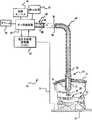
本発明を実施するガスアシスト式電気手術ユニット(ESU)は一般に図1の参照番号40で示される。このESU40は3つの主要構成要素、たとえば切開手術で用いるペンシル型のハンドピースまたは侵襲性を最小にする手術で用いるチューブ状プローブなどのアプリケータ42、ガス供給装置44および電気手術用発電機(ESG)46を含む。ガス供給装置44およびESG46は米国特許第4781175号に記述されるように組み合わせて単一ユニットにすることができ、あるいは米国特許第5041110号および同5330469号に記述されるようにそれらそれぞれ(44および46)を別々に分けるが動作可能なように相互に接続することもできる。柔軟性のあるコード48によってガス供給装置44とアプリケータ42が接続される。ESG46は高周波(RF)電気エネルギーをガス供給装置44に供給するために接続され、ESG44からの電気エネルギーがガス供給装置44を通ってコード48に伝えられる。アプリケータ42が侵襲性を最小にする手術用プローブの場合は、柔軟性のあるコード48としてプローブ自体のチューブ状の部分を延長に使用することができる。
【0017】
ガス供給装置44はコード48内の導管50を通して所定流量のガスをアプリケータ42に供給する。ガスはアプリケータ42の末端に配置されたノズル52から方向を定めた流れあるいはほぼ層流または噴流54として噴出する。ESG46によって供給される電気エネルギーはガス供給装置44を通って伝わり、コード48の導管50内に配置された導線56によって伝導される。この導線56はノズル52内に配置される針状の電極58に電気的に接続される。ESG46によって供給された電気エネルギーは電極58の回りおよびノズル52を通って流れるガスをイオン化し、噴流54中にイオン化された導電性の経路を生成する。ガス供給装置44、コード48およびノズル52は噴流54中で所定のガスを伝導する手段の一例である。ESG46、コード48および電極58はガス噴流54中のイオン化された導電性経路内で電気エネルギーを伝達する手段の一例である。
【0018】
ESU40の操作動作モードにおいて、電気エネルギーは噴流54中のイオン化された導電性経路内をアーク60の形態で伝達される。アーク60は電気手術部位にいる患者の組織62に到達するまで噴流54内部を移動する。噴流54からのガス流は蓄積している血液を組織62の表面または細胞膜から押し除け、これによって電気アーク60が導電性の血液中に拡散されることなく、組織62に入ることが可能になる。この電気アークはアークが組織62内に生成した孔を持つ網状組織64を作る。血液の自然凝固メカニズムは網状組織64によって活性化され、このことによって血液が凝固し、それ以上の出血を止め、その組織を塞ぐ。この組織の表面または細胞膜の封止凝固層は「かさぶた」として知られるものを形成する。ガスアシスト式電気手術によって作られたタイプのかさぶたの特性の詳細、およびガスアシスト式電気手術の重要な利点については米国特許第4781175号にさらに具体的に開示されている。
【0019】
アーク60の電気エネルギーはガス噴流54を通って組織62へ、そしてこの組織を通って戻り電極または患者の組織62に接触する患者プレート70に移動する。患者プレート70は返り電線72によってESG46に接続される。ESG46からの電流をノズル52の電極58に伝え、噴流54を通して組織62に、組織62を通して患者プレート70に、さらに返り導線72を通して元のESG46に伝えるために完全な電気回路が確立される。電気エネルギーがアプリケータから患者の組織を通り、手術部位から離れた所に配置される戻り電極に流れるこのタイプの回路接続は、一般に「一極性」電気手術と呼ばれる。
【0020】
組織に電気手術用の電力供給するために外科医がESU40を始動すなわち「キーを押す」と、ガス噴流中のイオン化された導電性経路が最初に確立される。ガス噴流54中のイオン化された導電性経路のイオン化状態が噴流内にコロナまたはグロー放電を発生し、またこのグロー放電またはコロナは、外科医がノズル52を操作可能な組織62の近傍に移動した時にアークの伝導を開始する事が出来る。ノズル52が操作可能な組織の近傍の位置にある場合は、組織62に至るイオン化された導電性経路が、組織62に至る噴流54の中でアーク伝達を始めるあるいは開始するのに十分な組織62を通る閉回路を確立する。ガスをガス噴流54の中で十分にイオン化種を発生する十分にイオン化された状態に保持しないと、ガス噴流54中のアーク60の組織への伝達を繰り返し、かつ確実に開始することは不可能かあるいは非常に困難である。ノズル52を通るガスの流量が比較的高流量であると、ガス噴流中のイオン化された導電性経路を維持して組織へのアーク伝達を確実にかつ安定して開始することが困難になり、このことは特に低出力で比較的高負荷のインピーダンス中にかなりの電力を伝導する能力が低下したESG46について言える。
【0021】
ESG46には、外科医が供給する電気エネルギーの量と状態を選択するための従来からあるダイアルと制御セレクタ74が含まれる。この従来からあるダイアルと制御セレクタ74は、ESG46およびガス供給装置44が単一のユニットに収納されている場合にも含まれる。同様に、ダイアルと制御セレクタ74は、外科医が手術部位に供給するガスの流量を選択できるガス供給装置44の一部を成す。表示装置76は他の情報とともにガスの流量を表示する。76に表示されるガス流量はESU40の使用中に、ノズル52から出る流れの状態の違いを反映して変化する可能性がある。制御セレクタ74は、外科医がESU40始動のために押す従来からのスイッチ(足踏みおよび指操作)の代りとすることも意図している。始動スイッチを解除するとESUの動作が停止し、ガスおよび電気エネルギーの流れが止まる。
【0022】
ガスアシスト式電気手術は、開放切開が行われ組織が開放大気に晒される切開手術の状態で行われる可能性がある。このような環境下では、外科医は一般にペンシル型のアプリケータ42を手に持ち、それを組織に対して移動して血液凝固を達成する。大抵の場合、この切開手術の手順によって手術部位または組織に対するノズル52の相対的な位置を見ることが難しくなることはない。しかしながら、激しく出血している状況の中で、外科医はノズル52を迅速に溜まる血液の中に挿入し、そのノズルの組織からの距離を計ることが出来ないことがある。患者の生理機能が不規則であるかまたは異例の個所を切開するような環境下では、外科医は組織に対するノズルの位置を定めるのに目に見えないように定めることが要求される可能性があり、このことによってノズルの組織からの相対的な位置を計ることが困難になる。このような環境下で、ノズルが組織に対して配置され、組織がこのノズルを部分的に閉塞させる可能性があり、ガス塞栓の危険性が増加する。
【0023】
侵襲性を最小にする手術条件の下では、直接に立体像を見ることが出来ない手術部位を目に見えるようにすることはさらに困難である。図1は、腹壁78を通して挿入されたアプリケータ42のノズル52を図示して侵襲性を最小にする手術状態を示している。従来の腹腔鏡を用いる手術状況の詳細すべてが示されているのではないが、腹壁78は腹腔80内に供給された吹き込みガス圧力によって組織62から離されて保持される。外科医が手術部位を見る小型カメラ(図示せず)も腹腔80内に挿入される。この吹き込みガス圧力は障害または抵抗になり、ノズル52から供給されるガスの流れはこれらを克服する必要がある。このようにして、腹腔鏡を用いる状況では、吹き込みガス圧力がガス噴流54の流量特性を制限したりあるいは変えたりし、このことは特に質量流量調節弁ではなく減圧弁がガス流量を制御している場合に言える。質量流量調節弁は背圧の影響が少ない質量流量に基づいてガス流量を供給する。この結果、質量流量調節弁式ガス供給装置44は部分的に閉塞した状況またはノズル52が組織62に対して近接した位置にあるような状況でもガスの供給を継続する可能性が高い。減圧弁システムは背圧がかかる条件下では供給されるガス流量が低下し易いが、減圧弁システムは他の環境におけるほどには正確または確実ではない。
【0024】
アプリケータ42およびノズル52が患者の体内に挿入されているという意味で、内視鏡を用いる手術の状況もまた図1に示す。内視鏡の利用においては、通常、光学レンズシステム(図示せず)がプローブアプリケータ42の一部を成す。図1はまた、プローブアプリケータ42が、通常、食道や胃などの標準的な体の通路内に挿入されることを除けば胃腸内手術の状況も表わしている。内視鏡利用および胃腸の手術部位は通常吹き込みガスによる加圧を行わない。
【0025】
本発明は、ガス供給装置44が色々な手術上の電気手術の条件の下でかつガス供給装置44に取り付けるアプリケータ42のタイプに応じてガス流量を自動的に調整する能力に焦点を当てている。本発明の対応型のガス流量の調整特性は、外科医の技量に関係無くガス塞栓の危険性を最小にするのに特に有用である。本発明の流量調整特性は異なったタイプのアプリケータ42に対し最善の操作条件を制定するのにも役立つ。本発明のガス供給装置40は、操作手順を継続することが不適当なガスの流れ状態の下ではガスの移送および電気エネルギーの伝達も終了させる。これらの状態下では、ガス供給装置44はアラーム82を作動させこれらの状態を外科医に知らせる。このガス供給装置のガスの流れの調整特性は、元来は標準の、ガスを使用しない電気手術用を意図したタイプのESG46と共に使用するガスアシスト式電気凝固用に特に使用されるESG46と共に使用する場合に利用できる。標準の、ガスを使用しない(非ガス)ESG46と共に使用すると、ガス塞栓の危険性を増加させる可能性がある電気手術の条件を制御する改良された能力が得られる。
【0026】
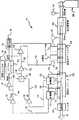
ガス供給装置44の詳細について図2を参照して説明する。ガス供給装置44はガス流路98から調節されたガス質量流量を生成し、このガスはコード48の導管50に供給され、ノズル52(図1)に導かれる。この質量流量の調節は閉ループ制御システムを用いて達成され、そこではユーザ要求の質量流量が質量流量測定値と比較され、比較結果の差に関してエラー信号が発生して、制御ループが安定するまでガス流路98中のガス流量が調整される。
【0027】
ガス供給装置44にはガス源100、圧力調整器102、空気式マニホルド104、感知オリフィス106およびフィルタ108が含まれる。ガス源100は、圧力調整器102にガスを供給する初期に約3000psiに加圧されたアルゴンガスの従来のタンクで良い。本発明では電気手術における医療用途のRFエネルギーでイオン化できるアルゴンガス、または他の不活性ガスを供給している。圧力計110は好ましくはアルゴンガス源100と圧力調整器102の間に介在させガスタンク中の残余ガス量を表示させる。圧力調整器102はガス源100からの圧力を低圧に、好ましくは約20〜30psiに減少させ、低圧ガスを空気式マニホルド104に提供する。圧力調整器102の2次側すなわち出力側には、フェールセーフ機構として出力側に接続した圧力逃がし弁(安全弁)112を設置することが好ましい。圧力逃がし弁(安全弁)112は、圧力調整器102がその出口側の圧力を下げそこなった場合に約50psiの圧力で開く。
【0028】
空気式マニホルド104は流路98のガス質量流量を制御し、一定にするための電気制御式の弁114および116を含む。この空気式マニホルド104はソレノイド弁114を含み、この弁はESU40(図1)が使用のため動作している時はいつでも開放され、またESU40が動作を停止しているときはいつでも閉止されることが好ましい。比例弁116は流路98に供給されるガス質量流量を一定にする。比例弁116は制御信号(156)が印加される結果として、ガス流量を増加させたり減少させたりする。比例弁116からの流れの変動の結果として発生する可能性があるガス流量の細かな変動または振動を緩和するために流れダンパー(図示せず)を任意選択で、比例弁116の下流に設置することができる。
【0029】
感知オリフィス106は、感知オリフィス106の入口120から取り出した圧力を感知オリフィス106の出口122の圧力に低減する較正された流れ絞り部118を含む。感知オリフィス106の前後を横切る差圧は質量流量制御ループで使われるガス流量制御情報の基礎となる。入口120と出口122の間の感知オリフィス106前後の差圧は、流路98内のガス流量に比例する。流量が増加すると較正された流れ絞り部118前後で測定される差圧を増加させ、流量が減少すると較正された流れ絞り部118前後で測定される差圧を減少させる。差圧変換器132に差圧情報を提供するために、較正された流れ絞り部118の両側の入口120および出口122にそれぞれホース124および126が接続される。第3のホース128が較正された流れ絞り部118の下流位置で絶対圧変換器134に接続される。この絶対圧変換器134は初め感知オリフィス106下流の流路98内の大気圧に対する圧力情報を提供する。初めに、ガスが流路98を通って流れる前に、ESU40が使用される海抜に対応した大気雰囲気空気圧力が第3のホース128を通して変換器134で感知される。この大気圧情報は供給されるガス量を高度の違いに応じて補正するために使用される。この高度に関連する信号は以下において参照(またはRef)信号と呼ばれる。ガスが流路98を流れる場合は、絶対圧力変換器134が流路98内のガス背圧を測定する。
【0030】
フィルタ108が感知オリフィス106下流のガス流路98内に備えられ清浄なアルゴンガスをコード48、ノズル52、および組織62に確実に供給する(図1)。コネクタ(図示せず)がガス流路98中のガスをコード48の端部に結合する。ESG46からの電気エネルギーもこの同一のコネクタ(図示せず)を通してコード48の導管50内に配置される導線56に結合されることが好ましい(図1)。
【0031】
差圧変換器132は、感知オリフィス106における流れ絞り部118前後の差圧に比例する出力電圧信号を信号線130で供給する。差圧変換器132からの130における電圧信号は増幅器138に供給され、この増幅器は130における電圧信号を増幅しdP(差分圧力)と呼ばれる出力電圧を信号線140で供給する。140におけるこのdP信号は感知オリフィス106を通るガスの流量に比例する。
【0032】
絶対圧力変換器134は、較正された流れ絞り部118の下流で感知された絶対圧力に比例する出力電圧信号を信号線136で供給する。この136における信号は、ガスが流路98を流れる間アプリケータによって引き起こされるか、組織に対するアプリケータの位置によって引き起こされるかまたは閉塞によって引き起こされる背圧に比例する。絶対圧力変換器134からの136における電圧信号は増幅器142に供給され、この増幅器は電圧信号を増幅しPABS(絶対圧力)と呼ばれる出力電圧を信号線144で供給する。信号線144のPABS信号は変換器134によって感知された絶対圧力に比例する。
【0033】
各信号線140および144の各出力電圧信号dPおよびPABSは、2つの信号140および144を掛け合わせるアナログ掛け算器146に供給される。掛け算器146からの信号線148における掛け算で得られた積の出力信号は、流路98を通って導かれるガスの質量流量測定値に直線的に比例する。信号140で表わされるものと信号144で表わされる絶対圧力の信号148で表わされる流量測定値に対する関係は良く知られている。したがって、148における出力信号は流路98を通って流れるガスの質量流量測定値を表わしている。
【0034】
PABS電圧信号は入力信号として増幅器147へも供給される。増幅器147からの出力信号は149で流路98を通って流れるガスの背圧測定値に関係した、あるいは流路98を通って流れるガスが無い時は大気圧に関係した電圧信号(PMEA)として供給される。この149におけるPMEA信号は1つの入力信号として制御ループマイクロコントローラ150に印加される。アナログ−ディジタル変換器(図示していないがこのマイクロコントローラ150内部に含まれる)が、マイクロコントローラ150で使用するためにこのPMEA電圧信号をディジタル信号に変換する。
【0035】
マイクロコントローラ150はフローコントロールセレクタ74に接続されて外科医からの始動要求を含む種々のユーザ要求の入力信号を受信する。153における信号は外科医が選ぶユーザ要求のガス流量に関係する。
【0036】
マイクロコントローラ150は151における表示流量出力信号(VGAS)を設定するが、これは初めは153におけるユーザ要求の入力信号によって設定される。この151における信号VGASは表示された流量と呼ばれ、この信号は表示装置76でユーザに提示される。安全かつ正常な操作においては、表示流量信号(VGAS)は本質的に153におけるユーザ要求の信号によって表わされる値に対応する。しかしながら、以下に述べるような環境下で、151における表示流量信号VGASは、149における背圧測定値信号PMEAの値に応じてマイクロコントローラ150の動作によって変更されることがある。このような環境下では、表示装置76に表示されるVGASの量はユーザ要求信号153で表わされる量と異なってくる。VGAS信号はマイクロコントローラ150内部に含まれるディジタル−アナログ(D/A)変換器(図示せず)によって生成されるアナログ信号である。
【0037】
アナログ掛け算器146からの148における質量流量測定値出力信号は増幅器152によって増幅され、155で得られた信号が151で差分増幅器154によってVGASと比較される。このようにして、VGAS信号で表わされる表示流量は155で質量ガス流量測定値信号と比較される。この質量ガス流量測定値信号と表示流量信号の差はどれでも差分増幅器154によって供給される156における制御信号によって表わされる。この156における制御信号によって比例弁116が設定する流量へ調節され、これによって比例弁116を通るガス流量の増減を行う。測定された流量(信号155)が表示流量(信号151)を超える場合は、比例弁116に配送された制御信号156がガス流量を低減する。逆に、測定された流量が表示流量より少ない場合は、制御信号156が比例弁116に流路98を通るガス流量を増加させる。質量ガス流量測定値は手術部位の流れの状態の違いによって変化するので、前述の制御ループは、ユーザ要求または許容ガス流量に対応する安定状態ガス流量が得られるまで156における制御信号を変更することになる。従来のエミッターフォロワ回路(図示せず)は制御信号156を受信し制御信号156の値と関連して比例弁116へ送る電流を駆動する。
【0038】
測定された背圧(PMEA)が定義された限界条件を超える場合は、ESUの操作モードおよびそのモードのガス流量設定値に従って是正処置および操作抑止処置が取られる。これらの機能を得るために背圧信号PMEA149はマイクロコントローラによってモニタされている。もし背圧が所定アラーム限界を超えていると、ガス供給装置44の運転が停止され、ソレノイド弁114および比例弁116が閉止されてガスの供給が終了する。危険な閉塞状態が起きた場合は、ガス流路98を通るガス流量およびESG46(図1)からのRF電気エネルギーの供給をそれぞれ終了させ、装置の停止を引き起こした条件について、アラーム82(図1)から外科医に耳に聞こえる警告(ビーッという音またはトーンなど)を与え、また目に見える表示(エラーコードまたはメッセージ)を表示装置76上に与えることが好ましい。危険性の少ない部分閉塞、一時的なわずかな閉塞およびその他のある制御条件は流路98に供給されるガス流量の低減をもたらす。
【0039】
ガス流量は質量流量閉ループの調節によって制御されているので、閉塞によってノズル52からのガスの流れが阻害されるような場合でもガス流量を維持しようとする。このような環境下では、本明細書で説明したガス流量の調節機能なしでは、塞栓あるいはその他の危険な状態が存在している可能性がある。このため、背圧が所定の限界を超える場合は、ガス流路98内の背圧自体がガスが流れるライン内の閉塞あるいはその他の制約を予想し、ガスの質量流量を制御するのに使用される。この所定の背圧限界はガス供給装置のそれぞれに異なる各操作モードに特有のものであり、またすべてを外科医が選択する種々のユーザ要求ガス流量設定値に関係している。
【0040】
ガス供給装置44を最初にオンにしたとき、149におけるPMEA電圧信号が読み取られマイクロコントローラ150のメモリ内に格納される。この初期値は参照(Ref)電圧またはこの手順の継続期間、および以下に述べるようなESUの操作モードに関連した他の目的のための信号として使用される。さらに、各設定値またはESUから供給されるガス流量の許容操作範囲内の流量に対して、PMEA電圧は設定された参照電圧に加えられる特定の増分値であると予想される。各流量におけるこのPMEA信号の予想された増分値は経験的に決定され、ガス供給装置44に使用されている各構成要素の特性に関係している。各流量に対する予想増分値は、以下に述べる各操作中に使用するためにマイクロコントローラ150に関連したメモリ内に格納される。
【0041】
本発明から得られる改良点の1つは、ESG46がアーク開始を向上するために電力供給について特定の変更を行う能力を持っていないような状態の下でも、ガス噴流54中のアーク伝達エネルギーの組織への開始をより確実に行うことを容易にすることに関係する。この改良は、アーク伝達を開始するために組織の近くにノズル52(図1)を持ってくる必要があるこれらの環境下ではガス塞栓の危険性を避けるために特に有用である。このような環境下で、連続的に電気凝固を行うために比較的高いガス流量が選択される状況でノズルを組織に近付けることはガス塞栓の危険性を高める可能性がある。
【0042】
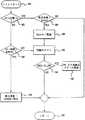
一般的に言えば、ESUが始動した後アーク開始を向上させるためおよびガス流量を減らした危険性の少ない状態下で閉塞を検出させるため、ガス流量は一時的に流量が低減される。アーク伝達が開始され閉塞がまったく感知されなかった後、ユーザ要求の比較的高いガス流量が自動的に供給される。この特別な機能性について図3を参照して説明し、本明細書では「ソフトスタート」と呼ぶ。
【0043】
図3に示される「ソフトスタート」手順はマイクロコントローラ150(図2)内に含まれる教育用コードによって実行される。このソフトスタート操作フローはステップ180から始まり、ESUの始動と共に始まる最初の期間中に適用される。マイクロコントローラ150は、コントロールセレクタ74(図2)からの信号の1つとして外科医からの始動要求を示す信号を受信する。この始動要求に応じて、スタートタイムクロックが初めに稼動する(図示せず)。この後直ちにステップ182で、現在の状態はソフトスタート手順の始まり、すなわちゼロ時間なのかどうかについて判定がなされる。もしそうであれば、ステップ184で表示流量(初めはユーザ要求流量と同じ)が2標準リットル/分(slpm)より大きいかどうかの判定がなされる。もしそうであれば、ステップ188に示すように測定されたガス流量が2slpmに低減される。
【0044】
流路中の閉塞のテストはこの後ステップ188で開始される。背圧信号が所定のアラーム限界(AL_LIM)を超えるかどうかを判定するために、背圧信号PMEA(149、図2)がステップ190でテストされる。図3を参照したこの所定のアラーム限界AL_LIMはステップ186で設定された流量2slpmが許容値である可能性がある経験的に定義された最大背圧限界である。背圧がこの所定アラーム限界を超えていると、ステップ192に示すように許容できない背圧条件が存在し、アラーム状態が開始される。ステップ192で開始されたアラーム状態と共に、ステップ192に示すようにESG46(図1)からの電気エネルギー(RF)およびガス供給装置44(図1、2)からのガス流量が停止され、これによってESUの動作が停止する。ESU40がステップ192でいったん動作を停止されると、閉塞の原因が確定され是正された後、ESUを継続して使用するためにもう1回再度始動要求を行う必要がある。
【0045】
ステップ190の判定がノーであれば、測定された背圧信号(PMEA)が所定アラーム限界(AL_LIM)より小さいことを示し、この手順の流れはステップ194に進み、次いでステップ190から手順開始ステップ180に戻る。さらに、ステップ184で表示流量が2slpmより小さいという判定であれば、流量は組織への良好なアーク伝達を開始するのに十分低く、そのためプログラムの流れはステップ194に進む。ソフトスタート手順の流れの1つのループすなわち実行は100ミリ秒ごとに発生する。
【0046】
ソフトスタート手順の流れ全体の第2およびその後のループについては、始動のタイムクロック(図示せず)が、ステップ182でなされる判定によってプログラムの流れがステップ196の判定に進む時点まで進行している。ステップ196において、このタイムクロックが、600ミリ秒を超えているかどうかが判定されるが、これは図3に示す手順を通るおおよそ6回のループで生じる時間である。ステップ196の判定がノーであれば、ステップ188で閉塞のテストが始まり、続いてその後のステップ190および192によって表わされる機能が実行される。もしステップ196の判定がイエスであれば、ステップ198に示されるようにユーザ要求の流量の値(153、図2)が表示される。これ以降、プログラムの流れはステップ194に進む。
【0047】
図3に示すソフトスタートコントロール手順全体の最初の段階を超えたその後の各段階について、背圧アラームおよび装置停止の各条件はまったく存在しないと想定して、このソフトスタート手順スタート後の経過時間が600秒以下の場合はプログラムフローはステップ196からステップ188、190および194に進み、したがって100ミリ秒間隔でソフトスタート手順の他の実行に戻る。図3に示すプログラムフローを十分な回数ループした移行が行われかつステップ196の判定がイエスであれば、その後ステップ198でガス流量が表示装置76(図1および2)に表示されるユーザ要求ガス流量に設定される。このようにして、ステップ198の実行と共に、ソフトスタート手順の中で一時的に低減されたガス流量の設定値は、それ以降以下に述べる他の制御要因が間に起こらなければ、その後ユーザが要求したガス流量に設定される。
【0048】
ステップ184で最初に低ガス流量を設定することによりアーク伝達の開始が促進される。このアーク伝達は直ぐにかさぶたを生成し始めるが、このかさぶたはガスの注入に抗して組織を捜し求め、またこの傷口の封止作用は比較的多量のガスが供給される場合も継続する。この低減した開始流量のガスが供給される時間幅は限られており、これによる電気凝固効果への制約は外科医が望む完全な効果から見ても一時的でごくわずかなものに過ぎない。低減した開始流量のガスが組織から血液を直ぐには取り除かなくても、非常に迅速に起きるより高流量のガスがこれを行うことになる。もし何らかの理由でソフトスタートシーケンスの最後でアーク開始が始まらなかった場合は、外科医が全量で供給することは問題であると認識するようになり、この問題の時に外科医はESUの動作を停止させ、是正処置が取られた後にもう1回始動シーケンスで開始する必要がある。
【0049】
ソフトスタートの改良は、ガス供給装置と組み合わせて標準の非ガスタイプの電気手術用発電機を使用するこれらの組み合わせ型ガスアシスト式の各ESUにおいて特に有用であり有益である。ガス流量を制御することで得られる改良された開始能力は、アーク伝達を開始するためのESGの電気および出力特性を変えるだけで過去において得ることのできたユティリティの改善とも同等になっている。標準的な非ガス電気手術用発電機は、ガスアシスト式電気手術についてアーク開始のため電気出力特性を変更する能力は持っていなかったため、すべてではないにしろ、大抵のこのような組み合わせ型ガスアシスト式各ESUは、アーク開始特性が改良されることはなかった。本発明のこの改良はESGの出力特性を変更することなくこのような改良されたアーク開始特性を提供する。
【0050】
ソフトスタート手順(ステップ184、図3)が、最初に閉塞が存在していたかどうかを判定し、実際の要求流量でガスを流す前に閉塞を取り除くことを可能にするのに十分である間に初期の低流量が設定される。ガス供給装置を始動するのとほとんど同時にガス塞栓の状態が発生する可能性があり、ソフトスタート手順はこのような状態を検出することを考慮にいれている。この期間中の閉塞に対してPMEA電圧(149、図2)がサンプリングされる。閉塞に対応してガスの流れを停止する前に2つの作用が感知と応答の遅延を発生させる可能性がある。最初の遅延作用はガス流路98(図2)内に背圧を蓄積するのに必要な時間量である。この最初の遅延は取り付けるアプリケータのタイプおよび要求の流量に依存するだろう。2番目の遅延はある最小値を予想するために計画的に選ぶことができるが、応答処置が取られる前の閉塞の存在に対する安全期間である。この2番目の遅延によって流れ上に時々起こるわずかなまたは一時的な制約を無視することが可能になる。
【0051】
ソフトスタートのために選択された期間はすべてのケースの閉塞を検出するには十分ではないかもしれないが、ソフトスタートは依然として比較的高いガス流量を患者に供給することによって引き起こされる塞栓の危険性を最小にすることができる利点を提供することができる。高流量でガスを流し始める前に、低流量でガスの通路を予備加圧し、これによって、高流量で閉塞が検出される前の高流量でガスが供給される時間数を減らす。このやり方では、一部の時間に対して患者に偶然に低流量の開始流量で流れが供給され、後でガス流量が非常に多くなる前にESU40が装置停止されることがある。予備加圧は変換器132および134(図2)にも圧力を供給し、その結果、より高い要求ガス流量を最小限にあるいはソフトスタート時間が終了した時の行き過ぎもせずに調整し安定化することができる。
【0052】
このソフトスタート手順は好ましくは以下に述べる操作モードの流れチェック手順すべてに組み込まれる。ソフトスタート手順は以下に述べるガスフローの調整手順の前に行われるべきであるので、ソフトスタート手順は以下に述べる流れチェック手順の初めに置くことが好ましい。しかしながら、図6と合わせ以下に説明する手動操作モードの流れチェック手順は非常に短いため、図6に示すこの流れチェック手順の後にソフトスタート手順を置くことも許容できる。
【0053】
本発明の改良点の1つに、背圧を感知してガス供給装置に接続するアプリケータのタイプを決定することがある。この改良は侵襲性を最小にするアプリケータ(内視用または胃腸内用)をいつ取り付けるかを決定する時に特に有益である。本発明のこの特別な態様の機能性は、以下において手術の「内視」モードと呼ばれ、図4A、4Bおよび4Cでさらに徹底的に説明される。内視モードは最大許容流量を4標準リットル/分(slpm)に制限している。したがって、内視モードに対する流量範囲は0.1slpmから4slpmであり、ユーザが選択した出力設定値に基づくユーザ選択最大および最小流量限界によって設定される。
【0054】
胃腸内(GI)電気手術プローブ類は、この内視モードで使用されるタイプのアプリケータの例であり、約1.5mmから約3.4mmの範囲にわたる外径によって特徴づけられる。内径は外径より25%から35%小さくてもよい。これらのアプリケータは非常に低い流量でも1ポンド/(インチ)2(psi)も過剰に背圧を生ずる可能性があり、4slpmの流量で6psiもの高い背圧を生ずる可能性があり、したがって閉塞の挙動に似ている。このように高い背圧はノズル52のオリフィス(図1)における流速を増加させ、これによってアーク開始不良を起こし、あるいはアーク伝達および作動距離を短くする可能性がある。
【0055】
内視モードで操作している場合は、制御マイクロコントローラ150はPMEA信号(149、図2)の最大限界を設定することになり、この限界を超える場合は流量が2slpm以下に低減されることになる。この制御マイクロコントローラ150は制御信号156(図2)を変えることにより流量を低減する。流量を低減することによって、背圧が低減されノズル52のオリフィスにおけるガス流速が低減されることになり、容易にイオン化とアーク伝達ができる。下の表1に流量低減および閉塞アラームの各処置に対して設定された例示的な限界を示した。
【表1】
PMEA信号が、設定された参照電圧(Ref)にたとえば約0.3V(ガス供給装置44で使用される機器の特性に応じて実験的に導かれた値)のような適当なGI参照余裕分を加えたものより大きい場合、取り付けられたアプリケータはGIプローブであると仮定する。GI参照余裕分はGIプローブの背圧を内視鏡プローブと識別する。GIプロープ用の希望流量設定値が2slpmを超える場合は、ESUの始動毎に流量が自動的に2slpmまたは1.5slpmに低減される。しかしながら、出力設定が高すぎる場合には高電力で電極を損傷しないように注意する必要がある。始動要求が終わると流量が元の設定に戻るが、ESUが動作を停止されているためガスは流れない。
【0057】
表1は代表的な流量範囲に対して取られる処置の一例を示している。この流量はPMEA信号が規定の値を超えた場合、処置の欄に示されるように低減される。設定された参照電圧(Ref)は一般的に2V〜2.6Vの範囲にある。マイクロコントローラ150(DIAL)によって設定された表示流量の各範囲に対して、最大PMEA信号が示されており、これを超えると閉塞アラーム処置か、ガス流量低減処置のどちらかが発生する。ガス流量低減処置に対して、ガス流量はたとえば0.5slpmなどの適当な刻みで低減される。好ましい実施形態においては、ガス流量はたとえば現行のRF作動のため1段階だけ減少される。閉塞アラーム処置に対しては、ガス流量が抑止されるだけではなく、電気エネルギーの供給も停止されESUの動作が停止される。
【0058】
この例では、たとえば約1.0slpm未満などの低い範囲の希望流量に対し、PMEA信号が設定された参照電圧に約0.3Vのような適当な折り返し余裕分を加えたものより大きい場合は流れを低減する処置が実行され、そこでは低減された時の流量が適当な最小値、たとえば約0.1slpm以上である限り、表示流量が適当な量、たとえば約0.5slpmだけ低減される。しかしながら、PMEA信号が設定された参照電圧に約0.5Vのような適当な閉塞余裕分を加えたものより大きい場合は閉塞アラーム処置が実行される。たとえば約1.0slpmと約1.5slpmの間の中間範囲の希望流量に対し、PMEA信号が設定された参照電圧に約0.6Vのような適当な折り返し余裕分を加えたものより大きい場合は流れを低減する処置が実行されるが、PMEA信号が設定された参照電圧に約1.2Vのような適当な閉塞余裕分を加えたものより大きい場合は閉塞アラーム処置が実行される。たとえば約1.5slpmを超える適当な高い範囲の希望流量に対し、PMEA信号が設定された参照電圧に約0.7Vのような適当な折り返し余裕分を加えたものより大きい場合は流れを低減する処置が実行されるが、PMEA信号が設定された参照電圧に約1.3Vのような適当な閉塞余裕分を加えたものより大きい場合は閉塞アラーム処置が実行される。
【0059】
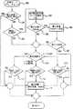
図4A、4Bおよび4Cは内視モードにおける例示的なガス流量調整手順の流れ図を構成している。この流れチェック手順はたとえばおおよそ100ミリ秒毎などの適当な間隔で実行される。マイクロコントローラ150(図2)はステップ200でこの手順に入り、ステップ201に移ってそこで表示流量がユーザ要求設定値より小さいかどうかを判定する。このステップ201は、この手順がそれ以降の流量低減ステップを複数回実行することを防ぎ、そのためステップ201での答えがイエスであれば、手順は図4Bに示すステップ220に分岐する。もしステップ201での答えがノーであれば、次にステップ202でPMEA信号が許可されたGI参照余裕分(GI_REF)を超えているかどうかが判定される。もし超えていなければ、この手順はステップ210に分岐する。しかし、もしGI参照余裕分を超えているようであれば、その後、ステップ204でGIプローブのインジケータフラッグ(GI PROBE)がオンになり、この手順がGIプローブの存在を仮定していることが示され、タイマがゼロに初期化され、そのため適当な時間間隔の後に閉塞の検出手順を行うことができる。その後ステップ206で、この手順は表示流量がたとえば約2.0slpmなどの最大値より大きく設定されているかどうかを判定するが、これを超えていればGIプローブを操作するのに不適当であろう。もし超えていれば、ステップ208で表示流量がGIプローブの最大許容ガス流量(約2slpmなど)にリセットされる。次にステップ207で、ユーザ選択の出力が所定の最大値(たとえば約80W)より大きいかどうかを判定するが、これを超えていてもしガス流量が非常に低く設定されているとアプリケータ電極が損傷を受けるであろう。もしそうであれば、制御フローは図4Bに示されるステップ220へ分岐する。好ましい実施形態においては、内視モードは単に、いったんガス流量減少させ次にその流量を元のユーザ要求の設定値(図4C、ステップ232参照)に戻すのに適した条件となるまでその流量をその値に保持するだけである。ステップ206または207での判定がノーであればステップ208で実際の流量を変更しないで制御フローは直接ステップ210へ進む。
【0060】
ステップ210から始まって、もし背圧が非常に高いがESUを停止する程には高くない場合は、ガス流量を低減するために各ステップが実行される。ステップ210では、表示流量の範囲が判定される。表示流量がたとえば約1.0slpm未満などの適当な低い範囲にある場合、この手順はステップ212で、PMEA信号が設定された参照電圧にたとえば約0.3Vなどの適当な低位折り返し余裕分を加えた低位折り返し参照電圧(LOW FB_REF)より大きいかどうかを判定する。表示流量がたとえば約1.0slpm以上、約1.5slpm未満の中間範囲にある場合、この手順はステップ214で、PMEA信号が設定された参照電圧にたとえば約0.6Vなどの適当な中間の折り返し余裕分を加えた中間折り返し参照電圧(MED FB_REF)より大きいかどうかを判定する。表示流量がたとえば約1.5slpm以上の高い範囲にある場合、この手順はステップ216で、PMEA信号が設定された参照電圧にたとえば約0.7Vなどの適当な高位折り返し余裕分を加えた高位折り返し参照電圧(HIGH FB_REF)より大きいかどうかを判定する。もしステップ212、214および216でチェックされた条件が真であると判定されると、この条件は背圧が高すぎることを示しており、そのため比例弁116を制御するマイクロコントローラ150によって与えられた表示流量がたとえば0.5slpm(ステップ218)のような適当な量だけ低減され、制御が図4Bに示すステップ220に移る。ステップ212、214および216でチェックされた条件が真でないと判定された場合は、背圧は許容できるので実流量設定に対する調整はなんら行われず、制御は直接図4Bに示すステップ220に移る。
【0061】
図4Bに示されるステップ220から始まって、背圧が非常に高くて閉塞のような危険性の高い状態が発生する場合は、手順はESU40を停止する各ステップを実行する。ステップ220で、この手順はたとえば約200ミリ秒などの適当な時間間隔(TIMER)が経過したかどうかを判定し、その結果、ESU40の完全な停止はそれほど急激には起こらず、これによって装置停止前に一時的な閉塞の問題を是正する時間を与えている。もし200ミリ秒を超えていればタイマをリセットする事が好ましい。もしそうでなければ、閉塞はたぶん一時的であり手順は分岐して図4に示す手順の閉塞検出の終了点に進む。ステップ220で設定した適当な時間間隔が経過した場合、この手順はステップ222で表示流量の範囲を判定する。表示流量がたとえば約1.0slpm未満などの低い範囲にある場合、この手順はステップ224で、PMEA信号が設定された参照電圧にたとえば約0.5Vなどの適当な低位閉塞余裕分を加えた低位アラームトリップ参照電圧(LOW_TRIP POINT)より大きいかどうかを判定する。表示流量がたとえば約1.0slpm以上、約1.5slpm未満の中間範囲にある場合、この手順はステップ226で、PMEA信号が設定された参照電圧にたとえば約1.2Vなどの適当な中間閉塞余裕分を加えた中間アラームトリップ参照電圧(MED_TRIP POINT)より大きいかどうかを判定する。表示流量がたとえば約1.5slpm以上の高い範囲にある場合、この手順はステップ228で、PMEA信号が設定された参照電圧にたとえば約1.3Vなどの適当な高位閉塞余裕分を加えた高位アラームトリップ参照電圧(HIGH_TRIP POINT)より大きいかどうかを判定する。このアラームトリップ参照電圧は、これを超えると閉塞アラームを設定する必要があるカットオフ点であり、そのためもしステップ224、226および228でチェックされた条件が真であると判定されると、この条件は背圧が非常に高く閉塞がESU40の安全な動作を妨げている可能性があることを示しており、したがってこの手順はESU40の動作を停止して閉塞アラーム状態を示しながら流れ限界エラーを設定し(ステップ230)、表示装置76およびアラーム装置78(図1)においてユーザにアラームと表示装置による表示を与える。この後、制御フローは図4Cに示すステップ232に移る。ステップ224、226および228でチェックされた条件が真でないと判定された場合は、閉塞状態が無いと仮定され、制御が直接図4Cに示すステップ232に移る。
【0062】
図4Cに示すステップ232では、手順は表示された流量を元のユーザ要求の設定値に戻すことが適当かどうか判定する。ステップ232では、PMEA信号が、設定された参照電圧にユーザ要求の設定値に起因する予想増加分を加え実験的に確立された安全値である約19mVなどの適当な余裕分を差し引いたV_USER_REQ信号より小さいかどうかが判定される。ステップ232ではまた表示された流量が、PMEA信号と同等の現行予想流量より大きいかどうかが判定される。このステップ232の答えがイエスであれば表示流量がユーザ要求設定値に設定され、GIプローブ信号がオフ(ステップ234)にされてこの手順が終了する(ステップ236)。ステップ232の判定の際、そうでない場合は、設定値を元の値に再調整することなくこの手順が終了する。
【0063】
図4A、4Bおよび4Cに示される背圧測定値(PMEA)の最大限界は単に例示的な例である事、また経験または実験の結果によって、別の応用では別の限界値がより適当である事を示す可能性があることが理解される。さらに、別の応用では異なった背圧条件に対する異なった応答がより適当であると分かるかもしれない。
【0064】
切開手術の手順ではESUの自動的操作モードが第1に選択され、そこでは一般的に10slpmまでのガス流量が使用される。本明細書では「自動」モードと呼ばれる自動的モードは内視モードがESU40のガス流量または運転をそれぞれ低減または完全に抑止したのと本質的に同じ原理で運転される。自動モードには外科医が流量を手動調整しないで単に希望の出力レベルを設定し、ESU40に流量を適当に自動調節させるあらゆる状況が含まれることが理解されるが、自動モードにおいては、ガス流量はESU40の出力設定値に対して調節される。
【0065】
自動モードでは、背圧の測定値を限定された限界および適当な限界内に保持しようとするために、ガス流量を低減する、または1リットル増分して「折り返す」ことが好ましい。他の実施形態または他の応用において各ステップの大きさを変えたものやあるいはガス流量を連続的に調整するものでも使用することができる。流量を4slpmあるいは何か他の適当な最小値以上に低減することも好ましい。このため、もし希望する流量設定値が10slpmであれば、この流量は6slpmの量だけ低減することができる。最小流量に到達し、最大圧力限界になった場合は、アラームが設定されESU40の動作が停止される。
【0066】
それぞれのユーザ要求設定値に対し、流量が折り返される限界は、PMEA信号が設定された参照電圧にユーザ要求設定値によって示される予想される増加分を加え、さらに実験的に決定された適当な折り返し余裕分を加えたものを超える場合などの、本質的に同じポイントで起きることが好ましい。そのような適当な余裕分は、マイクロコントローラ150(図2)のアナログ−ディジタル(A/D)変換の回数で約3回で良く、これはA/Dの3倍の分解能である。閉塞アラームはPMEA信号が、約3.3Vのようなあらゆる流量における絶対最大値を超えるかまたはPMEA信号が設定された参照電圧にユーザ要求設定値による予想増加分を加え、さらにA/Dの約10回数などの適当な閉塞余裕分を加えたものを超える場合にもたらされる。閉塞アラームは、伝達されたRFエネルギーおよびガスの流れを抑止することによってESU40を効果的に装置停止することが好ましい。この閉塞アラーム状態はアラームが実際に生じる前に適当な長さの時間保持されなければならないかもしれない。
【0067】
たとえば、制御マイクロコントローラ150(図2)のアナログ−ディジタル変換器(図示せず)の分解能はA/D1回またはビット当たり約0.02Vで良い。この例として、表2は4〜10slpmの各ユーザ要求設定値に対する典型的な予想限界および折り返し限界を示している。この例では表示流量の下限は4slpmであると仮定している。折り返し電圧は、Refに各ユーザ要求設定値の予想電圧を加算したものより3回数または約0.06V高い。表示流量が折り返された後、この手順はPMEA信号が新しい折り返し限界を超えたかどうかを見るためにチェックされる。折り返し後にPMEA信号が元のユーザ要求設定値においてこの折り返し限界と比較されることが好ましい。言い換えると、この例では、元のユーザ要求設定値が10slpmであれば、各折り返しが発生した後PMEA信号の次のチェックが実際のPMEA信号を10slpmのユーザ要求設定値に対する折り返し限界である2.45Vと比較する。閉塞アラームが設定されるPMEAに対する最大電圧は、Refに各ユーザ要求設定値の予想電圧を加算したものより約10回数または約0.2V高いものとして示される。
【表2】
自動モードの流れチェック手順は図5に示す流れ図によって示される。この流れチェック手順はたとえばおおよそ100ミリ秒毎などの適当な間隔で実行される。マイクロコントローラ150はステップ250でこの手順に入り、表示流量がたとえば本例の約4slpmなどの所定の最小値より大きいかどうかの判定に移る(ステップ252)。この例では、自動モード手順に対するこの最小流量は4slpmであると仮定される。ステップ252での答えがノーであれば、制御はステップ262に分岐しそこで閉塞状態が存在するかどうかを判定するチェックが始まる。そうでない場合は、この手順は、PMEA信号が設定された参照(Ref)電圧にユーザ要求設定値によって示されるRef電圧に対して予想される増加分を加え、さらに適当なオフセットを加えた適当な折り返し限界(FB_LIM)より大きいかどうかを判定することによって、表示流量を減少させる(ステップ254)必要があるかどうかをチェックする。この例では、オフセットは約59mV、またはPMEA信号をマイクロコントローラ150に供給するアナログ−ディジタル変換器の3回計数分である。この手順は、最後のフローチェックが行われて以降適当な時間間隔(DELTA TIME)が経過し、その結果、それ以前のガス流路中の流れの変化をすべて安定化させるのに十分な量の時間が経過することをチェックして確認する。この例では、この時間間隔は0.25秒として示されるが、どのような適当な値でも良い。この時間間隔をカウントするクロック(刻時機構)は流量が変わるごとにリセットされる。ステップ245の答えがイエスであれば、この手順は表示流量をたとえば約1slpmなどの適当な所定量だけ低減する(ステップ256)。ここに示すように、このステップはガス流量を指定した最小値、この例では約4slpm以下に下げる事は許可しない。しかしながら、もしステップ254で答えがノーであれば、この手順はガス流量を増加させてそれを元の値近くに戻す条件が適正かどうかをチェックする(ステップ258)。
【0069】
折り返しは特定のアプリケータについて起こる可能性があり、特に標準的ではないノズル、小さなノズル、または長さが長くて流れが制限されるようなアプリケータについて起こり易い。これらのタイプのアプリケータは元のユーザ要求設定値からの流れの折り返しを引き起こす。流量を低減するの増分数は通常初期のユーザ要求設定値に依存する。たとえば、流量は比較的低い初期ユーザ要求設定値において単に1区間、または1slpmだけ低減することができるが、この流量は比較的高い初期ユーザ要求設定値においてたとえば約4slpm(4つの1slpm区間)の多い流量を低減しても良い。言い換えると、あるアプリケータは初期のほどほどの流量または低流量において使用できるが、流量が多いと流れアラームや閉塞アラームの原因となり、このケースでは使用のために手動モードの操作が選択されるべきである。
【0070】
ステップ258で、フロー手順は、たとえばこの例では約0.5秒の適当な時間間隔(DELTA TIME)が経過したことを再度確認する。たとえば、この手順は、ガス流量がこの例では3区間、または約3slpm低減されているケースにおいて流量を元の設定値に戻すのに約1.5秒を要する。また、表示流量と同等な電圧は、設定された参照電圧にユーザ要求の設定値による予想増加分を加え、約39mV(またはA/D変換器2回数)などの適当な余裕分を差し引いたものより小さくなければならない。もしステップ258における答えがイエスであれば、背圧条件が表示流量をユーザ要求設定値に向けて一区間戻して増加する条件に合っており、この例の手順はステップ260において表示流量を1slpmだけ増加させ、ステップ262に進む。そうでない場合は、手順がステップ262に直接つながり閉塞状態のチェックを始める。
【0071】
ステップ262で、この手順は、PMEA信号が設定された参照電圧にユーザ要求の設定値による予想増加分を加えさらに適当な閉塞余裕分を加えた閉塞アラームトリップ限界(AL_TRIP)より大きいかどうかを判定し、この閉塞アラームトリップ限界を超えていると閉塞が起きると予測される。この例では、この余裕分は約0.2V、あるいはA/D変換器の10回分として示される。もし答えがイエスであれば、この手順はステップ266で回数(閉塞回数)を増やし、閉塞回数が3を超えているかどうかをチェックする(ステップ268)。このやり方では、この例示的な流れチェック手順は約100ミリ秒に1回実行されるので、ステップ262でイエスという答えを引き起こした閉塞状態は、閉塞アラームが実際に設定される以前に約300ミリ秒間存在していなければならないことになる。この遅延はESU40の動作停止が閉塞によって早くなり過ぎるのを防止し、閉塞を取り除く時間を与える。いったん閉塞の計数が3回を超えれば、この手順がRF信号およびガスの流れを抑止することによりESU40の作動を停止し流れアラームを表示する(ステップ270)。もしステップ262でこの条件が閉塞の可能性を示していなければ、手順は閉塞計数回数をゼロにリセットする(ステップ264)。この手順はステップ272で終了する。
【0072】
この明細書で示したガス流れの調整の技術と装置の他の応用は、好ましくはガス流量を増加または減少させる必要があるかどうかあるいはESU装置の動作を停止させる必要があるかどうかを判定するために異なったパラメータをチェックする必要があることを理解すべきである。上の例で示したパラメータは単に説明の目的で示したものであり、本発明の範囲を制限しようとするものではない。
【0073】
手動モードのESU操作では、ユーザすなわち外科医が直接実際の流量をコントロールし、そのため背圧があまりにも高い状態の場合でも自動モードの場合のようにガス流量が自動的に減少することはない。それどころか、手動モードでは重大な状態になる可能性を防止するために閉塞の検出、アラームの設定およびESU40の作動停止を行うだけである。表3は、PMEA信号が特定のユーザ要求の設定に対して示されるPMEA最大限界を超える場合にアラームを設定する手動モードの例を示している。ガス流路の最大限界における代表的配管圧力も示される。手動モードは要求の流量設定値にかかわらず適用される適当な最大PMEA信号限界(たとえば約3.3Vなど)を有することもまた好ましい。
【表3】
図6は、手動モードによる流れチェック手順の例を示している。この手順は、約100ミリ秒毎などの適当な間隔で実行するのが好ましい。制御マイクロコントローラ150はステップ300でこの手順に入り、ステップ302において、PMEA信号が最大許容限界より大きいかどうかのチェックに移るが、この最大許容限界には閉塞状態の可能性に対する2つの条件がある。すなわち、PMEA信号がすべての要求される流れの設定値に対する最大許容限界(この例では約3.3V)より大きいかどうかと、PMEA信号が設定された参照電圧に表示流量による予想増加分を加え、さらに適当な閉塞余裕分(この例では約0.78V)を加えたものより大きいかどうかの2つである。もし、どちらか1つの条件が真であれば、この手順はRF信号およびガスの流れを抑止することによりESU40の作動を停止し、最終ステップ(ステップ312)に分岐する前に流れのアラーム(ステップ304)を表示する。ステップ302で答えがノーであれば、好ましい実施形態においては、この手順はステップ306でチェックしてソフトスタート手順が(図3)がまだ有効かどうかを判定する。もしそうであれば、その後、表示された流量をユーザ要求の設定値に増加させるソフトスタートを許可する前に、この個所には全く閉塞が存在しないことを確認することが好ましい。このチェックによって、外科医が、ガスがより高流量で供給される前に閉塞状態を是正する機会がより多くなる。こうすることにより、ステップ308では、PMEA信号が、設定された参照電圧に表示流量による予想される増加分を加え、A/D変換器の約3回数などの適当な余裕分を加えたものなどの適当なテスト限界より大きいか否かが判定される。このステップ308の答えがイエスであれば、ソフトスタート手順が表示流量をより大きな値にリセットすることができないようにステップ310で表示流量が2slpmに設定される。もしステップ306またはステップ308のどちらかに対する答えがノーであれば、この手順はステップ312で終了する。
【0075】
ESU40の手動操作モードに対して本明細書で述べたガス流量調整の方法と装置の別の応用においては、他の操作パラメーターを設定するのが好ましいと判定される可能性があることが理解される。また、本明細書で述べた内視、自動および手動の各モードの他に他の操作モードを本明細書で述べたガス流量調整の方法と装置を用いて使用することができる。したがって、上に挙げた例は単に説明のためにのみなされたものであって発明の範囲を限定しようとするものではない。
【0076】
前述の例示的な操作モードは特に手術処置中の安全に関してガス流量調整の装置および方法の利点を説明している。内視モードおよび自動モードにおいてガスの流量を減らすステップによって手術処置中の塞栓の危険性は著しく減少する。さらに、流量を低減すると、過大な加圧状態が突然発生したりあるいはESU40の動作が停止される前に一時的な閉塞状態を取り除く機会が与えられ、このためこれらの改良点が外科医の技量を補うのに役立つだけではなく、機器動作停止に起因する不必要な不快感を味わうことなく外科医にとって使いやすい作業状態を維持するのにも役立つ。背圧検出の特徴によって、径や長さあるいは曲がり具合が変わっている流路のある多くの異なったアプリケータを用い手術が可能になる。この流量を減らすことは組織内にかさぶたを均一に生成するために安定かつ適切なアーク伝達を保持するのにも役立つ。本発明を完全に理解、把握すれば、その他の多くの利点や改良は当業者にとって明白になろう。
【0077】
本発明の好ましい実施形態およびその改良点について特に詳細に述べてきた。好ましい例によってこの説明を行った。本発明の範囲は、本明細書の請求項によって定義され、かつ必ずしも上に記載の好ましい実施形態の詳細な説明に限定されるものではないことを理解すべきである。
【図面の簡単な説明】
【図1】 本発明を実施する、例示的な組織の手術手順で採用されるガス供給装置、電気手術用発電機およびアプリケータを示すガスアシスト式電気手術ユニットの一般的な説明図である。
【図2】 図1に示されるガス供給装置の態様のブロック図である。
【図3】 本発明による、図2に示されるガス供給装置がアークが初めに組織に伝達される場合の開始状態の間に遂行する機能の流れ図である。
【図4A】 本発明による、図2に示されるガス供給装置が内視鏡モードの運転状態の間に遂行する機能の単一の流れ図を構成している。
【図4B】 本発明による、図2に示されるガス供給装置が内視鏡モードの運転状態の間に遂行する機能の単一の流れ図を構成している。
【図4C】 本発明による、図2に示されるガス供給装置が内視鏡モードの運転状態の間に遂行する機能の単一の流れ図を構成している。
【図5】 本発明による、図2に示されるガス供給装置が自動モードの運転状態の間に遂行する機能の流れ図である。
【図6】 本発明による、図2に示されるガス供給装置が手動モードの運転状態の間に遂行する機能の流れ図である。[0001]
The present invention relates to gas-assisted electrosurgery of the type pioneered as a result of the patent disclosed in US Pat. No. 4,781,175. More particularly, the present invention relates to a new and improved method and apparatus for controlling the gas flow used in gas-assisted electrosurgery with respect to gas flow rate and back pressure. The significance of the improvement of the present invention is to reduce the risk of gas embolism and the environment in which inappropriate surgical conditions may occur.
[0002]
(Background of the Invention)
Gas-assisted electrosurgery is used to coagulate or stop blood flowing from tissue at the surgical site. Gas-assisted electrocoagulation involves the transmission of ionized conductive paths in the gas stream flowing to the arc of electrical energy and tissue. This gas flow has the advantage of removing blood flowing from the tissue and allowing an arc of electrical energy to enter directly into the tissue and create a network within the tissue. This network forms a matrix-like structure within which blood naturally coagulates, thereby sealing the tissue and preventing further bleeding. A very important advantage is due to this form of gas-assisted electrosurgery. Blood clotting occurs more quickly. Coagulation is possible even in the state where blood coagulation was impossible or difficult before. Less blood is lost during the operation and the procedure is completed more quickly. The perfect sealing of the tissue surface, known as the scab, eliminates the possibility of rebleeding after the surgery. The scab is thinner and more uniform than the scab obtained using standard, gasless electrosurgical methods, resulting in faster wound healing.
[0003]
Despite the numerous and important advantages of gas-assisted electrocoagulation, certain concerns have arisen about its use. Probably many of the serious concerns are related to the risk of gas embolization in the patient. Gas embolization is the introduction of gas into the patient's blood stream. If there is a significant amount of gas in the blood stream and it accumulates in the heart, the heart can no longer pump blood. If used properly, gas-assisted electrocoagulation is a safe method because it has the ability to quickly coagulate blood and seal tissue before introducing significant amounts of gas. The surgeon's skill in avoiding an environment where gas embolization can occur and the quality of the equipment used in gas-assisted electrocoagulation can affect the risk of gas embolization.
[0004]
One very effective way to avoid gas embolization is to start the transmission of the arc in the gas flow in a reliable manner and at a sufficient distance from the tissue, where the effect of gas on the tissue However, excessive amounts of gas will not be pushed into the tissue, but the gas will still expel the blood and cause other fluids to accumulate on the tissue surface and cell membrane. U.S. Pat. No. 4,781,175 and Registration 34432 describe techniques for reliably starting an electrical arc at such distances.
[0005]
Another type of gas-assisted electrocoagulator uses a standard, non-gas type electrosurgical generator in combination with a gas supply that is separate from the generator. These combined devices generally do not have any arc initiation capability beyond that available to initiate an arc in a still air environment where standard electrosurgical generators are commonly used. Starting an arc transfer in a still air environment is less problematic than starting an arc transfer in a flowing gas environment, but this is because the flowing gas disperses the ionized species and initiates arc transfer to the tissue. This is because it tends to make it difficult. When a standard electrosurgical generator is combined with a gas supply that is separate from the generator, it can make arc transmission to the tissue very difficult or impossible and the gas flow can be It is easy to cause “blown-out”. As a countermeasure for canceling the problem at the time of starting the arc transmission, it is naturally considered that the gas supply nozzle of the applicator device is brought very close to the tissue. This slows down the gas flow as a result of the back pressure inherently from being located nearby. With reduced gas flow, it becomes easier for a standard electrosurgical generator to initiate arc transmission. Once the arcs have been initiated, they are easier to maintain and the surgeon can pull the applicator to the operating distance. However, surgeons require some level of skill and understanding to avoid the risk of gas embolization associated with initiating arc transmission at close working distances. Not all surgeons have this ability, or do not understand the potential for gas embolization due to misuse of gas-assisted electrosurgery.
[0006]
Gas-assisted electrosurgery is increasingly used in operations that minimize invasiveness, such as gastrointestinal surgery, endoscopic surgery, and laparoscopic surgery. The problem has recently become important. In gas-assisted electrosurgery that minimizes invasiveness, a relatively long tubular applicator is inserted into the patient's body without opening the incision. A small camera or optical lens is similarly placed in the patient's body for the surgeon to see the surgical site visually. Once the electrosurgical applicator is in place, gas and electrical energy are supplied from the nozzle at the end of the tubular applicator to achieve coagulation at the surgical site.
[0007]
Gas-assisted electrosurgery can be performed in a variety of difficult conditions, and the degree of control over the placement required to achieve good coagulation with standard, gas-free electrosurgery methods under similar conditions Since this is a very effective coagulation method that can be performed without the need for precision, this method may be advantageous in surgery that minimizes invasiveness. Placement issues are particularly important because it is very difficult to visualize the location of the applicator relative to the surgical site and tissue in the central field of view available to the surgeon with a small camera and optical lens. In other words, when viewing the surgical site centrally, there is no convenience for the sense of depth for the surgeon, which makes positioning very difficult. In fact, it is not uncommon for a surgeon to fail to contact or implant the applicator nozzle in tissue. Such a condition is a great trigger for the risk of gas embolization because gas can directly enter the tissue. Under conditions where the nozzle is positioned at an appropriate distance from the tissue, a more uniform coagulation effect can be obtained from gas-assisted electrosurgery, making up for the lack of awareness of the location available to the surgeon. Give me.
[0008]
These and other ideas are included in the present invention.
[0009]
(Summary of Invention)
One improvement obtained from the present invention is to automatically control the gas flow rate to achieve a more reliable arc start without increasing the risk of gas embolization. In accordance with aspects of the present invention, a relatively high flow rate gas selected by a gas-assisted electrosurgical surgeon is automatically and temporarily reduced to a relatively low flow rate to initiate arc transmission. Once the arc begins, the gas flow rate is automatically adjusted back to the original desired high flow rate so that normal gas-assisted electrosurgical operations can proceed at this selected gas flow rate. By automatically reducing the gas flow rate for arc initiation, the arc initiation conditions are more reliable and for improved arc initiation as disclosed in U.S. Pat. No. 4,781,175 and Registration No. 34432. Even when used in conjunction with the electrical power control technique employed, it is ensured that it does not change. This improvement is particularly important in these types of gas-assisted electrocoagulation in which a standard, gas-free electrosurgical generator is combined with a separate gas supply. This improvement, which initially reduces the gas flow rate, allows standard electrosurgical generators to start arc transfer more reliably because lower gas flow rates help start arc transfer. Moreover, if the gas flow rate is low during the start of the arc, the risk of embolization is reduced compared to an environment where the high flow rate gas affects the tissue at close distances.
[0010]
Improvements to reduce gas flow during arc initiation are particularly beneficial in minimizing surgical invasiveness. If this nozzle is placed close to the tissue or implanted in the tissue, the gas flow initially supplied will be less and the gas flow during the arc will be reduced, reducing the risk of gas embolization. By reducing the flow rate during the arc start, it is possible to check whether there is a blockage at a less dangerous gas flow rate. If there is a blockage, a low flow rate is maintained or an alarm is set and gas flow is also inhibited.
[0011]
Improvements to reduce gas flow during arc initiation are also important in gas-assisted electrocoagulation systems that combine these standard, gas-free electrosurgical generators with a separate gas supply. . Many of these combination-type systems have traditionally improved the ability to start arcs because gas-free electrosurgical generators did not have facilities to regulate the power to deal with arc initiation. I didn't have any ability. The improvements of the present invention can be incorporated into a gas delivery device, thus reducing the risk of gas embolization in a combined system when used in combination with a standard, non-gas electrosurgical generator. This improves the ability to initiate arc transmission to the tissue.
[0012]
One other improvement obtained from the present invention relates to the ability to automatically reduce gas flow in an environment where partial blockage occurs. In general, partial occlusion is caused by the applicator nozzle being too close to or embedded in the tissue. As a result of the surgeon moving the nozzle very close to or within the tissue, such partial occlusion can occur before and after arc transmission is initiated during the course of the procedure. Such an environment can also create a risk of gas embolization. In accordance with an aspect of the present invention, if the back pressure in the gas supply pipe is sensed and exceeds a predetermined value, the normal operating gas flow rate is such that the back pressure is unlikely to increase the risk of gas embolism. Reduced by a certain amount until it reaches an acceptable level. If the blockage disappears and the back pressure decreases as a result, the gas flow automatically increases by a certain amount until the user requested operating gas flow rate is obtained or the maximum gas amount that matches the back pressure tolerance is obtained. Adjusted. This improvement, which continuously assesses back pressure and adjusts gas flow in both directions, further helps reduce the risk of gas embolism while retaining the possibility of returning to the surgeon's chosen desired operating conditions.
[0013]
One other improvement obtained from the present invention relates to sensing the back pressure associated with a particular type of applicator and adjusting the gas flow rate to an acceptable value for that type of applicator. By adjusting the gas flow rate to an operating range suitable for different types and categories of applicators, the flow status of that type of applicator can also be applied to the tissue both at the start of the arc and during continued use of the applicator. It is more certain to make the maximum contribution to promoting arc initiation and reducing the risk of gas embolization.
[0014]
Yet another improvement resulting from the present invention relates to sensing back pressure under all operating conditions and inhibiting the transfer of gas and electrical energy delivered to the tissue in the event of a critical hazard. . By inhibiting the transfer of gas and electrical energy to the tissue, the surgeon is forced to take corrective action.
[0015]
A more complete understanding of the present invention, its scope, and the manner of accomplishing the improvements described above, may be obtained by reading the following detailed description of the preferred embodiments of the invention in conjunction with the accompanying drawings and the appended claims briefly summarized below. Obtained by referring to the description.
[0016]
(Detailed explanation)
A gas-assisted electrosurgical unit (ESU) embodying the present invention is generally indicated by
[0017]
The
[0018]
In the operational mode of operation of the
[0019]
The electrical energy of the
[0020]
When the surgeon triggers or “presses” the
[0021]
[0022]
Gas-assisted electrosurgery may be performed in an open surgical condition where an open incision is made and the tissue is exposed to the open atmosphere. Under such circumstances, the surgeon typically holds a pencil-
[0023]
Under surgical conditions that minimize invasiveness, it is even more difficult to make visible the surgical site where a stereoscopic image cannot be seen directly. FIG. 1 illustrates a surgical condition in which the
[0024]
The surgical situation using an endoscope in the sense that the
[0025]
The present invention focuses on the ability of the
[0026]
Details of the
[0027]
The
[0028]
[0029]
The
[0030]
A
[0031]
The
[0032]
[0033]
Each output voltage signal dP and P of each
[0034]
PABS The voltage signal is also supplied to the amplifier 147 as an input signal. The output signal from the amplifier 147 is related to the back pressure measurement value of the gas flowing through the flow path 98 at 149, or as no voltage signal (PMEA) related to the atmospheric pressure when there is no gas flowing through the flow path 98. Supplied. The PMEA signal at 149 is applied to the
[0035]
[0036]
The
[0037]
The mass flow measurement output signal at 148 from
[0038]
If the measured back pressure (PMEA) exceeds a defined limit condition, corrective and deterrent actions are taken according to the ESU operating mode and the gas flow rate set point for that mode. To obtain these functions, the back pressure signal
[0039]
Since the gas flow rate is controlled by adjusting the mass flow closed loop, the gas flow rate is maintained even when the gas flow from the
[0040]
When
[0041]
One improvement gained from the present invention is that of the arc transfer energy in the gas jet 54 even under conditions where the
[0042]
Generally speaking, the gas flow rate is temporarily reduced in order to improve arc initiation after the ESU is started and to detect a blockage under less risk of reducing the gas flow rate. After arc transfer is initiated and no blockage is sensed, a relatively high user requested gas flow rate is automatically provided. This special functionality is described with reference to FIG. 3 and is referred to herein as “soft start”.
[0043]
The “soft start” procedure shown in FIG. 3 is performed by educational code contained within the microcontroller 150 (FIG. 2). This soft-start operation flow begins at
[0044]
The test for blockage in the flow path is then started at
[0045]
If the determination in
[0046]
For the second and subsequent loops of the overall soft start procedure flow, the start time clock (not shown) has progressed to the point where the program flow proceeds to the determination of
[0047]
Assuming that there are no back pressure alarms and no equipment shutdown conditions for each subsequent stage beyond the first stage of the overall soft start control procedure shown in FIG. 3, the elapsed time after the start of this soft start procedure is assumed. If 600 seconds or less, program flow proceeds from
[0048]
In
[0049]
The soft-start improvement is particularly useful and beneficial in each of these combined gas-assisted ESUs that use standard non-gas type electrosurgical generators in combination with a gas supply. The improved starting capability obtained by controlling the gas flow rate is equivalent to the utility improvements that could be obtained in the past simply by changing the electrical and output characteristics of the ESG to initiate arc transfer. Standard non-gas electrosurgical generators did not have the ability to change the electrical output characteristics due to arc initiation for gas-assisted electrosurgery, so most if not all such combined gas assists Each ESU of the formula did not improve the arc start characteristics. This improvement of the present invention provides such improved arc start characteristics without changing the output characteristics of the ESG.
[0050]
While the soft start procedure (
[0051]
Although the period selected for soft start may not be sufficient to detect all cases of occlusion, soft start is still a risk of embolism caused by delivering relatively high gas flow to the patient The advantage that can be minimized can be provided. Before the gas starts flowing at a high flow rate, the gas passage is pre-pressurized at a low flow rate, thereby reducing the number of hours the gas is supplied at a high flow rate before a blockage is detected at the high flow rate. In this manner, the patient may be accidentally supplied with a low starting flow for some time, and the
[0052]
This soft start procedure is preferably incorporated into all of the operational mode flow check procedures described below. Since the soft start procedure should be performed before the gas flow adjustment procedure described below, the soft start procedure is preferably placed at the beginning of the flow check procedure described below. However, since the flow check procedure in the manual operation mode described below in combination with FIG. 6 is very short, it is acceptable to place a soft start procedure after this flow check procedure shown in FIG.
[0053]
One improvement of the present invention is to sense the back pressure and determine the type of applicator that connects to the gas supply. This improvement is particularly beneficial when deciding when to install an applicator that minimizes invasiveness (endoscopic or gastrointestinal). The functionality of this particular aspect of the present invention is referred to below as the “internal” mode of surgery and is described more thoroughly in FIGS. 4A, 4B and 4C. Endoscopic mode limits the maximum allowable flow rate to 4 standard liters per minute (slpm). Therefore, the flow rate range for the endoscopic mode is 0.1 slpm to 4 slpm, and is set by the user selected maximum and minimum flow rate limits based on the output set value selected by the user.
[0054]
Gastrointestinal (GI) electrosurgical probes are examples of the type of applicator used in this endoscopic mode and are characterized by an outer diameter ranging from about 1.5 mm to about 3.4 mm. The inner diameter may be 25% to 35% smaller than the outer diameter. These applicators are 1 lb / in even at very low flow rates2 (Psi) can also cause excessive back pressure, can cause back pressure as high as 6 psi at a flow rate of 4 slpm, and thus resembles the behavior of an occlusion. Such a high back pressure increases the flow rate at the orifice of nozzle 52 (FIG. 1), which can cause poor arc initiation or shorten the arc transmission and working distance.
[0055]
When operating in endoscopic mode, the
[Table 1]
The PMEA signal has an appropriate GI reference margin such as about 0.3 V (a value derived experimentally according to the characteristics of the equipment used in the gas supply device 44) to the set reference voltage (Ref). If it is greater than the plus, it is assumed that the attached applicator is a GI probe. The GI reference margin distinguishes the back pressure of the GI probe from the endoscope probe. If the desired flow rate set value for the GI probe exceeds 2 slpm, the flow rate is automatically reduced to 2 slpm or 1.5 slpm every time the ESU is started. However, care should be taken not to damage the electrode with high power if the output setting is too high. When the start request is completed, the flow rate returns to the original setting, but the gas does not flow because the ESU is stopped.
[0057]
Table 1 shows an example of actions taken for a typical flow range. This flow is reduced as indicated in the treatment column if the PMEA signal exceeds a specified value. The set reference voltage (Ref) is generally in the range of 2V to 2.6V. A maximum PMEA signal is shown for each range of display flow rates set by the microcontroller 150 (DIAL), either of which will cause either an occlusion alarm action or a gas flow reduction action. For a gas flow reduction procedure, the gas flow is reduced by a suitable step, such as 0.5 slpm. In a preferred embodiment, the gas flow rate is reduced by one step, for example due to current RF operation. For the blockage alarm treatment, not only the gas flow rate is suppressed, but also the supply of electrical energy is stopped and the operation of the ESU is stopped.
[0058]
In this example, for a desired flow rate in a low range, for example, less than about 1.0 slpm, a flow occurs when the PMEA signal is larger than a set reference voltage plus an appropriate folding margin such as about 0.3V. The displayed flow rate is reduced by an appropriate amount, for example, about 0.5 slpm, as long as the reduced flow rate is at a suitable minimum value, for example, about 0.1 slpm or more. However, if the PMEA signal is greater than the set reference voltage plus an appropriate occlusion margin, such as about 0.5V, an occlusion alarm procedure is performed. For example, if the desired flow rate in the intermediate range between about 1.0 slpm and about 1.5 slpm is greater than the PMEA signal plus a suitable folding margin such as about 0.6V for the set reference voltage An action to reduce flow is performed, but an occlusion alarm action is performed if the PMEA signal is greater than the set reference voltage plus an appropriate occlusion margin, such as about 1.2V. For example, for a desired high flow rate in the appropriate range over about 1.5 slpm, the flow is reduced if the PMEA signal is greater than the set reference voltage plus an appropriate folding margin such as about 0.7V. An action is performed, but an occlusion alarm action is performed if the PMEA signal is greater than the set reference voltage plus an appropriate occlusion margin, such as about 1.3V.
[0059]
4A, 4B and 4C constitute a flowchart of an exemplary gas flow adjustment procedure in endoscopic mode. This flow check procedure is performed at appropriate intervals, such as approximately every 100 milliseconds. The microcontroller 150 (FIG. 2) enters this procedure at
[0060]
Beginning at
[0061]
Beginning at
[0062]
In
[0063]
The maximum back pressure measurement (PMEA) limits shown in FIGS. 4A, 4B, and 4C are merely illustrative examples, and depending on experience or experimental results, other limits may be more appropriate for other applications. It is understood that there is a possibility of showing things. Furthermore, different responses to different back pressure conditions may prove more appropriate in other applications.
[0064]
In an open surgical procedure, the automatic operation mode of the ESU is first selected, where gas flow rates up to 10 slpm are generally used. The automatic mode, referred to herein as the “automatic” mode, operates on essentially the same principle that the endoscopic mode reduces or completely inhibits the gas flow or operation of the
[0065]
In the automatic mode, it is preferable to reduce the gas flow rate or "turn back" in 1 liter increments in order to keep the back pressure measurement within the limited and appropriate limits. In other embodiments or other applications, the step size may be changed, or the gas flow rate may be continuously adjusted. It is also preferable to reduce the flow rate above 4 slpm or some other suitable minimum value. For this reason, if the desired flow rate setting is 10 slpm, the flow rate can be reduced by an amount of 6 slpm. When the minimum flow rate is reached and the maximum pressure limit is reached, an alarm is set and the operation of the
[0066]
For each user request setting value, the limit at which the flow rate is folded is determined by adding the expected increase indicated by the user request setting value to the reference voltage to which the PMEA signal is set, and an appropriate folding determined experimentally. It is preferable to occur at essentially the same point, such as when the excess is exceeded. Such a suitable margin may be about 3 analog-digital (A / D) conversions by the microcontroller 150 (FIG. 2), which is three times the resolution of A / D. An occlusion alarm is when the PMEA signal exceeds the absolute maximum at any flow rate, such as about 3.3V, or an expected increase due to a user-requested setpoint is added to the reference voltage at which the PMEA signal is set, and an A / D approx. This is caused when the value exceeds a value obtained by adding an appropriate blockage margin such as 10 times. The occlusion alarm preferably shuts down the
[0067]
For example, the resolution of the analog-to-digital converter (not shown) of the control microcontroller 150 (FIG. 2) may be about 0.02V per A / D or bit. As an example of this, Table 2 shows typical expectation limits and aliasing limits for each user request setting of 4-10 slpm. In this example, it is assumed that the lower limit of the displayed flow rate is 4 slpm. The folding voltage is three times or about 0.06 V higher than the value obtained by adding the expected voltage of each user request setting value to Ref. After the displayed flow is folded, the procedure is checked to see if the PMEA signal has exceeded the new folding limit. The PMEA signal is preferably compared with this folding limit at the original user requested set value after folding. In other words, in this example, if the original user request setting value is 10 slpm, the next check of the PMEA signal after each return occurs is the return limit for the actual PMEA signal to the user request setting value of 10 slpm. Compare with 45V. The maximum voltage for PMEA for which an occlusion alarm is set is shown as being about 10 times or about 0.2V higher than Ref plus the expected voltage for each user request set value.
[Table 2]
The automatic mode flow check procedure is illustrated by the flow diagram shown in FIG. This flow check procedure is performed at appropriate intervals, such as approximately every 100 milliseconds. The
[0069]
Folding can occur for certain applicators, especially for non-standard nozzles, small nozzles, or applicators that are long and flow restricted. These types of applicators cause flow wrapping from the original user request settings. The number of increments for reducing the flow usually depends on the initial user request setting. For example, the flow rate can be reduced by just one interval, or 1 slpm, at a relatively low initial user demand setting, but this flow rate is high, for example, about 4 slpm (four 1 slpm intervals) at a relatively high initial user requirement setting. The flow rate may be reduced. In other words, some applicators can be used at moderate or low flow rates, but high flow rates can cause flow and blockage alarms and in this case manual mode operation should be selected for use. is there.
[0070]
At
[0071]
In
[0072]
Other applications of the gas flow regulation techniques and apparatus described in this specification preferably determine whether the gas flow needs to be increased or decreased or whether the operation of the ESU apparatus needs to be stopped. It should be understood that different parameters need to be checked for. The parameters shown in the above examples are for illustrative purposes only and are not intended to limit the scope of the present invention.
[0073]
In ESU operation in manual mode, the user or surgeon directly controls the actual flow rate so that even if the back pressure is too high, the gas flow rate does not decrease automatically as in the automatic mode. On the contrary, it only detects occlusion, sets an alarm and deactivates the
[Table 3]
FIG. 6 shows an example of a flow check procedure in the manual mode. This procedure is preferably performed at appropriate intervals, such as about every 100 milliseconds. The
[0075]
It will be appreciated that in other applications of the gas flow adjustment methods and apparatus described herein for the
[0076]
The exemplary operating modes described above illustrate the advantages of gas flow adjustment devices and methods, particularly with respect to safety during surgical procedures. By reducing the gas flow rate in endoscopic and automatic modes, the risk of embolization during the surgical procedure is significantly reduced. In addition, reducing the flow provides an opportunity to remove the temporary occlusion before an excessive pressurization occurs suddenly or before the
[0077]
The preferred embodiment of the invention and its improvements have been described in particular detail. This explanation is given by way of a preferred example. It is to be understood that the scope of the invention is defined by the claims herein and is not necessarily limited to the detailed description of the preferred embodiments described above.
[Brief description of the drawings]
FIG. 1 is a general illustration of a gas-assisted electrosurgical unit showing a gas supply device, electrosurgical generator and applicator employed in an exemplary tissue surgical procedure embodying the present invention.
FIG. 2 is a block diagram of an embodiment of the gas supply device shown in FIG.
3 is a flow diagram of the functions performed by the gas supply device shown in FIG. 2 during the starting state when the arc is first transmitted to the tissue, according to the present invention.
FIG. 4A constitutes a single flow diagram of the functions performed by the gas supply apparatus shown in FIG. 2 during an endoscope mode of operation according to the present invention.
FIG. 4B constitutes a single flow diagram of the functions performed by the gas supply apparatus shown in FIG. 2 during the operating mode of the endoscope mode according to the present invention.
FIG. 4C constitutes a single flow diagram of the functions performed by the gas supply apparatus shown in FIG. 2 during the endoscope mode of operation according to the present invention.
5 is a flow diagram of functions performed by the gas supply apparatus shown in FIG. 2 during the automatic mode of operation according to the present invention.
6 is a flow diagram of functions performed by the gas supply apparatus shown in FIG. 2 during an operating state of manual mode according to the present invention.
Claims (14)
Translated fromJapanese自動的に弁に制御信号を供給し、ユーザ要求の電気凝固ガス流量よりは少ない流路中の開始ガス流量を設定してアプリケータからのアーク伝達開始を容易にする該流れコントローラと、
同様にアーク伝達開始後に自動的に弁に制御信号を供給し、流路中のユーザ要求の電気凝固ガス流量を設定する該流れコントローラとによって特徴づけられるガス供給装置(44)。The gas is supplied to the flow path (98) leading to the applicator (42), and this gas is ionized in the applicator to coagulate the bleeding from the tissue (62) in response to the electrocoagulation start-up request. (60) a gas-assisted electrocoagulation gas supply device (44) for transmitting electric energy in the gas flow control valve (116 ) connected to the flow path, and connected to the control valve; A flow controller (150, 154) for supplying a control signal (156) to the valve in response to the start request to supply the gas through the flow path to the applicator; and a user-requested electrocoagulation for use during electrocoagulation A control selector (74) for setting a gas flow rate and supplying a signal (153) indicating a required gas flow rate to the flow controller;
A flow controller that automatically provides a control signal to the valve and sets a starting gas flow rate in the flow path that is less than a user-requested electrocoagulation gas flow rate to facilitate initiation of arc transmission from the applicator;
Similarly, a gas supply device (44) characterized by the flow controller which automatically supplies a control signal to the valve after the start of arc transmission and sets the user requested electrocoagulation gas flow rate in the flow path.
該流れコントローラが、該流路の圧力に関連した信号が所定の圧力限界値を超えると流路中のガスの供給を減少させるように弁を制御することを特徴とする請求項1に記載のガス供給装置。Further comprising a pressure sensor (134)to the controller flow signal (136) related to pressure orOne said flow passage is connected to the flow path, furthermore,
2. The flow controller of claim 1, wherein the flow controller controls the valve toreduce the supply of gas in the flow path whena signal relatedtothe pressurein the flow path exceeds a predetermined pressure limitvalue . Gas supply device.
該流れコントローラが該流路の圧力に関連した信号に応じて、流路に接続するアプリケータのタイプを決定することを特徴とする請求項1に記載のガス供給装置。Anda pressure sensor (134) connected tothe flow path and supplying a signal (136) related to the pressure of the flow path to the flow controller ;
The gas supply apparatus of claim 1, wherein the flow controller determines a type of applicator connected to the flow path in responseto a signal relatedtothe pressurein the flow path.
該流れコントローラが該ユーザ要求のガス流量信号と質量流量に関連した信号間の差に対して弁を制御することを特徴とする請求項1に記載のガス供給装置。And a sensor (106) connected to the flow path for measuring a mass flow rate of gas in the flow path and supplying a signal (130, 136) to a flow controller related to the mass flow rate, the flow controller further comprising: The gas supply apparatus of claim 1, wherein the valve is controlled for a difference between the user requested gas flow signal and a signal related to mass flow.
Applications Claiming Priority (3)
| Application Number | Priority Date | Filing Date | Title |
|---|---|---|---|
| US09/307,293US6206878B1 (en) | 1999-05-07 | 1999-05-07 | Condition responsive gas flow adjustment in gas-assisted electrosurgery |
| US09/307,293 | 1999-05-07 | ||
| PCT/US2000/011152WO2000067654A1 (en) | 1999-05-07 | 2000-04-25 | Gas flow control in gas-assisted esu |
Publications (2)
| Publication Number | Publication Date |
|---|---|
| JP2002543872A JP2002543872A (en) | 2002-12-24 |
| JP4184612B2true JP4184612B2 (en) | 2008-11-19 |
Family
ID=23189092
Family Applications (1)
| Application Number | Title | Priority Date | Filing Date |
|---|---|---|---|
| JP2000616687AExpired - LifetimeJP4184612B2 (en) | 1999-05-07 | 2000-04-25 | Gas flow control method for gas-assisted ESU |
Country Status (9)
| Country | Link |
|---|---|
| US (1) | US6206878B1 (en) |
| EP (2) | EP1176917B1 (en) |
| JP (1) | JP4184612B2 (en) |
| AT (1) | ATE308932T1 (en) |
| AU (1) | AU760807B2 (en) |
| CA (1) | CA2370499C (en) |
| DE (1) | DE60023876T2 (en) |
| ES (1) | ES2255494T3 (en) |
| WO (1) | WO2000067654A1 (en) |
Families Citing this family (71)
| Publication number | Priority date | Publication date | Assignee | Title |
|---|---|---|---|---|
| US6616660B1 (en) | 1999-10-05 | 2003-09-09 | Sherwood Services Ag | Multi-port side-fire coagulator |
| US6475217B1 (en) | 1999-10-05 | 2002-11-05 | Sherwood Services Ag | Articulating ionizable gas coagulator |
| GB0015113D0 (en)* | 2000-06-20 | 2000-08-09 | Angiomed Ag | Tool for removing object from the body of a patient |
| US7771422B2 (en)* | 2002-06-06 | 2010-08-10 | Nuortho Surgical, Inc. | Methods and devices for electrosurgery |
| US6547794B2 (en) | 2000-08-18 | 2003-04-15 | Auge', Ii Wayne K. | Method for fusing bone during endoscopy procedures |
| US7445619B2 (en) | 2000-08-18 | 2008-11-04 | Map Technologies Llc | Devices for electrosurgery |
| US6902564B2 (en)* | 2001-08-15 | 2005-06-07 | Roy E. Morgan | Methods and devices for electrosurgery |
| US7819861B2 (en) | 2001-05-26 | 2010-10-26 | Nuortho Surgical, Inc. | Methods for electrosurgical electrolysis |
| JP2002204829A (en)* | 2000-09-08 | 2002-07-23 | Pall Corp | Cannula assembly |
| US7066932B1 (en) | 2001-05-26 | 2006-06-27 | Map Technologies Llc | Biologically enhanced irrigants |
| DE10129685B4 (en)* | 2001-06-22 | 2007-09-06 | Erbe Elektromedizin Gmbh | Method and device for argon plasma coagulation |
| US8235979B2 (en) | 2001-08-15 | 2012-08-07 | Nuortho Surgical, Inc. | Interfacing media manipulation with non-ablation radiofrequency energy system and method |
| US8734441B2 (en)* | 2001-08-15 | 2014-05-27 | Nuortho Surgical, Inc. | Interfacing media manipulation with non-ablation radiofrequency energy system and method |
| US8591508B2 (en)* | 2001-08-15 | 2013-11-26 | Nuortho Surgical, Inc. | Electrosurgical plenum |
| DE10332569B3 (en)* | 2003-07-11 | 2005-02-03 | Kjellberg Finsterwalde Elektroden Und Maschinen Gmbh | Method and arrangement for supplying a plasma torch with a plasma gas mixture of at least two different gases or mixed gases or at least one gas and at least one mixed gas |
| US8226643B2 (en)* | 2004-02-03 | 2012-07-24 | Covidien Ag | Gas-enhanced surgical instrument with pressure safety feature |
| US7572255B2 (en) | 2004-02-03 | 2009-08-11 | Covidien Ag | Gas-enhanced surgical instrument |
| US8157795B2 (en)* | 2004-02-03 | 2012-04-17 | Covidien Ag | Portable argon system |
| US7628787B2 (en)* | 2004-02-03 | 2009-12-08 | Covidien Ag | Self contained, gas-enhanced surgical instrument |
| US20090054893A1 (en)* | 2004-02-03 | 2009-02-26 | Sartor Joe D | Gas-enhanced surgical instrument with pressure safety feature |
| US7833222B2 (en)* | 2004-02-03 | 2010-11-16 | Covidien Ag | Gas-enhanced surgical instrument with pressure safety feature |
| US20060129087A1 (en)* | 2004-03-31 | 2006-06-15 | Takefumi Uesugi | Method and apparatus for supplying predetermined gas into body cavities of a patient |
| JP4573556B2 (en)* | 2004-03-31 | 2010-11-04 | オリンパス株式会社 | Air supply device |
| DE102004037084B4 (en)* | 2004-07-12 | 2008-07-31 | Erbe Elektromedizin Gmbh | APC device |
| US7087856B2 (en)* | 2004-11-03 | 2006-08-08 | The Esab Group, Inc. | System and method for determining an operational condition of a torch |
| US7115833B2 (en)* | 2004-11-03 | 2006-10-03 | The Esab Group, Inc. | Metering system and method for supplying gas to a torch |
| SE529056C2 (en) | 2005-07-08 | 2007-04-17 | Plasma Surgical Invest Ltd | Plasma generating device, plasma surgical device and use of a plasma surgical device |
| SE529058C2 (en) | 2005-07-08 | 2007-04-17 | Plasma Surgical Invest Ltd | Plasma generating device, plasma surgical device, use of a plasma surgical device and method for forming a plasma |
| SE529053C2 (en) | 2005-07-08 | 2007-04-17 | Plasma Surgical Invest Ltd | Plasma generating device, plasma surgical device and use of a plasma surgical device |
| US7691102B2 (en)* | 2006-03-03 | 2010-04-06 | Covidien Ag | Manifold for gas enhanced surgical instruments |
| US7648503B2 (en) | 2006-03-08 | 2010-01-19 | Covidien Ag | Tissue coagulation method and device using inert gas |
| US7928338B2 (en) | 2007-02-02 | 2011-04-19 | Plasma Surgical Investments Ltd. | Plasma spraying device and method |
| US8735766B2 (en) | 2007-08-06 | 2014-05-27 | Plasma Surgical Investments Limited | Cathode assembly and method for pulsed plasma generation |
| US7589473B2 (en) | 2007-08-06 | 2009-09-15 | Plasma Surgical Investments, Ltd. | Pulsed plasma device and method for generating pulsed plasma |
| GB0718721D0 (en) | 2007-09-25 | 2007-11-07 | Medical Device Innovations Ltd | Surgical resection apparatus |
| ES2688300T3 (en) | 2007-11-06 | 2018-10-31 | Creo Medical Limited | Applicator for plasma sterilization by microwave |
| GB2458329B (en)* | 2008-03-15 | 2012-11-07 | Creo Medical Ltd | Applicator assembly for plasma sterilisation of body cavities |
| US8994270B2 (en) | 2008-05-30 | 2015-03-31 | Colorado State University Research Foundation | System and methods for plasma application |
| US9288886B2 (en)* | 2008-05-30 | 2016-03-15 | Colorado State University Research Foundation | Plasma-based chemical source device and method of use thereof |
| US8328804B2 (en) | 2008-07-24 | 2012-12-11 | Covidien Lp | Suction coagulator |
| US8226642B2 (en) | 2008-08-14 | 2012-07-24 | Tyco Healthcare Group Lp | Surgical gas plasma ignition apparatus and method |
| US8182480B2 (en) | 2008-08-19 | 2012-05-22 | Tyco Healthcare Group Lp | Insulated tube for suction coagulator |
| US8444641B2 (en) | 2009-02-18 | 2013-05-21 | Covidien Lp | Two piece tube for suction coagulator |
| US8460291B2 (en) | 2009-02-18 | 2013-06-11 | Covidien Lp | Two piece tube for suction coagulator |
| US8454600B2 (en) | 2009-02-18 | 2013-06-04 | Covidien Lp | Two piece tube for suction coagulator |
| US8286339B2 (en) | 2009-02-18 | 2012-10-16 | Tyco Healthcare Group Lp | Two piece tube for suction coagulator |
| US9532827B2 (en) | 2009-06-17 | 2017-01-03 | Nuortho Surgical Inc. | Connection of a bipolar electrosurgical hand piece to a monopolar output of an electrosurgical generator |
| US8753341B2 (en) | 2009-06-19 | 2014-06-17 | Covidien Lp | Thermal barrier for suction coagulator |
| US8613742B2 (en) | 2010-01-29 | 2013-12-24 | Plasma Surgical Investments Limited | Methods of sealing vessels using plasma |
| WO2011091855A1 (en)* | 2010-01-29 | 2011-08-04 | Plasma Surgical Investments Limited | Methods of sealing vessels using plasma |
| US9610412B2 (en)* | 2010-03-02 | 2017-04-04 | Covidien Lp | Internally pressurized medical devices |
| EP2552340A4 (en) | 2010-03-31 | 2015-10-14 | Univ Colorado State Res Found | PLASMA DEVICE WITH LIQUID-GAS INTERFACE |
| CA2794895A1 (en) | 2010-03-31 | 2011-10-06 | Colorado State University Research Foundation | Liquid-gas interface plasma device |
| US9144455B2 (en) | 2010-06-07 | 2015-09-29 | Just Right Surgical, Llc | Low power tissue sealing device and method |
| US9089319B2 (en) | 2010-07-22 | 2015-07-28 | Plasma Surgical Investments Limited | Volumetrically oscillating plasma flows |
| US8668687B2 (en) | 2010-07-29 | 2014-03-11 | Covidien Lp | System and method for removing medical implants |
| US9039694B2 (en) | 2010-10-22 | 2015-05-26 | Just Right Surgical, Llc | RF generator system for surgical vessel sealing |
| US9408658B2 (en) | 2011-02-24 | 2016-08-09 | Nuortho Surgical, Inc. | System and method for a physiochemical scalpel to eliminate biologic tissue over-resection and induce tissue healing |
| US9907505B2 (en)* | 2011-04-08 | 2018-03-06 | Sentire Medical Systems, Llc | Methods and devices for detecting bowel perforation |
| DE102012003563B4 (en)* | 2012-02-23 | 2017-07-06 | Drägerwerk AG & Co. KGaA | Device for disinfecting wound treatment |
| US9579142B1 (en) | 2012-12-13 | 2017-02-28 | Nuortho Surgical Inc. | Multi-function RF-probe with dual electrode positioning |
| US9532826B2 (en) | 2013-03-06 | 2017-01-03 | Covidien Lp | System and method for sinus surgery |
| US9555145B2 (en) | 2013-03-13 | 2017-01-31 | Covidien Lp | System and method for biofilm remediation |
| ITTO20130368A1 (en)* | 2013-05-08 | 2014-11-09 | One Technology Electronic S R L | ELECTROSURGERY APPARATUS, IN PARTICULAR FOR THE ABLATION OF A TISSUE MASS FROM THE BODY OF A HUMAN OR ANIMAL PATIENT. |
| WO2016031272A1 (en)* | 2014-08-27 | 2016-03-03 | オリンパス株式会社 | Insufflator |
| DE102015205729A1 (en)* | 2015-03-30 | 2016-10-06 | Olympus Winter & Ibe Gmbh | Plasma surgical device and method for operating such a device |
| WO2019032838A1 (en)* | 2017-08-09 | 2019-02-14 | The Penn State Research Foundation | Low-temperature plasma catheter for less-invasive, localized treatment of endocarditis and atherosclerosis |
| US11432865B2 (en)* | 2018-01-26 | 2022-09-06 | Gyrus Medical Limited | Method of inserting an electrosurgical instrument into an endoscope in an apparatus for ionisable gas coagulation and operating the electrosurgical instrument in the endoscope after insertion |
| USD904611S1 (en) | 2018-10-10 | 2020-12-08 | Bolder Surgical, Llc | Jaw design for a surgical instrument |
| GB2593727B (en)* | 2020-03-31 | 2024-02-28 | Gyrus Medical Ltd | Argon Plasma Coagulation Timer |
| IL300972A (en) | 2020-08-28 | 2023-04-01 | Plasma Surgical Invest Ltd | Systems, methods, and devices for generating predominantly radially expanded plasma flow |
Family Cites Families (13)
| Publication number | Priority date | Publication date | Assignee | Title |
|---|---|---|---|---|
| US4060088A (en) | 1976-01-16 | 1977-11-29 | Valleylab, Inc. | Electrosurgical method and apparatus for establishing an electrical discharge in an inert gas flow |
| US4040426A (en) | 1976-01-16 | 1977-08-09 | Valleylab, Inc. | Electrosurgical method and apparatus for initiating an electrical discharge in an inert gas flow |
| US4057064A (en) | 1976-01-16 | 1977-11-08 | Valleylab, Inc. | Electrosurgical method and apparatus for initiating an electrical discharge in an inert gas flow |
| US4901720A (en) | 1986-04-08 | 1990-02-20 | C. R. Bard, Inc. | Power control for beam-type electrosurgical unit |
| US4781175A (en)* | 1986-04-08 | 1988-11-01 | C. R. Bard, Inc. | Electrosurgical conductive gas stream technique of achieving improved eschar for coagulation |
| US4901719A (en) | 1986-04-08 | 1990-02-20 | C. R. Bard, Inc. | Electrosurgical conductive gas stream equipment |
| US5041110A (en) | 1989-07-10 | 1991-08-20 | Beacon Laboratories, Inc. | Cart for mobilizing and interfacing use of an electrosurgical generator and inert gas supply |
| US5244462A (en)* | 1990-03-15 | 1993-09-14 | Valleylab Inc. | Electrosurgical apparatus |
| US5088997A (en) | 1990-03-15 | 1992-02-18 | Valleylab, Inc. | Gas coagulation device |
| US5720745A (en) | 1992-11-24 | 1998-02-24 | Erbe Electromedizin Gmbh | Electrosurgical unit and method for achieving coagulation of biological tissue |
| JPH09164149A (en)* | 1995-09-26 | 1997-06-24 | Erbe Elektromedizin Gmbh | Device for solidification of living organism tissue |
| JP3771966B2 (en)* | 1996-05-15 | 2006-05-10 | オリンパス株式会社 | Electrosurgical equipment |
| GB9703159D0 (en)* | 1997-02-15 | 1997-04-02 | Helica Instr Limited | Medical apparatus |
- 1999
- 1999-05-07USUS09/307,293patent/US6206878B1/ennot_activeExpired - Lifetime
- 2000
- 2000-04-25EPEP00926379Apatent/EP1176917B1/ennot_activeExpired - Lifetime
- 2000-04-25EPEP05007086Apatent/EP1570798A3/ennot_activeWithdrawn
- 2000-04-25CACA002370499Apatent/CA2370499C/ennot_activeExpired - Lifetime
- 2000-04-25JPJP2000616687Apatent/JP4184612B2/ennot_activeExpired - Lifetime
- 2000-04-25WOPCT/US2000/011152patent/WO2000067654A1/enactiveIP Right Grant
- 2000-04-25ATAT00926379Tpatent/ATE308932T1/ennot_activeIP Right Cessation
- 2000-04-25AUAU44919/00Apatent/AU760807B2/ennot_activeExpired
- 2000-04-25ESES00926379Tpatent/ES2255494T3/ennot_activeExpired - Lifetime
- 2000-04-25DEDE60023876Tpatent/DE60023876T2/ennot_activeExpired - Lifetime
Also Published As
| Publication number | Publication date |
|---|---|
| JP2002543872A (en) | 2002-12-24 |
| US6206878B1 (en) | 2001-03-27 |
| EP1570798A2 (en) | 2005-09-07 |
| AU760807B2 (en) | 2003-05-22 |
| ATE308932T1 (en) | 2005-11-15 |
| DE60023876D1 (en) | 2005-12-15 |
| EP1176917B1 (en) | 2005-11-09 |
| AU4491900A (en) | 2000-11-21 |
| CA2370499C (en) | 2006-06-06 |
| CA2370499A1 (en) | 2000-11-16 |
| DE60023876T2 (en) | 2006-07-20 |
| WO2000067654A1 (en) | 2000-11-16 |
| ES2255494T3 (en) | 2006-07-01 |
| EP1176917A1 (en) | 2002-02-06 |
| EP1570798A3 (en) | 2006-04-26 |
Similar Documents
| Publication | Publication Date | Title |
|---|---|---|
| JP4184612B2 (en) | Gas flow control method for gas-assisted ESU | |
| US6139519A (en) | Method and apparatus for detecting tube occlusion | |
| JP5011276B2 (en) | Blockage detector for dual port tourniquet system | |
| US6402714B1 (en) | Apparatus and method for controlling high flow insufflation | |
| US6554780B1 (en) | System and method for detecting perforations in a body cavity | |
| EP2670296B1 (en) | Methods and systems for evaluating the integrity of a uterine cavity | |
| JP2010088880A (en) | Gas-enhanced surgical instrument with pressure safety feature | |
| US20140236074A1 (en) | Pneumatic device for treating intussusception | |
| JP2010088881A (en) | Gas-enhanced surgical instrument with pressure safety feature | |
| JP3236067B2 (en) | Insufflation device | |
| AU2003202501B2 (en) | Gas flow control in gas-assisted ESU | |
| JP3523800B2 (en) | Air supply device | |
| CA2514099A1 (en) | Gas flow control in gas-assisted esu | |
| JP4363693B2 (en) | Air supply device | |
| JP3934437B2 (en) | Insufflation apparatus and laparoscopic treatment system using the insufflation apparatus | |
| JP3413363B2 (en) | Air supply device | |
| JPH09313500A (en) | Galvanosurgery device | |
| JP2551183Y2 (en) | Insufflation device | |
| JPH09299383A (en) | Electrosurgical device | |
| CN119345562B (en) | A sheath insertion system | |
| JP3571553B2 (en) | Air supply device | |
| CN119345562A (en) | A sheath insertion system | |
| JP2003250892A (en) | Device for pneumoperitoneum |
Legal Events
| Date | Code | Title | Description |
|---|---|---|---|
| RD03 | Notification of appointment of power of attorney | Free format text:JAPANESE INTERMEDIATE CODE: A7423 Effective date:20070226 | |
| A621 | Written request for application examination | Free format text:JAPANESE INTERMEDIATE CODE: A621 Effective date:20070308 | |
| A521 | Request for written amendment filed | Free format text:JAPANESE INTERMEDIATE CODE: A821 Effective date:20070226 | |
| RD04 | Notification of resignation of power of attorney | Free format text:JAPANESE INTERMEDIATE CODE: A7424 Effective date:20070226 | |
| A131 | Notification of reasons for refusal | Free format text:JAPANESE INTERMEDIATE CODE: A131 Effective date:20071226 | |
| A601 | Written request for extension of time | Free format text:JAPANESE INTERMEDIATE CODE: A601 Effective date:20080325 | |
| A602 | Written permission of extension of time | Free format text:JAPANESE INTERMEDIATE CODE: A602 Effective date:20080401 | |
| A521 | Request for written amendment filed | Free format text:JAPANESE INTERMEDIATE CODE: A523 Effective date:20080624 | |
| TRDD | Decision of grant or rejection written | ||
| A01 | Written decision to grant a patent or to grant a registration (utility model) | Free format text:JAPANESE INTERMEDIATE CODE: A01 Effective date:20080807 | |
| A01 | Written decision to grant a patent or to grant a registration (utility model) | Free format text:JAPANESE INTERMEDIATE CODE: A01 | |
| A61 | First payment of annual fees (during grant procedure) | Free format text:JAPANESE INTERMEDIATE CODE: A61 Effective date:20080904 | |
| FPAY | Renewal fee payment (event date is renewal date of database) | Free format text:PAYMENT UNTIL: 20110912 Year of fee payment:3 | |
| R150 | Certificate of patent or registration of utility model | Free format text:JAPANESE INTERMEDIATE CODE: R150 Ref document number:4184612 Country of ref document:JP Free format text:JAPANESE INTERMEDIATE CODE: R150 | |
| FPAY | Renewal fee payment (event date is renewal date of database) | Free format text:PAYMENT UNTIL: 20110912 Year of fee payment:3 | |
| FPAY | Renewal fee payment (event date is renewal date of database) | Free format text:PAYMENT UNTIL: 20120912 Year of fee payment:4 | |
| R250 | Receipt of annual fees | Free format text:JAPANESE INTERMEDIATE CODE: R250 | |
| FPAY | Renewal fee payment (event date is renewal date of database) | Free format text:PAYMENT UNTIL: 20130912 Year of fee payment:5 | |
| R250 | Receipt of annual fees | Free format text:JAPANESE INTERMEDIATE CODE: R250 | |
| R250 | Receipt of annual fees | Free format text:JAPANESE INTERMEDIATE CODE: R250 | |
| R250 | Receipt of annual fees | Free format text:JAPANESE INTERMEDIATE CODE: R250 | |
| R250 | Receipt of annual fees | Free format text:JAPANESE INTERMEDIATE CODE: R250 | |
| R250 | Receipt of annual fees | Free format text:JAPANESE INTERMEDIATE CODE: R250 | |
| R250 | Receipt of annual fees | Free format text:JAPANESE INTERMEDIATE CODE: R250 | |
| R250 | Receipt of annual fees | Free format text:JAPANESE INTERMEDIATE CODE: R250 | |
| R250 | Receipt of annual fees | Free format text:JAPANESE INTERMEDIATE CODE: R250 | |
| EXPY | Cancellation because of completion of term |