JP4184156B2 - Endoscope device - Google Patents
Endoscope deviceDownload PDFInfo
- Publication number
- JP4184156B2 JP4184156B2JP2003151023AJP2003151023AJP4184156B2JP 4184156 B2JP4184156 B2JP 4184156B2JP 2003151023 AJP2003151023 AJP 2003151023AJP 2003151023 AJP2003151023 AJP 2003151023AJP 4184156 B2JP4184156 B2JP 4184156B2
- Authority
- JP
- Japan
- Prior art keywords
- objective optical
- optical system
- observation
- endoscope apparatus
- solid
- Prior art date
- Legal status (The legal status is an assumption and is not a legal conclusion. Google has not performed a legal analysis and makes no representation as to the accuracy of the status listed.)
- Expired - Fee Related
Links
- 230000003287optical effectEffects0.000claimsdescription347
- 238000003384imaging methodMethods0.000claimsdescription56
- 230000000007visual effectEffects0.000claimsdescription20
- 230000005284excitationEffects0.000claimsdescription9
- 239000006059cover glassSubstances0.000description28
- 210000001519tissueAnatomy0.000description17
- 210000005005sentinel lymph nodeAnatomy0.000description14
- 238000010586diagramMethods0.000description13
- MOFVSTNWEDAEEK-UHFFFAOYSA-Mindocyanine greenChemical compound[Na+].[O-]S(=O)(=O)CCCCN1C2=CC=C3C=CC=CC3=C2C(C)(C)C1=CC=CC=CC=CC1=[N+](CCCCS([O-])(=O)=O)C2=CC=C(C=CC=C3)C3=C2C1(C)CMOFVSTNWEDAEEK-UHFFFAOYSA-M0.000description13
- 229960004657indocyanine greenDrugs0.000description13
- 230000003902lesionEffects0.000description13
- 238000005286illuminationMethods0.000description12
- 230000003595spectral effectEffects0.000description9
- 230000005540biological transmissionEffects0.000description8
- 210000004204blood vesselAnatomy0.000description7
- 206010028980NeoplasmDiseases0.000description6
- 238000010521absorption reactionMethods0.000description6
- 238000000034methodMethods0.000description6
- 201000011510cancerDiseases0.000description5
- 230000000694effectsEffects0.000description5
- 210000002751lymphAnatomy0.000description5
- 238000004519manufacturing processMethods0.000description5
- 210000001365lymphatic vesselAnatomy0.000description4
- 108010064719OxyhemoglobinsProteins0.000description3
- 230000002411adverseEffects0.000description3
- 230000004075alterationEffects0.000description3
- 238000012790confirmationMethods0.000description3
- 238000003780insertionMethods0.000description3
- 230000037431insertionEffects0.000description3
- 230000007246mechanismEffects0.000description3
- 238000011282treatmentMethods0.000description3
- 208000007433Lymphatic MetastasisDiseases0.000description2
- 206010027476MetastasesDiseases0.000description2
- 208000003788Neoplasm MicrometastasisDiseases0.000description2
- 239000002872contrast mediaSubstances0.000description2
- 238000003745diagnosisMethods0.000description2
- 230000004907fluxEffects0.000description2
- 230000001678irradiating effectEffects0.000description2
- 230000031700light absorptionEffects0.000description2
- 230000009401metastasisEffects0.000description2
- 108010054147HemoglobinsProteins0.000description1
- 102000001554HemoglobinsHuman genes0.000description1
- 238000013459approachMethods0.000description1
- 230000008901benefitEffects0.000description1
- 230000015572biosynthetic processEffects0.000description1
- 230000000740bleeding effectEffects0.000description1
- 239000008280bloodSubstances0.000description1
- 210000004369bloodAnatomy0.000description1
- 230000008859changeEffects0.000description1
- 235000019646color toneNutrition0.000description1
- 230000003247decreasing effectEffects0.000description1
- 238000001514detection methodMethods0.000description1
- 238000001839endoscopyMethods0.000description1
- 238000005516engineering processMethods0.000description1
- 238000005530etchingMethods0.000description1
- 210000001165lymph nodeAnatomy0.000description1
- 230000004048modificationEffects0.000description1
- 238000012986modificationMethods0.000description1
- 238000011328necessary treatmentMethods0.000description1
- 230000008569processEffects0.000description1
- 238000012545processingMethods0.000description1
- 230000009467reductionEffects0.000description1
- 238000012216screeningMethods0.000description1
- 239000004065semiconductorSubstances0.000description1
- 210000004876tela submucosaAnatomy0.000description1
- 238000002834transmittanceMethods0.000description1
- 230000004304visual acuityEffects0.000description1
Images


Landscapes
- Endoscopes (AREA)
Description
Translated fromJapanese【0001】
【発明の属する技術分野】
この発明は、内視鏡装置、特に、2つの対物光学系と1つの固体撮像素子とを備え、各々の対物光学系を介して得た物体の像を前記固体撮像素子上の異なる部分に結像させるようにした内視鏡装置に関する。
【0002】
【従来の技術】
近年、内視鏡において病変等の精密診断を行うため、通常の観察に加えて拡大観察を行い得るようにすることが要求されている。このような要求を満たすため、ズーム機構を備えた内視鏡装置(例えば、特許文献1参照)、あるいは、先端に倍率の異なる2つの対物光学系を配置し、各々の対物光学系により結像された像を各々の対物光学系に対応する固体撮像素子上に結像させ、拡大観察と通常観察の2つの画像を同時に観察できる内視鏡装置が提案されている(例えば、特許文献2参照)。
【0003】
これらの技術においては、ズーム機構を備えた内視鏡装置の場合、可動部が必要となることで構造が複雑となり、先端硬質部が長くなるとともに挿入部径が大きくなるため、製造コストが増加する。また、固体撮像素子を2つ備えた内視鏡装置の場合、固体撮像素子の占有する空間が大きくなることで、ズーム機構を備えた内視鏡装置と同様に製造コストが増加する。そこで、構造をより簡略化しあるいは固体撮像素子の占有空間を縮小して製造コストを削減する内視鏡装置として、先端部を倍率の異なる2つの対物光学系と1つの固体撮像素子とを備え、各々の対物光学系により結像された像を1つの固体撮像素子上の各々の異なる領域に結像させ、倍率の異なる像を同時に観察可能な内視鏡装置が提案されている(例えば、特許文献3参照)。
【0004】
内視鏡装置の先端に設けられた倍率の異なる2つの対物光学系について、例えば体腔内を観察する場合、高倍率を有する第1の対物光学系は、内視鏡装置の先端を体腔内に挿入してその体腔内の拡大観察を行うために必要な拡大倍率を有している。一方、低倍率を有する第2の対物光学系は、内視鏡装置の先端を体腔内に挿入する際のガイド用あるいは体腔内の拡大観察を行いたい部位に第1の対物光学系の視野範囲を導くためのオリエンテーション用の役割を負うように、広い視野角を有している。
また、高倍率を有する第1の対物光学系の被写界深度は、対象物を見失うことなく、その観察窓の先端と観察対象の距離によってピントが合うように、低倍率を有する第2の対物光学系の被写界深度と少なくとも一部が重なるようになっている。
【0005】
また、近年の医療分野では、例えば早期癌の検査等において、所謂通常の可視光すなわち白色光下での観察だけではなく、発見率向上のため正常組織と癌組織による自家蛍光の差異を観察する方法、インドシアニングリーン(ICG)という薬剤を造影剤として注入し、ICGの吸収帯域の赤外光により観察を行う方法、あるいは特定の波長領域の光のみを照射することで白色光では得られない画像情報から観察や診断を行う方法等、特殊光を用いた観察が内視鏡装置によって行われている。
【0006】
このICGを用いて赤外光による観察を行う方法の具体例としては、センチネルリンパ節の観察がある。センチネルリンパ節は、腫瘍から最初にリンパ流を受けるリンパ節であり、ここに最初の微小転移が生ずると言われている。つまり、センチネルリンパ節を調べれば、その症例のリンパ節転移状況を把握できる。したがって、センチネルリンパ節の同定を内視鏡装置によって行うことは、医学的に重要と言える。
【0007】
【特許文献1】
特開平11−316339号公報(第12−13頁、第1図)
【特許文献2】
特開平1−197716号公報(第2−3頁、第1図)
【特許文献3】
特開平9−122068号公報(第2−3頁、第1図)
【0008】
【発明が解決しようとする課題】
ところで、上記従来の内視鏡装置において、高倍率を有する第1の対物光学系は、体腔内等の拡大観察に用いられており、高倍率になるほど被写界深度が浅くなるため、観察窓と被写体までの距離が僅かでもずれると観察像がいわゆるピンボケになってしまうという問題があった。したがって、必要な拡大倍率を確保しつつ被写界深度をなるべく広く取る必要があり、そのためには、第1の対物光学系の開口比Fmをなるべく大きくする必要がある。ただし、第1の対物光学系の開口比Fmを大きくしすぎると、光の回折の影響で解像力が劣化してしまう。
【0009】
また、低倍率を有する第2の対物光学系は、内視鏡先端を体腔内に挿入する際のガイド用、高倍率を有する第1の対物光学系の視野範囲を導くためのオリエンテーション用、といった役割を負うように、体腔内を観察できる十分な明るさを有している。
しかしながら、2つの対物光学系の明るさの違いが大きいと、例えば第1の対物光学系による像に対して最適な明るさ調整がなされた際、第2の対物光学系の観察像がハレーションを起こし、あるいは暗くて観察しづらくなってしまうという問題があった。
【0010】
また、このような先端に倍率の異なる2つの対物光学系と1つの固体撮像素子を備えた内視鏡装置では、2つの対物光学系が平行に並ぶように配置されるため、光軸が平行であると、2つの対物光学系それぞれの視野中心には若干のずれが生じてしまうという問題があった。
すなわち、被写体の拡大観察のため、第1の対物光学系の先端と被写体とを近づけると、2つの対物光学系それぞれの視野中心のずれも拡大されてしまう。したがって、第2の対物光学系によって映し出された画面を見ながら、第1の対物光学系によって拡大観察したい部位を視野中心に導いても、その部位が第1の対物光学系によって実際に拡大されて見える部位に一致しない。
そこで、上記問題点を解決するために、対物光学系に備えられた対物レンズの光軸を傾けて視野中心を合わせようとした場合、対物レンズを保持する枠の構造が複雑となってしまうため、組立作業の難易度が増し、製造コストが上がってしまう。
【0011】
また、特殊光観察用の内視鏡装置においては、特殊光観察により発見された病変部や処置を行いたい部位に対して白色光に切り替えて観察を行う場合、その内視鏡装置を一度体内から取り出し、通常観察用の内視鏡装置を再度挿入したり、光源やカメラコントロールユニットを特殊光観察用のものから通常光観察用のものに切り替えたりする操作が必要となる。また、特殊光観察と拡大観察とを組み合わせて行う場合においても、特殊光により拡大観察して発見した病変部や処置を行いたい部位に対して位置確認や処置のため白色光に切り替えて観察を行う場合、一旦スコープを体内から取りだし、通常観察用のスコープを挿入し直して観察部位を再度探す操作あるいは光源やカメラコントロールユニットを通常光観察用のものに切り替える操作に加えて、スコープ先端を観察部位より遠ざけ視野範囲を広く取る操作が必要となる。この方法では、倍率の大きな変化は望めない。
【0012】
本発明は、上記のような問題点に鑑み、高倍率と低倍率との明るさのバランスが取れていて、2つの画像の視野中心のずれがなく、煩雑な操作をすることなく拡大観察あるいは特殊光観察と通常観察とを同時に行うことが可能な内視鏡装置を提供することを目的とする。
【0013】
【課題を解決するための手段】
この発明は、上記課題を解決するため、以下の手段を採用する。
請求項1に係る発明は、第1の対物光学系及び前記第1の対物光学系より低倍率である第2の対物光学系からなる2つの対物光学系と、1つの固体撮像素子とを備え、前記第1の対物光学系あるいは前記第2の対物光学系の前方にある被写体を前記第1の対物光学系あるいは前記第2の対物光学系を介して前記固体撮像素子の各々異なる領域に結像して、前記第1の対物光学系の視野範囲が前記第2の対物光学系の視野範囲内に含まれ若しくはそれらの視野範囲が重なっている内視鏡装置であって、前記固体撮像素子上における前記第1の対物光学系の結像の大きさが、前記固体撮像素子上における前記第2の対物光学系の結像の大きさの2倍以上5倍未満の条件を満たすことを特徴とする。
【0014】
この発明によれば、固体撮像素子上における第1の対物光学系の結像の大きさが、固体撮像素子上における第2の対物光学系の結像の大きさの2倍以上の条件を満たすことにより、例えば内視鏡装置によって体腔内を撮像する場合、内視鏡の先端を体腔内に挿入する際のガイド用として、あるいは拡大観察を行いたい体腔内の部位に第1の対物光学系の視野範囲を導くためのオリエンテーション用として第2の対物光学系を用い、その第2の対物光学系の拡大観察用として第1の対物光学系を用いるのに適当な倍率となる。
また、固体撮像素子上における第1の対物光学系の結像の大きさが、固体撮像素子上における第2の対物光学系の結像の大きさの5倍未満の条件を満たすことにより、第1の対物光学系の被写界深度が狭くなることが回避され、第1の対物光学系の実用上必要な被写界深度が得られることとなる。
【0015】
請求項2に係る発明は、請求項1記載の内視鏡装置において、前記固体撮像素子がモノクロの場合、前記固体撮像素子の画素ピッチP(μm)、波長λ(μm)、前記第1の対物光学系の開口比Fmとすると、1×P<1.22×λ×Fm<2.2×Pの条件を満たすことを特徴とする。
【0016】
請求項3に係る発明は、請求項1記載の内視鏡装置において、前記固体撮像素子がカラーの場合、前記固体撮像素子の画素ピッチP(μm)、波長λ(μm)、前記第1の対物光学系の開口比Fmとすると、1.5×P<1.22×λ×Fm<3.3×Pの条件を満たすことを特徴とする。
【0017】
一般に、固体撮像素子で2つの点像を識別するためには、少なくとも、点像の距離に対して、モノクロの固体撮像素子で2画素、カラーの固体撮像素子では3画素が必要である。一方、レンズによる結像の際、回折の影響を受けるため、光学系に収差がなくても、接近した2つの点像を別々の像として識別できる距離には限界がある。Rayleighの分解能の式によると、2つの点像が接近した時、別々の像として識別できる限界の距離は、波長λ(=0.588(μm))、第1の対物光学系の開口比Fmとすると、1.22×λ×Fmで表される。したがって、2つの点像を識別するために必要な画素数分の距離よりも、1.22×λ×Fmの値が大きくなると、固体撮像素子の画素数を生かせず、被写体の細部がぼけたように見えてしまう。実際には、対物レンズの収差の影響等を考慮すると、2つの点像を識別するために必要な画素数は、モノクロの固体撮像素子では2.2画素分、カラーの固体撮像素子では3.3画素分とするのが適当である。したがって、これらの発明によれば、固体撮像素子の画素ピッチP(μm)とすると、1.22×λ×Fmの値がモノクロの固体撮像素子で2.2×P以下、カラーの固体撮像素子で3.3×P以下となることにより、固体撮像素子の画素数を生かして被写体の細部が鮮明に映し出されることとなる。
【0018】
しかしながら、これらの条件を満たしていても、むやみにFmを小さくしすぎてしまうと、第1の対物光学系では被写界深度が非常に狭くなってしまい、観察窓と被写体までの距離が僅かでもずれると観察像がいわゆるピンボケになってしまうため、Fmをある程度大きく設定する必要がある。したがって、1.22×λ×Fmの値が、モノクロの固体撮像素子で1×P以上、カラーの固体撮像素子で1.5×P以上となることにより、観察像のピンボケが回避されることとなる。
【0019】
請求項4に係る発明は、請求項2または3記載の内視鏡装置において、前記第1の対物光学系の開口比Fm、前記第2の対物光学系の開口比Foとすると、1<Fm2/Fo2<2の条件を満たすことを特徴とする。
【0020】
一般に、電子式の内視鏡装置においては、得られる像の明るさに応じて照明光を自動的に調光し、最適な像の明るさで観察が行えるようになっている。したがって、1つの固体撮像素子上に2つの対物光学系の像がそれぞれ同時に結像する場合、第1及び第2の対物光学系の明るさをそれぞれ1/Fm2,1/Fo2とし、Fm2/Fo2<2、すなわち第2の対物光学系の明るさを第1の対物光学系の明るさの2倍以内に設定することにより、2つの画像に対して同時に最適な明るさが得られるとともに、ハレーションが回避されることとなる。
【0021】
しかしながら、例えば内視鏡装置によって体腔内を撮像する場合において、内視鏡装置の先端を体腔内の観察したい部位に導く際は、第2の体物光学系の画像を見ながら行うことになるため、このとき、ある程度遠方まで明るく見えないと第2の体物光学系がオリエンテーションとしての役割を果たせない。したがって、1<Fm2/Fo2となり、すなわち第2の対物光学系は第1の対物光学系よりも明るく設定されることとなる。
【0022】
請求項5に係る発明は、請求項1から4のいずれかに記載の内視鏡装置において、前記2つの対物光学系が平行に並んで配置され、前記2つの対物光学系の少なくとも一方の光軸を結像範囲中心からずらして配置して、前記第1の対物光学系の視野中心を被写界深度内において前記第2の対物光学系の視野中心とほぼ一致させることを特徴とする。
【0023】
この発明によれば、2つの対物光学系が平行に並んで配置され、2つの対物光学系の少なくとも一方の光軸を結像範囲中心からずらして配置して、第1の対物光学系の視野中心を被写界深度内において第2の対物光学系の視野中心とほぼ一致させることにより、第1及び第2の対物光学系の組立作業を行う際、第1及び第2の対物光学系を保持する枠の構造を複雑にすることがないため、容易に組立てられる。
また、第1及び第2の対物光学系の光軸のずらし量に応じて視野方向が傾くため、拡大観察を行いたい部位に第1の対物光学系の画面を導く作業を容易な操作で行えるようになる。
【0024】
請求項6に係る発明は、請求項1から5のいずれかに記載の内視鏡装置において、前記第1の対物光学系あるいは前記第2の対物光学系の内部あるいは後方には、赤外光観察用の可視光カットフィルタ、狭帯域光観察用のバンドパスフィルタ、もしくは蛍光観察用の励起光カットフィルタが設けられていることを特徴とする。
【0025】
この発明によれば、従来の体腔内の観察に用いられる内視鏡装置のように、観察中に一旦特殊光観察用の内視鏡装置を体腔内から取り出して、通常光観察用として別の内視鏡装置を再度挿入し、あるいは光源の切替えを行うといった煩雑な操作を行うことなく、赤外光、狭帯域光、あるいは蛍光による特殊光観察により病変部を探しながら、通常光観察で同時に位置確認や処置を行い、あるいは特殊光観察による観察像と通常の白色光による像と対比させて観察することが可能となる。
【0026】
請求項7に係る発明は、請求項6記載の内視鏡装置において、前記固体撮像素子に近傍に2つの切り通し部を有する視野マスクが配置されていることを特徴とする。
【0027】
この発明によれば、固体撮像素子に近傍に2つの切り通し部を有する視野マスクを配置したことにより、2つの対物光学系の視野周辺から視野外にかけての領域から固体撮像素子に入射する光線が、それぞれ視野マスクで制限されるので、撮像素子の受光面上で互いの像に対してゴーストフレアなどの悪影響を与えることを防ぐことができる。
【0028】
【発明の実施の形態】
以下、本発明の実施の形態について、図面を参照して説明する。
図1は、本発明におけるの実施の形態を示す図であって、この発明を適用した内視鏡装置を示す図である。
内視鏡装置は、フレキシブルな挿入部2と硬質の先端部3とを備えた内視鏡1と、この内視鏡1に接続された図示しないテレビモニタとからなり、内視鏡1により形成された物体像をそのテレビモニタに表示して観察できるようになっている。
【0029】
図2は、先端部3の構成を示す光軸に沿う断面図である。内視鏡1の先端部3の内部には、第1の対物光学系4及び第1の対物光学系4より低倍率である第2の対物光学系5からなり、それら第1の対物光学系4及び第2の対物光学系5が平行に並んで配置された2つの対物光学系と、1つの固体撮像素子としてのCCD6とが設けられている。
【0030】
第1の対物光学系4は、肉厚及び曲率半径の異なる複数のレンズ4a〜4cを備えている。また、第2の対物光学系5は、肉厚及び曲率半径の異なる複数のレンズ5a〜5cを備えている。また、レンズ4b,4c間には明るさ絞り4’が設けられ、レンズ5b,5c間には明るさ絞り5’が設けられている。
内視鏡1によって撮像された被写体が第1の対物光学系4あるいは第2の対物光学系5を介してCCD6の各々異なる領域に結像し、第1の対物光学系4の視野範囲が、前記第2の対物光学系の視野範囲内に含まれ、若しくはそれらの視野範囲が重なって、テレビモニタに映し出されるようになっている。このとき、第1の対物光学系4及び第2の対物光学系5のそれぞれの光軸がCCD6の結像面に対して垂直とされている。
【0031】
このCCD6上における第1の対物光学系4の結像の大きさが、CCD6上における第2の対物光学系5の結像の大きさの2倍以上5倍未満となっている。
ここで、CCD6がモノクロの場合、CCD6の画素ピッチP(μm)、波長λ、第1の対物光学系4の開口比Fmとすると、
1×P<1.22×λ×Fm<2.2×P
とされている。また、CCD6がカラーの場合、
1.5×P<1.22×λ×Fm<3.3×P
とされている。さらに、第1の対物光学系4の開口比Fm、第2の対物光学系5の開口比Foとすると、
1<Fm2/Fo2<2
とされている。
【0032】
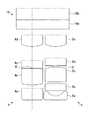
また、内視鏡1の先端部3の内部には、第1の対物光学系4及び第2の対物光学系5の前方には、カバーガラス9a,9bがそれぞれ設けられ、第1の対物光学系4及び第2の対物光学系5とCCD6との間には、カバーガラス10が設けられている。
また、CCD6とカバーガラス10との間には視野マスク11が設けられている。この視野マスク11の形状の一例を図3に示す。第1の対物光学系4及び第2の対物光学系5を通った光は、この視野マスク11により光束の通る範囲を制限され、図4に示すCCD6上の結像領域7,8内にそれぞれ結像するようになっている。
【0033】
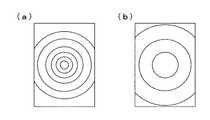
図5は、図2と同じ構成の内視鏡1の先端部3の断面図である。この先端部3において、第2の対物光学系5の光軸がCCD6の結像面に垂直のまま結像範囲中心からずらして配置されており、第1の対物光学系4の視野中心と第2の対物光学系5の視野中心とが被写界深度内においてほぼ一致するようになっている。ここで、図2のように光軸と結像範囲中心が一致している場合の視野の概念図を図6に示す。図6において、(a)は第2の対物光学系5の視野の中心を示し、(b)は第1の対物光学系4の視野の中心を示す。
また、図5のように光軸が結像範囲中心からずらして配置された場合の視野の概念図を図7に示す。図7において、(a)は第2の対物光学系5の視野の中心を示し、(b)は第1の対物光学系4の視野の中心を示す。
【0034】
次に、上記の構成からなる内視鏡装置の作用について説明する。
この内視鏡装置を用いて被写体、例えば体腔内を観察する場合、第2の対物光学系5を用いて拡大観察を行いたい体腔内の部位を見つけ出すとともに、同時にほぼ同じ部位を撮像している第1の対物光学系4によって拡大観察を行う。
【0035】
この場合、CCD6上における第1の対物光学系4の結像の大きさが、CCD6上における第2の対物光学系5の結像の大きさの2倍以上の条件を満たすことにより、例えば内視鏡装置によって体腔内を撮像する場合、内視鏡1の先端部3を体腔内に挿入する際のガイド用として、あるいは拡大観察を行いたい体腔内の部位に第1の対物光学系の視野範囲を導くためのオリエンテーション用として第2の対物光学系を用い、その第2の対物光学系の拡大観察用として第1の対物光学系を用いるのに適当な倍率となる。
【0036】
また、CCD6上における第1の対物光学系4の結像の大きさが、CCD6上における第2の対物光学系5の結像の大きさの5倍未満の条件を満たすことにより、第1の対物光学系4の被写界深度が狭くなることが回避され、第1の対物光学系4の実用上必要な被写界深度が得られることとなる。
【0037】
また、CCD6で2つの点像を識別するためには、少なくとも、点像の距離に対して、モノクロのCCD6で2画素、カラーのCCD6では3画素が必要である。一方、第1の対物光学系4及び第2の対物光学系5による結像の際、回折の影響を受けるため、光学系に収差がなくても、接近した2つの点像を別々の像として識別できる距離には限界があり、その距離は、波長λ(=0.588(μm))、第1の対物光学系の開口比Fmとすると、1.22×λ×Fmで表される。
【0038】
したがって、2つの点像を識別するために必要な画素数分の距離よりも、1.22×λ×Fmの値が大きくなると、CCD6の画素数を生かせず、被写体の細部がぼけたように見えてしまうため、モノクロのCCD6では2.2画素分、カラーのCCD6では3.3画素分の画素数が必要である。したがって、CCD6の画素ピッチP(μm)とすると、1.22×λ×Fmの値がモノクロのCCD6で2.2×P以下、カラーのCCD6で3.3×P以下となることにより、CCD6の画素数を生かして被写体の細部が鮮明に映し出されることとなる。
【0039】
しかしながら、Fmを小さくしすぎてしまうと、第1の対物光学系4では被写界深度が非常に狭くなってしまい、観察窓と被写体までの距離が僅かでもずれると観察像がいわゆるピンボケになってしまうため、Fmをある程度大きく設定する必要がある。したがって、1.22×λ×Fmの値が、モノクロのCCD6で1×P以上、カラーのCCD6で1.5×P以上となることにより、観察像のピンボケが回避されることとなる。
【0040】
また、電子式の内視鏡装置においては、得られる像の明るさに応じて照明光を自動的に調光し、最適な像の明るさで観察が行えるようになっている。したがって、1つのCCD6上に第1の対物光学系4及び第2の対物光学系5の像がそれぞれ同時に結像する場合、第1の対物光学系4及び第2の対物光学系5の明るさをそれぞれ1/Fm2,1/Fo2とし、Fm2/Fo2<2、すなわち第2の対物光学系5の明るさを第1の対物光学系4の明るさの2倍以内に設定することにより、2つの画像に対して同時に最適な明るさが得られるとともに、ハレーションが回避されることとなる。
【0041】
しかしながら、例えば内視鏡装置によって体腔内を撮像する場合において、内視鏡装置の先端部3を体腔内の観察したい部位に導く際は、第2の対物光学系5の画像を見ながら行うことになるため、このとき、ある程度遠方まで明るく見えないと第2の体物光学系5がオリエンテーションとしての役割を果たせない。したがって、1<Fm2/Fo2となり、すなわち第2の対物光学系5は第1の対物光学系4よりも明るく設定されることとなる。
【0042】
また、図5に示すように、第1の対物光学系4及び第2の対物光学系5が平行に並んで配置され、第2の対物光学系5の光軸を結像範囲中心からずらして配置して、第1の対物光学系4の視野中心を被写界深度内において第2の対物光学系5の視野中心とほぼ一致させることにより、第1の対物光学系4及び第2の対物光学系5の組立作業を行う際、第1の対物光学系4及び第2の対物光学系5を保持する枠の構造を複雑にすることがないため、容易に組立てられる。
また、第2の対物光学系5の光軸のずらし量に応じて視野方向が傾くため、拡大観察を行いたい部位に第1の対物光学系4の画面を導く作業を容易な操作で行えるようになる。
【0043】
また、CCD6に近い位置に2つの切り通し部を有する視野マスク11を配置することにより、2つの対物光学系の視野周辺から視野外にかけての領域からCCD6に入射する光線が、それぞれ視野マスクで制限されるので、撮像素子の受光面上で互いの像に対してゴーストフレアなどの悪影響を与えることを防ぐことができる。
【0044】
上記の構成によれば、例えば内視鏡装置によって体腔内を撮像する場合、内視鏡の先端を体腔内に挿入する際のガイド用として、あるいは拡大観察を行いたい体腔内の部位に第1の対物光学系4の視野範囲を導くためのオリエンテーション用として第2の対物光学系5を用い、その第2の対物光学系5の拡大観察用として第1の対物光学系4を用いるのに適当な倍率となるとともに、第1の対物光学系4の被写界深度が狭くなることが回避され、第1の対物光学系4の実用上必要な被写界深度が得られることとなるので、拡大観察と通常観察とを同時に行うことができる。
【0045】
また、CCD6の画素ピッチP(μm)とすると、1.22×λ×Fmの値がモノクロのCCD6で1×P以上2.2×P以下、カラーのCCD6で1.5×P以上3.3×P以下となることにより、CCD6の画素数を生かして被写体の細部が鮮明に映し出されることとなるので、拡大観察と通常観察とを同時に行うことができる。
【0046】
また、第2の対物光学系5の明るさを第1の対物光学系4より明るく設定し、かつその明るさを2倍以内に設定することにより、2つの画像に対して同時に最適な明るさが得られるとともに、ハレーションが回避されることとなるので、高倍率と低倍率との明るさのバランスが取れていて、拡大観察と通常観察とを同時に行うことができる。
【0047】
第1の対物光学系4及び第2の対物光学系5の組立作業を行う際、第1の対物光学系4及び第2の対物光学系5を保持する枠の構造を複雑にすることがないため、容易に組立てられるので、煩雑な操作をすることなく拡大観察あるいは特殊光観察と通常観察とを同時に行うことができる。
また、第1の対物光学系4及び第2の対物光学系5の光軸のずらし量に応じて視野方向が傾くため、拡大観察を行いたい部位に第1の対物光学系4の画面を導く作業を容易な操作で行えるようになるので、2つの画像の視野中心のずれがなく拡大観察と通常観察とを同時に行うことができる。
【0048】
なお、上記実施の形態においては、第1の対物光学系4の内部あるいは後方に、赤外光観察用の可視光カットフィルタ、狭帯域光観察用のバンドパスフィルタ、もしくは蛍光観察用の励起光カットフィルタが設けられてもよい。これにより、従来の体腔内の観察に用いられる内視鏡装置のように、観察中に一旦特殊光観察用の内視鏡装置を体腔内から取り出して、通常光観察用として別の内視鏡装置を再度挿入し、あるいは光源の切替えを行うといった煩雑な操作を行うことなく、赤外光、狭帯域光、あるいは蛍光による特殊光観察により病変部を探しながら、通常光観察で同時に位置確認や処置を行い、あるいは特殊光観察による観察像と通常の白色光による像と対比させて観察することが可能となる。
【0049】
特に、第1の対物光学系4の後方に可視光の一部を遮断するフィルタを設けることで、例えばセンチネルリンパ管の観察を行う場合、組織にインドシアニングリーン(ICG)の注入を行い、第2の対物光学系5の通常光観察により観察を行いたい部位まで視野範囲を導き、第1の対物光学系4の近接拡大画面による赤外光観察にて、ICGが蓄積されたセンチネルリンパ節の同定を行い、第2の対物光学系5の通常光観察画面を見ながら必要な処置を行うといった操作を容易に行えるようになる。さらに、センチネルリンパ節を切除した後に切除部位周辺組織の蛍光観察を行い、病変組織の取り残しの有無を確認することが可能である。
【0050】
また、視野マスク11を、半導体製造プロセスで使用されるエッチング手法におけるブラックシリコン化処理を応用して製作してもよい。それによって、視野マスク11の表面の反射率をほぼゼロ%にすることが可能である。また、視野マスク11の表面に入射した光は全て吸収されるので、例えば撮像素子の受光面で反射して視野マスク11へ入射した光が、視野マスク11で反射して再び受光面に入射し、ゴーストフレアとなるのを防ぐことができる。
【0051】
【実施例】
本発明の内視鏡装置について、内視鏡1の先端部3に設けられた第1の対物光学系4及び第2の対物光学系5のデータ及び断面図を実施例として示す。以下の実施例における断面図については、第1の対物光学系4、第2の対物光学系5、及びカバーガラス10の構成のみ示すものとする。ただし、第1の対物光学系4の開口比Fm、第2の対物光学系5の開口比Fo、最大像高IH、各レンズ面の曲率半径R、各レンズの肉厚及びレンズ間隔D、d線での屈折率Nd、アッベ数Vd、波長λ=0.588(μm)とする。
【0052】
[実施例1]
図8は、本実施例の第1の対物光学系4、第2の対物光学系5及びカバーガラス10の構成を示す概略断面図である。
第1の対物光学系4は、3つのレンズ4a,4b,4cを備えている。また、第2の対物光学系5は、4つのレンズ5a,5b,5c,5dを備えている。さらに、カバーガラス10は、3つのカバーガラス10a,10b,10cを備えている。なお、カバーガラス10cの後方には、図示しないモノクロのCCDが設けられている。また、レンズ4bの後端には明るさ絞り4’が設けられ、レンズ5dの先端には明るさ絞り5’が設けられている。
このとき、表1に示すように、第1の対物光学系4の開口比Fm、第2の対物光学系5の開口比Fo、最大像高IH、各レンズ面の曲率半径R、各レンズの肉厚及びレンズ間隔D、d線での屈折率Nd、アッベ数Vdを設定すると、第1の対物光学系4の結像の大きさが、第2の対物光学系5の結像の大きさの2倍以上5倍未満となる。また、CCDがモノクロの場合、CCDの画素ピッチP(μm)、波長λ、第1の対物光学系4の開口比Fmとすると、
1×P<1.22×λ×Fm<2.2×P
となり、第1の対物光学系4の開口比Fm、第2の対物光学系5の開口比Foとすると、
1<Fm2/Fo2<2
となる。
【0053】
【表1】
【表2】
[実施例2]
図9は、本実施例の第1の対物光学系4、第2の対物光学系5及びカバーガラス10の構成を示す概略断面図である。
第1の対物光学系4は、4つのレンズ4a,4b,4c,4dを備えている。また、第2の対物光学系5は、5つのレンズ5a,5b,5c,5d,5eを備えている。さらに、カバーガラス10は、2つのカバーガラス10a,10bを備えている。なお、カバーガラス10bの後方には、図示しないカラーのCCDが設けられている。また、レンズ4bの後端には明るさ絞り4’が設けられ、レンズ5dの先端には明るさ絞り5’が設けられている。
このとき、表2に示すように、第1の対物光学系4の開口比Fm、第2の対物光学系5の開口比Fo、最大像高IH、各レンズ面の曲率半径R、各レンズの肉厚及びレンズ間隔D、d線での屈折率Nd、アッベ数Vdを設定すると、第1の対物光学系4の結像の大きさが、第2の対物光学系5の結像の大きさの2倍以上5倍未満となる。また、CCDがカラーの場合、CCDの画素ピッチP(μm)、波長λ、第1の対物光学系4の開口比Fmとすると、
1.5×P<1.22×λ×Fm<3.3×P
となり、第1の対物光学系4の開口比Fm、第2の対物光学系5の開口比Foとすると、
1<Fm2/Fo2<2
となる。
【0056】
【表3】
【表4】
[実施例3]
図10は、本実施例の第1の対物光学系4、第2の対物光学系5及びカバーガラス10の構成を示す概略断面図である。
第1の対物光学系4は、3つのレンズ4a,4b,4cを備えている。また、第2の対物光学系5は、3つのレンズ5a,5b,5cを備えている。さらに、カバーガラス10は、3つのカバーガラス10a,10b,10cを備えている。なお、カバーガラス10cの後方には、図示しないモノクロのCCDが設けられている。また、レンズ4aの後端には明るさ絞り4’が設けられ、レンズ5bの後端には明るさ絞り5’が設けられている。
このとき、表3に示すように、第1の対物光学系4の開口比Fm、第2の対物光学系5の開口比Fo、最大像高IH、各レンズ面の曲率半径R、各レンズの肉厚及びレンズ間隔D、d線での屈折率Nd、アッベ数Vdを設定すると、第1の対物光学系4の結像の大きさが、第2の対物光学系5の結像の大きさの2倍以上5倍未満となる。また、CCDがモノクロの場合、CCDの画素ピッチP(μm)、波長λ、第1の対物光学系4の開口比Fmとすると、
1×P<1.22×λ×Fm<2.2×P
となり、第1の対物光学系4の開口比Fm、第2の対物光学系5の開口比Foとすると、
1<Fm2/Fo2<2
となる。
なお、第2の対物光学系5の光軸を結像範囲中心からずらしており、これにより、第1の対物光学系4と第2の対物光学系5との視野中心を一致させている。このときの第1の対物光学系4及び第2の対物光学系5の光路図を図11に示す。
【0059】
【表5】
【表6】
[実施例4]
図12は、本実施例の第1の対物光学系4、第2の対物光学系5及びカバーガラス10の構成を示す概略断面図である。
第1の対物光学系4は、3つのレンズ4a,4b,4cを備えている。また、第2の対物光学系5は、4つのレンズ5a,5b,5c,5dを備えている。さらに、カバーガラス10は、5つのカバーガラス10a〜10eを備えている。なお、カバーガラス10cの後方には、図示しないモノクロのCCDが設けられている。また、第1の対物光学系4の後方のカバーガラス10d,10eは、赤外観察のための可視光カットフィルタの機能を有している。
カバーガラス10b,10c間及びカバーガラス10e,10c間には、視野マスク11が設けられている。また、レンズ4aの後端には明るさ絞り4’が設けられ、レンズ5bの後端には明るさ絞り5’が設けられている。
赤外観察の詳細については後述する。
このとき、表4に示すように、第1の対物光学系4の開口比Fm、第2の対物光学系5の開口比Fo、最大像高IH、各レンズ面の曲率半径R、各レンズの肉厚及びレンズ間隔D、d線での屈折率Nd、アッベ数Vdを設定すると、第1の対物光学系4の結像の大きさが、第2の対物光学系5の結像の大きさの2倍以上5倍未満となる。また、CCD6がモノクロの場合、CCD6の画素ピッチP(μm)、波長λ、第1の対物光学系4の開口比Fmとすると、
1×P<1.22×λ×Fm<2.2×P
となり、第1の対物光学系4の開口比Fm、第2の対物光学系5の開口比Foとすると、
1<Fm2/Fo2<2
となる。
【0062】
【表7】
【表8】
[実施例5]
図13は、本実施例の第1の対物光学系4、第2の対物光学系5及びカバーガラス10の構成を示す概略断面図である。
第1の対物光学系4は、7つのレンズ4a〜4gを備えている。また、第2の対物光学系5は、6つのレンズ5a〜5fを備えている。さらに、カバーガラス10は、2つのカバーガラス10a,10bを備えている。なお、カバーガラス10bの後方には、図示しないカラーのCCDが設けられている。また、レンズ4dは、蛍光観察のための励起光カットフィルタの機能を有している。
カバーガラス10a,10b間には、2つの切り通し部を有する視野マスク11が配置されている。また、レンズ4dの後端には明るさ絞り4’が設けられ、レンズ5cの後端には明るさ絞り5’が設けられている。
このとき、表5に示すように、第1の対物光学系4の開口比Fm、第2の対物光学系5の開口比Fo、最大像高IH、各レンズ面の曲率半径R、各レンズの肉厚及びレンズ間隔D、d線での屈折率Nd、アッベ数Vdを設定すると、第1の対物光学系4の結像の大きさが、第2の対物光学系5の結像の大きさの2倍以上5倍未満となる。また、CCD6がカラーの場合、CCD6の画素ピッチP(μm)、波長λ、第1の対物光学系4の開口比Fmとすると、
1.5×P<1.22×λ×Fm<3.3×P
となり、第1の対物光学系4の開口比Fm、第2の対物光学系5の開口比Foとすると、
1<Fm2/Fo2<2
となる。
【0065】
【表9】
【表10】
ここで、赤外観察について以下に説明する。
赤外観察では、照明光として680nmから1100nmの赤外波長範囲から任意の狭い波長範囲の光を選び、これを生体組織へ照射することによって、生体組織の粘膜下層からの情報を取得することができる。生体組織の粘膜下層付近には比較的太い血管やリンパ管が存在する。そこで、近赤外光に吸収ピークをもつインドシアニングリーン(ICG)などを造影剤として上記血管やリンパ管に注入し、上記血管やリンパ管に陰影をつけることでこれらを明瞭に観察することができる。
【0068】
例えば、センチネルリンパ節の同定および切除は、赤外観察画像を観察しながら内視鏡的に行うことができる。すでに述べたように、センチネルリンパ節は、癌などの病変からのリンパ液が流れ込んで、最初の微小転移が生じる場所であり、更に体内の別の場所への転移はセンチネルリンパ節を基点として起こるといわれている。つまり、センチネルリンパ節を調べれば、その症例のリンパ節転移状況を把握できる。また、早期癌の場合には、内視鏡下で病変部付近のセンチネルリンパ節を同定し、病変部とともにセンチネルリンパ節まで含めて切除することで、体内の別の場所への転移を防ぐことができる。
【0069】
センチネルリンパ節の切除では、その付近を走行する血管を誤って傷つけて出血させないように、リンパ管と血管が明瞭に区別できるような赤外観察画像を提供する必要がある。本実施例の変形例として、ICGの吸収ピーク波長である805nm付近の近赤外光と、ICGの吸収率の低い930nm付近の近赤外光と、静脈血に含まれる酸化ヘモグロビンの吸収波長である550nm付近の可視光とを照明光として病変部付近の生体組織に照射し、生体組織からの反射光を撮像してリンパ管内のICGと血管の分布をそれぞれ擬似的に着色して表示するようにしたものを以下に示す。
【0070】
図14に酸化ヘモグロビン(HbO2)の吸光特性を示した。これによると、酸化ヘモグロビンは550nm付近の可視光を大きく吸収するのに比べて、805nmおよび930nm付近の光の吸収は少なく、しかも805nmおよび930nm付近ではほぼ同じような吸光特性を示すことがわかる。一方、ICGは体内において、805nm付近の近赤外光を大きく吸収するのに比べて、550nmおよび930nm付近の光をほとんど吸収しない。そこで、画像処理する時点で上記3つの波長の光に対してそれぞれ青色、緑色、赤色を擬似的に割り当て、撮像素子の受光強度に応じて混色して画像表示することによって、リンパ管と血管を異なる色調として明瞭に区別できる赤外観察画像を提供することができる。
【0071】
この場合、光源装置は内視鏡の照明ユニットを通して図15に示した波長範囲の光を被写体に向けて順番に繰り返し照明する。図15の分光強度曲線Aは可視領域に属する550nmを中心として半値幅で30nmの波長範囲の照明光である。また、分光強度曲線Bは近赤外領域に属する790nmから820nmの波長範囲の照明光である。また、分光強度曲線Cは近赤外領域に属する920nmから950nmの波長範囲の照明光である。
【0072】
光源装置の光学系の構成を図16に示した。上記光学系は、ランプ100の開口窓の像を縮小して投影するレンズ系101aと、前記ランプの光束を内視鏡のライトガイド入射端面102に集光するレンズ系101bから構成されている。ランプ100から上記レンズ系を通って内視鏡のライトガイド入射端面102に至るまでの光路中に設置されたターレット103と回転ディスク104がそれぞれ配置されている。
【0073】
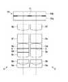
ターレット103および回転ディスク104には数種類の光学フィルタが取付けられており、ターレット103および回転ディスク104が光源光学系の光軸に対して垂直な面にそって移動し、かつ光軸に平行な回転軸を中心にして回転することによって、光源光学系の光束中に光学フィルタを挿入するようになっている。赤外光観察時にはターレット103が回転して図17の光学フィルタ111が光路中に挿入される。また、回転ディスク104が移動して上記回転ディスクの外周部が光路中に挿入される。そして、上記回転ディスクが回転して、外周部に取付けられた図17の光学フィルタ115、116、117が一定の周期で繰り返し挿入される。
【0074】
図17の光学フィルタ111は、535nmから565nmと790nmから950nmの透過範囲を持つフィルタである。また、図18の光学フィルタ115は、385nmから495nmの透過範囲を持ち、かつ920nm以上の光を透過するフィルタであり、光学フィルタ115が光路中に挿入されているときには、920nmから950nmの波長範囲の赤外領域の照明光が生成される。
【0075】
図18の光学フィルタ116は、500nmから575nmの透過範囲を持つフィルタであり、光学フィルタ116が光路中に挿入されているときには、535nmから565nmの波長範囲の可視領域の照明光が生成される。
図18の光学フィルタ117は、585nmから655nmの透過範囲を持ち、かつ745nmから820nmの透過範囲をもつフィルタであり、光学フィルタ117が光路中に挿入されているときには、790nmから820nmの波長範囲の赤外領域の照明光が生成される。
また、内視鏡の高倍側の対物光学系には、図19の光学フィルタ130が配置されている。光学フィルタ130は500nmより長波長側の光を透過する特性をもつフィルタである。したがって、生体組織を反射した上記3種類の波長範囲の照明光は、対物光学系を通して撮像素子の撮像面に到達する。
【0076】
上記の内視鏡は、内視鏡下で病変部とその付近のセンチネルリンパ節を切除した後にそれらが確実に除去できているかどうかを確認するために、切除された部分に励起光を照射して生体組織の自家蛍光を観察することもできる。正常な生体組織が発する蛍光の分光強度分布と癌などの病変部が発する蛍光の分光強度分布を比較すると、上記病変部の生体組織が発する蛍光の強度が相対的に低下することが知られている。
【0077】
そこで、上記のような蛍光強度の差を利用して生体組織から病変部分を分離して表示するようにビデオプロセッサで画像処理した蛍光画像を観察することで病変の取り残しの有無を確認することができる。この場合、光源装置のターレット103が回転して図17の光学フィルタ112が光路中に挿入される。光学フィルタ112は440nmより短波長側の光を透過する特性をもつフィルタであり、回転ディスク104に取付けられた光学フィルタ115が光路中に挿入されたときに、385nmから440nmの波長範囲の励起光が生成される。上記励起光によって、生体組織は510nm付近に強度ピークを持つ蛍光を発するので、内視鏡の高倍側の対物光学系は、励起光をカットして生体組織の自家蛍光のみを撮像素子の撮像面に到達させることができる。
【0078】
一方、内視鏡の低倍側の対物光学系には、図19の光学フィルタ131が配置されている。図19の光学フィルタ131は、455nmから680nmの波長範囲の光を透過する特性をもつフィルタである。このため、低倍側の対物光学系を通して励起光が撮像素子の撮像面に到達することはない。通常観察時には、光源装置のターレット103が回転して図17の光学フィルタ113が光路中に挿入される。
【0079】
図17の光学フィルタ113は、390nmから695nmの透過範囲をもつバンドパスフィルタであり、図18の光学フィルタ115、116、117と組み合わされて、385nmから495nmの青色光、500nmから575nmの緑色光、585nmから655nmの赤色光がそれぞれ生成される。したがって、生体組織を反射した青色光は、対物光学系を通して455nmから495nmの波長成分の光のみが撮像素子の撮像面に到達する。
なお、光学フィルタの透過特性を表す場合、透過率T=50%となる波長λ1とλ2を使って、λ1からλ2の透過範囲をもつバンドパスフィルタとかλ1以上の光を透過するフィルタとかλ1からλ2の光をカットするフィルタのように表した。
【0080】
【発明の効果】
以上説明したこの発明の内視鏡装置においては、以下の効果を奏する。
請求項1に係る発明によれば、例えば内視鏡装置によって体腔内を撮像する場合、内視鏡の先端を体腔内に挿入する際のガイド用として、あるいは拡大観察を行いたい体腔内の部位に第1の対物光学系の視野範囲を導くためのオリエンテーション用として第2の対物光学系を用い、その第2の対物光学系の拡大観察用として第1の対物光学系を用いるのに適当な倍率となるとともに、第1の対物光学系の被写界深度が狭くなることが回避され、第1の対物光学系の実用上必要な被写界深度が得られることとなるので、拡大観察と通常観察とを同時に行うことができる。
【0081】
請求項2に係る発明によれば、固体撮像素子の画素ピッチP(μm)とすると、1.22×λ×Fmの値がモノクロの固体撮像素子で1×P以上2.2×P以下となることにより、固体撮像素子の画素数を生かして被写体の細部が鮮明に映し出されることとなるので、拡大観察と通常観察とを同時に行うことができる。
【0082】
請求項3に係る発明によれば、固体撮像素子の画素ピッチP(μm)とすると、1.22×λ×Fmの値がカラーの固体撮像素子で1.5×P以上3.3×P以下となることにより、固体撮像素子の画素数を生かして被写体の細部が鮮明に映し出されることとなるので、拡大観察と通常観察とを同時に行うことができる。
【0083】
請求項4に係る発明によれば、第2の対物光学系の明るさを第1の対物光学系より明るく設定され、かつその明るさを2倍以内に設定することにより、2つの画像に対して同時に最適な明るさが得られるとともに、ハレーションが回避されることとなるので、高倍率と低倍率との明るさのバランスが取れていて、拡大観察と通常観察とを同時に行うことができる。
【0084】
請求項5に係る発明によれば、第1及び第2の対物光学系の組立作業を行う際、第1及び第2の対物光学系を保持する枠の構造を複雑にすることがないため、容易に組立てられるので、煩雑な操作をすることなく拡大観察あるいは特殊光観察と通常観察とを同時に行うことができる。
また、第1及び第2の対物光学系の光軸のずらし量に応じて視野方向が傾くため、拡大観察を行いたい部位に第1の対物光学系の画面を導く作業を容易な操作で行えるようになるので、2つの画像の視野中心のずれがなく拡大観察と通常観察とを同時に行うことができる。
【0085】
請求項6に係る発明によれば、従来の体腔内の観察に用いられる内視鏡装置のように、観察中に一旦特殊光観察用の内視鏡装置を体腔内から取り出して、通常光観察用として別の内視鏡装置を再度挿入し、あるいは光源の切替えを行うといった煩雑な操作を行うことなく、赤外光、狭帯域光、あるいは蛍光による特殊光観察により病変部を探しながら、通常光観察で同時に位置確認や処置を行い、あるいは特殊光観察による観察像と通常の白色光による像と対比させて観察することが可能となるので、煩雑な操作をすることなく特殊光観察と通常観察とを同時に行うことができる。
【0086】
請求項7に係る発明によれば、2つの対物光学系の視野周辺から視野外にかけての領域から固体撮像素子に入射する光線が、それぞれ視野マスクで制限されるので、撮像素子の受光面上で互いの像に対してゴーストフレアなどの悪影響を与えることを防いで拡大観察あるいは特殊光観察と通常観察とを同時に行うことができる。
【図面の簡単な説明】
【図1】 本発明における実施の形態に係る内視鏡装置の部分側面図である。
【図2】 本発明における実施の形態に係る内視鏡装置の先端部の部分断面図である。
【図3】 本発明における実施の形態に係る視野マスクの一例を示す図である。
【図4】 本発明における実施の形態に係る固体撮像素子とその結像領域を示す図である。
【図5】 本発明における実施の形態に係る内視鏡装置の先端部の部分断面図である。
【図6】 本発明における実施の形態に係る内視鏡装置によって光軸と結像範囲中心とを一致させて撮像された視野範囲の概念図である。
【図7】 本発明における実施の形態に係る内視鏡装置によって光軸を結像中心からずらして撮像された視野範囲の概念図である。
【図8】 本発明における実施例1に係る内視鏡装置に備えられた対物光学系の概略断面図である。
【図9】 本発明における実施例2に係る内視鏡装置に備えられた対物光学系の概略断面図である。
【図10】 本発明における実施例3に係る内視鏡装置に備えられた対物光学系の概略断面図である。
【図11】 本発明における実施例3に係る内視鏡装置に備えられた対物光学系の光路図である。
【図12】 本発明における実施例4に係る内視鏡装置に備えられた対物光学系の概略断面図である。
【図13】 本発明における実施例5に係る内視鏡装置に備えられた対物光学系の概略断面図である。
【図14】 本発明における実施例4に係る赤外観察における酸化ヘモグロビンの吸光特性を示す図である。
【図15】 本発明における実施例4に係る赤外観察における分光強度曲線を示す図である。
【図16】 本発明における実施例4に係る赤外観察における光源装置の光学系の構成を示す図である。
【図17】 本発明における実施例4に係る赤外観察における分光強度曲線を示す図である。
【図18】 本発明における実施例4に係る赤外観察における分光強度曲線を示す図である。
【図19】 本発明における実施例4に係る赤外観察における分光強度曲線を示す図である。
【符号の説明】
1 内視鏡
2 挿入部
3 先端部
4 第1の対物光学系
5 第2の対物光学系
6 CCD(固体撮像素子)[0001]
BACKGROUND OF THE INVENTION
The present invention includes an endoscope apparatus, in particular, two objective optical systems and one solid-state image sensor, and an object image obtained through each objective optical system is connected to different portions on the solid-state image sensor. The present invention relates to an endoscope apparatus configured to form an image.
[0002]
[Prior art]
In recent years, in order to perform precise diagnosis of lesions and the like with an endoscope, it has been required to be able to perform magnified observation in addition to normal observation. In order to satisfy such a requirement, an endoscope apparatus equipped with a zoom mechanism (see, for example, Patent Document 1) or two objective optical systems having different magnifications are arranged at the tip, and an image is formed by each objective optical system. An endoscope apparatus has been proposed in which the formed image is formed on a solid-state imaging device corresponding to each objective optical system, and two images of enlarged observation and normal observation can be observed simultaneously (for example, see Patent Document 2). ).
[0003]
In these technologies, in the case of an endoscope apparatus equipped with a zoom mechanism, the structure is complicated by the necessity of a movable part, the distal end hard part becomes longer and the insertion part diameter becomes larger, which increases the manufacturing cost. To do. Further, in the case of an endoscope apparatus provided with two solid-state image sensors, the space occupied by the solid-state image sensor increases, so that the manufacturing cost increases as in the case of an endoscope apparatus provided with a zoom mechanism. Therefore, as an endoscope apparatus that further simplifies the structure or reduces the manufacturing space by reducing the space occupied by the solid-state imaging device, the distal end portion includes two objective optical systems having different magnifications and one solid-state imaging device, There has been proposed an endoscope apparatus capable of simultaneously observing images having different magnifications by forming images formed by the respective objective optical systems in different regions on one solid-state imaging device (for example, patents). Reference 3).
[0004]
For example, when observing a body cavity with respect to two objective optical systems having different magnifications provided at the distal end of the endoscope apparatus, the first objective optical system having a high magnification places the distal end of the endoscope apparatus into the body cavity. It has a magnification that is necessary for inserting and performing magnified observation inside the body cavity. On the other hand, the second objective optical system having a low magnification is used as a guide when inserting the distal end of the endoscope apparatus into the body cavity or a field of view range of the first objective optical system at a site where magnified observation in the body cavity is desired. It has a wide viewing angle so that it can serve as an orientation for guiding.
In addition, the depth of field of the first objective optical system having a high magnification is the second depth having a low magnification so that the object can be focused by the distance between the tip of the observation window and the observation object without losing sight of the object. At least a part of the depth of field of the objective optical system overlaps.
[0005]
Also, in recent medical fields, for example, in early cancer screening, not only observation under so-called normal visible light, that is, white light, but also observation of the difference in autofluorescence between normal tissue and cancer tissue in order to improve the detection rate. Method, Indocyanine Green (ICG) is injected as a contrast agent and observed with infrared light in the absorption band of ICG, or white light cannot be obtained by irradiating only light in a specific wavelength region Observation using special light, such as a method of performing observation and diagnosis from image information, is performed by an endoscope apparatus.
[0006]
A specific example of a method of performing observation with infrared light using this ICG is observation of sentinel lymph nodes. The sentinel lymph node is the lymph node that first receives lymph flow from the tumor, where the first micrometastasis is said to occur. In other words, if the sentinel lymph node is examined, the lymph node metastasis status of the case can be grasped. Therefore, it can be said that it is medically important to identify the sentinel lymph node using an endoscope apparatus.
[0007]
[Patent Document 1]
JP-A-11-316339 (pages 12-13, FIG. 1)
[Patent Document 2]
JP-A-1-197716 (page 2-3, FIG. 1)
[Patent Document 3]
Japanese Patent Laid-Open No. 9-12068 (page 2-3, FIG. 1)
[0008]
[Problems to be solved by the invention]
By the way, in the conventional endoscope apparatus, the first objective optical system having a high magnification is used for magnifying observation in a body cavity or the like, and the depth of field becomes shallower as the magnification becomes higher. When the distance to the subject is slightly shifted, there is a problem that the observation image becomes so-called out of focus. Therefore, it is necessary to make the depth of field as wide as possible while securing the necessary magnification, and for that purpose, it is necessary to increase the aperture ratio Fm of the first objective optical system as much as possible. However, if the aperture ratio Fm of the first objective optical system is increased too much, the resolving power deteriorates due to the influence of light diffraction.
[0009]
In addition, the second objective optical system having a low magnification is used for guiding when the endoscope tip is inserted into a body cavity, for orientation for guiding the visual field range of the first objective optical system having a high magnification, etc. It is bright enough to observe the inside of the body cavity so as to assume a role.
However, if the difference in brightness between the two objective optical systems is large, for example, when the optimum brightness adjustment is performed on the image by the first objective optical system, the observation image of the second objective optical system halates. There was a problem that it would wake up or become difficult to observe because it was too dark.
[0010]
Further, in such an endoscope apparatus provided with two objective optical systems having different magnifications and one solid-state imaging device at the tip, the two objective optical systems are arranged in parallel, so that the optical axes are parallel. In this case, there is a problem that a slight shift occurs in the center of the field of view of each of the two objective optical systems.
That is, if the tip of the first objective optical system is brought close to the subject for magnified observation of the subject, the deviation of the center of the field of view between the two objective optical systems is also enlarged. Therefore, even if the part to be magnified and observed by the first objective optical system is guided to the center of the visual field while viewing the screen projected by the second objective optical system, the part is actually magnified by the first objective optical system. Does not match the visible part.
Therefore, in order to solve the above problems, when the optical axis of the objective lens provided in the objective optical system is tilted to align the center of the field of view, the structure of the frame that holds the objective lens becomes complicated. This increases the difficulty of assembling work and increases the manufacturing cost.
[0011]
In addition, in an endoscope apparatus for special light observation, when performing observation while switching to white light for a lesioned part or a part to be treated that has been discovered by special light observation, the endoscope apparatus is once in the body. And an operation for switching the light source and the camera control unit from those for special light observation to those for normal light observation are necessary. In addition, even when special light observation and magnified observation are combined, observation is performed by switching to white light for position confirmation and treatment for lesions found by magnifying observation with special light and parts to be treated. When doing this, first remove the scope from the body, reinsert the normal observation scope and search for the observation site again, or switch the light source and camera control unit to those for normal light observation, and observe the scope tip. An operation for taking a wider field of view away from the site is required. With this method, a large change in magnification cannot be expected.
[0012]
In view of the above problems, the present invention balances the brightness between the high magnification and the low magnification, and there is no deviation of the center of the field of view between the two images. An object of the present invention is to provide an endoscope apparatus capable of performing special light observation and normal observation at the same time.
[0013]
[Means for Solving the Problems]
The present invention employs the following means in order to solve the above problems.
The invention according to claim 1 includes two objective optical systems including a first objective optical system and a second objective optical system having a lower magnification than the first objective optical system, and one solid-state imaging device. The object in front of the first objective optical system or the second objective optical system is connected to different regions of the solid-state imaging device via the first objective optical system or the second objective optical system. An endoscope apparatus in which the visual field range of the first objective optical system is included in or overlaps the visual field range of the second objective optical system, the solid-state imaging device The size of the image of the first objective optical system above satisfies the condition that the size of the image of the second objective optical system on the solid-state imaging device is not less than 2 times and less than 5 times. And
[0014]
According to the present invention, the size of the image of the first objective optical system on the solid-state image sensor satisfies the condition that the image size of the second objective optical system on the solid-state image sensor is twice or more. Thus, for example, when the inside of a body cavity is imaged by an endoscope apparatus, the first objective optical system is used as a guide when inserting the distal end of the endoscope into the body cavity or at a site in the body cavity where enlargement observation is desired. The magnification is appropriate for using the second objective optical system for orientation for deriving the visual field range and for using the first objective optical system for magnification observation of the second objective optical system.
In addition, the first imaging optical system on the solid-state imaging device satisfies the condition that the imaging size of the first objective optical system is less than 5 times the imaging size of the second objective optical system on the solid-state imaging device. It is avoided that the depth of field of the first objective optical system becomes narrow, and the depth of field necessary for practical use of the first objective optical system is obtained.
[0015]
According to a second aspect of the present invention, in the endoscope apparatus according to the first aspect, when the solid-state image sensor is monochrome, the pixel pitch P (μm), the wavelength λ (μm) of the solid-state image sensor, the first When the aperture ratio Fm of the objective optical system is satisfied, the condition of 1 × P <1.22 × λ × Fm <2.2 × P is satisfied.
[0016]
According to a third aspect of the present invention, in the endoscope apparatus according to the first aspect, when the solid-state image sensor is a color, the pixel pitch P (μm), the wavelength λ (μm) of the solid-state image sensor, the first When the aperture ratio Fm of the objective optical system is satisfied, the condition of 1.5 × P <1.22 × λ × Fm <3.3 × P is satisfied.
[0017]
In general, in order to distinguish two point images with a solid-state image sensor, at least two pixels are required for a monochrome solid-state image sensor and three pixels are required for a color solid-state image sensor with respect to the distance between the point images. On the other hand, since it is affected by diffraction when forming an image with a lens, there is a limit to the distance at which two close point images can be identified as separate images even if there is no aberration in the optical system. According to the Rayleigh resolution equation, when two point images approach each other, the limit distance that can be identified as separate images is the wavelength λ (= 0.588 (μm)), the aperture ratio Fm of the first objective optical system. Then, it is expressed by 1.22 × λ × Fm. Therefore, if the value of 1.22 × λ × Fm is larger than the distance of the number of pixels necessary to distinguish two point images, the number of pixels of the solid-state image sensor cannot be used and the details of the subject are blurred. It looks like this. Actually, in consideration of the influence of the aberration of the objective lens, etc., the number of pixels necessary to distinguish two point images is 2.2 pixels for a monochrome solid-state image sensor, and 3. It is appropriate to use 3 pixels. Therefore, according to these inventions, assuming that the pixel pitch P (μm) of the solid-state image sensor is 1.22 × λ × Fm, a monochrome solid-state image sensor is 2.2 × P or less. Therefore, the details of the subject are clearly displayed by making use of the number of pixels of the solid-state imaging device.
[0018]
However, even if these conditions are satisfied, if Fm is excessively decreased, the depth of field becomes very narrow in the first objective optical system, and the distance from the observation window to the subject is slightly small. However, if the image is shifted, the observation image becomes so-called out-of-focus, so it is necessary to set Fm to be large to some extent. Therefore, when the value of 1.22 × λ × Fm is 1 × P or more for the monochrome solid-state image sensor and 1.5 × P or more for the color solid-state image sensor, the out-of-focus image is avoided. It becomes.
[0019]
According to a fourth aspect of the present invention, in the endoscope apparatus according to the second or third aspect, assuming that the aperture ratio Fm of the first objective optical system and the aperture ratio Fo of the second objective optical system are 1 <Fm2 / Fo2 <2 is satisfied.
[0020]
In general, in an electronic endoscope apparatus, illumination light is automatically adjusted according to the brightness of an obtained image so that observation can be performed with the optimum image brightness. Therefore, when the images of the two objective optical systems are simultaneously formed on one solid-state imaging device, the brightness of the first and second objective optical systems is set to 1 / Fm, respectively.2 , 1 / Fo2 Fm2 / Fo2 <2, that is, by setting the brightness of the second objective optical system to be within twice the brightness of the first objective optical system, it is possible to obtain optimum brightness for two images at the same time, and to perform halation Will be avoided.
[0021]
However, for example, when the inside of a body cavity is imaged by an endoscope apparatus, when the tip of the endoscope apparatus is guided to a site to be observed in the body cavity, it is performed while viewing the image of the second body optical system. Therefore, at this time, the second body optical system cannot play the role of orientation unless it looks bright to some distance. Therefore, 1 <Fm2 / Fo2 That is, the second objective optical system is set brighter than the first objective optical system.
[0022]
The invention according to
[0023]
According to the present invention, the two objective optical systems are arranged in parallel, and at least one optical axis of the two objective optical systems is shifted from the center of the imaging range, so that the field of view of the first objective optical system is obtained. By making the center substantially coincide with the center of the field of view of the second objective optical system within the depth of field, the first and second objective optical systems are moved when the first and second objective optical systems are assembled. Since the structure of the holding frame is not complicated, it can be easily assembled.
In addition, since the visual field direction is tilted according to the shift amount of the optical axes of the first and second objective optical systems, the operation of guiding the screen of the first objective optical system to the site where the magnified observation is desired can be performed with an easy operation. It becomes like this.
[0024]
According to a sixth aspect of the present invention, in the endoscope apparatus according to any one of the first to fifth aspects, infrared light is provided inside or behind the first objective optical system or the second objective optical system. A visible light cut filter for observation, a band pass filter for narrow band light observation, or an excitation light cut filter for fluorescence observation is provided.
[0025]
According to the present invention, the endoscope apparatus for special light observation is once taken out from the body cavity during observation, as in the conventional endoscope apparatus used for observation in the body cavity, and is separately used for normal light observation. Simultaneously with normal light observation while searching for lesions by special light observation with infrared light, narrow band light, or fluorescence without performing complicated operations such as reinserting the endoscope device or switching the light source It is possible to perform position confirmation and treatment, or to compare the observation image by special light observation with the image by normal white light.
[0026]
The invention according to claim 7 is the endoscope apparatus according to
[0027]
According to this invention, by arranging the field mask having two cut-out portions in the vicinity of the solid-state image sensor, the light rays incident on the solid-state image sensor from the region from the periphery of the field of view of the two objective optical systems to the outside of the field of view, Since each is limited by the field mask, it is possible to prevent an adverse effect such as a ghost flare on each image on the light receiving surface of the image sensor.
[0028]
DETAILED DESCRIPTION OF THE INVENTION
Embodiments of the present invention will be described below with reference to the drawings.
FIG. 1 is a diagram showing an embodiment of the present invention, and is a diagram showing an endoscope apparatus to which the present invention is applied.
The endoscope apparatus includes an endoscope 1 having a
[0029]
FIG. 2 is a cross-sectional view along the optical axis showing the configuration of the
[0030]
The first objective
A subject imaged by the endoscope 1 is imaged on different regions of the
[0031]
The image size of the first objective
Here, when the
1 × P <1.22 × λ × Fm <2.2 × P
It is said that. If the
1.5 × P <1.22 × λ × Fm <3.3 × P
It is said that. Furthermore, when the aperture ratio Fm of the first objective
1 <Fm2 / Fo2 <2
It is said that.
[0032]
In addition,
A
[0033]
FIG. 5 is a cross-sectional view of the
FIG. 7 shows a conceptual view of the visual field when the optical axis is shifted from the center of the imaging range as shown in FIG. 7A shows the center of the field of view of the second objective
[0034]
Next, the operation of the endoscope apparatus having the above configuration will be described.
When observing a subject, for example, the inside of a body cavity using this endoscope apparatus, the second objective
[0035]
In this case, the size of the image of the first objective
[0036]
Further, the first imaging
[0037]
Further, in order to identify two point images by the
[0038]
Therefore, if the value of 1.22 × λ × Fm is larger than the distance required for identifying the two point images, the number of pixels of the
[0039]
However, if Fm is made too small, the depth of field becomes very narrow in the first objective
[0040]
Further, in an electronic endoscope apparatus, illumination light is automatically adjusted according to the brightness of an obtained image so that observation can be performed with optimum image brightness. Therefore, when the images of the first objective
[0041]
However, for example, when the inside of a body cavity is imaged by an endoscope apparatus, when the
[0042]
Further, as shown in FIG. 5, the first objective
In addition, since the visual field direction is inclined according to the shift amount of the optical axis of the second objective
[0043]
In addition, by arranging the
[0044]
According to the above configuration, for example, when imaging the inside of a body cavity by an endoscope apparatus, the first is used as a guide when inserting the distal end of the endoscope into the body cavity, or at a site in the body cavity where the enlarged observation is desired. Suitable for using the second objective
[0045]
Further, assuming that the pixel pitch P (μm) of the
[0046]
In addition, the brightness of the second objective
[0047]
When assembling the first objective
In addition, since the visual field direction is tilted according to the shift amount of the optical axes of the first objective
[0048]
In the above embodiment, a visible light cut filter for infrared light observation, a bandpass filter for narrow band light observation, or excitation light for fluorescence observation is provided inside or behind the first objective
[0049]
In particular, by providing a filter that blocks a part of visible light behind the first objective
[0050]
Further, the
[0051]
【Example】
About the endoscope apparatus of this invention, the data and sectional drawing of the 1st objective
[0052]
[Example 1]
FIG. 8 is a schematic cross-sectional view showing configurations of the first objective
The first objective
At this time, as shown in Table 1, the aperture ratio Fm of the first objective
1 × P <1.22 × λ × Fm <2.2 × P
When the aperture ratio Fm of the first objective
1 <Fm2 / Fo2 <2
It becomes.
[0053]
[Table 1]
[Table 2]
[Example 2]
FIG. 9 is a schematic cross-sectional view showing configurations of the first objective
The first objective
At this time, as shown in Table 2, the aperture ratio Fm of the first objective
1.5 × P <1.22 × λ × Fm <3.3 × P
When the aperture ratio Fm of the first objective
1 <Fm2 / Fo2 <2
It becomes.
[0056]
[Table 3]
[Table 4]
[Example 3]
FIG. 10 is a schematic cross-sectional view showing configurations of the first objective
The first objective
At this time, as shown in Table 3, the aperture ratio Fm of the first objective
1 × P <1.22 × λ × Fm <2.2 × P
When the aperture ratio Fm of the first objective
1 <Fm2 / Fo2 <2
It becomes.
Note that the optical axis of the second objective
[0059]
[Table 5]
[Table 6]
[Example 4]
FIG. 12 is a schematic cross-sectional view showing configurations of the first objective
The first objective
A
Details of the infrared observation will be described later.
At this time, as shown in Table 4, the aperture ratio Fm of the first objective
1 × P <1.22 × λ × Fm <2.2 × P
When the aperture ratio Fm of the first objective
1 <Fm2 / Fo2 <2
It becomes.
[0062]
[Table 7]
[Table 8]
[Example 5]
FIG. 13 is a schematic cross-sectional view showing configurations of the first objective
The first objective
A
At this time, as shown in Table 5, the aperture ratio Fm of the first objective
1.5 × P <1.22 × λ × Fm <3.3 × P
When the aperture ratio Fm of the first objective
1 <Fm2 / Fo2 <2
It becomes.
[0065]
[Table 9]
[Table 10]
Here, infrared observation will be described below.
In infrared observation, information from the submucosal layer of a living tissue can be acquired by selecting light in an arbitrary narrow wavelength range from an infrared wavelength range of 680 nm to 1100 nm as illumination light and irradiating it on the living tissue. it can. There are relatively thick blood vessels and lymphatic vessels near the submucosa of living tissue. Therefore, indocyanine green (ICG) having an absorption peak in near-infrared light can be injected into the blood vessels and lymph vessels as a contrast agent, and these can be clearly observed by shading the blood vessels and lymph vessels. it can.
[0068]
For example, identification and excision of sentinel lymph nodes can be performed endoscopically while observing an infrared observation image. As already mentioned, the sentinel lymph node is a place where lymph from cancer and other lesions flows and the first micrometastasis occurs, and further, the metastasis to another place in the body starts from the sentinel lymph node. It is said. In other words, if the sentinel lymph node is examined, the lymph node metastasis status of the case can be grasped. In the case of early-stage cancer, identify the sentinel lymph node near the lesion under endoscopy, and remove it to the sentinel lymph node together with the lesion to prevent metastasis to other parts of the body. Can do.
[0069]
In excision of the sentinel lymph node, it is necessary to provide an infrared observation image that can clearly distinguish the lymphatic vessel from the blood vessel so as not to injure the blood vessel running in the vicinity and cause bleeding. As a modification of the present embodiment, near infrared light near 805 nm which is the absorption peak wavelength of ICG, near infrared light near 930 nm where ICG has a low absorption rate, and absorption wavelength of oxyhemoglobin contained in venous blood A certain visible light near 550 nm is used as illumination light to irradiate the living tissue near the lesion, and the reflected light from the living tissue is imaged to display the ICG and the distribution of blood vessels in the lymph vessels in a pseudo colored manner. The followings are shown below.
[0070]
FIG. 14 shows oxygenated hemoglobin (HbO2 ). According to this, it can be seen that oxyhemoglobin absorbs less visible light near 550 nm and absorbs less light near 805 nm and 930 nm, and shows almost the same light absorption characteristics near 805 nm and 930 nm. On the other hand, ICG hardly absorbs light in the vicinity of 550 nm and 930 nm as compared to the absorption of near infrared light in the vicinity of 805 nm greatly in the body. Thus, at the time of image processing, blue, green, and red are assigned to the light of the above three wavelengths in a pseudo manner, and the mixed color is displayed according to the light receiving intensity of the image sensor, thereby displaying lymphatic vessels and blood vessels. An infrared observation image that can be clearly distinguished as different color tones can be provided.
[0071]
In this case, the light source device sequentially and repeatedly illuminates light in the wavelength range shown in FIG. 15 toward the subject through the illumination unit of the endoscope. The spectral intensity curve A in FIG. 15 is illumination light having a half-value width of 30 nm centered on 550 nm belonging to the visible region. The spectral intensity curve B is illumination light having a wavelength range of 790 nm to 820 nm belonging to the near infrared region. The spectral intensity curve C is illumination light having a wavelength range of 920 nm to 950 nm belonging to the near infrared region.
[0072]
The configuration of the optical system of the light source device is shown in FIG. The optical system includes a lens system 101a that projects a reduced image of the aperture window of the
[0073]
Several types of optical filters are attached to the turret 103 and the rotating disk 104, and the turret 103 and the rotating disk 104 move along a plane perpendicular to the optical axis of the light source optical system and rotate parallel to the optical axis. By rotating around the axis, an optical filter is inserted into the light beam of the light source optical system. At the time of infrared light observation, the turret 103 rotates and the
[0074]
The
[0075]
The
The
Further, the
[0076]
The above-mentioned endoscope irradiates the excised part with excitation light in order to confirm whether or not the lesioned part and the sentinel lymph node in the vicinity have been removed under the endoscope. It is also possible to observe autofluorescence of living tissue. Comparing the spectral intensity distribution of fluorescence emitted by normal living tissue with the spectral intensity distribution of fluorescence emitted by lesions such as cancer, it is known that the intensity of fluorescence emitted by living tissues of the above lesions is relatively reduced. Yes.
[0077]
Therefore, it is possible to confirm the presence or absence of a lesion by observing a fluorescent image image-processed by a video processor so as to separate and display a lesion from a living tissue using the difference in fluorescence intensity as described above. it can. In this case, the turret 103 of the light source device rotates and the
[0078]
On the other hand, the
[0079]
The
When expressing the transmission characteristics of the optical filter, the wavelength λ at which the transmittance T = 50% is obtained.1 And λ2 and λ1 To λ2 Bandpass filter with a transmission range of λ1 Filters that transmit the above light or λ1 To λ2 It was expressed as a filter that cuts out light.
[0080]
【The invention's effect】
The endoscope apparatus of the present invention described above has the following effects.
According to the first aspect of the present invention, for example, when imaging the inside of a body cavity by an endoscope apparatus, it is used as a guide when inserting the distal end of the endoscope into the body cavity, or a part in the body cavity where enlargement observation is desired. Suitable for using the second objective optical system for orientation for deriving the visual field range of the first objective optical system, and for using the first objective optical system for magnification observation of the second objective optical system. In addition to magnification, it is avoided that the depth of field of the first objective optical system becomes narrow, and the depth of field necessary for practical use of the first objective optical system is obtained. Normal observation can be performed simultaneously.
[0081]
According to the second aspect of the present invention, assuming that the pixel pitch P (μm) of the solid-state imaging device is 1.22 × λ × Fm, the monochrome solid-state imaging device has a value of 1 × P or more and 2.2 × P or less. As a result, the details of the subject are clearly displayed by making use of the number of pixels of the solid-state imaging device, so that the enlarged observation and the normal observation can be performed simultaneously.
[0082]
According to the third aspect of the present invention, assuming that the pixel pitch P (μm) of the solid-state imaging device is 1.2 × X × Fm, the value of 1.22 × λ × Fm is 1.5 × P or more and 3.3 × P As a result of the following, the details of the subject are clearly displayed by making use of the number of pixels of the solid-state imaging device, so that the magnified observation and the normal observation can be performed simultaneously.
[0083]
According to the fourth aspect of the present invention, the brightness of the second objective optical system is set to be brighter than that of the first objective optical system, and the brightness is set within twice, so that two images can be obtained. Since the optimum brightness can be obtained at the same time and halation is avoided, the brightness balance between the high magnification and the low magnification is balanced, and the magnification observation and the normal observation can be performed simultaneously.
[0084]
According to the fifth aspect of the invention, when assembling the first and second objective optical systems, the structure of the frame that holds the first and second objective optical systems is not complicated. Since it is easily assembled, magnified observation or special light observation and normal observation can be performed at the same time without complicated operations.
In addition, since the visual field direction is tilted according to the shift amount of the optical axes of the first and second objective optical systems, the operation of guiding the screen of the first objective optical system to the site where the magnified observation is desired can be performed with an easy operation. As a result, there is no shift in the center of the field of view between the two images, and magnified observation and normal observation can be performed simultaneously.
[0085]
According to the invention of
[0086]
According to the seventh aspect of the present invention, the light rays incident on the solid-state image sensor from the region from the periphery of the field of view of the two objective optical systems to the outside of the field of view are limited by the field mask respectively. It is possible to perform magnified observation or special light observation and normal observation at the same time while preventing adverse effects such as ghost flare on each other's images.
[Brief description of the drawings]
FIG. 1 is a partial side view of an endoscope apparatus according to an embodiment of the present invention.
FIG. 2 is a partial cross-sectional view of the distal end portion of the endoscope apparatus according to the embodiment of the present invention.
FIG. 3 is a diagram showing an example of a field mask according to an embodiment of the present invention.
FIG. 4 is a diagram illustrating a solid-state imaging device according to an embodiment of the present invention and an imaging region thereof.
FIG. 5 is a partial cross-sectional view of the distal end portion of the endoscope apparatus according to the embodiment of the present invention.
FIG. 6 is a conceptual diagram of a visual field range imaged with the optical axis and the center of the imaging range being made coincident by the endoscope apparatus according to the embodiment of the present invention.
FIG. 7 is a conceptual diagram of a visual field range imaged by shifting the optical axis from the imaging center by the endoscope apparatus according to the embodiment of the present invention.
FIG. 8 is a schematic sectional view of an objective optical system provided in the endoscope apparatus according to Embodiment 1 of the present invention.
FIG. 9 is a schematic cross-sectional view of an objective optical system provided in an endoscope apparatus according to
FIG. 10 is a schematic cross-sectional view of an objective optical system provided in an endoscope apparatus according to
FIG. 11 is an optical path diagram of an objective optical system provided in an endoscope apparatus according to
FIG. 12 is a schematic cross-sectional view of an objective optical system provided in an endoscope apparatus according to
FIG. 13 is a schematic cross-sectional view of an objective optical system provided in an endoscope apparatus according to
FIG. 14 is a graph showing the light absorption characteristics of oxyhemoglobin in infrared observation according to Example 4 of the present invention.
FIG. 15 is a diagram showing a spectral intensity curve in infrared observation according to Example 4 of the present invention.
FIG. 16 is a diagram showing a configuration of an optical system of a light source device in infrared observation according to Example 4 of the present invention.
FIG. 17 is a diagram showing a spectral intensity curve in infrared observation according to Example 4 of the present invention.
FIG. 18 is a diagram showing a spectral intensity curve in infrared observation according to Example 4 of the present invention.
FIG. 19 is a diagram showing a spectral intensity curve in infrared observation according to Example 4 of the present invention.
[Explanation of symbols]
1 Endoscope
2 Insertion part
3 Tip
4 First objective optical system
5 Second objective optical system
6 CCD (solid-state image sensor)
Claims (7)
Translated fromJapanese前記固体撮像素子上における前記第1の対物光学系の結像の大きさが、前記固体撮像素子上における前記第2の対物光学系の結像の大きさの2倍以上5倍未満の条件を満たすことを特徴とする内視鏡装置。The first objective optical system includes two objective optical systems including a first objective optical system and a second objective optical system having a lower magnification than the first objective optical system, and one solid-state imaging device. Alternatively, the subject in front of the second objective optical system is imaged on different regions of the solid-state imaging device via the first objective optical system or the second objective optical system, and the first objective optical system is used. An endoscope apparatus in which the visual field range of the objective optical system is included in or overlaps the visual field range of the second objective optical system,
The condition that the imaging size of the first objective optical system on the solid-state imaging device is not less than 2 times and less than 5 times the imaging size of the second objective optical system on the solid-state imaging device. An endoscope apparatus characterized by satisfying.
1×P<1.22×λ×Fm<2.2×P
の条件を満たすことを特徴とする請求項1記載の内視鏡装置。When the solid-state image sensor is monochrome, the pixel pitch P (μm) of the solid-state image sensor, the wavelength λ (μm), and the aperture ratio Fm of the first objective optical system,
1 × P <1.22 × λ × Fm <2.2 × P
The endoscope apparatus according to claim 1, wherein the condition is satisfied.
1.5×P<1.22×λ×Fm<3.3×P
の条件を満たすことを特徴とする請求項1記載の内視鏡装置。When the solid-state imaging device is a color, assuming that the pixel pitch P (μm) of the solid-state imaging device, the wavelength λ (μm), and the aperture ratio Fm of the first objective optical system,
1.5 × P <1.22 × λ × Fm <3.3 × P
The endoscope apparatus according to claim 1, wherein the condition is satisfied.
1<Fm2/Fo2<2
の条件を満たすことを特徴とする請求項2または3記載の内視鏡装置。Assuming that the aperture ratio Fm of the first objective optical system and the aperture ratio Fo of the second objective optical system,
1 <Fm 2 / Fo 2 < 2
The endoscope apparatus according to claim 2, wherein the condition is satisfied.
Priority Applications (1)
| Application Number | Priority Date | Filing Date | Title |
|---|---|---|---|
| JP2003151023AJP4184156B2 (en) | 2003-05-28 | 2003-05-28 | Endoscope device |
Applications Claiming Priority (1)
| Application Number | Priority Date | Filing Date | Title |
|---|---|---|---|
| JP2003151023AJP4184156B2 (en) | 2003-05-28 | 2003-05-28 | Endoscope device |
Publications (2)
| Publication Number | Publication Date |
|---|---|
| JP2004350848A JP2004350848A (en) | 2004-12-16 |
| JP4184156B2true JP4184156B2 (en) | 2008-11-19 |
Family
ID=34046662
Family Applications (1)
| Application Number | Title | Priority Date | Filing Date |
|---|---|---|---|
| JP2003151023AExpired - Fee RelatedJP4184156B2 (en) | 2003-05-28 | 2003-05-28 | Endoscope device |
Country Status (1)
| Country | Link |
|---|---|
| JP (1) | JP4184156B2 (en) |
Families Citing this family (5)
| Publication number | Priority date | Publication date | Assignee | Title |
|---|---|---|---|---|
| JP3967337B2 (en)* | 2004-05-14 | 2007-08-29 | オリンパス株式会社 | Endoscope and endoscope apparatus |
| JP2008012211A (en)* | 2006-07-10 | 2008-01-24 | Pentax Corp | Endoscope device for magnification observation |
| JP4981373B2 (en)* | 2006-07-10 | 2012-07-18 | Hoya株式会社 | Magnifying endoscope |
| JPWO2017073292A1 (en)* | 2015-10-29 | 2018-01-11 | オリンパス株式会社 | Endoscopic imaging unit |
| WO2018167969A1 (en)* | 2017-03-17 | 2018-09-20 | 株式会社島津製作所 | Imaging device |
- 2003
- 2003-05-28JPJP2003151023Apatent/JP4184156B2/ennot_activeExpired - Fee Related
Also Published As
| Publication number | Publication date |
|---|---|
| JP2004350848A (en) | 2004-12-16 |
Similar Documents
| Publication | Publication Date | Title |
|---|---|---|
| JP4054222B2 (en) | Light source device for endoscope device | |
| JP4855728B2 (en) | Illumination device and observation device | |
| JP5496852B2 (en) | Electronic endoscope system, processor device for electronic endoscope system, and method for operating electronic endoscope system | |
| JP4147033B2 (en) | Endoscope device | |
| JP5073579B2 (en) | Imaging device | |
| WO2011007435A1 (en) | Aperture stop | |
| JP2007311114A (en) | Lighting optical system using solid light emitting element emitting white light, and optical device equipped with it | |
| CN103857322B (en) | Endoscopic system | |
| JP5292428B2 (en) | Endoscope system | |
| CN110731748B (en) | Electronic endoscope | |
| JP5757891B2 (en) | Electronic endoscope system, image processing apparatus, operation method of image processing apparatus, and image processing program | |
| JPH10295633A (en) | Endoscope observing device | |
| WO1999001749A1 (en) | Fluorescence imaging system | |
| He et al. | Clinically available optical imaging technologies in endoscopic lesion detection: current status and future perspective | |
| US9788709B2 (en) | Endoscope system and image generation method to generate images associated with irregularities of a subject | |
| CN103857321A (en) | Endoscope system and image generation method | |
| EP4298983A1 (en) | Beam splitting device for a distal end section of an endoscope, objective system and endoscope | |
| US7678045B2 (en) | Endoscope optical system | |
| US20090234234A1 (en) | Biodiagnosis Apparatus | |
| JP5418707B2 (en) | Aperture stop | |
| JP4184156B2 (en) | Endoscope device | |
| JP4409322B2 (en) | Endoscope and video system | |
| JP2003153850A (en) | Imaging device for endoscope | |
| US10537225B2 (en) | Marking method and resecting method | |
| JP2003093343A (en) | Endoscope system |
Legal Events
| Date | Code | Title | Description |
|---|---|---|---|
| A621 | Written request for application examination | Free format text:JAPANESE INTERMEDIATE CODE: A621 Effective date:20050609 | |
| A977 | Report on retrieval | Free format text:JAPANESE INTERMEDIATE CODE: A971007 Effective date:20080220 | |
| TRDD | Decision of grant or rejection written | ||
| A01 | Written decision to grant a patent or to grant a registration (utility model) | Free format text:JAPANESE INTERMEDIATE CODE: A01 Effective date:20080826 | |
| A01 | Written decision to grant a patent or to grant a registration (utility model) | Free format text:JAPANESE INTERMEDIATE CODE: A01 | |
| A61 | First payment of annual fees (during grant procedure) | Free format text:JAPANESE INTERMEDIATE CODE: A61 Effective date:20080903 | |
| FPAY | Renewal fee payment (event date is renewal date of database) | Free format text:PAYMENT UNTIL: 20110912 Year of fee payment:3 | |
| FPAY | Renewal fee payment (event date is renewal date of database) | Free format text:PAYMENT UNTIL: 20110912 Year of fee payment:3 | |
| FPAY | Renewal fee payment (event date is renewal date of database) | Free format text:PAYMENT UNTIL: 20120912 Year of fee payment:4 | |
| FPAY | Renewal fee payment (event date is renewal date of database) | Free format text:PAYMENT UNTIL: 20130912 Year of fee payment:5 | |
| S531 | Written request for registration of change of domicile | Free format text:JAPANESE INTERMEDIATE CODE: R313531 | |
| R350 | Written notification of registration of transfer | Free format text:JAPANESE INTERMEDIATE CODE: R350 | |
| LAPS | Cancellation because of no payment of annual fees |