JP4183266B2 - Electrotherapy equipment - Google Patents
Electrotherapy equipmentDownload PDFInfo
- Publication number
- JP4183266B2 JP4183266B2JP2006350666AJP2006350666AJP4183266B2JP 4183266 B2JP4183266 B2JP 4183266B2JP 2006350666 AJP2006350666 AJP 2006350666AJP 2006350666 AJP2006350666 AJP 2006350666AJP 4183266 B2JP4183266 B2JP 4183266B2
- Authority
- JP
- Japan
- Prior art keywords
- function
- button
- unit
- image
- operation buttons
- Prior art date
- Legal status (The legal status is an assumption and is not a legal conclusion. Google has not performed a legal analysis and makes no representation as to the accuracy of the status listed.)
- Active
Links
- 238000001827electrotherapyMethods0.000titleclaimsdescription42
- 238000001514detection methodMethods0.000claimsdescription19
- 230000001225therapeutic effectEffects0.000claimsdescription5
- 238000011282treatmentMethods0.000description80
- 230000006870functionEffects0.000description42
- 238000002560therapeutic procedureMethods0.000description28
- 239000004973liquid crystal related substanceSubstances0.000description26
- 239000000523sampleSubstances0.000description12
- 238000010586diagramMethods0.000description5
- 238000000034methodMethods0.000description5
- 238000000015thermotherapyMethods0.000description5
- 238000007669thermal treatmentMethods0.000description4
- 206010019233HeadachesDiseases0.000description3
- 239000004020conductorSubstances0.000description3
- 239000004744fabricSubstances0.000description3
- 231100000869headacheToxicity0.000description3
- 206010010774ConstipationDiseases0.000description1
- 206010020843HyperthermiaDiseases0.000description1
- 208000013738Sleep Initiation and Maintenance diseaseDiseases0.000description1
- 230000017531blood circulationEffects0.000description1
- 230000001684chronic effectEffects0.000description1
- 230000036031hyperthermiaEffects0.000description1
- 206010022437insomniaDiseases0.000description1
- 238000010792warmingMethods0.000description1
Images


Classifications
- A—HUMAN NECESSITIES
- A61—MEDICAL OR VETERINARY SCIENCE; HYGIENE
- A61N—ELECTROTHERAPY; MAGNETOTHERAPY; RADIATION THERAPY; ULTRASOUND THERAPY
- A61N1/00—Electrotherapy; Circuits therefor
- A61N1/40—Applying electric fields by inductive or capacitive coupling ; Applying radio-frequency signals
- A—HUMAN NECESSITIES
- A61—MEDICAL OR VETERINARY SCIENCE; HYGIENE
- A61N—ELECTROTHERAPY; MAGNETOTHERAPY; RADIATION THERAPY; ULTRASOUND THERAPY
- A61N1/00—Electrotherapy; Circuits therefor
- A61N1/18—Applying electric currents by contact electrodes
- A61N1/32—Applying electric currents by contact electrodes alternating or intermittent currents
- A—HUMAN NECESSITIES
- A61—MEDICAL OR VETERINARY SCIENCE; HYGIENE
- A61N—ELECTROTHERAPY; MAGNETOTHERAPY; RADIATION THERAPY; ULTRASOUND THERAPY
- A61N1/00—Electrotherapy; Circuits therefor
- A61N1/40—Applying electric fields by inductive or capacitive coupling ; Applying radio-frequency signals
- A61N1/403—Applying electric fields by inductive or capacitive coupling ; Applying radio-frequency signals for thermotherapy, e.g. hyperthermia
Landscapes
- Health & Medical Sciences (AREA)
- Engineering & Computer Science (AREA)
- Biomedical Technology (AREA)
- Nuclear Medicine, Radiotherapy & Molecular Imaging (AREA)
- Radiology & Medical Imaging (AREA)
- Life Sciences & Earth Sciences (AREA)
- Animal Behavior & Ethology (AREA)
- General Health & Medical Sciences (AREA)
- Public Health (AREA)
- Veterinary Medicine (AREA)
- Electrotherapy Devices (AREA)
Description
Translated fromJapanese本発明は、電気治療装置に関し、特に人体に電位を印加して治療を施す電位治療装置に関するものである。 The present invention relates to an electrotherapy apparatus, and more particularly to an electric potential treatment apparatus that applies a potential to a human body to perform treatment.
従来、電気治療装置としては、人体に交流高圧電位を印加することで、頭痛、肩こり、慢性便秘、不眠症等の治療を行うことのできる電位治療装置、人体に低周波の電流を通電することで、頭痛、肩こり等の治療を行うことのできる低周波治療装置、人体を加温して人体の血行を促進することで、頭痛、肩こり等の治療を行うことのできる温熱治療装置等が知られている。 Conventionally, as an electrotherapy device, by applying an alternating high voltage potential to the human body, a potential therapy device that can treat headache, stiff shoulders, chronic constipation, insomnia, etc., and applying a low-frequency current to the human body And low-frequency treatment devices that can treat headaches, stiff shoulders, etc., and thermotherapy devices that can treat headaches, stiff shoulders, etc. by warming the human body to promote blood circulation. It has been.
例えば、図6に示すような電位治療装置200においては、AC100Vの交流電源201からスイッチSWを介してトランス202に給電され、トランス202で高圧に変換された電圧が、3つの抵抗R1,R2,R3及びダイオードDにより正負非対称にされて電床203に与えられ、電床203から人体に対して電位が印加される(特許文献1参照)。
このような電位治療装置は、その正面側の下方に向かって傾斜する傾斜面に表示画面が設けられており、一般的に、ユーザは、その表示画面を視認しながら電位治療装置の設定等の操作を行うものである。そのため、例えば、ユーザが電床に横臥している状態で電位治療装置を操作する場合には、電位治療装置をその背面側が底面に向くようにして横に倒した方が表示画面を視認しやすいが、電位治療装置をその背面側が底面に向くようにして横に倒すと画面表示が上下反対となってしまう。したがって、横臥したままの状態で電位治療装置を操作することが困難であるという問題があった。特に、このような電位治療装置のユーザが高齢者である場合、電位治療装置を操作するたびに立ち上がらなければならないというのが面倒であるという問題もあった。 Such an electric potential treatment apparatus is provided with a display screen on an inclined surface that is inclined downward on the front side thereof. In general, a user can set the electric potential treatment apparatus while visually checking the display screen. The operation is performed. Therefore, for example, when the user operates the potential therapy apparatus while lying on the electric floor, it is easier to visually recognize the display screen when the potential therapy apparatus is tilted sideways with the back side facing the bottom surface. However, if the electric potential therapy apparatus is tilted sideways with its back side facing the bottom surface, the screen display will be upside down. Therefore, there is a problem that it is difficult to operate the potential treatment device while lying down. In particular, when the user of such a potential therapy device is an elderly person, there is a problem that it is troublesome to have to stand up every time the potential therapy device is operated.
特に、温熱治療装置や、電位・温熱治療装置等の電気治療装置を用いた温熱治療においては、ユーザが温熱マットに横臥したまま状態で治療を行うのが一般的であるため、電気治療装置をその背面側が底面を向くようにして横に倒して画面表示が上下反対となってしまうと、電気治療装置の表示画面を視認し難く、電気治療装置の操作が困難であるという問題があった。 In particular, in thermotherapy using an electrotherapy device such as a thermotherapy device or an electric potential / thermotherapy device, it is common for a user to perform treatment while lying on a thermomat. If the screen display is turned upside down with the back side facing the bottom, the display screen of the electrotherapy device is difficult to visually recognize, and it is difficult to operate the electrotherapy device.
本発明は、このような実情に鑑みてなされたものであり、ユーザが電床等に横臥したままの状態であっても、画面表示を容易に確認することができ、容易に操作することのできる電気治療装置を提供することを目的とする。 The present invention has been made in view of such a situation, and even when the user is lying on the electric floor or the like, the screen display can be easily confirmed and easily operated. An object of the present invention is to provide an electrotherapy device that can be used.
上記目的を達成するために、本発明は、電気治療装置本体と、前記電気治療装置本体に設けられた画像表示部と、前記電気治療装置本体の鉛直方向に対する傾きを検出する傾斜検出部と、前記傾斜検出部からの検出信号に基づいて、前記画像表示部に表示されている画像に関する画像データを上下方向に反転した反転画像データを生成し、当該反転画像データに基づいて上下方向に反転した画像を前記画像表示部に表示する表示切替部と、前記画像表示部の左側及び右側のそれぞれに縦方向に同数ずつ一列に配列された、前記電気治療装置における設定を行うための複数の操作ボタンと、前記複数の操作ボタンのそれぞれの機能を変更するボタン機能変更部とを備え、前記ボタン機能変更部が、前記画像表示部に上下方向に反転した画像が表示されたときに、前記複数の操作ボタンのそれぞれの機能と前記画像表示部との間の相対的な位置関係が変更されないように、当該複数の操作ボタンのそれぞれの機能を変更することを特徴とする電気治療装置を提供する(請求項1)。In order to achieve the above object, the present invention provides an electrotherapy apparatus main body, an image display unit provided in the electrotherapy apparatus main body, an inclination detection unit that detects an inclination of the electrotherapy apparatus main body with respect to a vertical direction, based on the detection signal from the tilt detection unit,the image data to generate inverted image data by inverting the vertical direction about the image displayed on the image displayunit, reversed in the vertical direction on the basis of the inverted image dataA plurality of operations for performing settings in the electrotherapy apparatus arranged in a line in the vertical direction on the left side and the right side of the image display unit, and a display switchingunit that displays theimage displayed on the image display unit. A button and a button function changing unit that changes the function of each of the plurality of operation buttons, and the button function changing unit displays an image that is vertically inverted on the image display unit. When it is, as the relative positional relationship between the respective functions as the image display unit of the plurality of operation buttons is not changed, and characterized inthat changing the function of each of the plurality of operation buttons An electrotherapy apparatus is provided (claim 1).
ここで、本発明において「電気治療装置」とは、電位治療、低周波治療、温熱治療等のいずれか1種の治療を行うことのできる治療装置(例えば、電位治療装置、低周波治療装置、又は温熱治療装置)であってもよいし、これらの2種以上の治療を行うことのできる治療装置(例えば、電位・低周波治療装置、電位・温熱治療装置、低周波・温熱治療装置、又は電位・低周波・温熱治療装置)であってもよい。 Here, in the present invention, the “electrotherapy device” means a treatment device (for example, a potential treatment device, a low frequency treatment device, a potential treatment device, a low frequency treatment, a hyperthermia treatment, etc.) Or a therapeutic device capable of performing two or more of these treatments (for example, a potential / low frequency treatment device, a potential / thermal treatment device, a low frequency / thermal treatment device, or Potential / low frequency / thermotherapy device).
上記発明(請求項1)によれば、傾斜検出部からの検出信号に基づいて、画像表示部に表示されている画像を上下方向に反転して表示することができるため、横臥した状態で電気治療(例えば、電位治療)を行うにあたり電気治療装置本体を横に倒したときに、画像表示部に表示されている画像が上下方向に反転して表示されるため、当該画像を容易に視認することができる。また、一般に、画像表示部に表示された画像に基づいて、電気治療装置の操作等を行うため、画像表示部に表示されている画像が上下方向に反転して表示されることで、電床等に横臥したままの状態でも容易に電気治療装置を操作することができる。また、ユーザは、電気治療装置における各種設定を行うための複数の操作ボタンの画面表示部に対する相対的な位置によりその操作ボタンの機能を記憶していることが一般的であるため、電気治療装置を横に倒し、画面表示が上下反転されると、立位状態の電気治療装置における各操作ボタンの画面表示部に対する相対的な位置と、横に倒した状態の電気治療装置における各操作ボタンの画面表示部に対する相対的な位置とが逆になり、各操作ボタンの操作ミスが生じてしまう。しかしながら、上記発明(請求項1)によれば、傾斜検出部からの検出信号に基づいて、操作ボタンの機能を変更することができるため、通常の立位状態の電気治療装置における各操作ボタンの位置と横に倒した状態の電気治療装置における各操作ボタンの位置とを合わせることができ、電気治療装置を横に倒した状態であっても、立位状態と同様の操作性を確保することができる。According to the above invention (invention 1), since the image displayed on the image display unit can be inverted in the vertical direction based on the detection signal from the tilt detection unit, When the electrotherapy apparatus body is tilted sideways when performing treatment (for example, electric potential treatment), the image displayed on the image display unit is inverted and displayed in the vertical direction, so that the image can be easily visually confirmed. be able to. In general, in order to operate the electrotherapy apparatus based on the image displayed on the image display unit, the image displayed on the image display unit is displayed inverted in the vertical direction. The electrotherapy apparatus can be easily operated even in a state where it lies on its side.In addition, since the user generally stores the functions of the operation buttons based on the relative positions of the plurality of operation buttons for performing various settings in the electrotherapy apparatus with respect to the screen display unit, the electrotherapy apparatus When the screen display is turned upside down, the relative position of each operation button with respect to the screen display unit in the standing electrotherapy apparatus and the operation button in the electrotherapy apparatus in the lying state are The relative position with respect to the screen display unit is reversed, and an operation error of each operation button occurs. However, according to the above invention (invention 1), since the function of the operation button can be changed based on the detection signal from the inclination detection unit, each operation button of the electrotherapy apparatus in the normal standing state can be changed. The position of each operation button on the electrotherapy device in the tilted state can be matched with the position, and the same operability as in the standing state can be ensured even when the electrotherapy device is tilted sideways. Can do.
上記発明(請求項1)においては、前記電気治療装置本体の正面側には、上端部から下端部の方向に所定角度で傾斜する傾斜面が設けられており、前記画像表示部が、前記傾斜面に設けられていることが好ましい(請求項2)。 In the said invention (invention 1), the inclined surface which inclines by a predetermined angle from the upper end part to the direction of a lower end part is provided in the front side of the said electrotherapy apparatus main body, The said image display part is the said inclination. It is preferable to be provided on the surface (Claim 2).
上記発明(請求項2)によれば、電気治療装置本体の前面側に、上端部から下方に所定角度で傾斜する傾斜面が設けられ、かかる傾斜面に画像表示部が設けられていることから、電気治療装置本体をその背面側が底面に向くようにして横に倒した状態のときに、例えば電床等にユーザが横臥したままの状態であっても画像表示部に表示されている画像を容易に視認することができる。 According to the above invention (invention 2), the front surface side of the electrotherapy apparatus main body is provided with the inclined surface inclined at a predetermined angle downward from the upper end portion, and the image display unit is provided on the inclined surface. The image displayed on the image display unit is displayed even when the user is lying on the electric floor or the like, for example, when the electrotherapy apparatus body is laid sideways with the back side facing the bottom surface. It can be easily visually recognized.
上記発明(請求項1,2)においては、前記複数の操作ボタンのそれぞれに近接して設けられた、前記操作ボタンの機能を表示するボタン機能表示部と、前記ボタン機能変更部により前記複数の操作ボタンのそれぞれの機能が変更された場合に、前記ボタン機能表示部の表示を変更するボタン表示変更部とをさらに備えることが好ましい(請求項3)。In the above inventions (
上記発明(請求項3)によれば、立っている状態の電気治療装置を横に倒したり、横に倒している状態の電気治療装置を立てたりして各操作ボタンの機能が変更された場合であっても、ユーザが変更された各操作ボタンの機能を容易に理解することができる。According to the above invention (invention3 ), when the function of each operation button is changed by laying down the standing electrotherapy apparatus or by setting up the lying electrotherapy apparatus Even so, the user can easily understand the function of each changed operation button.
上記発明(請求項3)においては、前記ボタン機能表示部は、前記複数の操作ボタンのそれぞれに上部及び下部に設けられており、前記ボタン表示変更部は、前記ボタン機能変更部により前記複数の操作ボタンの機能が変更された場合に、前記複数の操作ボタンのそれぞれの上部又は下部のボタン機能表示部に表示されていた前記操作ボタンの機能表示を消去するとともに、前記複数の操作ボタンのそれぞれの下部又は上部のボタン機能表示部に、変更された前記操作ボタンの機能を表示することが好ましい(請求項4)。In the above invention (invention3 ), the button function display unit is provided at an upper part and a lower part of each of the plurality of operation buttons, and the button display change unit is operated by the button function change unit. When the function of the operation button is changed, the function display of the operation button displayed on the upper or lower button function display unit of each of the plurality of operation buttons is deleted, and each of the plurality of operation buttons of the bottom or top of the button function display portion, it is preferable to display a function of the operation button has been changed (claim4).
上記発明(請求項4)によれば、電気治療装置を立てた状態であっても、横に倒した状態であっても、常に複数の操作ボタンの機能が各操作ボタンの上部又は下部のボタン機能表示部に表示されることになるため、ユーザが各操作ボタンの機能を容易に把握することができ、電気治療装置の操作性を優れたものとすることができる。According to the above invention (invention4 ), the function of the plurality of operation buttons is always the upper or lower button of each operation button regardless of whether the electrotherapy apparatus is standing or lying down. Since it is displayed on the function display unit, the user can easily grasp the function of each operation button, and the operability of the electrotherapy apparatus can be improved.
本発明によれば、ユーザが電床等に横臥したままの状態であっても、画面表示を容易に確認することができ、容易に操作することのできる電気治療装置を提供することができる。 ADVANTAGE OF THE INVENTION According to this invention, even if a user is lying on an electric floor etc., the screen display can be confirmed easily and the electrotherapy apparatus which can be operated easily can be provided.
以下、本発明の一実施形態に係る電気治療装置を図面に基づいて説明する。なお、本実施形態においては、電気治療装置として電位治療を行うことのできる電位治療装置を例示して説明するが、本発明はこれに限定されるものではない。 Hereinafter, an electrotherapy apparatus according to an embodiment of the present invention will be described with reference to the drawings. In the present embodiment, an electric potential treatment apparatus capable of performing electric potential treatment will be described as an example of an electrotherapy apparatus. However, the present invention is not limited to this.
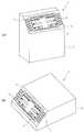
図1は、本実施形態に係る電位治療装置を示す斜視図であり、図2は、本実施形態に係る電位治療装置の内部構造を示すブロック図であり、図3は、本実施形態に係る電位治療装置における制御部の構造を示すブロック図であり、図4は、本実施形態に係る電位治療装置における画面表示反転処理を示すフローチャートであり、図5は、本実施形態に係る電位治療装置における表示画面を示す概略図である。 FIG. 1 is a perspective view showing an electric potential treatment apparatus according to this embodiment, FIG. 2 is a block diagram showing an internal structure of the electric potential treatment apparatus according to this embodiment, and FIG. 3 is according to this embodiment. FIG. 4 is a block diagram showing a structure of a control unit in the potential therapy apparatus, FIG. 4 is a flowchart showing screen display inversion processing in the potential therapy apparatus according to the present embodiment, and FIG. 5 is a potential therapy apparatus according to the present embodiment. It is the schematic which shows the display screen in.
図1に示すように、本実施形態に係る電位治療装置1は、電位治療装置本体2と、電床と、電床と電位治療装置1とを電気的に接続するプラグコードとを備える。 As shown in FIG. 1, the electric
電位治療装置本体2は、その正面側の上部から下方に向けて傾斜面3を有する略直方体形状をなしており、かかる傾斜面3には、液晶ディスプレイ4が設けられている。電位治療装置本体2の正面側に設けた傾斜面3に液晶ディスプレイ4を配置することで、電位治療装置1を立てた状態であっても、電位治療装置1の背面側が底面に向くようにして横に倒した状態であっても、液晶ディスプレイ4を確実に視認しやくすなっている。 The electric potential treatment device
液晶ディスプレイ4の左側及び右側には、電位治療装置1の各種設定等を行うための複数の操作ボタン(本実施形態においては左右3つずつ)5と、各操作ボタン5の上側及び下側に各操作ボタン5の機能を表示する機能表示部6とが設けられている。 On the left and right sides of the
本実施形態に係る電位治療装置1の内部構造について説明する。
図2に示すように、本実施形態に係る電位治療装置1は、制御部10と、制御部10に接続される操作部11、タイマー12、受信部13、音声IC14及び画像IC15と、音声IC14に接続されるスピーカ141と、画像IC15に接続される液晶ディスプレイ(LCD,Liquid Crystal Display)4と、制御部10に接続される正弦波発生器(LPF,Low Pass Filter)16と、正弦波発生器16及び制御部10に接続される可変抵抗器17と、正弦波発生器16及び可変抵抗器17を介して制御部10に接続される増幅器18と、増幅器18にスイッチ19を介して接続される第1のトランス20及び第2のトランス21と、第1のトランス20及び第2のトランス21のそれぞれに接続される第1のコネクタ22及び第2のコネクタ23と、第1のコネクタ22及び第2のコネクタ23のそれぞれに接続される第1のセンサ24及び第2のセンサ25と、第1のコネクタ22に接続される電床26と、第2のコネクタ23に接続される電位治療用プローブ27と、制御部10に接続される傾きセンサ28とを備えている。The internal structure of the
As shown in FIG. 2, the
図3に示すように、制御部10は、CPU101、主記憶装置102及び補助記憶装置103から構成される。主記憶装置102は、出力電圧及び当該電圧の出力時間を制御する制御プログラム、電位治療装置1を作動させるための作動プログラム、液晶ディスプレイ4に表示された画面を反転表示させるための指示プログラム等を記憶する。 As illustrated in FIG. 3, the
CPU101は、主記憶装置102に記憶されているプログラムに従って、電位治療装置1に設けられた各構成要素との間で信号の入出力を行う。また、CPU101は、主記憶装置102に記憶されている制御プログラムに従って、電圧制御データ及び時間制御データを生成したり、主記憶装置102に記憶されている指示プログラムに従って、液晶ディスプレイ4に表示する画像を反転させるための反転画像生成信号を画像IC15に送信したりする。また、CPU101は、電圧制御データ及び時間制御データに基づいて、可変抵抗器17を制御する。 The
補助記憶装置103は、例えば、不揮発メモリ等により構成されており、CPU101により生成された電圧制御データと時間制御データとを関連付けて記憶する。 The
正弦波発生器16は、制御部10(CPU101)からの制御信号に基づいて、所定の周波数を有する正弦波を発生させる。 The
可変抵抗器17は、制御部10(CPU101)からの制御信号に基づいて、出力電圧を調整する。可変抵抗器17は、正弦波発生器16より発振された正弦波を所定の出力電圧に調整する。可変抵抗器17は、出力電圧を0〜15Vの範囲で調整する。 The
増幅器18は、入力電圧を増幅して出力する。具体的には、増幅器18は、入力電圧を0〜60Vの範囲で増幅して出力する。 The
第1のトランス20及び第2のトランス21は、入力電圧を変換(昇圧又は降圧)して出力する。第1のトランス20は、入力電圧を0〜9000Vの範囲で変換して出力し、第2のトランス21は、入力電圧を0〜1600Vの範囲で変換して出力する。 The
第1のコネクタ22は、電床26のプラグが挿入されるコネクタであり、第1のコネクタ22に接続されている第1のセンサ24は、第1のコネクタ22に電床26のプラグが挿入されたことを検知し、制御部10に第1の検知信号を送信する。 The first connector 22 is a connector into which the plug of the
第2のコネクタ23は、電位治療用プローブ27のプラグが挿入されるコネクタであり、第2のコネクタ23に接続されている第2のセンサ25は、第2のコネクタ23に電位治療用プローブ27のプラグが挿入されたことを検知し、制御部10に第2の検知信号を送信する。 The second connector 23 is a connector into which the plug of the potential
なお、第1のコネクタ22は電床26専用のコネクタであり、第2のコネクタ23は電位治療用プローブ27専用のコネクタである。したがって、第1のコネクタ22に電位治療用プローブ27のプラグが挿入されたり、第2のコネクタ23に電床26のプラグが挿入されたりすると、第1又は第2のコネクタ22,23は、他のプローブのプラグが挿入されている旨のエラー信号を制御部10に送信する。 The first connector 22 is a connector dedicated to the
操作部11には、複数の操作ボタン5(本実施形態では6つ)及び主電源のスイッチ(図示せず)が設けられている。複数の操作ボタン5は、液晶ディスプレイ4の表示に従って、出力レベル(「高」、「中」、「低」)を設定したり、治療時間(5〜20分)を設定したりすることができる。各操作ボタン5の上側及び下側に設けられている機能表示部6には、各操作ボタン5の各機能が表示されるようになっている。電位治療装置本体2を立てた状態で載置すると、各操作ボタン5の下側の機能表示部6に各操作ボタン5の機能が表示され(図5(A)参照)、電位治療装置本体2を横に倒した状態で載置すると、各操作ボタン5の上側の機能表示部6に各操作ボタン5の機能が表示される(図5(B)参照)。 The
スイッチ19は、電床26又は電位治療用プローブ27に電流を供給するための切替スイッチであり、電床26のプラグが第1のコネクタ22に挿入されたことを第1のセンサ24が検知し、第1の検知信号が制御部10(CPU101)に送信されると、制御部10(CPU101)からの制御信号に従い、スイッチ19が電床26側(第1のトランス20側)に切り替えられる。一方、電位治療用プローブ27のプラグが第2のコネクタ23に挿入されたことを第2のセンサ25が検知し、第2の検知信号が制御部10(CPU101)に送信されると、制御部10(CPU101)からの制御信号に従い、スイッチ19が電位治療用プローブ27側(第2のトランス21側)に切り替えられる。 The
電床26は、例えば、絶縁布の中に導体布を設け、その導体布の一端に端子を介して高圧コードを接続してなるものであり、椅子の座部や足元等に設置される。電位治療用プローブ27は、例えば、導体を備え、導体の一端に端子を介して高圧コードを接続してなるものであり、導体を治療対象部位に接触させることにより、治療対象部位に局所的に電位を印加することができる。 The
本実施形態に係る電位治療装置は、図示しない電源回路を有している。かかる電源回路は、電位治療装置1の主電源のON/OFFを実行するものであり、操作部11にて主電源のスイッチがON又はOFFにされると、その信号がCPU101に送信され、CPU101からの信号に従って、電源回路が電位治療装置1の主電源をON又はOFFにする。 The potential therapy apparatus according to the present embodiment has a power supply circuit (not shown). Such a power supply circuit is used to turn on / off the main power supply of the
タイマー12は、操作部11にて治療時間の設定がなされた場合、制御部10(CPU101)からの制御信号に基づき、設定された治療時間を計時する機能を有する。 The
受信部13は、赤外線を受信し得る赤外線センサを有しており、リモコン29から送信された赤外線信号を受信し、制御部10(CPU101)に送信する。これにより、リモコン29を用いて主電源のON/OFF、出力レベルの設定、治療時間の設定、治療スタート/ストップ等の操作をすることができる。 The receiving
傾きセンサ28は、電位治療装置本体2の鉛直方向に対する傾きを検知すると、制御部10(CPU101)に傾斜検知信号を送信する。このような傾きセンサ28としては、電位治療装置本体2の鉛直方向に対する傾きを検知し得るものであれば特に限定されるものではない。 When the
音声IC14は、制御部10(CPU101)からの制御信号に基づいて、音声データを生成し、当該音声データに基づいて、スピーカ141から音声を出力する。例えば、CPU101から送信される報知信号に基づいて、報知メッセージを音声として出力する。 The
画像IC15は、制御部10(CPU101)からの制御信号に基づいて、画像データを生成し、当該画像データに基づいて、液晶ディスプレイ(LCD)4に画像を表示する。例えば、画像IC15は、制御部10(CPU101)からの操作画像生成信号に基づいて、操作用画像データを生成し、液晶ディスプレイ4に操作用画像を表示したり、制御部10(CPU101)からの反転画像生成信号に基づいて、上下方向で反転させた画像データを生成し、液晶ディスプレイ4に反転画像を表示したりする。 The
次に、本実施形態に係る電位治療装置1における画像反転処理動作について、図4に示すフローチャートを参照して説明する。 Next, the image inversion processing operation in the
まず、ユーザが、操作部11において主電源のスイッチをONにすると、その信号が操作部11からCPU101に送信され、CPU101からの制御信号により電源回路が交流電源から給電し、電位治療装置1の主電源をONにする。 First, when the user turns on the main power switch in the
CPU101は、操作画像生成信号を画像IC15に送信し、画像IC15は、操作用画像データを生成し、液晶ディスプレイ4に操作用画像を表示する。例えば、CPU101は、電位治療による治療方法(全身治療又は局所治療)を選択する画像を液晶ディスプレイ4に表示する(図5(A)参照)。 The
ユーザが、操作部11において操作ボタン5を押下すると、操作部11からCPU101に操作信号が送信され、CPU101は、かかる操作信号を受信すると、主記憶装置102に記憶されている制御プログラムに従って、電圧制御データ及び時間制御データを生成する。例えば、ユーザが全身治療を選択した場合(図5(A)において、液晶ディスプレイ4の左上の操作ボタン5を押下した場合)、CPU101は、主記憶装置102に記憶されている制御プログラムに従って、出力電圧の上限を9000Vとする電圧制御データを生成する。 When the user presses the
CPU101は、生成した電圧制御データ及び時間制御データに基づいて、可変抵抗器17を制御する。これにより、ユーザの身体に電床26から所望の電位が印加され、ユーザに電位治療が施されることになる。 The
ここで、ユーザが、電位治療装置本体2をその背面側が底面に向くようにして横向きにに倒すと、傾きセンサ28が、電位治療装置本体2の鉛直方向に対する傾きを検知し、CPU101に傾斜検知信号を送信する(S01)。CPU101は、傾きセンサ28からの傾斜検知信号を受信すると(S02)、主記憶装置102に記憶されている指示プログラムに従って、反転画像生成信号を生成し、画像IC15に反転画像生成信号を出力する(S03)。 Here, when the user tilts the potential
画像IC15は、反転画像生成信号を受信すると(S04)、液晶ディスプレイ4に現在表示されている画像に関する画像データを反転させた反転画像データを生成し(S05)、当該反転画像データに基づいて、液晶ディスプレイ4に反転画像を表示する(S06)。例えば、電位治療による治療方法を選択する画面(治療方法選択画面)が液晶ディスプレイ4に表示されている場合に電位治療装置本体2をその背面側が底面に向くようにして横向きに倒すと、液晶ディスプレイ4に反転された治療方法選択画面が表示される(図5(A),(B)参照)。 When receiving the inverted image generation signal (S04), the
また、CPU101は、画像IC15に反転画像生成信号を出力するとともに(S03)、複数の操作ボタン5の機能を変更し、変更した操作ボタン5の機能を、機能表示部6に表示する。これにより、液晶ディスプレイ4に表示されている画像が反転されて表示されたときに、複数の操作ボタン5の相対的な位置関係が変更されることがないため、電位治療装置1を操作性に優れたものとすることができる。 In addition, the
以上説明したように、本実施形態に係る電位治療装置1は、傾きセンサ28が電位治療装置本体2の鉛直方向に対する傾きを検知すると、液晶ディスプレイ4に表示されている画面表示を上下方向に反転して表示することができるため、電床26に横になったままの状態でも、液晶ディスプレイ4の画面表示を確実に視認することができるとともに、操作性に優れたものとなっている。 As described above, in the
しかも、本実施形態に係る電位治療装置1は、傾きセンサ28による検知に基づいて、操作部11の各操作ボタン5の機能が変更されるとともに、各操作ボタン5の上部(又は下部)に設けられている機能表示部6に表示されている各操作ボタン5の機能表示を消去し、下部(又は上部)に設けられている機能表示部6に各操作ボタン5の変更後の機能が表示されるため、液晶ディスプレイ4の画面表示が上下方向に反転して表示されたとしても、電位治療装置1の操作性が変わることはない。 In addition, the
以上説明した実施形態は、本発明の理解を容易にするために記載されたものであって、本発明を限定するために記載されたものではない。したがって、上記実施形態に開示された各要素は、本発明の技術的範囲に属する全ての設計変更や均等物をも含む趣旨である。 The embodiment described above is described for facilitating understanding of the present invention, and is not described for limiting the present invention. Therefore, each element disclosed in the above embodiment is intended to include all design changes and equivalents belonging to the technical scope of the present invention.
例えば、上記実施形態に係る電位治療装置1は、傾きセンサ28からの傾斜検出信号に基づいて、液晶ディスプレイ4に表示される画像を上下方向に反転させるための信号を生成しているが、これに限定されるものではなく、例えば、傾きセンサ28からの傾斜検出信号に基づいて、電位治療装置1の動作を停止するようにしてもよい。これにより、例えば、電位治療装置1による電位治療中に地震等により電位治療装置1が倒れた場合であっても、電位治療装置1の動作が停止することで、安全に電位治療装置1を使用することができる。 For example, the
また、上記実施形態に係る電位治療装置1は、液晶ディスプレイ4の左側及び右側に複数の操作ボタン5を設けているが、これに限定されるものではなく、例えば、液晶ディスプレイ4がタッチパネルを備えるようにし、当該タッチパネルに接触することにより操作できるようにしてもよい。 Moreover, although the electric
さらに、上記実施形態においては、電床26又は電位治療用プローブ27を用いて電位治療を行うことのできる電位治療装置1を例に挙げて説明したが、これに限定されるものではなく、例えば、1又は2以上の低周波治療パッドを用いて低周波治療を行うことのできる低周波治療装置であってもよいし、温熱マットを用いて温熱治療装置であってもよい。また、電位治療、低周波治療、温熱治療のいずれかを行うことのできる組み合わせ電気治療装置であってもよい。 Furthermore, in the said embodiment, although demonstrated taking the case of the electric
1…電位治療装置(電気治療装置)
2…電位治療装置本体(電気治療装置本体)
3…傾斜面
4…液晶ディスプレイ
5…操作ボタン
6…機能表示部
10…制御部
101…CPU
102…主記憶装置
103…補助記憶装置
11…操作部
12…タイマー
13…受信部
14…音声IC
141…スピーカ
15…画像IC
16…正弦波発生器
17…可変抵抗器
18…増幅器
19…スイッチ
20…第1のトランス
21…第2のトランス
22…第1のコネクタ
23…第2のコネクタ
24…第1のセンサ
25…第2のセンサ
26…電床
27…電位治療用プローブ
28…傾きセンサ
29…リモコン1 ... Potential therapy device (electric therapy device)
2 ... Electric potential therapy device (electric therapy device)
DESCRIPTION OF
DESCRIPTION OF
141 ...
16 ...
Claims (4)
Translated fromJapanese前記電気治療装置本体に設けられた画像表示部と、
前記電気治療装置本体の鉛直方向に対する傾きを検出する傾斜検出部と、
前記傾斜検出部からの検出信号に基づいて、前記画像表示部に表示されている画像に関する画像データを上下方向に反転した反転画像データを生成し、当該反転画像データに基づいて上下方向に反転した画像を前記画像表示部に表示する表示切替部と、
前記画像表示部の左側及び右側のそれぞれに縦方向に同数ずつ一列に配列された、前記電気治療装置における設定を行うための複数の操作ボタンと、
前記複数の操作ボタンのそれぞれの機能を変更するボタン機能変更部と
を備え、
前記ボタン機能変更部が、前記画像表示部に上下方向に反転した画像が表示されたときに、前記複数の操作ボタンのそれぞれの機能と前記画像表示部との間の相対的な位置関係が変更されないように、当該複数の操作ボタンのそれぞれの機能を変更することを特徴とする電気治療装置。An electrotherapy device body;
An image display unit provided in the electrotherapy apparatus body;
An inclination detection unit for detecting an inclination of the electrotherapy apparatus main body with respect to a vertical direction;
Based on the detection signal from the tilt detection unit,the image data to generate inverted image data by inverting the vertical direction about the image displayed on the image displayunit, reversed in the vertical direction on the basis of the inverted image data A display switching unitfor displayingthe image that has been displayed on theimage display unit ;
A plurality of operation buttons for performing settings in the electrotherapy apparatus, arranged in a line in the vertical direction on each of the left and right sides of the image display unit;
A button function changing unit for changing the function of each of the plurality of operation buttons;
With
When the button function changing unit displays a vertically inverted image on the image display unit, the relative positional relationship between the function of each of the plurality of operation buttons and the image display unit is changed. The electrotherapy apparatus is characterizedin thatthe function of each of the plurality of operation buttons is changed so as not to be performed.
前記画像表示部が、前記傾斜面に設けられていることを特徴とする請求項1に記載の電気治療装置。On the front side of the electrotherapy apparatus main body, an inclined surface that is inclined downward at a predetermined angle from the upper end is provided,
The electrotherapy apparatus according to claim 1, wherein the image display unit is provided on the inclined surface.
前記ボタン機能変更部により前記複数の操作ボタンのそれぞれの機能が変更された場合に、変更された前記複数の操作ボタンのそれぞれの機能に対応するように、前記ボタン機能表示部の表示を変更するボタン表示変更部と
をさらに備えることを特徴とする請求項1又は2に記載の電気治療装置。A button function display unit that is provided adjacent to each of the plurality of operation buttons and displays a function of the operation button;
When the function of each of the plurality of operation buttons is changed by the button function changing unit, the display of the button function display unit is changed so as to correspond to the function of each of the changed operation buttons. electrotherapy device according to claim1 or 2, characterized by further comprising a button display changing unit.
前記ボタン表示変更部は、前記ボタン機能変更部により前記複数の操作ボタンの機能が変更された場合に、前記複数の操作ボタンのそれぞれの上部又は下部のボタン機能表示部に表示されていた前記操作ボタンの機能表示を消去するとともに、前記複数の操作ボタンのそれぞれの下部又は上部のボタン機能表示部に、変更された前記操作ボタンの機能を表示することを特徴とする請求項3に記載の電気治療装置。The button function display section is provided on each of the upper and lower portions of the plurality of operation buttons,
The button display change unit is configured to display the operation displayed on the upper or lower button function display unit of each of the plurality of operation buttons when the function of the plurality of operation buttons is changed by the button function change unit. 4. The electric function according to claim3 , wherein the function display of the button is erased, and the changed function of the operation button is displayed on a button function display section below or above each of the plurality of operation buttons. Therapeutic device.
Priority Applications (2)
| Application Number | Priority Date | Filing Date | Title |
|---|---|---|---|
| JP2006350666AJP4183266B2 (en) | 2006-12-26 | 2006-12-26 | Electrotherapy equipment |
| PCT/JP2007/072912WO2008078495A1 (en) | 2006-12-26 | 2007-11-28 | Electrotherapy apparatus |
Applications Claiming Priority (1)
| Application Number | Priority Date | Filing Date | Title |
|---|---|---|---|
| JP2006350666AJP4183266B2 (en) | 2006-12-26 | 2006-12-26 | Electrotherapy equipment |
Publications (2)
| Publication Number | Publication Date |
|---|---|
| JP2008161217A JP2008161217A (en) | 2008-07-17 |
| JP4183266B2true JP4183266B2 (en) | 2008-11-19 |
Family
ID=39562288
Family Applications (1)
| Application Number | Title | Priority Date | Filing Date |
|---|---|---|---|
| JP2006350666AActiveJP4183266B2 (en) | 2006-12-26 | 2006-12-26 | Electrotherapy equipment |
Country Status (2)
| Country | Link |
|---|---|
| JP (1) | JP4183266B2 (en) |
| WO (1) | WO2008078495A1 (en) |
Families Citing this family (3)
| Publication number | Priority date | Publication date | Assignee | Title |
|---|---|---|---|---|
| JP6078823B2 (en)* | 2012-09-13 | 2017-02-15 | オージー技研株式会社 | Electrical stimulator |
| JP5813727B2 (en)* | 2013-11-01 | 2015-11-17 | コスモヘルス株式会社 | Potential therapy device |
| CN107866002A (en)* | 2017-12-19 | 2018-04-03 | 梁叶青 | A kind of magnetic based on wireless mode shakes thermal cure instrument |
Family Cites Families (5)
| Publication number | Priority date | Publication date | Assignee | Title |
|---|---|---|---|---|
| JPH0477779A (en)* | 1990-07-19 | 1992-03-11 | Kubota Corp | Display device |
| JP2005013592A (en)* | 2003-06-27 | 2005-01-20 | Japan Esthetique Kyokai:Kk | Beauty appliance |
| JP2006011836A (en)* | 2004-06-25 | 2006-01-12 | Sony Corp | Reproduction device |
| JP3943562B2 (en)* | 2004-07-30 | 2007-07-11 | 東洋プライウッド株式会社 | Floor heating device with potential generating function and potential generating function auxiliary device |
| JP2006247082A (en)* | 2005-03-10 | 2006-09-21 | Yusen:Kk | Electrostatic potential therapy apparatus |
- 2006
- 2006-12-26JPJP2006350666Apatent/JP4183266B2/enactiveActive
- 2007
- 2007-11-28WOPCT/JP2007/072912patent/WO2008078495A1/enactiveApplication Filing
Also Published As
| Publication number | Publication date |
|---|---|
| JP2008161217A (en) | 2008-07-17 |
| WO2008078495A1 (en) | 2008-07-03 |
Similar Documents
| Publication | Publication Date | Title |
|---|---|---|
| KR101324721B1 (en) | A treatment apparatus using radio frequency energy | |
| JP4179625B2 (en) | Potential therapy device and combination electrotherapy device | |
| JP4183266B2 (en) | Electrotherapy equipment | |
| KR101743706B1 (en) | A treatment apparatus using radio frequency energy | |
| CN112584893A (en) | Terminal device, electro-therapeutic apparatus and treatment system | |
| JP2008119310A (en) | Low-frequency therapy equipment | |
| TWI631970B (en) | Potential therapy device | |
| KR200477228Y1 (en) | Multifunctional low frequency foot heating stimulater | |
| JP2015150182A (en) | Electrostimulator | |
| JP2025101680A (en) | current stimulator | |
| KR100346349B1 (en) | Medical treatment system of low frequency with function of heating | |
| JP4217814B2 (en) | Potential therapy device | |
| JP4711665B2 (en) | Combination therapy device | |
| US20250186809A1 (en) | Ultrasound treatment device and method for controlling same | |
| JP2002126102A (en) | Electrotherapeutic instrument | |
| WO2020183929A1 (en) | Application device and application method | |
| WO2020183930A1 (en) | Application device and application method | |
| JP2007111186A (en) | Potential therapeutic apparatus | |
| KR20250098242A (en) | Treatment Device Capable of Efficient Control of Electrical Signals | |
| WO2020183927A1 (en) | Electrical stimulation applying device and electrical stimulation applying method | |
| JP2002126097A (en) | Electric therapeutical device | |
| JP4403528B2 (en) | Electric therapy device | |
| JP2000271231A (en) | Chair-shaped potential therapeutic apparatus | |
| JP2002143324A (en) | Electric potential therapeutic apparatus | |
| JP2020146294A (en) | Electric stimulus application device and electric stimulus application method |
Legal Events
| Date | Code | Title | Description |
|---|---|---|---|
| A871 | Explanation of circumstances concerning accelerated examination | Free format text:JAPANESE INTERMEDIATE CODE: A871 Effective date:20080509 | |
| A975 | Report on accelerated examination | Free format text:JAPANESE INTERMEDIATE CODE: A971005 Effective date:20080515 | |
| A131 | Notification of reasons for refusal | Free format text:JAPANESE INTERMEDIATE CODE: A131 Effective date:20080521 | |
| A521 | Written amendment | Free format text:JAPANESE INTERMEDIATE CODE: A523 Effective date:20080718 | |
| TRDD | Decision of grant or rejection written | ||
| A01 | Written decision to grant a patent or to grant a registration (utility model) | Free format text:JAPANESE INTERMEDIATE CODE: A01 Effective date:20080827 | |
| A01 | Written decision to grant a patent or to grant a registration (utility model) | Free format text:JAPANESE INTERMEDIATE CODE: A01 | |
| A61 | First payment of annual fees (during grant procedure) | Free format text:JAPANESE INTERMEDIATE CODE: A61 Effective date:20080901 | |
| FPAY | Renewal fee payment (event date is renewal date of database) | Free format text:PAYMENT UNTIL: 20110912 Year of fee payment:3 | |
| R150 | Certificate of patent or registration of utility model | Ref document number:4183266 Country of ref document:JP Free format text:JAPANESE INTERMEDIATE CODE: R150 Free format text:JAPANESE INTERMEDIATE CODE: R150 | |
| S531 | Written request for registration of change of domicile | Free format text:JAPANESE INTERMEDIATE CODE: R313531 | |
| FPAY | Renewal fee payment (event date is renewal date of database) | Free format text:PAYMENT UNTIL: 20110912 Year of fee payment:3 | |
| R350 | Written notification of registration of transfer | Free format text:JAPANESE INTERMEDIATE CODE: R350 | |
| FPAY | Renewal fee payment (event date is renewal date of database) | Free format text:PAYMENT UNTIL: 20120912 Year of fee payment:4 | |
| R250 | Receipt of annual fees | Free format text:JAPANESE INTERMEDIATE CODE: R250 | |
| FPAY | Renewal fee payment (event date is renewal date of database) | Free format text:PAYMENT UNTIL: 20120912 Year of fee payment:4 | |
| FPAY | Renewal fee payment (event date is renewal date of database) | Free format text:PAYMENT UNTIL: 20130912 Year of fee payment:5 | |
| R250 | Receipt of annual fees | Free format text:JAPANESE INTERMEDIATE CODE: R250 | |
| R250 | Receipt of annual fees | Free format text:JAPANESE INTERMEDIATE CODE: R250 | |
| R250 | Receipt of annual fees | Free format text:JAPANESE INTERMEDIATE CODE: R250 | |
| R250 | Receipt of annual fees | Free format text:JAPANESE INTERMEDIATE CODE: R250 | |
| R250 | Receipt of annual fees | Free format text:JAPANESE INTERMEDIATE CODE: R250 | |
| R250 | Receipt of annual fees | Free format text:JAPANESE INTERMEDIATE CODE: R250 | |
| R250 | Receipt of annual fees | Free format text:JAPANESE INTERMEDIATE CODE: R250 | |
| R250 | Receipt of annual fees | Free format text:JAPANESE INTERMEDIATE CODE: R250 | |
| R250 | Receipt of annual fees | Free format text:JAPANESE INTERMEDIATE CODE: R250 |