JP4183021B1 - Compressor and refrigeration equipment - Google Patents
Compressor and refrigeration equipmentDownload PDFInfo
- Publication number
- JP4183021B1 JP4183021B1JP2008150617AJP2008150617AJP4183021B1JP 4183021 B1JP4183021 B1JP 4183021B1JP 2008150617 AJP2008150617 AJP 2008150617AJP 2008150617 AJP2008150617 AJP 2008150617AJP 4183021 B1JP4183021 B1JP 4183021B1
- Authority
- JP
- Japan
- Prior art keywords
- screw rotor
- compressor
- economizer
- economizer port
- compression chamber
- Prior art date
- Legal status (The legal status is an assumption and is not a legal conclusion. Google has not performed a legal analysis and makes no representation as to the accuracy of the status listed.)
- Expired - Fee Related
Links
Images


Classifications
- F—MECHANICAL ENGINEERING; LIGHTING; HEATING; WEAPONS; BLASTING
- F04—POSITIVE - DISPLACEMENT MACHINES FOR LIQUIDS; PUMPS FOR LIQUIDS OR ELASTIC FLUIDS
- F04C—ROTARY-PISTON, OR OSCILLATING-PISTON, POSITIVE-DISPLACEMENT MACHINES FOR LIQUIDS; ROTARY-PISTON, OR OSCILLATING-PISTON, POSITIVE-DISPLACEMENT PUMPS
- F04C18/00—Rotary-piston pumps specially adapted for elastic fluids
- F04C18/08—Rotary-piston pumps specially adapted for elastic fluids of intermeshing-engagement type, i.e. with engagement of co-operating members similar to that of toothed gearing
- F04C18/12—Rotary-piston pumps specially adapted for elastic fluids of intermeshing-engagement type, i.e. with engagement of co-operating members similar to that of toothed gearing of other than internal-axis type
- F04C18/14—Rotary-piston pumps specially adapted for elastic fluids of intermeshing-engagement type, i.e. with engagement of co-operating members similar to that of toothed gearing of other than internal-axis type with toothed rotary pistons
- F04C18/16—Rotary-piston pumps specially adapted for elastic fluids of intermeshing-engagement type, i.e. with engagement of co-operating members similar to that of toothed gearing of other than internal-axis type with toothed rotary pistons with helical teeth, e.g. chevron-shaped, screw type
- F—MECHANICAL ENGINEERING; LIGHTING; HEATING; WEAPONS; BLASTING
- F04—POSITIVE - DISPLACEMENT MACHINES FOR LIQUIDS; PUMPS FOR LIQUIDS OR ELASTIC FLUIDS
- F04C—ROTARY-PISTON, OR OSCILLATING-PISTON, POSITIVE-DISPLACEMENT MACHINES FOR LIQUIDS; ROTARY-PISTON, OR OSCILLATING-PISTON, POSITIVE-DISPLACEMENT PUMPS
- F04C18/00—Rotary-piston pumps specially adapted for elastic fluids
- F04C18/48—Rotary-piston pumps with non-parallel axes of movement of co-operating members
- F04C18/50—Rotary-piston pumps with non-parallel axes of movement of co-operating members the axes being arranged at an angle of 90 degrees
- F04C18/52—Rotary-piston pumps with non-parallel axes of movement of co-operating members the axes being arranged at an angle of 90 degrees of intermeshing engagement type, i.e. with engagement of co-operating members similar to that of toothed gearing
- F—MECHANICAL ENGINEERING; LIGHTING; HEATING; WEAPONS; BLASTING
- F04—POSITIVE - DISPLACEMENT MACHINES FOR LIQUIDS; PUMPS FOR LIQUIDS OR ELASTIC FLUIDS
- F04C—ROTARY-PISTON, OR OSCILLATING-PISTON, POSITIVE-DISPLACEMENT MACHINES FOR LIQUIDS; ROTARY-PISTON, OR OSCILLATING-PISTON, POSITIVE-DISPLACEMENT PUMPS
- F04C28/00—Control of, monitoring of, or safety arrangements for, pumps or pumping installations specially adapted for elastic fluids
- F04C28/10—Control of, monitoring of, or safety arrangements for, pumps or pumping installations specially adapted for elastic fluids characterised by changing the positions of the inlet or outlet openings with respect to the working chamber
- F04C28/12—Control of, monitoring of, or safety arrangements for, pumps or pumping installations specially adapted for elastic fluids characterised by changing the positions of the inlet or outlet openings with respect to the working chamber using sliding valves
- F—MECHANICAL ENGINEERING; LIGHTING; HEATING; WEAPONS; BLASTING
- F04—POSITIVE - DISPLACEMENT MACHINES FOR LIQUIDS; PUMPS FOR LIQUIDS OR ELASTIC FLUIDS
- F04C—ROTARY-PISTON, OR OSCILLATING-PISTON, POSITIVE-DISPLACEMENT MACHINES FOR LIQUIDS; ROTARY-PISTON, OR OSCILLATING-PISTON, POSITIVE-DISPLACEMENT PUMPS
- F04C28/00—Control of, monitoring of, or safety arrangements for, pumps or pumping installations specially adapted for elastic fluids
- F04C28/24—Control of, monitoring of, or safety arrangements for, pumps or pumping installations specially adapted for elastic fluids characterised by using valves controlling pressure or flow rate, e.g. discharge valves or unloading valves
- F04C28/26—Control of, monitoring of, or safety arrangements for, pumps or pumping installations specially adapted for elastic fluids characterised by using valves controlling pressure or flow rate, e.g. discharge valves or unloading valves using bypass channels
Landscapes
- Engineering & Computer Science (AREA)
- Mechanical Engineering (AREA)
- General Engineering & Computer Science (AREA)
- Physics & Mathematics (AREA)
- Fluid Mechanics (AREA)
- Applications Or Details Of Rotary Compressors (AREA)
Abstract
Translated fromJapaneseDescription
Translated fromJapaneseこの発明は、圧縮機および冷凍装置に関する。 The present invention relates to a compressor and a refrigeration apparatus.
従来、圧縮機としては、スクリューロータと、エコノマイザーポートを有するシリンダとを備え、このエコノマイザーポートを、上記スクリューロータと上記シリンダとの間の圧縮室が密閉される前に、この圧縮室に連通するものがある(特開2005−83260号公報:特許文献1参照)。
しかしながら、上記従来の圧縮機では、上記エコノマイザーポートの開口タイミング、つまり、上記エコノマイザーポートの位置は、上記スクリューロータの回転数に関係なく一定に固定されているため、上記スクリューロータの回転数によっては、上記エコノマイザーポートからの冷媒の吸入量を多くできず、この冷媒による冷却効果が低減して、エコノマイザー効果を最大限に利用することができない問題があった。 However, in the conventional compressor, the opening timing of the economizer port, that is, the position of the economizer port is fixed regardless of the rotational speed of the screw rotor. In some cases, the amount of refrigerant sucked from the economizer port cannot be increased, the cooling effect of the refrigerant is reduced, and the economizer effect cannot be fully utilized.
そこで、この発明の課題は、上記スクリューロータの回転数に関係なく、エコノマイザー効果を最大限に利用できる圧縮機を提供することにある。 Accordingly, an object of the present invention is to provide a compressor that can make the most of the economizer effect regardless of the rotational speed of the screw rotor.
上記課題を解決するため、この発明の圧縮機は、
ケーシングと、このケーシングに嵌合されたスクリューロータとを備え、
上記ケーシングと上記スクリューロータとの間に形成された圧縮室に冷媒を吐出するためのエコノマイザーポートが設けられ、
上記スクリューロータの回転数が大きくなるほど、上記エコノマイザーポートの上記圧縮室への開口タイミングを早くする制御部を有することを特徴としている。In order to solve the above problems, the compressor of the present invention is:
A casing and a screw rotor fitted to the casing;
An economizer port for discharging refrigerant into a compression chamber formed between the casing and the screw rotor;
It has a control part which makes the opening timing of the said economizer port to the said compression chamber earlier, so that the rotation speed of the said screw rotor becomes large.
この発明の圧縮機によれば、上記スクリューロータの回転数が大きくなるほど、上記エコノマイザーポートの上記圧縮室への開口タイミングを早くする上記制御部を有するので、上記スクリューロータの高速運転時には、上記圧縮室が密閉される(上記スクリューロータの溝を閉じきる)よりも早く、上記エコノマイザーポートを開口する一方、上記スクリューロータの低速運転時には、上記エコノマイザーポートを遅く開口する。 According to the compressor of the present invention, as the rotational speed of the screw rotor increases, the control unit that accelerates the opening timing of the economizer port to the compression chamber is provided. The economizer port is opened earlier than the compression chamber is sealed (the groove of the screw rotor is completely closed), while the economizer port is opened late when the screw rotor is operated at a low speed.
したがって、上記エコノマイザーポートから上記圧縮室へ吐出される冷媒が、上記スクリューロータの低圧側へ漏れないようにしつつ、上記エコノマイザーポートから上記圧縮室への冷媒の吸入量を多くできる。 Accordingly, it is possible to increase the amount of refrigerant sucked from the economizer port into the compression chamber while preventing the refrigerant discharged from the economizer port from leaking into the compression chamber to the low pressure side of the screw rotor.
このように、上記スクリューロータの回転数に関係なく、上記エコノマイザーポートからの冷媒の吸入量を多くし、この冷媒による冷却効果を高めて、エコノマイザー効果を最大限に利用できる。 As described above, regardless of the rotational speed of the screw rotor, the amount of refrigerant sucked from the economizer port can be increased, and the cooling effect by the refrigerant can be enhanced to maximize the economizer effect.
また、一実施形態の圧縮機では、上記制御部は、上記スクリューロータの回転数に応じて、上記エコノマイザーポートの位置を、上記スクリューロータの軸に沿って移動する。 Moreover, in the compressor of one Embodiment, the said control part moves the position of the said economizer port along the axis | shaft of the said screw rotor according to the rotation speed of the said screw rotor.
この実施形態の圧縮機によれば、上記制御部は、上記スクリューロータの回転数に応じて、上記エコノマイザーポートの位置を、上記スクリューロータの軸に沿って移動するので、上記エコノマイザーポートの開口タイミングを簡単に制御できる。 According to the compressor of this embodiment, the control unit moves the position of the economizer port along the axis of the screw rotor in accordance with the rotational speed of the screw rotor. The opening timing can be easily controlled.
また、一実施形態の圧縮機では、上記ケーシングと上記スクリューロータとの間に配置され、上記エコノマイザーポートが設けられ、上記スクリューロータの軸に沿って移動可能なスライド部を有し、
上記制御部は、上記スクリューロータの回転数に応じて、上記スライド部を、上記スクリューロータの軸に沿って移動する。Further, in the compressor according to an embodiment, the compressor is disposed between the casing and the screw rotor, the economizer port is provided, and has a slide portion movable along the axis of the screw rotor,
The said control part moves the said slide part along the axis | shaft of the said screw rotor according to the rotation speed of the said screw rotor.
この実施形態の圧縮機によれば、上記制御部は、上記スクリューロータの回転数に応じて、上記エコノマイザーポートが設けられた上記スライド部を、上記スクリューロータの軸に沿って移動するので、簡単な構成で、上記エコノマイザーポートの開口タイミングを簡単に制御できる。 According to the compressor of this embodiment, the control unit moves the slide unit provided with the economizer port along the axis of the screw rotor according to the number of rotations of the screw rotor. The opening timing of the economizer port can be easily controlled with a simple configuration.
また、一実施形態の圧縮機では、上記エコノマイザーポートは、上記スクリューロータの軸に沿って、複数設けられ、
上記制御部は、上記スクリューロータの回転数に応じて、上記複数のエコノマイザーポートを、選択的に、開口する。Further, in the compressor according to one embodiment, a plurality of the economizer ports are provided along the axis of the screw rotor,
The control unit selectively opens the plurality of economizer ports according to the number of rotations of the screw rotor.
この実施形態の圧縮機によれば、上記制御部は、上記スクリューロータの回転数に応じて、上記複数のエコノマイザーポートを、選択的に、開口するので、上記エコノマイザーポートの開口タイミングを簡単に制御できる。 According to the compressor of this embodiment, the control unit selectively opens the plurality of economizer ports according to the number of rotations of the screw rotor, so that the opening timing of the economizer port can be simplified. Can be controlled.
また、この発明の冷凍装置は、
上記圧縮機、凝縮器、過冷却用熱交換器、膨張部および蒸発器を有し、
上記圧縮機、上記凝縮器、上記過冷却用熱交換器、上記膨張部および上記蒸発器は、順次、循環回路を介して、接続され、
上記過冷却用熱交換器と、上記圧縮機の上記エコノマイザーポートとは、エコノマイザーラインにより接続されていることを特徴としている。The refrigeration apparatus of the present invention
The compressor, the condenser, the heat exchanger for supercooling, the expansion unit and the evaporator,
The compressor, the condenser, the supercooling heat exchanger, the expansion unit, and the evaporator are sequentially connected via a circulation circuit,
The supercooling heat exchanger and the economizer port of the compressor are connected by an economizer line.
この発明の冷凍装置によれば、上記圧縮機を有するので、上記圧縮機は、エコノマイザー効果を最大限に利用できて、効率のよい冷凍装置を実現できる。 According to the refrigeration apparatus of the present invention, since the compressor is included, the compressor can utilize the economizer effect to the maximum and realize an efficient refrigeration apparatus.
この発明の圧縮機によれば、上記スクリューロータの回転数が大きくなるほど、上記エコノマイザーポートの上記圧縮室への開口タイミングを早くする上記制御部を有するので、上記スクリューロータの回転数に関係なく、エコノマイザー効果を最大限に利用できる。 According to the compressor of the present invention, as the rotational speed of the screw rotor is increased, the control unit that accelerates the opening timing of the economizer port to the compression chamber is provided, so regardless of the rotational speed of the screw rotor. The economizer effect can be used to the maximum.
この発明の冷凍装置によれば、上記圧縮機を有するので、上記圧縮機は、エコノマイザー効果を最大限に利用できて、効率のよい冷凍装置を実現できる。 According to the refrigeration apparatus of the present invention, since the compressor is included, the compressor can utilize the economizer effect to the maximum and realize an efficient refrigeration apparatus.
以下、この発明を図示の実施の形態により詳細に説明する。 Hereinafter, the present invention will be described in detail with reference to the illustrated embodiments.
(第1の実施形態)
図1は、この発明の圧縮機の第1実施形態である簡略構成図を示している。図2は、圧縮機の簡略平面展開図を示している。図1と図2に示すように、この圧縮機は、ケーシング11と、このケーシング11に嵌合されたスクリューロータ10とを有する。(First embodiment)
FIG. 1 is a simplified configuration diagram showing a first embodiment of a compressor according to the present invention. FIG. 2 shows a simplified plan development view of the compressor. As shown in FIGS. 1 and 2, the compressor includes a
上記スクリューロータ10の軸Lを中心とした両側に、一対のゲートロータ15が配置されている。上記スクリューロータ10には、上記ゲートロータ15が噛合しており、上記スクリューロータ10と上記ゲートロータ15との噛合により、圧縮室12を形成している。つまり、この圧縮機は、いわゆるシングルスクリュー圧縮機である。 A pair of
上記スクリューロータ10は、複数の螺旋状の羽根10bを有し、この隣り合う羽根10b,10bの間に、スクリュー溝10aを有する。上記ゲートロータ15は、複数の歯部15aを有する。上記スクリュー溝10aと上記歯部15aとは、噛合しており、上記スクリュー溝10a、上記歯部15aおよび上記ケーシング11にて区画された空間が、上記圧縮室12を構成する。 The
上記スクリューロータ10が、図2の矢印A方向に回転することで、上記スクリューロータ10の吸入側から吸入した冷媒を、上記圧縮室12にて、圧縮しつつ、上記スクリューロータ10の吐出側へ、送り出す。なお、図1および図2では、紙面左側を、冷媒の吸入側とし、紙面右側を、冷媒の吐出側とする。 When the
この圧縮機には、上記ケーシング11と上記スクリューロータ10との間に形成された上記圧縮室12に冷媒を吐出するためのエコノマイザーポートEP1が、設けられている。このエコノマイザーポートEP1は、二つ設けられ、この二つのエコノマイザーポートEP1は、上記羽根10bに沿って並べられている。 The compressor is provided with an economizer port EP1 for discharging refrigerant to the
この圧縮機は、上記スクリューロータ10の回転数が大きくなるほど、上記エコノマイザーポートEP1の上記圧縮室12への開口タイミングを早くする制御部30を有する。なお、上記スクリューロータ10は、インバータ駆動されている。 The compressor has a
上記制御部30は、上記スクリューロータ10の回転数に応じて、上記エコノマイザーポートEP1の開口位置を、上記スクリューロータ10の軸Lに沿って移動する。 The
具体的に述べると、上記ケーシング11と上記スクリューロータ10との間に、上記スクリューロータ10の軸Lに沿って移動可能なスライド部20が配置されている。 Specifically, a
上記スライド部20は、駆動部21により、上記スクリューロータ10の軸Lに沿って移動される。この駆動部21は、上記スライド部20に取り付けられたスライドロッド22と、上記ケーシング11に取り付けられたシリンダ23と、このシリンダ23に嵌合されたピストン24と、このピストン24に取り付けられたピストンロッド25と、上記スライドロッド22と上記ピストンロッド25とを連結する連結部26とを有する。 The
そして、上記シリンダ23内の上記ピストン24の往復移動により、上記スライド部20を、上記スクリューロータ10の軸Lに沿って往復移動させる。 Then, the
上記スライド部20は、上記ケーシング11の内面に対向する面に、上記スクリューロータ10の軸Lに沿った溝部20aを有する。また、上記スライド部20には、上記溝部20aと上記スクリューロータ10の外面に対向する面とを貫通する孔部20bが、設けられている。 The
この孔部20bにおける上記スクリューロータ10側の開口が、上記スライド部20に設けられた上記エコノマイザーポートEP1に相当する。 The opening on the
上記ケーシング11には、エコノマイザーラインELに接続される貫通孔11aが設けられている。そして、上記エコノマイザーラインEL、上記貫通孔11a、上記溝部20aおよび上記孔部20bが連通して、上記エコノマイザーラインELからの冷媒を、上記エコノマイザーポートEP1から上記圧縮室12に吐出する。 The
上記スライド部20は、上記スクリューロータ10の軸Lに沿って移動しても、上記溝部20aは上記スクリューロータ10の軸Lに沿って形成されているので、上記エコノマイザーラインELからの冷媒を、上記貫通孔11a、上記溝部20aおよび上記孔部20bに、途切れることなく流すことができる。 Even if the
上記制御部30は、上記スクリューロータ10の回転数に応じて、上記駆動部21を制御して、上記スライド部20を、上記スクリューロータ10の軸Lに沿って移動する。 The
つまり、上記スクリューロータ10の回転数が大きい場合、上記制御部30は、上記駆動部21を制御し、上記スライド部20を冷媒の吸入側に移動して、上記エコノマイザーポートEP1の開口タイミングを早くする。一方、上記スクリューロータ10の回転数が小さい場合、上記制御部30は、上記駆動部21を制御し、上記スライド部20を冷媒の吐出側に移動して、上記エコノマイザーポートEP1の開口タイミングを遅くする。 That is, when the number of rotations of the
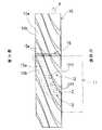
具体的に述べると、図2に示すように、上記スクリューロータ10の回転速度が低速である場合、図2の領域Zに示すように上記圧縮室12が密閉された時点で、上記エコノマイザーポートEP1を、上記圧縮室12に、半開口している。 Specifically, as shown in FIG. 2, when the rotational speed of the
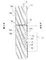
図3に示すように、上記スクリューロータ10の回転速度が中速である場合、図3の領域Zに示すように上記圧縮室12が密閉された時点で、上記エコノマイザーポートEP1を、上記圧縮室12に、全開口している。 As shown in FIG. 3, when the rotational speed of the
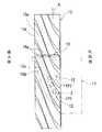
図4に示すように、上記スクリューロータ10の回転速度が高速である場合、図4の領域Zに示すように上記圧縮室12が密閉された時点で、上記エコノマイザーポートEP1を、上記圧縮室12に、全開口している。この高速では、図3の中速の場合に比べて、上記エコノマイザーポートEP1を上記圧縮室12に早く開口しており、つまり、上記エコノマイザーポートEP1を上記圧縮室12が密閉される前に開口している。 As shown in FIG. 4, when the rotational speed of the
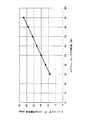
要するに、図5のグラフに示すように、スクリューロータの回転数が大きくなるに従い、エコノマイザーポートの先行開角度を大きくしている。ここで、エコノマイザーポートの先行開角度とは、圧縮室が閉じられた時点のスクリューロータの回転角度を0°とし、圧縮室が閉じられる前に先行してエコノマイザーポートが圧縮室に開口し始めるときのスクリューロータの回転角度をいう。 In short, as shown in the graph of FIG. 5, as the rotation speed of the screw rotor increases, the preceding opening angle of the economizer port is increased. Here, the advance opening angle of the economizer port means that the rotation angle of the screw rotor when the compression chamber is closed is 0 °, and the economizer port opens to the compression chamber before the compression chamber is closed. The rotation angle of the screw rotor when starting.
上記構成の圧縮機によれば、上記スクリューロータ10の回転数が大きくなるほど、上記エコノマイザーポートEP1の上記圧縮室12への開口タイミングを早くする上記制御部30を有するので、上記スクリューロータ10の高速運転時には、上記圧縮室12が密閉される(上記スクリューロータ10の上記スクリュー溝10aを閉じきる)よりも早く、上記エコノマイザーポートEP1を開口する一方、上記スクリューロータ10の低速運転時には、上記エコノマイザーポートEP1を遅く開口する。 According to the compressor having the above-described configuration, the
したがって、上記エコノマイザーポートEP1から上記圧縮室12へ吐出される冷媒が、上記スクリューロータ10の低圧側へ漏れないようにしつつ、上記エコノマイザーポートEP1から上記圧縮室12への冷媒の吸入量を多くできる。 Accordingly, the refrigerant discharged from the economizer port EP1 to the
このように、上記スクリューロータ10の回転数に関係なく、上記エコノマイザーポートEP1からの冷媒の吸入量を多くし、この冷媒による冷却効果を高めて、エコノマイザー効果を最大限に利用できる。 In this way, regardless of the rotational speed of the
つまり、高速回転時では、上記エコノマイザーポートEP1からの噴出冷媒の流速は、一定に対して、上記スクリューロータ10の回転速度が速くなるので、上記スクリュー溝10aの閉じ切りは、早くなり、低圧側への漏れに対して余裕が出てくる。したがって、高速時においては、上記エコノマイザーポートEP1の開口タイミングを早くすることができる。 That is, at the time of high-speed rotation, the flow rate of the refrigerant ejected from the economizer port EP1 is constant, whereas the rotational speed of the
一方、低速回転時では、上記スクリューロータ10の回転速度は、高速時に比べて遅くなるので、閉じきりタイミングを早くしないと、低圧側へ漏れ出すので、上記エコノマイザーポートEP1の開口タイミングを高速に比べて遅らせる必要がある。 On the other hand, at the time of low speed rotation, the rotational speed of the
また、上記構成の圧縮機によれば、上記制御部30は、上記スクリューロータ10の回転数に応じて、上記エコノマイザーポートEP1の位置を、上記スクリューロータ10の軸Lに沿って移動するので、上記エコノマイザーポートEP1の開口タイミングを簡単に制御できる。 Further, according to the compressor configured as described above, the
また、上記制御部30は、上記スクリューロータ10の回転数に応じて、上記エコノマイザーポートEP1が設けられた上記スライド部20を、上記スクリューロータ10の軸Lに沿って移動するので、簡単な構成で、上記エコノマイザーポートEP1の開口タイミングを簡単に制御できる。 Further, since the
(第2の実施形態)
図6Aは、この発明の圧縮機の第2の実施形態を示している。上記第1の実施形態と相違する点を説明すると、この第2の実施形態では、エコノマイザーポートの構造が相違する。なお、その他の構造は、上記第1の実施形態と同じであるため、その説明を省略する。(Second Embodiment)
FIG. 6A shows a second embodiment of the compressor of the present invention. When the difference from the first embodiment is described, the structure of the economizer port is different in the second embodiment. Since other structures are the same as those of the first embodiment, description thereof is omitted.
図6Aに示すように、エコノマイザーポートEP2は、スクリューロータ10の軸Lに沿って、複数設けられている。制御部40は、上記スクリューロータ10の回転数に応じて、上記複数のエコノマイザーポートEP2を、選択的に、開口する。 As shown in FIG. 6A, a plurality of economizer ports EP <b> 2 are provided along the axis L of the
上記各エコノマイザーポートEP2の上流側に、電磁弁41が設けられ、上記制御部40は、上記スクリューロータ10の回転数に応じて、上記電磁弁41を選択的に制御して、上記複数のエコノマイザーポートEP2を、選択的に、開口する。 An
つまり、上記制御部40は、上記スクリューロータ10の回転数が大きくなるにしたがい、吐出側に近い上記電磁弁41を開として、吐出側に近い上記エコノマイザーポートEP2を、開口する。 That is, as the rotational speed of the
具体的に述べると、図6Bに示すように、上記エコノマイザーポートEP2は、羽根10bに沿って、3つ並べられている。上記スクリューロータ10の回転速度が低速である場合、最も吸入側に近い(実線にて示す)エコノマイザーポートEP2のみを開口する。図6Bの領域Zに示すように上記圧縮室12が密閉された時点で、(実線にて示す)上記エコノマイザーポートEP2は、上記圧縮室12に、半開口している。 Specifically, as shown in FIG. 6B, three economizer ports EP2 are arranged along the
図6Cに示すように、上記スクリューロータ10の回転速度が中速である場合、真ん中の(実線にて示す)エコノマイザーポートEP2のみを開口する。図6Cの領域Zに示すように上記圧縮室12が密閉された時点で、(実線にて示す)上記エコノマイザーポートEP2は、上記圧縮室12に、全開口している。 As shown in FIG. 6C, when the rotational speed of the
図6Dに示すように、上記スクリューロータ10の回転速度が高速である場合、最も吐出側に近い(実線にて示す)エコノマイザーポートEP2のみを開口する。図6Dの領域Zに示すように上記圧縮室12が密閉された時点で、(実線にて示す)上記エコノマイザーポートEP2は、上記圧縮室12に、全開口している。この高速では、図6Cの中速の場合に比べて、上記エコノマイザーポートEP2は上記圧縮室12に早く開口しており、つまり、上記エコノマイザーポートEP2は上記圧縮室12が密閉される前に全開口している。 As shown in FIG. 6D, when the rotational speed of the
したがって、上記制御部40は、上記スクリューロータ10の回転数に応じて、上記複数のエコノマイザーポートEP2を、選択的に、開口するので、上記エコノマイザーポートEP2の開口タイミングを簡単に制御できる。 Therefore, the
(第3の実施形態)
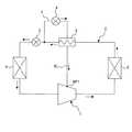
次に、図7に、この発明の冷凍装置の一実施形態を示す。この発明の冷凍装置は、上記第1の実施形態の圧縮機1、凝縮器2、過冷却用熱交換器5、膨張部3および蒸発器4を有する。(Third embodiment)
Next, FIG. 7 shows an embodiment of the refrigeration apparatus of the present invention. The refrigeration apparatus of the present invention includes the
上記圧縮機1、上記凝縮器2、上記過冷却用熱交換器5、上記膨張部3および上記蒸発器4は、順次、循環回路Cを介して、接続されている。上記膨張部3は、例えば、膨張弁やキャピラリーチューブである。 The
つまり、上記圧縮機1、上記凝縮器2、上記膨張部3および上記蒸発器4は、冷凍サイクルを形成している。ここで、この冷凍サイクルを説明すると、上記圧縮機1にて吐出される気相の冷媒は、上記凝縮器2において熱を奪われて、液相状態になり、この液相の冷媒は、上記膨張部3により、減圧されて、気相と液相の二相状態になる。その後、この二相の冷媒(湿りガス)は、上記蒸発器4において熱を与えられて、気相状態になり、この気相の冷媒は、上記圧縮機1にて吸入されて加圧された後に、再び、上記圧縮機1にて吐出される。 That is, the
上記過冷却用熱交換器5と、上記圧縮機1の上記エコノマイザーポートEP1とは、エコノマイザーラインELにより接続されている。 The supercooling
上記過冷却用熱交換器5には、上記循環回路Cにおける上記過冷却用熱交換器5と上記膨張部3との間の部分から分岐された分岐流路7が接続され、この分岐流路7には、過冷却用膨張部6が設けられている。なお、上記過冷却用膨張部6としては、例えば、膨張弁や、キャピラリーチューブを用いる。 Connected to the
上記過冷却用熱交換器5は、上記過冷却用膨張部6の出口側の冷媒と上記循環回路Cの冷媒とを熱交換する。なお、上記分岐流路7を、上記過冷却用熱交換器5の上流側にて上記循環回路Cから分岐するようにしてもよい。 The supercooling
ここで、上記過冷却用熱交換器5の作用を説明すると、上記凝縮器2から出た上記循環回路Cにおける液相の冷媒は、上記分岐流路7に分流される。この分岐流路7における液相の冷媒は、上記過冷却用膨張部6にて減圧されて、気相と液相の二相の冷媒になり、この二相の冷媒は、上記過冷却用熱交換器5を介して、上記循環回路Cの液相の冷媒から熱を奪って、気相の冷媒になり、この気相の冷媒は、上記エコノマイザーラインELを通って、上記エコノマイザーポートEP1から上記圧縮機1に吸入される。このとき、上記循環回路Cにおける液相の冷媒は、上記過冷却用熱交換器5を介して、冷却される。 Here, the operation of the
上記構成の冷凍装置によれば、上記圧縮機1を有するので、上記圧縮機1は、エコノマイザー効果を最大限に利用できて、効率のよい冷凍装置を実現できる。 According to the refrigeration apparatus having the above configuration, since the
(第4の実施形態)
図8B〜図8Eは、この発明の圧縮機のスライド部の他の実施形態を示している。図8Aは、上記第1の実施形態(図1)のスライド部20の平面図を示し、上記第1の実施形態でも説明したとおり、このスライド部20は、溝部20aと、この溝部20aの底面に設けられた孔部20bとを有する。孔部20bは、羽根10bに沿って、2つ並べられている。この孔部20bの開口が、エコノマイザーポートEP1に相当する。(Fourth embodiment)
8B to 8E show other embodiments of the slide portion of the compressor of the present invention. FIG. 8A shows a plan view of the
図8Bに示すスライド部120は、溝部120aと、この溝部120aの底面に設けられた孔部120bとを有する。孔部120bは、1つであり、円形である。この孔部120bの開口が、エコノマイザーポートEP1に相当する。 8B has a groove 120a and a
図8Cに示すスライド部220は、溝部220aと、この溝部220aの底面に設けられた孔部220bとを有する。孔部220bは、羽根10bに沿って、3つ並べられている。この孔部220bの開口が、エコノマイザーポートEP1に相当する。 The
図8Dに示すスライド部320は、溝部320aと、この溝部320aの底面に設けられた孔部320bとを有する。孔部320bは、羽根10bに沿って、4つ並べられている。この孔部320bの開口が、エコノマイザーポートEP1に相当する。孔部320bの径は、吐出側の孔部320bほど、大きい。つまり、羽根10bの幅が、吐出側ほど、広いため、孔部320bの径を、羽根10bの幅に対応して形成することで、エコノマイザーポートEP1の全てを同一タイミングで開閉させることができ、効率を向上できる。 The
図8Eに示すスライド部420は、溝部420aと、この溝部420aの底面に設けられた孔部420bとを有する。孔部420bは、1つであり、羽根10bに沿った長穴である。この孔部420bの開口が、エコノマイザーポートEP1に相当する。孔部420bの幅は、吐出側ほど、広い。つまり、羽根10bの幅が、吐出側ほど、広いため、孔部420bの幅を、羽根10bの幅に対応して形成することで、エコノマイザーポートEP1を全長にわたって同一タイミングで開閉させることができ、効率を向上できる。 8E includes a groove 420a and a
なお、この発明は上述の実施形態に限定されない。例えば、圧縮機は、いわゆるツインスクリュー圧縮機であってもよい。また、エコノマイザーポートの数量の増減は、自由である。また、エコノマイザーポートの形状は、円形以外に、楕円形や長円形等であってもよい。また、上記第3の実施形態に、上記第2の実施形態を、適用してもよい。 In addition, this invention is not limited to the above-mentioned embodiment. For example, the compressor may be a so-called twin screw compressor. The number of economizer ports can be increased or decreased. Further, the shape of the economizer port may be an ellipse or an oval other than a circle. The second embodiment may be applied to the third embodiment.
1 圧縮機
2 凝縮器
3 膨張部
4 蒸発器
5 過冷却用熱交換器
6 過冷却用膨張部
7 分岐流路
10 スクリューロータ
10a スクリュー溝
10b 羽根
11 ケーシング
11a 貫通孔
12 圧縮室
15 ゲートロータ
15a 歯部
20,120,220,320,420 スライド部
20a,120a,220a,320a,420a 溝部
20b,120b,220b,320b,420b 孔部
21 駆動部
22 スライドロッド
23 シリンダ
24 ピストン
25 ピストンロッド
26 連結部
30,40 制御部
41 電磁弁
C 循環回路
EL エコノマイザーライン
EP1,EP2 エコノマイザーポート
L 軸DESCRIPTION OF
Claims (5)
Translated fromJapanese上記ケーシング(11)と上記スクリューロータ(10)との間に形成された圧縮室(12)に冷媒を吐出するためのエコノマイザーポート(EP1,EP2)が設けられ、
上記スクリューロータ(10)の回転数が大きくなるほど、上記エコノマイザーポート(EP1,EP2)の上記圧縮室(12)への開口タイミングを早くする制御部(30,40)を有することを特徴とする圧縮機。A casing (11) and a screw rotor (10) fitted in the casing (11);
Economizer ports (EP1, EP2) for discharging refrigerant to a compression chamber (12) formed between the casing (11) and the screw rotor (10) are provided,
It has a control part (30, 40) which accelerates the opening timing to the said compression chamber (12) of the said economizer port (EP1, EP2), so that the rotation speed of the said screw rotor (10) becomes large. Compressor.
上記制御部(30)は、上記スクリューロータ(10)の回転数に応じて、上記エコノマイザーポート(EP1)の位置を、上記スクリューロータ(10)の軸(L)に沿って移動することを特徴とする圧縮機。The compressor according to claim 1,
The controller (30) moves the position of the economizer port (EP1) along the axis (L) of the screw rotor (10) according to the rotational speed of the screw rotor (10). Features compressor.
上記ケーシング(11)と上記スクリューロータ(10)との間に配置され、上記エコノマイザーポート(EP1)が設けられ、上記スクリューロータ(10)の軸(L)に沿って移動可能なスライド部(20)を有し、
上記制御部(30)は、上記スクリューロータ(10)の回転数に応じて、上記スライド部(20)を、上記スクリューロータ(10)の軸(L)に沿って移動することを特徴とする圧縮機。The compressor according to claim 2, wherein
A slide part (between the casing (11) and the screw rotor (10), provided with the economizer port (EP1) and movable along the axis (L) of the screw rotor (10) ( 20)
The control unit (30) moves the slide unit (20) along the axis (L) of the screw rotor (10) according to the rotational speed of the screw rotor (10). Compressor.
上記エコノマイザーポート(EP2)は、上記スクリューロータ(10)の軸(L)に沿って、複数設けられ、
上記制御部(40)は、上記スクリューロータ(10)の回転数に応じて、上記複数のエコノマイザーポート(EP2)を、選択的に、開口することを特徴とする圧縮機。The compressor according to claim 1,
A plurality of economizer ports (EP2) are provided along the axis (L) of the screw rotor (10),
The said control part (40) selectively opens the said some economizer port (EP2) according to the rotation speed of the said screw rotor (10), The compressor characterized by the above-mentioned.
上記圧縮機(1)、上記凝縮器(2)、上記過冷却用熱交換器(5)、上記膨張部(3)および上記蒸発器(4)は、順次、循環回路(C)を介して、接続され、
上記過冷却用熱交換器(5)と、上記圧縮機(1)の上記エコノマイザーポート(EP1,EP2)とは、エコノマイザーライン(EL)により接続されていることを特徴とする冷凍装置。A compressor (1) according to any one of claims 1 to 4, a condenser (2), a supercooling heat exchanger (5), an expansion section (3) and an evaporator (4),
The compressor (1), the condenser (2), the supercooling heat exchanger (5), the expansion section (3) and the evaporator (4) are sequentially passed through a circulation circuit (C). Connected
The refrigerating apparatus, wherein the supercooling heat exchanger (5) and the economizer ports (EP1, EP2) of the compressor (1) are connected by an economizer line (EL).
Priority Applications (5)
| Application Number | Priority Date | Filing Date | Title |
|---|---|---|---|
| JP2008150617AJP4183021B1 (en) | 2007-06-11 | 2008-06-09 | Compressor and refrigeration equipment |
| EP08765467.9AEP2166229B1 (en) | 2007-06-11 | 2008-06-11 | Compressor, and refrigerating apparatus |
| PCT/JP2008/060688WO2008153061A1 (en) | 2007-06-11 | 2008-06-11 | Compressor, and refrigerating apparatus |
| US12/663,908US8794027B2 (en) | 2007-06-11 | 2008-06-11 | Compressor and refrigerating apparatus |
| CN2008800199605ACN101680450B (en) | 2007-06-11 | 2008-06-11 | Compressors and Refrigerators |
Applications Claiming Priority (2)
| Application Number | Priority Date | Filing Date | Title |
|---|---|---|---|
| JP2007153857 | 2007-06-11 | ||
| JP2008150617AJP4183021B1 (en) | 2007-06-11 | 2008-06-09 | Compressor and refrigeration equipment |
Publications (2)
| Publication Number | Publication Date |
|---|---|
| JP4183021B1true JP4183021B1 (en) | 2008-11-19 |
| JP2009019624A JP2009019624A (en) | 2009-01-29 |
Family
ID=40129666
Family Applications (1)
| Application Number | Title | Priority Date | Filing Date |
|---|---|---|---|
| JP2008150617AExpired - Fee RelatedJP4183021B1 (en) | 2007-06-11 | 2008-06-09 | Compressor and refrigeration equipment |
Country Status (5)
| Country | Link |
|---|---|
| US (1) | US8794027B2 (en) |
| EP (1) | EP2166229B1 (en) |
| JP (1) | JP4183021B1 (en) |
| CN (1) | CN101680450B (en) |
| WO (1) | WO2008153061A1 (en) |
Families Citing this family (12)
| Publication number | Priority date | Publication date | Assignee | Title |
|---|---|---|---|---|
| EP2523496B1 (en) | 2010-01-07 | 2021-07-21 | Nec Corporation | Wireless communication system, radio terminal, radio network, wireless communication method and program |
| CN101979880B (en)* | 2010-04-26 | 2013-07-31 | 上海维尔泰克螺杆机械有限公司 | Screw compressor |
| JP5818522B2 (en)* | 2011-06-13 | 2015-11-18 | 三菱電機株式会社 | Screw compressor |
| WO2014192114A1 (en)* | 2013-05-30 | 2014-12-04 | 三菱電機株式会社 | Screw compressor and refrigeration cycle device |
| EP3006740B1 (en)* | 2013-05-30 | 2018-11-14 | Mitsubishi Electric Corporation | Screw compressor and refrigeration cycle device |
| WO2016046908A1 (en)* | 2014-09-24 | 2016-03-31 | 三菱電機株式会社 | Screw compressor and refrigeration cycle device |
| EP3199814B1 (en)* | 2014-09-24 | 2021-01-06 | Mitsubishi Electric Corporation | Screw compressor and refrigeration cycle device |
| EP3225848A4 (en)* | 2014-11-26 | 2018-10-17 | Mitsubishi Electric Corporation | Screw compressor and refrigeration cycle device |
| WO2018037469A1 (en)* | 2016-08-23 | 2018-03-01 | 三菱電機株式会社 | Screw compressor and refrigeration cycle device |
| CN106979160A (en)* | 2017-04-26 | 2017-07-25 | 珠海格力电器股份有限公司 | Screw compressor, air conditioner and refrigerating device |
| WO2019207945A1 (en)* | 2018-04-26 | 2019-10-31 | 株式会社日立産機システム | Liquid supply type screw compressor |
| EP3660314B1 (en)* | 2018-10-09 | 2022-03-02 | Mayekawa Mfg. Co., Ltd. | Screw compressor and refrigeration device |
Family Cites Families (25)
| Publication number | Priority date | Publication date | Assignee | Title |
|---|---|---|---|---|
| GB1171291A (en)* | 1965-10-12 | 1969-11-19 | Svenska Rotor Maskiner Ab | Screw Rotor Machines |
| GB1352698A (en)* | 1970-04-16 | 1974-05-08 | Hall Thermotank Int Ltd | Refrigeration |
| JPS5140641B2 (en)* | 1971-12-16 | 1976-11-05 | ||
| CS189674B2 (en)* | 1973-11-19 | 1979-04-30 | Hall Thermotank Prod Ltd | Method of and apparatus for compressing gas or steam and for lubricating the compressing machine |
| US3913346A (en)* | 1974-05-30 | 1975-10-21 | Dunham Bush Inc | Liquid refrigerant injection system for hermetic electric motor driven helical screw compressor |
| USRE30499E (en)* | 1974-11-19 | 1981-02-03 | Dunham-Bush, Inc. | Injection cooling of screw compressors |
| JPS5720864Y2 (en) | 1977-01-12 | 1982-05-06 | ||
| JPS5481513A (en)* | 1977-12-09 | 1979-06-29 | Hitachi Ltd | Scroll compressor |
| FR2459385A1 (en)* | 1979-06-19 | 1981-01-09 | Zimmern Bernard | PROCESS FOR SUPERIMENTING AND ADJUSTING A SINGLE SCREW COMPRESSOR |
| JPS5738692A (en) | 1980-08-20 | 1982-03-03 | Ebara Corp | Oil returning device of refrigerator |
| JPS5732369U (en)* | 1981-06-16 | 1982-02-20 | ||
| JPS60164693A (en)* | 1984-02-06 | 1985-08-27 | Daikin Ind Ltd | Screw compressor capacity control device |
| JPS61272486A (en) | 1985-05-27 | 1986-12-02 | Kobe Steel Ltd | Screw compressor |
| JPH0413436Y2 (en) | 1986-07-03 | 1992-03-27 | ||
| JP2618501B2 (en)* | 1989-10-30 | 1997-06-11 | 株式会社日立製作所 | Low-temperature scroll type refrigerator |
| JP2646894B2 (en)* | 1991-07-12 | 1997-08-27 | 三菱電機株式会社 | Refrigeration cycle device |
| US5329788A (en)* | 1992-07-13 | 1994-07-19 | Copeland Corporation | Scroll compressor with liquid injection |
| US5722257A (en)* | 1995-10-11 | 1998-03-03 | Denso Corporation | Compressor having refrigerant injection ports |
| US6182467B1 (en)* | 1999-09-27 | 2001-02-06 | Carrier Corporation | Lubrication system for screw compressors using an oil still |
| US6430959B1 (en)* | 2002-02-11 | 2002-08-13 | Scroll Technologies | Economizer injection ports extending through scroll wrap |
| JP4330369B2 (en)* | 2002-09-17 | 2009-09-16 | 株式会社神戸製鋼所 | Screw refrigeration equipment |
| JP4147891B2 (en)* | 2002-10-16 | 2008-09-10 | ダイキン工業株式会社 | Variable VI inverter screw compressor |
| JP4140488B2 (en)* | 2003-09-09 | 2008-08-27 | ダイキン工業株式会社 | Screw compressor and refrigeration equipment |
| US20080184733A1 (en)* | 2007-02-05 | 2008-08-07 | Tecumseh Products Company | Scroll compressor with refrigerant injection system |
| US8516850B2 (en)* | 2008-07-14 | 2013-08-27 | Johnson Controls Technology Company | Motor cooling applications |
- 2008
- 2008-06-09JPJP2008150617Apatent/JP4183021B1/ennot_activeExpired - Fee Related
- 2008-06-11EPEP08765467.9Apatent/EP2166229B1/ennot_activeNot-in-force
- 2008-06-11CNCN2008800199605Apatent/CN101680450B/ennot_activeExpired - Fee Related
- 2008-06-11USUS12/663,908patent/US8794027B2/ennot_activeExpired - Fee Related
- 2008-06-11WOPCT/JP2008/060688patent/WO2008153061A1/enactiveApplication Filing
Also Published As
| Publication number | Publication date |
|---|---|
| JP2009019624A (en) | 2009-01-29 |
| US8794027B2 (en) | 2014-08-05 |
| CN101680450A (en) | 2010-03-24 |
| WO2008153061A1 (en) | 2008-12-18 |
| EP2166229A4 (en) | 2014-12-10 |
| EP2166229A1 (en) | 2010-03-24 |
| EP2166229B1 (en) | 2016-04-06 |
| CN101680450B (en) | 2011-09-07 |
| US20100229595A1 (en) | 2010-09-16 |
Similar Documents
| Publication | Publication Date | Title |
|---|---|---|
| JP4183021B1 (en) | Compressor and refrigeration equipment | |
| JP6058133B2 (en) | Screw compressor and refrigeration cycle apparatus | |
| JP6685379B2 (en) | Screw compressor and refrigeration cycle equipment | |
| CN103620224B (en) | Rotary compressor | |
| JP6177449B2 (en) | Screw compressor and refrigeration cycle equipment | |
| WO2009098874A1 (en) | Compressor and freezer | |
| EP2924295B1 (en) | Refrigeration circuit | |
| EP1666729B1 (en) | Screw compressor and freezer | |
| JP5951125B2 (en) | Screw compressor and refrigeration cycle apparatus | |
| EP3505765B1 (en) | Screw compressor and refrigeration cycle device | |
| JP6136499B2 (en) | Screw compressor | |
| JP5515289B2 (en) | Refrigeration equipment | |
| JP6234611B2 (en) | Screw compressor and refrigeration cycle equipment | |
| JP6177450B2 (en) | Screw compressor and refrigeration cycle equipment | |
| JP2012117477A (en) | Screw compressor | |
| JP5321055B2 (en) | Refrigeration equipment | |
| JP5835299B2 (en) | Refrigeration equipment | |
| JPH11183007A (en) | refrigerator | |
| JP2000111187A (en) | Air conditioner |
Legal Events
| Date | Code | Title | Description |
|---|---|---|---|
| TRDD | Decision of grant or rejection written | ||
| A01 | Written decision to grant a patent or to grant a registration (utility model) | Free format text:JAPANESE INTERMEDIATE CODE: A01 | |
| A61 | First payment of annual fees (during grant procedure) | Free format text:JAPANESE INTERMEDIATE CODE: A61 Effective date:20080825 | |
| FPAY | Renewal fee payment (event date is renewal date of database) | Free format text:PAYMENT UNTIL: 20110912 Year of fee payment:3 | |
| R151 | Written notification of patent or utility model registration | Ref document number:4183021 Country of ref document:JP Free format text:JAPANESE INTERMEDIATE CODE: R151 | |
| FPAY | Renewal fee payment (event date is renewal date of database) | Free format text:PAYMENT UNTIL: 20110912 Year of fee payment:3 | |
| FPAY | Renewal fee payment (event date is renewal date of database) | Free format text:PAYMENT UNTIL: 20110912 Year of fee payment:3 | |
| FPAY | Renewal fee payment (event date is renewal date of database) | Free format text:PAYMENT UNTIL: 20120912 Year of fee payment:4 | |
| FPAY | Renewal fee payment (event date is renewal date of database) | Free format text:PAYMENT UNTIL: 20130912 Year of fee payment:5 | |
| LAPS | Cancellation because of no payment of annual fees |