JP4181410B2 - System and method for implanting an implant - Google Patents
System and method for implanting an implantDownload PDFInfo
- Publication number
- JP4181410B2 JP4181410B2JP2002570915AJP2002570915AJP4181410B2JP 4181410 B2JP4181410 B2JP 4181410B2JP 2002570915 AJP2002570915 AJP 2002570915AJP 2002570915 AJP2002570915 AJP 2002570915AJP 4181410 B2JP4181410 B2JP 4181410B2
- Authority
- JP
- Japan
- Prior art keywords
- envelope
- inches
- sleeve
- implant
- drug
- Prior art date
- Legal status (The legal status is an assumption and is not a legal conclusion. Google has not performed a legal analysis and makes no representation as to the accuracy of the status listed.)
- Expired - Fee Related
Links
- 239000007943implantSubstances0.000titleclaimsdescription175
- 238000000034methodMethods0.000titledescription61
- 239000000463materialSubstances0.000claimsdescription96
- 239000003814drugSubstances0.000claimsdescription89
- 229940079593drugDrugs0.000claimsdescription84
- 238000000576coating methodMethods0.000claimsdescription62
- 125000006850spacer groupChemical group0.000claimsdescription62
- 239000011248coating agentSubstances0.000claimsdescription54
- -1polypropylenePolymers0.000claimsdescription42
- 210000003708urethraAnatomy0.000claimsdescription33
- 239000013590bulk materialSubstances0.000claimsdescription26
- 239000004698PolyethyleneSubstances0.000claimsdescription19
- 230000002209hydrophobic effectEffects0.000claimsdescription19
- 229920000573polyethylenePolymers0.000claimsdescription19
- 239000004743PolypropyleneSubstances0.000claimsdescription14
- 229920001155polypropylenePolymers0.000claimsdescription14
- 238000002513implantationMethods0.000claimsdescription11
- 230000002745absorbentEffects0.000claimsdescription10
- 239000002250absorbentSubstances0.000claimsdescription10
- 229920000690TyvekPolymers0.000claimsdescription9
- 239000004775TyvekSubstances0.000claimsdescription9
- 229920001343polytetrafluoroethylenePolymers0.000claimsdescription9
- 239000004810polytetrafluoroethyleneSubstances0.000claimsdescription9
- 229920000728polyesterPolymers0.000claimsdescription8
- 239000002131composite materialSubstances0.000claimsdescription7
- 229920002799BoPETPolymers0.000claimsdescription6
- 229920001577copolymerPolymers0.000claimsdescription6
- 229920006362Teflon®Polymers0.000claimsdescription4
- 230000000007visual effectEffects0.000claimsdescription4
- 239000004809TeflonSubstances0.000claimsdescription2
- BFKJFAAPBSQJPD-UHFFFAOYSA-NtetrafluoroetheneChemical compoundFC(F)=C(F)FBFKJFAAPBSQJPD-UHFFFAOYSA-N0.000claimsdescription2
- 239000005041Mylar™Substances0.000claims1
- 229940124350antibacterial drugDrugs0.000claims1
- 210000001519tissueAnatomy0.000description23
- 230000010339dilationEffects0.000description21
- 239000000243solutionSubstances0.000description20
- 239000000853adhesiveSubstances0.000description17
- 230000001070adhesive effectEffects0.000description17
- 230000008878couplingEffects0.000description8
- 238000010168coupling processMethods0.000description8
- 238000005859coupling reactionMethods0.000description8
- 210000003195fasciaAnatomy0.000description8
- 210000003932urinary bladderAnatomy0.000description8
- 239000003242anti bacterial agentSubstances0.000description7
- 230000003115biocidal effectEffects0.000description7
- 238000010586diagramMethods0.000description7
- 238000001356surgical procedureMethods0.000description7
- XLYOFNOQVPJJNP-UHFFFAOYSA-NwaterSubstancesOXLYOFNOQVPJJNP-UHFFFAOYSA-N0.000description7
- 239000004677NylonSubstances0.000description6
- 238000013459approachMethods0.000description6
- 239000008199coating compositionSubstances0.000description6
- 239000000835fiberSubstances0.000description6
- 238000004519manufacturing processMethods0.000description6
- 239000000203mixtureSubstances0.000description6
- 229920001778nylonPolymers0.000description6
- 230000008569processEffects0.000description6
- 241000894006BacteriaSpecies0.000description4
- 206010046543Urinary incontinenceDiseases0.000description4
- 238000004026adhesive bondingMethods0.000description4
- LOKCTEFSRHRXRJ-UHFFFAOYSA-Idipotassium trisodium dihydrogen phosphate hydrogen phosphate dichlorideChemical compoundP(=O)(O)(O)[O-].[K+].P(=O)(O)([O-])[O-].[Na+].[Na+].[Cl-].[K+].[Cl-].[Na+]LOKCTEFSRHRXRJ-UHFFFAOYSA-I0.000description4
- 239000012530fluidSubstances0.000description4
- 239000002953phosphate buffered salineSubstances0.000description4
- 210000001215vaginaAnatomy0.000description4
- 239000004606Fillers/ExtendersSubstances0.000description3
- 206010066218Stress Urinary IncontinenceDiseases0.000description3
- 210000003815abdominal wallAnatomy0.000description3
- 239000004599antimicrobialSubstances0.000description3
- 229920002678cellulosePolymers0.000description3
- 239000001913celluloseSubstances0.000description3
- 239000003795chemical substances by applicationSubstances0.000description3
- 230000000994depressogenic effectEffects0.000description3
- 239000004744fabricSubstances0.000description3
- 239000000017hydrogelSubstances0.000description3
- 238000001746injection mouldingMethods0.000description3
- 238000009434installationMethods0.000description3
- 229920000092linear low density polyethylenePolymers0.000description3
- 239000004707linear low-density polyethyleneSubstances0.000description3
- 239000007788liquidSubstances0.000description3
- 238000005259measurementMethods0.000description3
- 230000007246mechanismEffects0.000description3
- 244000052769pathogenSpecies0.000description3
- 230000000087stabilizing effectEffects0.000description3
- 239000000126substanceSubstances0.000description3
- 229940124597therapeutic agentDrugs0.000description3
- 229940126585therapeutic drugDrugs0.000description3
- 229920001169thermoplasticPolymers0.000description3
- 239000004416thermosoftening plasticSubstances0.000description3
- 238000009736wettingMethods0.000description3
- 229910000975Carbon steelInorganic materials0.000description2
- FAPWRFPIFSIZLT-UHFFFAOYSA-MSodium chlorideChemical compound[Na+].[Cl-]FAPWRFPIFSIZLT-UHFFFAOYSA-M0.000description2
- 230000003187abdominal effectEffects0.000description2
- DPXJVFZANSGRMM-UHFFFAOYSA-Nacetic acid;2,3,4,5,6-pentahydroxyhexanal;sodiumChemical compound[Na].CC(O)=O.OCC(O)C(O)C(O)C(O)C=ODPXJVFZANSGRMM-UHFFFAOYSA-N0.000description2
- 239000003463adsorbentSubstances0.000description2
- 230000015572biosynthetic processEffects0.000description2
- 239000010962carbon steelSubstances0.000description2
- 239000001768carboxy methyl celluloseSubstances0.000description2
- 230000000295complement effectEffects0.000description2
- 238000011109contaminationMethods0.000description2
- 238000002224dissectionMethods0.000description2
- 238000012377drug deliveryMethods0.000description2
- 239000005038ethylene vinyl acetateSubstances0.000description2
- 238000003780insertionMethods0.000description2
- 230000037431insertionEffects0.000description2
- BWHLPLXXIDYSNW-UHFFFAOYSA-Nketorolac tromethamineChemical compoundOCC(N)(CO)CO.OC(=O)C1CCN2C1=CC=C2C(=O)C1=CC=CC=C1BWHLPLXXIDYSNW-UHFFFAOYSA-N0.000description2
- 238000009940knittingMethods0.000description2
- 229920001684low density polyethylenePolymers0.000description2
- 239000004702low-density polyethyleneSubstances0.000description2
- 229920002635polyurethanePolymers0.000description2
- 239000004814polyurethaneSubstances0.000description2
- 229920000036polyvinylpyrrolidonePolymers0.000description2
- 239000001267polyvinylpyrrolidoneSubstances0.000description2
- 235000013855polyvinylpyrrolidoneNutrition0.000description2
- 239000011148porous materialSubstances0.000description2
- 235000019812sodium carboxymethyl celluloseNutrition0.000description2
- 229920001027sodium carboxymethylcellulosePolymers0.000description2
- 239000011780sodium chlorideSubstances0.000description2
- 230000006641stabilisationEffects0.000description2
- 238000011105stabilizationMethods0.000description2
- 239000008223sterile waterSubstances0.000description2
- OTHYPAMNTUGKDK-UHFFFAOYSA-N(3-acetylphenyl) acetateChemical compoundCC(=O)OC1=CC=CC(C(C)=O)=C1OTHYPAMNTUGKDK-UHFFFAOYSA-N0.000description1
- ZKNJEOBYOLUGKJ-ALCCZGGFSA-N(z)-2-propylpent-2-enoic acidChemical compoundCCC\C(C(O)=O)=C\CCZKNJEOBYOLUGKJ-ALCCZGGFSA-N0.000description1
- 0CC1C(C)C*CC1Chemical compoundCC1C(C)C*CC10.000description1
- OTVPSBPZOCIPEE-UHFFFAOYSA-NCCC1(CCC(C)(C)C2)C2(C)C=CC1Chemical compoundCCC1(CCC(C)(C)C2)C2(C)C=CC1OTVPSBPZOCIPEE-UHFFFAOYSA-N0.000description1
- 102000008186CollagenHuman genes0.000description1
- 108010035532CollagenProteins0.000description1
- VGGSQFUCUMXWEO-UHFFFAOYSA-NEtheneChemical compoundC=CVGGSQFUCUMXWEO-UHFFFAOYSA-N0.000description1
- JOYRKODLDBILNP-UHFFFAOYSA-NEthyl urethaneChemical compoundCCOC(N)=OJOYRKODLDBILNP-UHFFFAOYSA-N0.000description1
- 239000005977EthyleneSubstances0.000description1
- HEFNNWSXXWATRW-UHFFFAOYSA-NIbuprofenChemical compoundCC(C)CC1=CC=C(C(C)C(O)=O)C=C1HEFNNWSXXWATRW-UHFFFAOYSA-N0.000description1
- NNJVILVZKWQKPM-UHFFFAOYSA-NLidocaineChemical compoundCCN(CC)CC(=O)NC1=C(C)C=CC=C1CNNJVILVZKWQKPM-UHFFFAOYSA-N0.000description1
- 229930193140NeomycinNatural products0.000description1
- 229920000954PolyglycolidePolymers0.000description1
- QAOWNCQODCNURD-UHFFFAOYSA-LSulfateChemical compound[O-]S([O-])(=O)=OQAOWNCQODCNURD-UHFFFAOYSA-L0.000description1
- 208000000921Urge Urinary IncontinenceDiseases0.000description1
- XTXRWKRVRITETP-UHFFFAOYSA-NVinyl acetateChemical compoundCC(=O)OC=CXTXRWKRVRITETP-UHFFFAOYSA-N0.000description1
- 238000010521absorption reactionMethods0.000description1
- 239000004676acrylonitrile butadiene styreneSubstances0.000description1
- 239000002390adhesive tapeSubstances0.000description1
- 239000003570airSubstances0.000description1
- 210000003484anatomyAnatomy0.000description1
- 230000000844anti-bacterial effectEffects0.000description1
- 229940121363anti-inflammatory agentDrugs0.000description1
- 239000002260anti-inflammatory agentSubstances0.000description1
- 230000000845anti-microbial effectEffects0.000description1
- 229940088710antibiotic agentDrugs0.000description1
- 229940030225antihemorrhagicsDrugs0.000description1
- 238000009954braidingMethods0.000description1
- DQXBYHZEEUGOBF-UHFFFAOYSA-Nbut-3-enoic acid;etheneChemical compoundC=C.OC(=O)CC=CDQXBYHZEEUGOBF-UHFFFAOYSA-N0.000description1
- 230000008859changeEffects0.000description1
- 229920001436collagenPolymers0.000description1
- 239000003086colorantSubstances0.000description1
- 238000010276constructionMethods0.000description1
- 238000005520cutting processMethods0.000description1
- 230000003111delayed effectEffects0.000description1
- 238000013461designMethods0.000description1
- DCOPUUMXTXDBNB-UHFFFAOYSA-NdiclofenacChemical compoundOC(=O)CC1=CC=CC=C1NC1=C(Cl)C=CC=C1ClDCOPUUMXTXDBNB-UHFFFAOYSA-N0.000description1
- 229960001259diclofenacDrugs0.000description1
- 238000006073displacement reactionMethods0.000description1
- 239000000890drug combinationSubstances0.000description1
- XUCNUKMRBVNAPB-UHFFFAOYSA-NfluoroetheneChemical groupFC=CXUCNUKMRBVNAPB-UHFFFAOYSA-N0.000description1
- 230000004927fusionEffects0.000description1
- 230000009477glass transitionEffects0.000description1
- 230000035876healingEffects0.000description1
- 239000002874hemostatic agentSubstances0.000description1
- 229960001550hyoscyamine sulfateDrugs0.000description1
- 229960001680ibuprofenDrugs0.000description1
- 238000005304joiningMethods0.000description1
- DKYWVDODHFEZIM-UHFFFAOYSA-NketoprofenChemical compoundOC(=O)C(C)C1=CC=CC(C(=O)C=2C=CC=CC=2)=C1DKYWVDODHFEZIM-UHFFFAOYSA-N0.000description1
- 229960000991ketoprofenDrugs0.000description1
- 229960004752ketorolacDrugs0.000description1
- OZWKMVRBQXNZKK-UHFFFAOYSA-NketorolacChemical compoundOC(=O)C1CCN2C1=CC=C2C(=O)C1=CC=CC=C1OZWKMVRBQXNZKK-UHFFFAOYSA-N0.000description1
- 229960004384ketorolac tromethamineDrugs0.000description1
- 229960004194lidocaineDrugs0.000description1
- 239000000155meltSubstances0.000description1
- 238000012986modificationMethods0.000description1
- 230000004048modificationEffects0.000description1
- 229960004927neomycinDrugs0.000description1
- 239000000041non-steroidal anti-inflammatory agentSubstances0.000description1
- 229940021182non-steroidal anti-inflammatory drugDrugs0.000description1
- 229960002016oxybutynin chlorideDrugs0.000description1
- 210000004197pelvisAnatomy0.000description1
- 230000000149penetrating effectEffects0.000description1
- FILUFGAZMJGNEN-UHFFFAOYSA-Npent-1-en-3-yneChemical groupCC#CC=CFILUFGAZMJGNEN-UHFFFAOYSA-N0.000description1
- 210000004303peritoneumAnatomy0.000description1
- 229920001200poly(ethylene-vinyl acetate)Polymers0.000description1
- 229920000747poly(lactic acid)Polymers0.000description1
- 239000004417polycarbonateSubstances0.000description1
- 229920000515polycarbonatePolymers0.000description1
- 239000004633polyglycolic acidSubstances0.000description1
- 239000004626polylactic acidSubstances0.000description1
- 229920000098polyolefinPolymers0.000description1
- 210000002307prostateAnatomy0.000description1
- 238000011084recoveryMethods0.000description1
- 230000008439repair processEffects0.000description1
- 238000007789sealingMethods0.000description1
- 238000000926separation methodMethods0.000description1
- 239000010703siliconSubstances0.000description1
- 229910052710siliconInorganic materials0.000description1
- 239000010935stainless steelSubstances0.000description1
- 229910001220stainless steelInorganic materials0.000description1
- 230000003637steroidlikeEffects0.000description1
- 238000003860storageMethods0.000description1
- 238000007920subcutaneous administrationMethods0.000description1
- 229920002994synthetic fiberPolymers0.000description1
- 230000008467tissue growthEffects0.000description1
- 229940019127toradolDrugs0.000description1
- 238000012549trainingMethods0.000description1
- 230000007704transitionEffects0.000description1
- 206010046494urge incontinenceDiseases0.000description1
- 210000001635urinary tractAnatomy0.000description1
- 239000011800void materialSubstances0.000description1
- 239000002023woodSubstances0.000description1
- 239000002759woven fabricSubstances0.000description1
Images


Classifications
- A—HUMAN NECESSITIES
- A61—MEDICAL OR VETERINARY SCIENCE; HYGIENE
- A61B—DIAGNOSIS; SURGERY; IDENTIFICATION
- A61B17/00—Surgical instruments, devices or methods
- A61B17/00234—Surgical instruments, devices or methods for minimally invasive surgery
- A—HUMAN NECESSITIES
- A61—MEDICAL OR VETERINARY SCIENCE; HYGIENE
- A61B—DIAGNOSIS; SURGERY; IDENTIFICATION
- A61B17/00—Surgical instruments, devices or methods
- A61B17/04—Surgical instruments, devices or methods for suturing wounds; Holders or packages for needles or suture materials
- A61B17/06—Needles ; Sutures; Needle-suture combinations; Holders or packages for needles or suture materials
- A61B17/06066—Needles, e.g. needle tip configurations
- A61B17/06109—Big needles, either gripped by hand or connectable to a handle
- A—HUMAN NECESSITIES
- A61—MEDICAL OR VETERINARY SCIENCE; HYGIENE
- A61F—FILTERS IMPLANTABLE INTO BLOOD VESSELS; PROSTHESES; DEVICES PROVIDING PATENCY TO, OR PREVENTING COLLAPSING OF, TUBULAR STRUCTURES OF THE BODY, e.g. STENTS; ORTHOPAEDIC, NURSING OR CONTRACEPTIVE DEVICES; FOMENTATION; TREATMENT OR PROTECTION OF EYES OR EARS; BANDAGES, DRESSINGS OR ABSORBENT PADS; FIRST-AID KITS
- A61F2/00—Filters implantable into blood vessels; Prostheses, i.e. artificial substitutes or replacements for parts of the body; Appliances for connecting them with the body; Devices providing patency to, or preventing collapsing of, tubular structures of the body, e.g. stents
- A61F2/0004—Closure means for urethra or rectum, i.e. anti-incontinence devices or support slings against pelvic prolapse
- A61F2/0031—Closure means for urethra or rectum, i.e. anti-incontinence devices or support slings against pelvic prolapse for constricting the lumen; Support slings for the urethra
- A61F2/0036—Closure means for urethra or rectum, i.e. anti-incontinence devices or support slings against pelvic prolapse for constricting the lumen; Support slings for the urethra implantable
- A61F2/0045—Support slings
- A—HUMAN NECESSITIES
- A61—MEDICAL OR VETERINARY SCIENCE; HYGIENE
- A61B—DIAGNOSIS; SURGERY; IDENTIFICATION
- A61B17/00—Surgical instruments, devices or methods
- A61B17/34—Trocars; Puncturing needles
- A61B17/3468—Trocars; Puncturing needles for implanting or removing devices, e.g. prostheses, implants, seeds, wires
- A—HUMAN NECESSITIES
- A61—MEDICAL OR VETERINARY SCIENCE; HYGIENE
- A61B—DIAGNOSIS; SURGERY; IDENTIFICATION
- A61B17/00—Surgical instruments, devices or methods
- A61B2017/00743—Type of operation; Specification of treatment sites
- A61B2017/00805—Treatment of female stress urinary incontinence
- A—HUMAN NECESSITIES
- A61—MEDICAL OR VETERINARY SCIENCE; HYGIENE
- A61B—DIAGNOSIS; SURGERY; IDENTIFICATION
- A61B17/00—Surgical instruments, devices or methods
- A61B17/04—Surgical instruments, devices or methods for suturing wounds; Holders or packages for needles or suture materials
- A61B17/06—Needles ; Sutures; Needle-suture combinations; Holders or packages for needles or suture materials
- A61B17/06004—Means for attaching suture to needle
- A61B2017/06019—Means for attaching suture to needle by means of a suture-receiving lateral eyelet machined in the needle
- A—HUMAN NECESSITIES
- A61—MEDICAL OR VETERINARY SCIENCE; HYGIENE
- A61B—DIAGNOSIS; SURGERY; IDENTIFICATION
- A61B17/00—Surgical instruments, devices or methods
- A61B17/04—Surgical instruments, devices or methods for suturing wounds; Holders or packages for needles or suture materials
- A61B17/06—Needles ; Sutures; Needle-suture combinations; Holders or packages for needles or suture materials
- A61B17/06004—Means for attaching suture to needle
- A61B2017/06042—Means for attaching suture to needle located close to needle tip
- A—HUMAN NECESSITIES
- A61—MEDICAL OR VETERINARY SCIENCE; HYGIENE
- A61B—DIAGNOSIS; SURGERY; IDENTIFICATION
- A61B17/00—Surgical instruments, devices or methods
- A61B17/04—Surgical instruments, devices or methods for suturing wounds; Holders or packages for needles or suture materials
- A61B17/06—Needles ; Sutures; Needle-suture combinations; Holders or packages for needles or suture materials
- A61B2017/06052—Needle-suture combinations in which a suture is extending inside a hollow tubular needle, e.g. over the entire length of the needle
- A—HUMAN NECESSITIES
- A61—MEDICAL OR VETERINARY SCIENCE; HYGIENE
- A61B—DIAGNOSIS; SURGERY; IDENTIFICATION
- A61B17/00—Surgical instruments, devices or methods
- A61B17/04—Surgical instruments, devices or methods for suturing wounds; Holders or packages for needles or suture materials
- A61B17/06—Needles ; Sutures; Needle-suture combinations; Holders or packages for needles or suture materials
- A61B17/06066—Needles, e.g. needle tip configurations
- A61B2017/06076—Needles, e.g. needle tip configurations helically or spirally coiled
- A—HUMAN NECESSITIES
- A61—MEDICAL OR VETERINARY SCIENCE; HYGIENE
- A61B—DIAGNOSIS; SURGERY; IDENTIFICATION
- A61B17/00—Surgical instruments, devices or methods
- A61B17/04—Surgical instruments, devices or methods for suturing wounds; Holders or packages for needles or suture materials
- A61B17/06—Needles ; Sutures; Needle-suture combinations; Holders or packages for needles or suture materials
- A61B17/06166—Sutures
- A61B2017/06171—Sutures helically or spirally coiled
- A—HUMAN NECESSITIES
- A61—MEDICAL OR VETERINARY SCIENCE; HYGIENE
- A61F—FILTERS IMPLANTABLE INTO BLOOD VESSELS; PROSTHESES; DEVICES PROVIDING PATENCY TO, OR PREVENTING COLLAPSING OF, TUBULAR STRUCTURES OF THE BODY, e.g. STENTS; ORTHOPAEDIC, NURSING OR CONTRACEPTIVE DEVICES; FOMENTATION; TREATMENT OR PROTECTION OF EYES OR EARS; BANDAGES, DRESSINGS OR ABSORBENT PADS; FIRST-AID KITS
- A61F2250/00—Special features of prostheses classified in groups A61F2/00 - A61F2/26 or A61F2/82 or A61F9/00 or A61F11/00 or subgroups thereof
- A61F2250/0058—Additional features; Implant or prostheses properties not otherwise provided for
- A61F2250/0067—Means for introducing or releasing pharmaceutical products into the body
Landscapes
- Health & Medical Sciences (AREA)
- Life Sciences & Earth Sciences (AREA)
- Surgery (AREA)
- General Health & Medical Sciences (AREA)
- Public Health (AREA)
- Biomedical Technology (AREA)
- Heart & Thoracic Surgery (AREA)
- Veterinary Medicine (AREA)
- Engineering & Computer Science (AREA)
- Animal Behavior & Ethology (AREA)
- Molecular Biology (AREA)
- Nuclear Medicine, Radiotherapy & Molecular Imaging (AREA)
- Medical Informatics (AREA)
- Urology & Nephrology (AREA)
- Cardiology (AREA)
- Oral & Maxillofacial Surgery (AREA)
- Transplantation (AREA)
- Vascular Medicine (AREA)
- Prostheses (AREA)
- Materials For Medical Uses (AREA)
Description
Translated fromJapanese 本出願は、それらの全体内容が本明細書に参考として援用される、2001年3月9日に米国特許商標庁に出願された仮特許出願第60/274,843号および2001年4月26日に米国特許商標庁に出願された仮特許出願第60/286,863号に基づき、そしてそれらへの優先権を主張する。 This application is a provisional patent application Nos. 60 / 274,843 and April 26, 2001 filed with the United States Patent and Trademark Office on March 9, 2001, the entire contents of which are incorporated herein by reference. Based on, and claims priority to,
(技術分野)
本発明は、一般に、患者の身体中の解剖学的部位に手術メッシュのようなデバイスを移植するシステムに関する。より詳細には、本発明は、患者の身体中の解剖学的部位にエンベロープおよびメッシュを送達するためのエンベロープおよびシステム内に含まれる手術メッシュに関する。(Technical field)
The present invention relates generally to a system for implanting a device, such as a surgical mesh, at an anatomical site in a patient's body. More particularly, the present invention relates to a surgical mesh contained within an envelope and system for delivering the envelope and mesh to an anatomical site in a patient's body.
(背景情報)
生存組織の修復および回復のための手術メッシュの使用は周知である。例えば、手術メッシュは、患者の身体中の損傷または弱体化し部分を支持および/または補強するために用いられ得る。これに関し、外科メッシュは、さらに、移植後にメッシュを通る組織の成長を可能にするに十分、多孔性でなければならない。治癒する組織は、例えば、移植された合成メッシュ中の多孔の開口を通って成長し、それによって、この組織をメッシュと同化し、そして組織に構造的一体性を付加する。(Background information)
The use of surgical mesh for the repair and recovery of living tissue is well known. For example, a surgical mesh can be used to support and / or reinforce a damaged or weakened portion in a patient's body. In this regard, the surgical mesh must also be sufficiently porous to allow tissue growth through the mesh after implantation. The healing tissue, for example, grows through a porous opening in the implanted synthetic mesh, thereby assimilating this tissue with the mesh and adding structural integrity to the tissue.
手術メッシュは、単繊維(monofilament)および多繊維(multifilament)を含む織糸(yarn)で製造され得る。多繊維織糸は、織糸繊維間に小空隙領域または間隙空間を有する。手術メッシュ中の織糸は、ポリプロピレン、ポリエステル、およびそれらのコポリマーのような材料から作製され得る。このようなポリマー材料は、代表的には、吸収剤または吸着剤である表面構造を有しておらず;従って、このような材料のから作製されるメッシュは、薬物を吸収することができない。 Surgical meshes can be made with yarns including monofilaments and multifilaments. The multi-fiber woven yarn has a small gap region or a gap space between the woven yarn fibers. The yarns in the surgical mesh can be made from materials such as polypropylene, polyester, and copolymers thereof. Such polymeric materials typically do not have a surface structure that is an absorbent or adsorbent; therefore, a mesh made from such materials cannot absorb the drug.
外科メッシュの割れ目および空隙は、移植の間に外科メッシュを汚染する細菌またはその他の病原体を宿し得る。患者中の手術メッシュの移植後、メッシュ中に宿された細菌またはその他の病原体は、手術メッシュが移植される解剖学的部位に導入される。代表的には、修復されているこの解剖学的部位は、メッシュを移植するための手術の間にこの解剖学的部位に釣り上げられ、かつ導入され得る細菌またはその他の病原体と戦うために手術内で付与される抗微生物薬物への接近可能性に乏しい。 Surgical mesh fissures and voids can harbor bacteria or other pathogens that contaminate the surgical mesh during implantation. After implantation of the surgical mesh in the patient, bacteria or other pathogens encased in the mesh are introduced into the anatomical site where the surgical mesh is implanted. Typically, this anatomical site that is being repaired is intraoperatively to fight bacteria or other pathogens that can be picked up and introduced into this anatomical site during surgery to implant the mesh. Poor accessibility to antimicrobial drugs given in
(発明の要旨)
本発明は、中央尿道におけるような、患者の身体中の解剖学的部位における三角布(sling)のような、移植物を移植するためのデバイス、送達システムおよび方法、ならびにそのようなデバイスおよび送達システムを製造する方法に関する。これらのデバイスおよび送達システムは、比較的安価であり、有効な治療を提供し、そしてそれらの使用には最少の訓練しか必要としない。本発明の1つの実施形態では、本発明のデバイス、送達システム、および方法は、ストレス尿失禁を含む、女性の尿失禁を処置するために用いられ得る。本明細書に記載の本発明の利点は、移植物の汚染を最少にするかまたは防ぎ、そして患者の組織の汚染を最少にするかまたは防ぐ一方、同時に、解剖学的部位への移植物の送達の間に患者の組織に抗生物質のような治療剤または薬物を導入する送達システムを含む。さらに、本発明によるシステムは、オペレーターが、患者の身体中の解剖学的部位において移植物を調節かつ位置決めし、そして送達システムを取り出す間およびその後にこの解剖学的部位に移植物の正確な位置を維持することを可能にする。さらに、本発明によるシステムは、移植物を送達アセンブリに取り付けるための単純な手段を提供する。この送達アセンブリは、経膣および経腹部アプローチ(例えば、皮下)のような尿道への複数の手術アプローチのために用いられ、そして患者身体中の解剖学的部位における移植物の正確な位置決めにおいてオペレーターを支援する。(Summary of the Invention)
The present invention relates to devices, delivery systems and methods for implanting implants, such as a sling at an anatomical site in a patient's body, such as in the central urethra, and such devices and delivery. The present invention relates to a method of manufacturing a system. These devices and delivery systems are relatively inexpensive, provide effective treatment and require minimal training for their use. In one embodiment of the present invention, the devices, delivery systems, and methods of the present invention can be used to treat female urinary incontinence, including stress urinary incontinence. The advantages of the invention described herein are that minimize or prevent contamination of the implant and minimize or prevent contamination of the patient's tissue while at the same time It includes a delivery system that introduces a therapeutic agent or drug, such as an antibiotic, into the patient's tissue during delivery. In addition, the system according to the present invention allows the operator to adjust and position the implant at an anatomical site in the patient's body and to accurately position the implant at this anatomical site during and after removal of the delivery system. Makes it possible to maintain Furthermore, the system according to the invention provides a simple means for attaching the implant to the delivery assembly. This delivery assembly is used for multiple surgical approaches to the urethra, such as transvaginal and transabdominal approaches (eg, subcutaneous), and the operator in the precise positioning of the implant at an anatomical site in the patient's body To help.
1つの局面では、本発明は、身体中に移植物を移植するためのシステムを含む。本発明の1つの実施形態では、この送達システムは、送達アセンブリおよび取り付け片を含む。別の実施形態では、この送達システムは、移植物を取り囲む内表面および外表面を有するエンベロープをさらに含む。このエンベロープの内表面または外表面の少なくとも1つは、少なくとも1つの治療剤、例えば、抗生物質のような抗微生物薬物を含む。本発明による1つの実施形態では、このエンベロープを作製するために用いられる材料は、吸収性材料である。あるいは、このエンベロープを作製するために用いられる材料は、ポリプロピレン、ポリエチレン、ポリエステル、ポリテトラフルオロエチレン(例えば、TEFLON(登録商標))、TYVEK(登録商標)、MYLAR(登録商標)、およびこれらのコポリマーを含む群から選択される。なお別の実施形態では、このエンベロープは、内表面または外表面上が親水性薬剤または疎水性薬剤で被覆され得る。この被覆は、1つ以上が吸収性被覆である、合成被覆および天然被覆からなる群から選択され得る。 In one aspect, the present invention includes a system for implanting an implant in the body. In one embodiment of the invention, the delivery system includes a delivery assembly and a mounting piece. In another embodiment, the delivery system further includes an envelope having an inner surface and an outer surface surrounding the implant. At least one of the inner or outer surface of the envelope contains at least one therapeutic agent, for example an antimicrobial drug such as an antibiotic. In one embodiment according to the present invention, the material used to make this envelope is an absorbent material. Alternatively, the materials used to make the envelope are polypropylene, polyethylene, polyester, polytetrafluoroethylene (eg, TEFLON®), TYVEK®, MYLAR®, and copolymers thereof Selected from the group comprising In yet another embodiment, the envelope can be coated with a hydrophilic or hydrophobic agent on the inner or outer surface. This coating may be selected from the group consisting of a synthetic coating and a natural coating, one or more of which is an absorbent coating.
本発明による1つの実施形態では、このエンベロープは、アパーチャ、例えば、スリットまたは切れ目を有するエンベロープの領域のような引き裂き可能な領域を含む。あるいは、エンベロープの少なくとも一部分は、引き裂き可能な材料、すなわち、高度に配向された分子配向、例えば、直線状分子配向のような、ある力の付与により複数片に離れて引っ張られ得る材料を含む。なお別の実施形態では、エンベロープは、第1の材料と第2の材料の複合体、例えば、引き裂き可能な材料と裂けない材料との複合体である。引き裂き可能な領域は、第1の側面の第1の材料および第2の側面の第2の材料が連結されてエンベロープが形成される場所である縫目を備ええる。あるいは、引き裂き可能な領域は、エンベロープ外表面に隣接する外部タブを含み得る。このタブを引くとき、エンベロープが裂ける。別の実施形態では、この引き裂き可能な領域は、エンベロープの内表面内に取り囲まれる内部タブを含む。この内部タブは、引かれるときエンベロープを裂く。 In one embodiment according to the present invention, the envelope includes a tearable region such as an aperture, for example, a region of an envelope having a slit or cut. Alternatively, at least a portion of the envelope includes a tearable material, ie, a material that can be pulled apart into multiple pieces by the application of a force, such as a highly oriented molecular orientation, eg, a linear molecular orientation. In yet another embodiment, the envelope is a composite of a first material and a second material, eg, a composite of a tearable material and a material that does not tear. The tearable region may comprise a seam where the first material on the first side and the second material on the second side are joined to form an envelope. Alternatively, the tearable region may include an external tab adjacent to the envelope outer surface. When pulling this tab, the envelope tears. In another embodiment, the tearable region includes an internal tab that is surrounded within the inner surface of the envelope. This internal tab tears the envelope when pulled.
本発明の別の実施形態では、このエンベロープは、少なくとも2つのスリーブを含む。この2つのスリーブは、少なくとも1つの引きタブを含み得る。1つの実施形態では、これらスリーブは、少なくとも1つのヒンジセクションを含む。本発明のこの実施形態では、1つのスリーブのこのヒンジセクションは、他方のスリーブのヒンジセクションに連結され得る。本発明による別の実施形態では、システムは、2つ以上のスリーブを連結するために、クランプのようなスペーサーを含む。このクランプは、バルク材料、バルーンまたは圧力センサを含み得る。 In another embodiment of the invention, the envelope includes at least two sleeves. The two sleeves may include at least one pull tab. In one embodiment, the sleeves include at least one hinge section. In this embodiment of the invention, this hinge section of one sleeve may be coupled to the hinge section of the other sleeve. In another embodiment according to the present invention, the system includes a spacer, such as a clamp, to connect two or more sleeves. This clamp may include bulk material, balloons or pressure sensors.
なお別の実施形態では、このエンベロープは、患者の身体中の解剖学的部位に移植物を位置決めする、少なくとも1つの位置決め部材を含む。別の実施形態では、このエンベロープは、少なくとも1つの取り付け片を含む。 In yet another embodiment, the envelope includes at least one positioning member that positions the implant at an anatomical site in the patient's body. In another embodiment, the envelope includes at least one attachment piece.
本発明による1つの実施形態では、抗微生物薬物、例えば、抗生物質が、エンベロープの内表面上に配置される。あるいは、またはさらに、抗微生物薬物は、エンベロープの外表面上に配置される。このエンベロープは、吸収性材料から製造することができ、そして薬物は、この吸収性材料を通じて、エンベロープの内表面および外表面の両方に吸収され得る。 In one embodiment according to the present invention, an antimicrobial drug, such as an antibiotic, is placed on the inner surface of the envelope. Alternatively or additionally, the antimicrobial drug is disposed on the outer surface of the envelope. The envelope can be manufactured from an absorbent material and drug can be absorbed through the absorbent material to both the inner and outer surfaces of the envelope.
本発明による別の実施形態では、抗生物質のような薬物は、エンベロープ材料と、またはエンベロープの内表面または外表面に付与された1つ以上の被覆と結合または会合され得る。あるいは、1つ以上の表面被覆が吸収材であり得、そして薬物を吸収する。エンベロープ表面から患者身体の解剖学的部位への薬物の放出および送達は、一部、この薬物とこの被覆とにより共有される結合親和性に依存する。この結合が比較的弱いとき、この薬物は、この結合が比較的強いときより容易に、薬物がエンベロープから放出される。 In another embodiment according to the present invention, a drug such as an antibiotic may be associated or associated with the envelope material or with one or more coatings applied to the inner or outer surface of the envelope. Alternatively, one or more surface coatings can be an absorbent material and absorb the drug. Release and delivery of the drug from the envelope surface to the anatomical site of the patient body depends in part on the binding affinity shared by the drug and the coating. When the binding is relatively weak, the drug is more easily released from the envelope than when the binding is relatively strong.
別の局面では、本発明によるシステムは、移植物を取り囲むように構成されたエンベロープ、および、患者の身体中の解剖学的部位に移植物を位置決めるために有用である、エンベロープの上記内表面または外表面の少なくとも1つの上に配置されたスペーサーを含む。本発明の1つの実施形態では、このスペーサーは、ヒドロゲル、ポリエチレン、またはセルロースのようなバルク材料を含む。別の実施形態では、このスペーサーは、ガスまたは液体で満たされ得るバルーンを含む。なお別の実施形態では、このスペーサーは、第1の部材および第2の部材を含むクランプである。例えば、第1の部材の厚さが、移植物を位置決めするために有用なスペーサー厚みを提供し得る。あるいは、バルーンまたはバルク材料が、クランプの第1の部材の外表面に付加されてスペーサー厚さを調節し得る。なお別の実施形態では、本発明によるシステムは、移植物が身体中に位置決められた後、移植物に付与される張力の量を決定するために、例えば、スペーサーに配置される圧力センサを含む。さらに、この圧力センサは、エンベロープに付与される張力の量、あるいは移植物に付与される張力の量を示し得る。 In another aspect, a system according to the present invention provides an envelope configured to surround the implant and the inner surface of the envelope useful for positioning the implant at an anatomical site in the patient's body. Or a spacer disposed on at least one of the outer surfaces. In one embodiment of the invention, the spacer comprises a bulk material such as hydrogel, polyethylene, or cellulose. In another embodiment, the spacer includes a balloon that can be filled with a gas or liquid. In yet another embodiment, the spacer is a clamp that includes a first member and a second member. For example, the thickness of the first member can provide a spacer thickness useful for positioning the implant. Alternatively, a balloon or bulk material can be added to the outer surface of the first member of the clamp to adjust the spacer thickness. In yet another embodiment, a system according to the present invention includes a pressure sensor disposed, for example, on a spacer to determine the amount of tension applied to the implant after the implant is positioned in the body. . In addition, the pressure sensor may indicate the amount of tension applied to the envelope or the amount of tension applied to the implant.
別の局面では、本発明によるシステムは、移植物を取り囲むように構成された2つのスリーブ、およびこの2つのスリーブを一緒に連結するためのクランプを含むエンベロープを含む。このクランプは、第1の部材および第2の部材を含む。本発明の1つの実施形態では、これらスリーブの一部分は重複し、そしてクランプが、スリーブのこの重複する部分を一緒に固定する。このクランプは、これらスリーブを離脱可能に連結し得る。この実施形態では、これらスリーブは同一長さであり得るか、または異なる長さであり得る。1つの実施形態では、2つ以上のスリーブが同一であり得る。 In another aspect, a system according to the present invention includes an envelope that includes two sleeves configured to surround the implant and a clamp for connecting the two sleeves together. The clamp includes a first member and a second member. In one embodiment of the invention, portions of the sleeves overlap and a clamp secures the overlapping portions of the sleeve together. The clamp may releasably connect the sleeves. In this embodiment, the sleeves can be the same length or different lengths. In one embodiment, two or more sleeves can be the same.
別の局面では、本発明によるシステムは、移植物を取り囲むエンベロープを含み、このエンベロープは、身体中に移植物を位置決めするために、エンベロープの第1の端部および第2の端部で連結される少なくとも1つのタブをさらに含む。1つの実施形態では、このタブは、患者の身体中で移植物を位置決めするための位置決め手段である。エンベロープは、2つ以上のスリーブおよびヒンジを含み得る。別の実施形態では、2つ以上のスリーブを有するエンベロープおよび/またはヒンジは、少なくとも1つの取り付け片を含む。なお別の実施形態では、スリーブの各々はヒンジセクションを含み、2つのスリーブのヒンジセクションは互いに連結され得る。 In another aspect, a system according to the present invention includes an envelope that surrounds an implant, the envelope being connected at a first end and a second end of the envelope to position the implant in the body. And at least one tab. In one embodiment, the tab is a positioning means for positioning the implant in the patient's body. The envelope may include more than one sleeve and hinge. In another embodiment, an envelope and / or hinge having two or more sleeves includes at least one attachment piece. In yet another embodiment, each of the sleeves includes a hinge section, and the hinge sections of the two sleeves can be coupled together.
本発明の別の局面では、三角布のような移植物を送達アセンブリに連結するための取り付け片が提供される。この取り付け片は、移植物に結合される第1の部材を含む。この第1の部材は、第2の部材と係合可能であり、ここで、第1の部材は第2の部材中に着座し、移植物を送達アセンブリに連結する。別の実施形態では、この取り付け片の第1の部材は、移植物が結合される付属物(appendage)を含む。この付属物および第1の部材は、ポリエチレンから製造することができ、そして接着剤によるか、縫合によるか、または熱結合により移植物に結合され得る。1つの実施形態では、この付属物は、移植物に結合される自由端部を含む。 In another aspect of the invention, a mounting piece is provided for coupling an implant, such as a triangular fabric, to a delivery assembly. The attachment piece includes a first member coupled to the implant. The first member is engageable with the second member, where the first member sits in the second member and couples the implant to the delivery assembly. In another embodiment, the first member of the attachment piece includes an appendage to which the implant is attached. The appendage and first member can be made of polyethylene and can be bonded to the implant by adhesive, by stitching, or by thermal bonding. In one embodiment, the appendage includes a free end that is coupled to the implant.
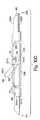
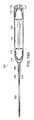
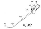
本発明の別の局面では、このシステムは、移植物を患者の身体中の解剖学的部位に送達するための送達アセンブリを含む。1つの実施形態では、この送達アセンブリは、後退ポイント、近位ボタンを含む送達ハンドル、および遠位ボタンを含む。この近位ボタンおよび遠位ボタンは、後退ポイントに作動可能に連結される。近位ボタンおよび遠位ボタンの各々は、この後退ポイントを、第1の位置から第2の位置に移動させる。本発明の1つの実施形態では、この送達アセンブリは、管腔を有するカニューレをさらに含む。このカニューレはアーク(arc)を含み得る。送達アセンブリのこの後退ポイントは、カニューレの管腔中に配置され得る。 In another aspect of the invention, the system includes a delivery assembly for delivering the implant to an anatomical site in the patient's body. In one embodiment, the delivery assembly includes a retract point, a delivery handle including a proximal button, and a distal button. The proximal and distal buttons are operably connected to the retract point. Each of the proximal button and the distal button moves this retract point from the first position to the second position. In one embodiment of the invention, the delivery assembly further includes a cannula having a lumen. The cannula can include an arc. This retraction point of the delivery assembly can be placed in the lumen of the cannula.
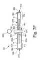
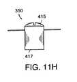
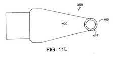
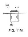
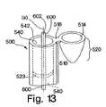
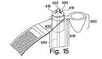
本発明のこの局面のなお別の実施形態では、この送達アセンブリは、送達ハンドルの細長い本体部分上に位置する拡張管(dilator tube)および伸長器ボタン(extender button)をさらに含み得る。この伸長器ボタンは、拡張管に作動可能に連結され、そして送達ハンドルの細長い本体部分の遠位端から、拡張管を伸長および後退させる。拡張管は中空の部材を含む。1つの実施形態では、この中空部材は、この中空部材の壁に取り付けられた剛直なリングをさらに含む。 In yet another embodiment of this aspect of the invention, the delivery assembly may further include a dilator tube and an extender button located on the elongated body portion of the delivery handle. The extender button is operably connected to the expansion tube and extends and retracts the expansion tube from the distal end of the elongated body portion of the delivery handle. The expansion tube includes a hollow member. In one embodiment, the hollow member further includes a rigid ring attached to the wall of the hollow member.
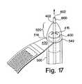
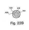
本発明の別の実施形態では、拡張管は円錐形先端部を含む。この円錐形先端部はヒンジを含み、そしてこのヒンジはこの管の壁の一部分であり得る。本発明による1つの実施形態では、取り付け片の第1の部材は、拡張管の管腔内に適合するサイズおよび形状である。第1の部材は、第1の部材と拡張管が一緒に係留されるとき、この拡張管により取り囲まれる第1の部分および第2の部分を含む。本発明の1つの実施形態では、この第1の部材は、スリットを有する第1の端部を含む。1つの実施形態では、第1の部材が拡張管中に係留されるとき、上記付属物は、円錐形先端部とこの管との間に位置する。別の実施形態では、この円錐形先端部は、第1の部材の第1の位置上に着座するようなサイズおよび形状であり、この第1の部材を拡張管に係留する。なお別の実施形態では、第1の部材と拡張管が係合するとき、この第1の部材の第1の部分は、拡張管の管腔から伸長する。円錐形先端部は、送達アセンブリの組織貫通端部に位置し、そしてまたアパーチャを含み得る。このアパーチャは、それを通ってカニューレが出現し得る開口部を提供し得る。 In another embodiment of the invention, the expansion tube includes a conical tip. The conical tip includes a hinge, and the hinge can be a portion of the wall of the tube. In one embodiment according to the present invention, the first member of the attachment piece is sized and shaped to fit within the lumen of the dilation tube. The first member includes a first portion and a second portion that are surrounded by the expansion tube when the first member and the expansion tube are anchored together. In one embodiment of the invention, the first member includes a first end having a slit. In one embodiment, the appendage is located between the conical tip and the tube when the first member is anchored in the expansion tube. In another embodiment, the conical tip is sized and shaped to seat on the first position of the first member and anchors the first member to the expansion tube. In yet another embodiment, when the first member and the expansion tube engage, the first portion of the first member extends from the lumen of the expansion tube. The conical tip is located at the tissue penetrating end of the delivery assembly and may also include an aperture. This aperture may provide an opening through which the cannula can emerge.
別の局面では、本発明は、患者の身体中の解剖学的部位に移植物を配置する方法に関する。この方法では、移植物およびエンベロープを含むシステムが提供される。このエンベロープは移植物を取り囲むように構成され、そしてこのエンベロープの内表面および外表面の少なくとも1つの上に配置される薬物を含む。このシステムは、患者の身体中で、処置されるべき解剖学的部位に挿入される。薬物はエンベロープから放出され、そして患者身体中の解剖学的部位に送達される。この移植物は解剖学的部位に配置され、そしてエンベロープは患者身体から取り除かれる。エンベロープの除去後、移植物は、解剖学的部位においてそれが配置された場所に残る。本発明の方法の1つの実施形態では、移植物は、患者の中央尿道に配置され、例えば、女性の尿失禁を処置する。特定の実施形態では、エンベロープは、エンベロープ外表面上に、または少なくともそれから見える可視指標マークを有し、オペレーターが患者の身体中の解剖学的部位に移植物を配置することを支援する。 In another aspect, the invention relates to a method of placing an implant at an anatomical site in a patient's body. In this method, a system including an implant and an envelope is provided. The envelope is configured to surround the implant and includes a drug disposed on at least one of the inner and outer surfaces of the envelope. The system is inserted into the patient's body at the anatomical site to be treated. The drug is released from the envelope and delivered to an anatomical site in the patient's body. The implant is placed at the anatomical site and the envelope is removed from the patient body. After removal of the envelope, the implant remains where it was placed at the anatomical site. In one embodiment of the method of the present invention, the implant is placed in the central urethra of the patient, for example to treat female urinary incontinence. In certain embodiments, the envelope has visible indicator marks visible on or at least from the outer surface of the envelope to assist the operator in placing the implant at an anatomical site in the patient's body.
外科メッシュのような、移植物を取り囲むエンベロープを、患者身体の損傷した部分に提供することが、本発明の方法のさらなる目的であり、ここで、このエンベロープは、患者身体の内側で外科メッシュの配置の際に、上記損傷した領域に薬物を送達する。この手術メッシュは、例えば、女性患者の中央尿道に適合する形状の三角布またはその他の型のメッシュであり得る。 It is a further object of the method of the present invention to provide an envelope surrounding the implant, such as a surgical mesh, to an injured part of the patient body, where the envelope is the inner side of the surgical mesh inside the patient body. Upon placement, the drug is delivered to the damaged area. The surgical mesh can be, for example, a triangular cloth or other type of mesh shaped to fit the female patient's central urethra.
別の局面では、本発明は、患者の身体中の解剖学的部位に移植物を位置決めする方法を含む。この方法の1つの実施形態では、システムは、移植物を取り囲む少なくとも2つのスリーブを有するエンベロープ、およびこれらスリーブを一緒に連結するクランプを含む。このシステムは、患者の身体中に挿入され、そして処置されるべき解剖学的部位に位置決めされる。一旦、移植物を取り囲むシステムが位置決めされると、クランブがはずされ、そして患者の身体から取り除かれ、患者の身体からスリーブが連結を解かれ、そして除去される。移植物は、患者の身体中で処置されるべき解剖学的部位に位置決めされて残る。 In another aspect, the present invention includes a method of positioning an implant at an anatomical site in a patient's body. In one embodiment of this method, the system includes an envelope having at least two sleeves surrounding the implant and a clamp that connects the sleeves together. The system is inserted into the patient's body and positioned at the anatomical site to be treated. Once the system surrounding the implant is positioned, the crumble is removed and removed from the patient's body, and the sleeve is uncoupled and removed from the patient's body. The implant remains positioned at the anatomical site to be treated in the patient's body.
別の局面では、本発明は、患者の身体中の解剖学的部位に移植物を配置するための方法である。本発明のこの方法によれば、移植物を取り囲むサイズの管腔を有するエンベロープ、およびこのエンベロープの第1の端部および第2の端部の各々に配置されたタブを含むシステムが提供される。オペレーターは、患者の身体中にこのシステムを挿入し、エンベロープの第1の端部および第2の端部に配置されたタブを掴み、身体中に移植物を位置決め、そしてエンベロープを身体から取り除く。1つの実施形態では、このタブは、患者の身体中で移植物を取り囲むエンベロープを配置するための位置決め部材を含む。このエンベロープは、患者の身体中に移植物を位置決めするための可視指標マークまたは位置決めマークを含み得る。 In another aspect, the invention is a method for placing an implant at an anatomical site in a patient's body. In accordance with this method of the present invention, a system is provided that includes an envelope having a lumen sized to enclose the implant and a tab disposed at each of the first and second ends of the envelope. . The operator inserts the system into the patient's body, grabs the tabs located at the first and second ends of the envelope, positions the implant in the body, and removes the envelope from the body. In one embodiment, the tab includes a positioning member for positioning an envelope surrounding the implant in the patient's body. The envelope may include a visual indicator mark or positioning mark for positioning the implant in the patient's body.
別の局面では、本発明は、患者の身体中の解剖学的部位に移植物を送達するための方法である。この方法によれば、オペレーターは移植物を取り付け片に取り付け、そしてこの取り付け片は送達アセンブリに固定される。この取り付け片がエンベロープに予め取り付けられる1つの実施形態では、オペレーターは、この予め取り付けられた取り付け片およびエンベロープを送達アセンブリ上に取り付け、送達システムを形成する。1つの実施形態では、この送達アセンブリは、ハンドル、後退可能ポイント、近位ボタン、および遠位ボタンを含む。あるいは、この送達アセンブリは、拡張管および伸長器ボタンをさらに含む。この後退可能ポイントは、近位ボタンまたは遠位ボタンのいずれかを作動または移動させることにより伸ばされる。1つの実施形態では、送達アセンブリに取り付けられた移植物が送達システムを提供し、そしてこの送達システムが患者の身体中に導入され、そして解剖学的部位に位置決めされる。移植物が送達アセンブリから離脱され、そして送達アセブリが引き抜かれる。別の実施形態では、送達アセンブリが患者の身体中に導入され、次いで移植物が送達アセンブリに取り付けられ、そして解剖学的部位に位置決めされる。その後、移植物が送達アセンブリから離脱され、そして送達アセンブリが患者の身体から引き抜かれる。本発明の別の実施形態では、この方法は、エンベロープの端部におけるタブを掴む工程、およびエンベロープを裂き、移植物から次いで身体からそれを取り除く工程をさらに包含する。 In another aspect, the invention is a method for delivering an implant to an anatomical site in a patient's body. According to this method, the operator attaches the implant to the mounting piece and the mounting piece is secured to the delivery assembly. In one embodiment, where the attachment piece is pre-attached to the envelope, the operator attaches the pre-attached attachment piece and envelope onto the delivery assembly to form a delivery system. In one embodiment, the delivery assembly includes a handle, a retractable point, a proximal button, and a distal button. Alternatively, the delivery assembly further includes an expansion tube and an extender button. This retractable point is extended by actuating or moving either the proximal button or the distal button. In one embodiment, an implant attached to the delivery assembly provides a delivery system, and the delivery system is introduced into the patient's body and positioned at the anatomical site. The implant is withdrawn from the delivery assembly and the delivery assembly is withdrawn. In another embodiment, the delivery assembly is introduced into the patient's body, and then the implant is attached to the delivery assembly and positioned at the anatomical site. Thereafter, the implant is removed from the delivery assembly and the delivery assembly is withdrawn from the patient's body. In another embodiment of the present invention, the method further comprises the steps of grasping a tab at the end of the envelope, and tearing the envelope and then removing it from the implant and then from the body.
本発明の先に記載の目的およびその他の目的、局面、特徴、および利点は、以下の記載から、および特許請求の範囲からより明らかとなる。 The foregoing and other objects, aspects, features and advantages of the present invention will become more apparent from the following description and from the claims.
(説明)
一般的に、本明細書中に記載される本発明は、患者の体内にインプラントを移植するためのシステムである。図1Aを参照すると、1つの局面において、このシステムは、インプラント10、インプラントを包むエンベロープ20、エンベロープ20またはインプラント10を送達アセンブリ650に取り付けるためのアタッチメント部分350、および患者の体内の解剖学的部位にインプラント10を送達するための送達アセンブリ650を備える。1つの実施形態において、この送達アセンブリ650は、送達ハンドル700、拡張チューブ500およびカニューレ600を有する。(Explanation)
In general, the invention described herein is a system for implanting an implant in a patient's body. Referring to FIG. 1A, in one aspect, the system includes an
1つの局面において、本発明は、インプラントを包むためのエンベロープに関する。このエンベロープは、エンベロープの外部表面上、内部表面上、または外部表面および内部表面の両方上に、治療薬物(例えば、抗生物質)を含む。 In one aspect, the present invention relates to an envelope for wrapping an implant. The envelope contains a therapeutic drug (eg, an antibiotic) on the outer surface, the inner surface, or both the outer and inner surfaces of the envelope.
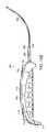
図1Bに図示される本発明の1つの実施形態において、このシステムは、エンベロープ20で囲まれるかまたはエンベロープ20中に包まれたインプラント10(例えば、外科的メッシュまたは外科的スリング)を備える。このエンベロープ20は、メッシュ10を囲むポーチまたはスリーブに例えられ得る。 In one embodiment of the invention illustrated in FIG. 1B, the system comprises an implant 10 (eg, a surgical mesh or surgical sling) that is enclosed in or encased in an
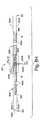
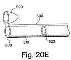
図1Cを参照すると、1つの実施形態において、エンベロープ20は、内腔185を有し、そしてこのエンベロープ20は、例えば、メッシュ10を包むチューブである。このエンベロープ20は、内部表面30および外部表面40を有する。図1Cを参照すると、エンベロープ20の幅24は、エンベロープ20の第1側面203と第2側面204との間で測定される場合、約0.2インチ〜約2.0インチの範囲を有し得、好ましくは約0.5インチと約0.8インチとの間であり、そして最も好ましくは、0.6インチである。エンベロープ20の長手軸22は、エンベロープ20の第1末端201から第2末端202まで測定すると、約3.9インチ〜約27.6インチの範囲であり、好ましくは約11.8インチと約23.6インチとの間であり、最も好ましくは、19.7インチである。1つの実施形態において、第1末端201および第2末端202は開口している。あるいは、第1末端201および第2末端202は、例えば、熱シール接着によって閉じられ得る。 Referring to FIG. 1C, in one embodiment, the
本発明に従う1つの実施形態において、インプラントは外科的メッシュ10である。この外科的メッシュ10は、1本以上の編み糸から作られ得、そして編み糸は、1つ以上の物質から作製され得る。使用され得る非限定的な物質としては、米国特許第6,042,592号(この開示は本明細書中で参考として援用される)に記載されるように、ポリプロピレン、ポリエステル、ポリオレフィン、ポリテトラフルオロエチレン、ポリエチレン、ポリウレタン、ナイロンおよびそれらのコポリマーが挙げられる。この外科的メッシュ10は、合成物質および組織のハイブリッドであり得る;このインプラント10は、例えば、U.S.S.N.09/916,983号(この開示全体が本明細書中で参考として援用される)に記載されるスリングに関し得る。この外科的メッシュ10はまた、吸収性の物質(例えば、ポリグリコール酸、ポリ乳酸および他の適切な吸収性の物質)が適し得る。 In one embodiment according to the present invention, the implant is a
編み糸は、複数の繊維を含み得るか、あるいは単一繊維の編み糸が使用され得る。1つの実施形態において、このメッシュは、外科的適用における使用のためのポリプロピレン単一繊維のトリコットメッシュである。メッシュ10の中に、各編み糸は編み糸繊維の間に空隙領域を有し得る。このメッシュ10を作るために使用されるプロセスは、このメッシュ10中に間隙を形成し得る。多繊維の編み糸は、編み糸繊維の間に複数の空隙または介在空間を有する。本発明に従って、メッシュ10は、編物、織物また編組(braiding)を含む(が、これらに限定されない)、当業者に公知の種々の製造プロセスに従って作製され得る。多繊維の編み糸を使用して作られたメッシュは、間隙および内部空隙の両方を有し得る。本発明に従う1つの実施形態において、外科的メッシュ10は、この外科的メッシュ10を取り囲むエンベロープ20の中に包まれる。このメッシュ10を取り囲むエンベロープ20は、者の体内の解剖学的部位にメッシュを設置する手順の間に、このメッシュ10が患細菌のような外来物質で汚染される可能性を低減させる。 The knitting yarn may include a plurality of fibers, or a single fiber knitting yarn may be used. In one embodiment, the mesh is a polypropylene monofilament tricot mesh for use in surgical applications. Within the
図1Bおよび図1Cを続けて参照すると、本発明に従う1つの実施形態において、インプラント10はスリングであり、例えば、Gellmanらによる、「Medical Slings」と表題が付けられた米国特許出願(代理人事件整理番号(BSC−205)、この本願と共に出願され、その開示全体が本明細書により全て参考として援用される)に記載されたスリング10である。 With continued reference to FIGS. 1B and 1C, in one embodiment according to the present invention, the
スリング10の長手軸13は、約3.9インチ〜約24.0インチの範囲であり得るか、または約15.7インチ〜約19.7インチの間であり得、好ましくは約17.7インチであり得る。このスリング10の幅14は、約0.39インチと約1インチとの間であり、好ましくは約0.43インチである。図1Cをなお参照すると、このスリング10の厚さ15は、約0.0025インチと約0.1インチとの間の範囲であり、好ましくは約0.001インチと約0.01インチとの間である。 The
図1Bおよび図1Cをなお参照すると、エンベロープ20を作成するために使用される物質の厚さは、約0.0001インチ〜約0.01インチの範囲であり得、好ましくは0.0003インチの厚さである。図1Cに示されるように、このエンベロープは第1側面21および第1側面21の反対側の第2側面23を有する。エンベロープ20の第1側面21と第2側面23との間の距離は、約0.0027インチ〜約0.12インチの間の範囲である。 Still referring to FIGS. 1B and 1C, the thickness of the material used to make the
エンベロープ20は、外科的な設置の間、スリング10を操作することを補助するために、および/またはスリング10を調節することを補助するために使用され得る。例えば、このエンベロープ20は、患者の体内の解剖学的部位でのスリング10の設置前のスリング10の操作に起因して、スリング10が伸張することまたは歪みを生じることから防ぐことを補助する。 The
1つの局面において、本発明は、薬物送達特性を有するインプラント10を送達するためのシステムを提供する。この薬物は、患者の体内の解剖学的部位に送達され、そして医者の選択に従って選択され得る。好ましくは、例示的薬物は、水または他の生物学的に不活性な溶液に可溶であり、そして、抗菌物質および抗生物質(例えば、ネオマイシンおよびサルファ剤)、ならびに抗炎症剤(例えば、ステロイド性または非ステロイド性の抗炎症剤)が挙げられるが、これらに限定されない。この薬物は、患者の組織との接触の際にその組織に対して放出される。従って、エンベロープ20を利用して挿入する場合に患者の組織表面に送達される薬物は、インプラントの移植の間の患者組織との接触の際、活性である。 In one aspect, the present invention provides a system for delivering an
例えば、図1Bおよび図1Cを再度参照すると、本発明に従う1つの実施形態において、薬物送達システムは、例えば、スポンジ様物質のような、1つ以上の吸収性物質から作製されるエンベロープ20を備える。このエンベロープ20は、患者の体内へのインプラント10の外科的移植の前に、抗生物質のような薬物を含む溶液中に予め浸漬され得る。手術直前に薬物を含む溶液中にエンベロープ20を浸漬することにより、このエンベロープ20の外部表面40がその薬物でコーティングされる。薬物溶液中にエンベロープを予め浸漬することは好都合である。なぜなら、エンベロープ20がインプラント10の外科的な移植の間に患者の体内に挿入される場合、患者の体組織の内部は、薬物でコーティングされたエンベロープ20で拭われるからである。あるいは、このエンベロープが浸漬される薬物溶液中の薬物は、吸収性物質に浸透して、そして吸収性エンベロープ20の内部表面30をコーティングする。 For example, referring again to FIGS. 1B and 1C, in one embodiment according to the present invention, the drug delivery system comprises an
別の実施形態において、本発明に従って、エンベロープ20は、ポリプロピレン、ポリエチレン、ポリエステル、ポリテトラフルオロエチレン、TYVEK(登録商標)、MYLAR(登録商標)、またはそれらのコポリマーのような、非湿潤性の物質から作製される。ポリテトラフルオロエチレンは、本発明に従う使用に適しており、そしてDuPont(Wilmington、Delaware、商品名TEFLON(登録商標)の下で)より入手可能である。これらの非湿潤性物質は、液体、例えば薬物溶液を全く取り込まない。これらの非湿潤性物質の表面に対する薬物の結合または吸収を可能にするために、このエンベロープ20の内部表面30および/または外部表面40は、例えば湿潤性のコーティング組成物のような湿潤性である物質で前処理される。この湿潤性コーティング組成物は、例えば、ポリビニルピロリドン(PVP)のような合成コーティング、または例えばコラーゲンのような天然のコーティングであり得る。このコーティングは、例えばセルローススポンジ物質のような物理学的に吸収性の物質であり得る。この湿潤性コーティング組成物は親水性であり得、これは親水性の薬物を吸収する。1つの実施形態において、この親水性薬物は、親水性のコーティングと結合する。あるいは、疎水性の薬物がエンベロープ20上に配置されて、このエンベロープ20は疎水性コーティングを含む。いくつかの実施形態において、疎水性コーティングは、エンベロープ表面に疎水性の薬物をトラップする。 In another embodiment, in accordance with the present invention, the
本発明に従う別の実施形態において、親水性のコーティングは、エンベロープ20の1つ以上の表面に適用され得る。この疎水性コーティングは、疎水性薬物と組み合わせて使用され得る。エンベロープ20の疎水性コーティングと薬物との間の結合が弱い場合、この薬物は、エンベロープ20によって接触される組織表面に対して容易に放出される。あるいは、コーティングと薬物との間のより強力な結合(すなわち、より強力な結合親和性)は、この薬物のより遅滞した放出を提供し得る。 In another embodiment according to the present invention, a hydrophilic coating may be applied to one or more surfaces of
本発明に従う特定の実施形態において、エンベロープ20の表面に適用されるコーティングは、イオン性の電荷を有し得る。本発明のこの実施形態に従って、コーティングおよび薬物がお互いに曝される場合、相補的な電荷を有する薬物は、エンベロープ20の表面に適用された荷電したコーティングと結合する。薬物とコーティングとの間の結合の強度は、この薬物がエンベロープ20の表面からどれほど容易に放出されるかということに影響する。エンベロープ20上のコーティングと薬物との間のイオン性の結合が弱い場合、この薬物はより容易に放出される。エンベロープ20の表面コーティングと薬物との間の共有結合は、薬物放出を減少させる。 In certain embodiments according to the present invention, the coating applied to the surface of the
例えば図2Bに示される、本発明に従う1つの実施形態において、エンベロープ20の内部表面30は内部表面コーティング35を有し、そしてエンベロープ20の外部表面40は外部表面コーティング45を有する。内部表面コーティング35および外部表面コーティング45は、合成および天然のコーティングから選択され得る。合成または天然のコーティングは、親水性剤、疎水性剤、および物理学的に吸収性の物質(例えば、セルローススポンジ状物質)からなる群より選択され得る。 In one embodiment in accordance with the present invention, for example shown in FIG. 2B, the
本発明の特定の実施形態において、エンベロープ20の一方の表面のみがコーティングされる。例えば、エンベロープ20の内部表面30のみがコーティングされる。あるいは、別の実施形態において、エンベロープ20の外部表面40がコーティングされる。コーティングされた表面を有するエンベロープ20は、手術直前に、薬物(例えば、親水性薬物)を含む溶液中に浸漬され得る。溶液中の薬物は、エンベロープ20上の親水性コーティングと結合する。別の実施形態において、親水性コーティングおよび親水性薬物を混合して、単一なコーティングを形成する。この親水性コーティングは、エンベロープ20の外部表面40、内部表面30、または外部表面40および内部表面30の両方の上に配置され得る。1つの実施形態において、エンベロープは、予め取り込まれた薬物、または薬物およびコーティングの混合物を含む。なお別の実施形態において、エンベロープ20はコーティングされないが、手術直前に薬物溶液中に浸漬される場合、その薬物はエンベロープ20の表面を覆い、そして/または十分な量の薬物(例えば、約0.5ml〜約3mlの間)がエンベロープ20中にトラップされる。 In certain embodiments of the invention, only one surface of the
図2Aおよび図2Bを再度参照すると、本発明の1つの実施形態において、エンベロープ20の内部表面コーティング35は疎水性であり得る。別の実施形態において、この疎水性コーティングは、これもまた疎水性である薬物と混合される。その後、予め混合された疎水性コーティングおよび疎水性薬物の組み合わせ混合物は、エンベロープ20の内部表面30上に配置される。図2Bは、図2Aに図示されるインプラント10を備えるシステムの実施形態の断面図である。図2Bは、内部表面コーティング35が、エンベロープ20の第1側面21の内部表面30および第2側面23の内部表面30上に配置されることを図示する。別の実施形態において、薬物およびコーティングの組み合わせが、その上に配置し得る。 Referring again to FIGS. 2A and 2B, in one embodiment of the present invention, the
代替の実施形態において(示さず)、エンベロープ20の外部表面40は、疎水性コーティングおよび疎水性薬物の組み合わせ混合物でコーティングされる。 In an alternative embodiment (not shown), the
親水性コーティングは水溶性であり得、そして適切な水溶性親水性コーティングは、Boston Scientific Corp.、Natick、MAから、商品名HydroPlusおよびHydroPassの下で入手可能である。ヒオスシアミン(hyoscymine)硫酸塩は、本発明に従って使用され得、これはPolymedica(Woburn、MA)から、商品名CYTOSPAZの下で入手可能である。ケトロラックトロメタミン(ketrolac tromethamine)は、Roche Pharmaceuticals(Nutley、NJ)より商品名Toradolの下で入手可能である。本発明に従って使用され得る親水性薬物としては、オキシブチニンクロライド、リドカイン、ケトロラックおよびヒオスシアミン硫酸塩が挙げられる。適切な疎水性薬物としては、イブプロフェン、ケトプロフェンおよびジクロフェナクが挙げられる。本発明に従って使用され得る疎水性コーティングとしては、ポリテトラフルオロエチレン、シリコンおよびピレレン(pyrelene)が挙げられる。 Hydrophilic coatings can be water soluble, and suitable water soluble hydrophilic coatings are available from Boston Scientific Corp. , Natick, MA, available under the trade names HydroPlus and HydroPass. Hyoscymine sulfate can be used in accordance with the present invention, which is available from Polymedica (Woburn, Mass.) Under the trade name CYTOSPAZ. Ketorolac tromethamine is available from Roche Pharmaceuticals (Nutley, NJ) under the trade name Toradol. Hydrophilic drugs that can be used in accordance with the present invention include oxybutynin chloride, lidocaine, ketorolac and hyoscyamine sulfate. Suitable hydrophobic drugs include ibuprofen, ketoprofen and diclofenac. Hydrophobic coatings that can be used in accordance with the present invention include polytetrafluoroethylene, silicon, and pyrylene.
本発明に従う、図3Aおよび図3Bに図示される別の実施形態において、1つ以上のアパーチャ50が、エンベロープ20中に導入される。このアパーチャ50は、例えば、切れ目またはスリットであり得る。これらのアパーチャ50はエンベロープ20を通って延びて、そしてエンベロープ20の少なくとも第1側面21を通って配置される。別の実施形態において、これらのアパーチャ50は、エンベロープ20の全ての側面に導入される。これらのアパーチャ50は、エンベロープ20の内部表面30への薬物の接近を可能とする。例えば、エンベロープ20が薬物を含む溶液中に浸漬される場合、この薬物はアパーチャ50を介してエンベロープ20の内腔185に入り込み、そして内部表面コーティング35と会合する。 In another embodiment illustrated in FIGS. 3A and 3B in accordance with the present invention, one or
図3Aおよび図3Bをなお参照すると、本発明に従う別の実施形態において、エンベロープ20の外部表面40および内部表面30は、イオン性のコーティング組成物でコーティングされる。あるいは、エンベロープ20の外部表面40または内部表面30のうちの一方のみが、イオン性コーティング組成物でコーティングされる。アパーチャ50を有するエンベロープ20が、イオン性コーティング組成物の電荷に相補的な電荷を保持する薬物を含む溶液中に浸漬される場合、外部表面コーティング45および内部表面コーティング35の両方がその薬物と結合する。図3Bは、1つの実施形態において、エンベロープ20の第1側面21の内部表面30が、内部コーティング表面35を含み、そして第1側面21の外部表面40が外部表面コーティング45を含むことを示す。同様に、図3Bはまた、エンベロープ20の第2側面23の内部表面30が内部表面コーティング35を含み、そして第2側面23の外部表面40が外部表面コーティング45を含むことを示す。 Still referring to FIGS. 3A and 3B, in another embodiment according to the present invention, the
図3Aおよび図3Bに示される、本発明の1つの実施形態において、アパーチャ50は、エンベロープ20の少なくとも第1側面21上に存在する。この実施形態において、薬物は、アパーチャ50を通ってエンベロープ20の内腔185中へと流れる場合に、エンベロープ20の内部表面30と接触する。この薬物は内部表面コーティング35と会合する。特定の実施形態において、外部表面コーティング45は、例えばエンベロープ20が薬物を含む溶液中に浸される場合、薬物と結合する。 In one embodiment of the invention shown in FIGS. 3A and 3B, the
エンベロープ20上に配置される1つ以上のアパーチャ50は、例えば、エンベロープ20を通って配置されるスリットである。これらのアパーチャ50はエンベロープ20中に配置され、エンベロープ20の内腔185に薬物が入り、そしてエンベロープ20の内部表面30と接触することを可能にするために、エンベロープ20上に開口部を提供する。1つの実施形態において、これらのアパーチャ50は、約1/16インチ〜最大寸法で約1/4インチのサイズの範囲であり、そしてエンベロープ20の内腔185の内外の液体交換を可能にする。1つの実施形態において、エンベロープ20を製造するために使用される物質は、多孔性の物質、例えば、ポリテトラフルオロエチレン物質またはポリエチレン物質であり、そして孔が約1ミクロン以上に達するように引き延ばされ得る。 The one or
1つの実施形態において、1つ以上のアパーチャ50は、溶液がエンベロープ20の内腔185に流入することを許容するが流出は許容しないように配置され得る(すなわち、一方向チャネル)。別の実施形態において、エンベロープ20を通って配置される1つ以上のアパーチャ50は、孔またはスリットであり得る。このようなアパーチャ50は、約1ミクロン〜最大寸法で約1/4インチの大きさの範囲であり得る。例えば、約1/16インチと最大寸法で1/4インチとの間の比較的大きなアパーチャ50は、エンベロープ20が薬物を含む溶液中で浸漬される場合、薬物を含む溶液がエンベロープ20の内部表面30の中へと容易に侵入し、そしてそこと接触することを可能とする。いくらかの溶液はまた、エンベロープ20から免れる。別の実施形態において、1つ以上のアパーチャ50は、非常に小さい(すなわち、約5ミクロン)ために、その溶液がエンベロープ20から逃れることを許容しない。 In one embodiment, one or
図3Aおよび図3Bに示されるように、本発明に従う別の実施形態において、エンベロープ20はまた、裂け目60を含む。裂け目60は、患者の体内でエンベロープ20によって取り囲まれたメッシュ10の配置のためにエンベロープ20を開ける際に、操作者を補助する。この裂け目60は、エンベロープ20を通る一連の穿孔であり得る。このエンベロープ20を通る一連の穿孔は、裂け目が配列されたエンベロープ20の一部を弱め、その結果、裂け目60は、操作者がエンベロープ20に最小の力を適用することによってエンベロープ20を開けることを可能にする。特定の実施形態において、この裂け目60は、エンベロープ20の周囲ほぼ全体に配置される。あるいは、この裂け目60は、単にエンベロープ20の周囲の一部に沿って配置され得る。 As shown in FIGS. 3A and 3B, in another embodiment according to the present invention, the
本発明のさらに別の実施形態において、裂け目60の穿孔は、隙間50の2倍であり得、これはエンベロープ20の浸されている溶液が、エンベロープ20の管腔185に入ることを可能にし、そして、エンベロープ20の内面30と接触することを可能にする。例えば、裂け目60がエンベロープ20を通る一連の隙間50であり、エンベロープ20が薬物溶液に浸されている場合、この隙間50は、薬物溶液が被20の内面30に接触するために、エンベロープ20を通って管腔185に穿孔することを可能にする。 In yet another embodiment of the present invention, the perforation of the
あるいは、裂け目60は、容易に引き裂き得る材料を含有する。このような引き裂きの容易な材料として、例えば、低密度ポリエチレンまたは線状ポリテトラフルオロエチレン(例えば、TEFLON(登録商標))のような分子配向を有する材料が挙げられるが、これらに限定されない。あるいは、エンベロープ20の1つ以上の部分のみが、「引き裂き可能な」材料および/または構築方法、すなわち線状低密度ポリエチレンおよび/またはエンベロープの領域に渡る一連の穿孔もしくは隙間50を含むセクションから製造される。本発明に従う別の実施形態において、裂け目60はまた、以下に基づき、図8A〜8Kおよび9A〜9Eに詳細に記載されるように、引き裂かれ得るタブ188およびタブ198を備えるエンベロープ20を含む。さらに別の実施形態において、裂け目60は、エンベロープ20の幅24の周囲全体について配置された材料の小片である。この材料の小片は、例えば、エンベロープの内面30に位置付けられ得る。この材料の小片は、エンベロープ20の1つ以上の領域から突き出て、これがアクセスされ得、そして引き裂かれ得る場合、エンベロープ20の周囲の少なくとも一部に解体する。 Alternatively, the
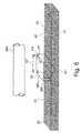
本発明のさらに別の実施形態において、このエンベロープは、2つ以上の材料の複合物である。ここで、図4A、4Bおよび4Cを参照して、エンベロープ20の第1の側面21は、第1の材料を含有し、そしてエンベロープ20の第2の側面23は、第1の材料とは異なる第2の材料を含有する。図4Cはエンベロープ20の側面図を描き、ここで、第1の側面21は第1の材料を含有し、第2の側面23は第2の材料を含有し、そして側面21および23は、エンベロープ20を形成するために縫い目27に並べられそして結合される。 In yet another embodiment of the invention, the envelope is a composite of two or more materials. Referring now to FIGS. 4A, 4B, and 4C, the
1つの実施形態において、エンベロープ20の第1の側面21の第1の材料は、引き裂き可能な材料からなる群より選択され、これらの材料として、例えば、ポリプロピレン、ナイロン、線状低密度ポリプロピレンのような分子配向性を有する材料あるいは他の利用可能な可撓性のフィルムが挙げられる。別の実施形態において、エンベロープ20の第2の側面23の第2の材料は、引き裂かれない材料であり得、例えば、ポリテトラフルオロエチレン、TYVEK(登録商標)、MYLAR(登録商標)または例えば、熱可塑性のような他の材料であり得る。本発明に従う、複合エンベロープ20は、引き裂かれない2つの異なる材料から形成され得る(例えば、第1の側面21は、TYVEK(登録商標)を有し、そして第2の側面23は、MYLAR(登録商標)を有する)。あるいは、複合エンベロープ20は、ポリエチレンの第1の側面21およびポリプロピレンの第2の側面23といった、裂ける2つの材料から形成され得る。 In one embodiment, the first material of the
図4Aは、図4Cに図示されたエンベロープ20の第1の側面21を図示し、そして図4Bは、図4Cに図示されたエンベロープ20の第2の側面23を図示する。図4Aを再び参照して、上面931から下面941までを測定した第1の側面21の幅241は、約0.2インチ〜約2.0インチにわたるか、または約0.5インチ〜約0.8インチにわたり、そして好ましくは、0.6インチである。図4Aに図示されるように、第1の端部911から第2の端部921までを測定した第1の側面21の長手方向軸221は、約3.9インチ〜約27.6インチの長さにわたるか、または約11.8インチと約23.6インチとの間であり、好ましくは、19.7インチである。図4Bを再び参照して、上面932から下面942までを測定した、第2の側面23の幅242は、約0.2インチ〜約2.0インチにわたるか、または約0.5インチと約0.8インチとの間であり、好ましくは0.6インチである。第1の端部912から第2の端部922までを測定した、第2の側面23の長手方向軸222は、約3.9インチ〜約27.6インチにわたるか、または約11.8インチと約23.6インチとの間であり、好ましくは19.7インチである。 4A illustrates a
図4A、4Bおよび4Cを再び参照して、1つの実施形態において、エンベロープ20の第1の側面21および第2の側面23は、大きさに切断され得、そして第1の側面21は、第2の側面23の上端に配置され得そして、第2の側面23に並べられ得る。第1の側面21および第2の側面23が並べられる場合、第1の側面21の上面931および第2の側面23の上面932は隣接し(示さず)、第1の側面21の下面941および第2の側面23の下面942は、隣接し、第1の側面21の第1の端部911および第2の側面23の第1の端部912は隣接し、そして第1の側面21の第2の端部921および第2の側面23の第2の端部922は隣接する。エンベロープ20は、例えば、並べた第1の側面21および第2の側面23の周辺を熱接着することにより形成され得、並べた第1の側面21および第2の側面23の4つの側面の周囲に縫い目27を形成し得る。さらに図4Cを参照して、別の実施形態において、管状エンベロープ20を形成するために、第1の縫い目(示さず)は、第1の側面21の上面931と第2の側面23の上面932との間に形成され、そして第2の縫い目27は、第1の側面21の下面941と第2の側面23の下面942との間に形成され、従って、エンベロープ20の内部は、第1の開口端201および第2の開口端202とを備える管腔185を備える。 Referring again to FIGS. 4A, 4B, and 4C, in one embodiment, the
あるいは、第1の側面21が、第2の側面23の上端に配置される場合、第2の側面23(これは、第1の側面21に隣接する)は、融解性ライナー(melt liner)を含み得る。融解性ライナーは、第1の側面21および/または第2の側面23に加えられる場合(例えば、側面21および側面23が、所望の温度範囲に曝される場合)、第1の側面21と第2の側面23との間の縫い目27の形成を補助する、層または層の一部である。使用され得る適切な融解性ライナーとしては、例えば、低密度ポリエチレン、ポリウレタン、およびポリエステルが挙げられる。1つの実施形態において、第2の側面23は、引き裂かれ得ない材料(例えば、TYVEK(登録商標))を含む。1つの実施形態において、第1の側面21に隣接するTYVEK(登録商標)の少なくとも側面は、融解性ライナーに覆われ、この融解性ライナーは、エンベロープ20の縫い目27を形成するために第1の側面21と第2の側面23とを熱シールすることが可能である。図4Cに示される、エンベロープ20のさらに別の実施形態において、第1の側面21および第2の側面23は、縫い目27を形成するために接着剤を用いて結合される。適切な接着剤として、例えば、ウレタンベースの接着剤およびポリエステルベースの(すなわちエラストマーの)接着剤が挙げられる。1つの実施形態において、縫い目27は、複合エンベロープ20の引き裂き可能な領域を形成する。図4Dおよび図4Eに図示される別の実施形態において、第2の側面23は、第1の側面21より寸法が大きい。1つの実施形態において、第2の側面23の幅242の寸法を測定すると約0.8インチであり、そして第2の側面23の長手方向軸222を測定すると、約27.6インチである。第1の側面21の幅241の寸法を測定すると、約0.5インチであり、長手方向軸221を測定すると、約27インチである。第1の側面21は、上端面21aおよび底面21b(示さず)を有し、そして第1の側面21は、第2の側面23の上端に配置される。別の実施形態において、第1の側面21は、第2の側面23の中央に配置される。第2の側面23は、上端面23aおよび底面23bを有する。 Alternatively, if the
図4Eおよび4Fは、図4Dに示される第2の側面23の幅242に沿う余剰資材をが、第1の側面21の上端部21aに位置するように折り畳まれることを示す。第2の側面23の上面932の折り畳まれた部分26は、第1の縫い目27を形成するために第1の側面21の上端面21aと結合され、そして第2の側面23の底面942の折り畳まれた部分26はまた、第2の縫い目27を形成するために、第1の側面21の上端面21aと結合される。第1の側面21の上端面21aに折り畳まれた第2の側面23の折り畳まれた部分26は、接着剤を含み、この部分は、第2の側面23の上端面23aを第1の側面21の上端面21aに結合し、管腔185を有するエンベロープ20を形成する。あるいは、第2の側面23の上端面23a(これは、第1の側面21の上端面21aに隣接する)は、融解性ライナーを含む。第2の側面23の一部が、第1の側面21を超えて折り畳まれる場合、融解性ライナーは、例えば、折り畳まれた部分26に熱を与えることによって、第2の側面23の折り畳まれた部分26と第1の側面21とを連結し、第2の側面23と第1の側面21の上端面21aとを結合し、縫い目27を形成する。さらに別の実施形態において、第1の側面21の第1の材料および第2の側面23の第2の材料は、折り畳まれた部分26において熱接着により結合され、縫い目27を形成する。 4E and 4F show that the surplus material along the
特定の実施形態において、図4Dおよび図4Eを再び参照して、第1の側面21の第1の材料は、引き裂き可能(すなわち、線状低密度ポリエチレン)であり、そして第2の側面23の第2の材料は、引き裂かれ得ない(例えば、MYLAR(登録商標))。ここで、図4Eおよび4Fを参照して、第2の側面23の上端面23aの折り畳まれた部分26は、上面932で、第1の側面21の上端面21aと結合され、第1の縫い目27を形成し、そして第2の側面23の下面942は、第2の縫い目27を形成する。一旦、第1と第2の縫い目27が形成されると、第1の側面21および第2の側面23は、エンベロープ20を形成し、このエンベロープ20は、管腔185を有する。管腔185の第1の側面21の第1の端部911が、第2の端部921に向かって引き抜かれる場合、折り畳まれた部分26での第2の側面23のほぼ上面932および下面942とで結合された第1の側面21の引き裂き可能な材料は、縫い目27で引き裂かれ、そして第2の側面23から切り離される。従って、引き裂き可能な領域は、引き裂かれない材料が、引き裂かれる材料と結合されているエンベロープの領域を含み得る。 In certain embodiments, referring again to FIGS. 4D and 4E, the first material of the
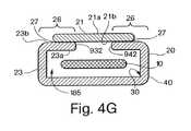
図4Gは、ここで、第1の側面21の底面21bが、ほぼ折り畳まれた部分26で第2の側面23の底面23bと結合され、エンベロープ20の第1の縫い目27および第2の縫い目27を形成するための実施形態を図示する。1つの実施形態において、第1の側面21上の第1の材料が引き裂き可能ではなく、そして第2の側面23上の第2の材料が、引き裂き可能であり、第1の側面21が第2の側面23から分離される場合、第2の側面23は、縫い目27で引き裂かれる。 FIG. 4G shows that the
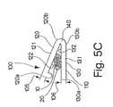
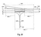
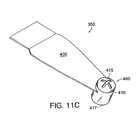
別の実施形態において、ここで図5A〜5Eを参照して、本発明は、スペーサー100を備えるエンベロープ20、インプラント10を取り囲むエンベロープ20を特徴とする。スペーサー100は、エンベロープ20の少なくとも1つの外部面上の突出部であり、患者の体内における解剖学的部位にてインプラント10の位置決めを補助するための、1つ以上の事前に選択された平面を備える。図5Aに図示される1つの実施形態において、エンベロープ20は、中間尿道スリング(mid−urethral sling)10のようなインプラント10を取り囲む。スペーサー100は、患者の身体の内部へのスリング10の配置を調整するために使用される。例えば、スリング10が、アンカーを有さない中間尿道スリング安定化法により、腹圧性尿失禁の処置のために使用される場合、事前に選択された寸法を備えるスペーサー100は、スリング10および患者の尿道999を取り囲むエンベロープ20との間の距離の参照を提供するために使用される。操作者は、スペーサー100の既知の事前に選択された寸法によって、スリング10を封入するエンベロープ20と患者の尿道999との間の相対距離を参照され得る。操作者はまた、スペーサー100に適用される張力に関して、スリング10を調整し得る。1つの実施形態において、裂け目60を含むエンベロープ20はまた、図3A〜3Bに関連して記載されたような、スペーサー100を備え、このスペーサーは、張力の調整を提供し得る。裂け目60は、スリング10が配置された後の、エンベロープ20の除去を単純化する。 In another embodiment, referring now to FIGS. 5A-5E, the present invention features an
本発明に従う1つの実施形態において、図5Aに図示されるスペーサー100は、エンベロープ20の周辺に固定される。図5Bおよび5Cにおいて図示される1つの実施形態において、スペーサー100は、エンベロープ20の周辺で固定され得るクランプ110である。クランプ110スペーサー100は、エンベロープ20に開放可能なように結合され得る。クランプ110は、第1の部材120および第2の部材130を有する。第1の部材120は、近位端120aおよび遠位端120b、ならびにそれらの間に広がる少なくとも第1の外部面121および第1の厚み105を有する。クランプ110はまた、第1の内部面122を有する。第2の部材130は、近位端130aおよび遠位端130b、ならびにそれらの間に広がる少なくとも第2の外部面131および第2の厚み106を有する。1つの実施形態において、(示さず)、第1の部材120の近位端120aおよび第2の部材130の近位端130aは、例えば結合することによって、係合可能であり、そして第1の部材120の遠位端120bおよび第2の部材130の遠位端130bは、結合することによって係合可能である。 In one embodiment according to the present invention, the
図5Bおよび5Cに示されるような、特定の実施形態において、クランプ110は、さらにヒンジ140を備える。クランプ110のヒンジ140は、第1の部材120とクランプ110の第2の部材130とを連結する。第1の部材120の近位端120aおよび第2の部材130の近位端130aは、舌部および溝型、ネジおよび孔、または当業者に公知の結合のための他の機構のような結合機構によって結合する。クランプ110は、エンベロープ20を取り囲むような大きさにされる。クランプ110の第1部材120の第1の内部面122の長さ、および、クランプ110の第2の部材130の第2の内部面132の長さは、約0.2インチ〜2.0インチにわたる。クランプ110の内部面122の寸法およびクランプ110の内部面132は、エンベロープ20の寸法に従って選択される。 In certain embodiments, as shown in FIGS. 5B and 5C, the
ここで、図5Dを参照して、第1の部材120の幅125およびクランプ110の第2の部材130の幅(示さず)は、約0.2インチと約0.8インチとの間にわたり得、好ましくは、約0.4インチと約0.6インチとの間にわたり得る。クランプ110の第1の部材120の長さ127は、約0.2インチ〜約2.0インチの間にわたり得る。図5Bおよび図5Cを再び参照して、クランプ110の第1部材120の厚み105は、約0.007インチと約0.12インチとの間にわたり得る。 Referring now to FIG. 5D, the
1つの実施形態において、さらに図5Aおよび5Bを参照して、スペーサー100は、第1の部材120を備える。スペーサー100の第1の部材120の厚み105は、スリング10を取り囲むエンベロープ20と患者の尿道999または患者の膀胱頚部との間の距離に固定される。第1の部材120がスペーサーである場合、スペーサー100の厚み105の寸法を測定すると、約0.007インチと約0.8インチとの間であり、好ましくは、約0.2インチと約0.6インチとの間である。スペーサー100が、患者の尿道999に隣接して配置される実施形態において、第1の部材120の長さは、第1の部材120の近位端120aおよび遠位端120bとの間の距離によって測定され、患者の尿道999の長さを補完する長さに合わされ得、概して、約0.2インチと約1.2インチとの間である。 In one embodiment, with further reference to FIGS. 5A and 5B, the
図5Eに図示される実施形態に示されるように、スペーサー100は、エンベロープ20の第1の側面21に配置されるバルク材112を備え得る。このバルク材112は、例えば、ポリエチレンまたはカルボキシメチルセルロースナトリウムのようなヒドロゲル、リン酸緩衝化生理食塩水(PBS)またはそれらの組み合わせであり得る。1つの実施形態において、バルク材112は、エンベロープ20の第1の側面21の表面全体に配置され得る。 As shown in the embodiment illustrated in FIG. 5E, the
あるいは、図5Eに示されるように、バルク材112は、エンベロープ20の第1の側面21の一部にのみ配置され得る。例えば、1つの実施形態において、バルク材112は、エンベロープ20の第1の側面21の長手方向軸の第1の端部201と第2の端部202との間の中間点に配置され得る。このバルク材112は、長手方向軸の中間点の側面の各々に、約0.1インチ〜約0.4インチの間に配置され得、好ましくは、約0.2インチ〜約0.3インチの間に配置され得る。図5Eの参照を続けて、スペーサー100のバルク材112は、エンベロープ20の第1の側面21の幅24を横切って、すなわちエンベロープ20の上端面203および底面204との間に、配置され得る。図5Aを再び参照して、スリング10を取り囲むエンベロープ20が、アンカーを有さない中間尿道スリング安定化法により、腹圧性尿失禁の処置のために使用される場合、エンベロープ20の幅24は、尿道999または膀胱頚部に隣接する。スペーサー100は、エンベロープ20と患者の尿道999または患者の膀胱頚部との間の距離の参照を提供する。バルク材112は、エンベロープ20の幅24に沿っておよそ、約0.2インチ〜約1.2インチの間に配置されるべきである。なぜならば、スペーサー100は、女性の尿道の長さ以下であるべきだからであり、そして概して、女性の尿道の最大長は、1.2インチである。第1の側面21の上に配置されるバルク材112の厚み103は、約0.007インチ〜約0.8インチの間にわたり得、好ましくは、約0.2インチ〜約0.6インチの間である。 Alternatively, as shown in FIG. 5E, the
図5F〜5Gに図示されるさらに別の実施形態において、スペーサー100は、バルーン111を備える。1つの実施形態において、バルーン111は、エンベロープ20の一部であり、そしてエンベロープ20と一体化する。別の実施形態において、スペーサー100、バルーン111は、例えば接着剤によって、エンベロープと結合される。 In yet another embodiment illustrated in FIGS. 5F-5G, the
1つの実施形態において、バルーン111は、エンベロープ20の第1の側面21の内面30上に位置付けられる。別の実施形態において、このバルーン111は、エンベロープ20の第1の側面の外面40上に位置付けられる。このバルーン111は、エンベロープ20の第1の側面21の長さ全体に沿って配置され得る。あるいは、図5F〜5Gに示されるように、バルーン111は、エンベロープ20の第1の側面21の単に一部に配置され得る。例えば、1つの実施形態において、バルーン111の長手方向軸107は、約1.2インチ〜約4.0インチの間でエンベロープ20の長手方向軸22のほぼ中央点にある。バルーン111の幅104の寸法を測定すると、約0.4インチ〜約1.2インチの間にある。特定の実施形態において、バルーン111の長手方向軸107は、約0.2インチ〜約0.8インチの間にあり、好ましくは、約0.4インチ〜約0.6インチであり、エンベロープ20の長手方向軸22のほぼ中央点にあり、そしてバルーン111の幅104は、約0.4インチ〜約1.2インチの間にある。1つの実施形態において、バルーン111の幅104は、女性の尿道の長さ以下であり、概して1.2インチ以下である。別の実施形態において、バルーン111の幅104は、エンベロープ20の幅24と同一である。 In one embodiment, the
バルーン111は、エンベロープ20と同一の材料から作製され得る。これらの材料として、例えば、スポンジ様材料のような吸着材料、またはポリプロピレン、ポリエチレン、ポリエステル、ポリテトラフルオロエチレンまたはこれらのコポリマーが挙げられるが、これらに限定されない。あるいは、バルーン111は、エンベロープ20を作製するために使用された材料とは異なる材料から作製され得る。バルーン111は、当業者に公知の方法に従って、エンベロープ20上に配置され得、例えば、エンベロープ20の表面上に、膠状で付ける(gluing)か、縫い付けるか、結びつけるか、または融かして付けることにより配置され得る。1つの実施形態において、バルーン111は、流体または気体で満たされ、次いで、エンベロープ20の第1の側面21の外部表面40に結合される。あるいは、バルーン111は、バルーン111がエンベロープ20に結合された後、気体または液体で満たされ得る。さらに別の実施形態において、このバルーン111は、エンベロープ20が組み立てられる場合、一体化される、すなわち、エンベロープ20の中に組み立てられる。 The
バルーン111は、水、滅菌水、食塩水、またはバルク材(例えば、ポリエチレン)またはヒドロゲル(例えば、カルボキシメチルセルロースナトリウム)、PBSリン酸緩衝化生理食塩水、またはそれらの組み合わせのような気体または流体で満たされ得る。別の実施形態において、このバルーン111は、約0.08インチ〜約0.8インチの間の厚み103に満たされ得、好ましくは、約0.2インチ〜約0.6インチである。バルーン111の膨張の範囲は、操作者の好み、患者の大きさ、バルーンが位置付けられる解剖学的な部位、または他の因子に基づいて変わり得る。1つの実施形態において、このバルーン111は、外科手順を始める前に操作者によって満たされ得る。あるいは、このバルーン111は、インプラント10を取り囲むエンベロープ20が、患者の身体の解剖学的部位に導入された後に、満たされる。
本発明に従う、1つの実施形態において、このバルーン111は、シリンジと結合したニードルのバルーン111への挿入により満たされ得、そしてシリンジの内容物(例えば、空気、水、滅菌水、食塩水、バルク材、またはそれらの組み合わせ)を、バルーン111に注入する。あるいは、このバルーン111は、弁を備え得、そしてこのバルーンは、シリンジの内容物をバルーン111に注入することによって実質的に満たされ得る。1つの実施形態において、このバルーン111は、事前に満たされ得、そしてエンベロープ20に予め取り付けら得る。 In one embodiment according to the present invention, the
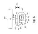
図5Hおよび図5Iに示される別の実施形態において、クランプ110は、バルーン111またはバルク材112を備える。例えば、図5Hに示される、第1の部材120の第1の外部面121は、バルーン111を備える。この実施形態において、スペーサー100の厚みは、第1の部材120の厚み105およびバルーン、バルク材または他のスペーサーデバイスの厚み103との組み合わせを含む。スペーサー100の厚みは、それぞれ、図5Hおよび5Iに示されるような第1の部材120の厚み105およびバルーン111の厚み103、または、第1の部材120の厚み105およびバルク材112厚みの103を含む。スペーサー100の厚みは寸法を測定すると、約0.007インチ〜約0.8インチの間にあり、好ましくは、0.08インチ〜0.7インチの間にあり、好ましくは約0.2インチ〜約0.6インチの間にある。 In another embodiment shown in FIGS. 5H and 5I, the
図5Hを参照して、このバルーン111は、第1の部材の外部面121上に配置され得る。同様に、図5Iに示されるように、バルク材112は、第1の部材120の外部面121上に配置され得る。1つの実施形態において、このバルーンまたはバルク材は、第1部材120の第1外部面121を完全に覆う。図5Aを再び参照して、スペーサー100が、尿道中間部のスリング手順に使用される場合、このスペーサー100は、尿道999または膀胱頚部に隣接して位置付けられる。尿道の長さは、概して3cm(約1.2インチ)までである。従って、バルーンまたはバルク材がクランプ110の第1の部材120と一緒になってスペーサー100を形成する場合、スペーサー100の長さは、それに基づいて合わせられる。図5Dを再び参照して、バルーンまたはバルク材は、第1の部材120の長さ127を約0.2インチ〜約1.2インチの間で覆うように位置付けられ、スペーサー100を形成する。1つの実施形態において、バルーン111およびバルク材112は、第1の部材120の幅125を約0.2インチ〜約0.8インチの間で覆うように位置付けられる。特定の実施形態において、バルーン111またはバルク材112は、第1の部材120の幅125を覆う。 With reference to FIG. 5H, the
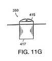
別の実施形態において、クランプ110は、圧力感受性機構すなわち圧力センサ101を備える。1つの実施形態において、図5Bにおいて図示される、クランプ110は、第1の部材120の外部面121上に圧力センサ101を備える。別の実施形態において、図5Hに示されるように、第1の部材120の第1の外部面121は、バルーン111のようなスペーサー100および圧力センサ101を備える。この圧力センサ101は、スペーサー100に適用される圧力を示す。あるいは、図5Gに示されるような、エンベロープ20上に配置されるスペーサー100は、圧力センサ101を備える。 In another embodiment, the
図5Aおよび図5Bを再び参照して、圧力センサ101は、スペーサー100によって尿道999または膀胱頚部に適用される圧力を測定するおよび/または示すために外科手順の間に使用される。このスペーサー100は、インプラント10を取り囲むエンベロープ20に隣接する(すなわち、エンベロープ20上に配置されるかまたは結合される)。スリング10を取り囲むエンベロープ20を移植する場合、尿道999または膀胱頚部とこのスリング10との間の距離を調整するために、張力が、エンベロープ20に適用される。目標圧力範囲は、インジケーターまたは圧力ゲージに設定され得る。圧力センサ101は、例えば、管の1つの端部でスペーサー100に結合され、そして管のもう一方の端部で圧力インジケーターに接続された管であり得る。適切なレベルの圧力がスペーサー100に適用される場合、圧力センサ101は、木彫とされた圧力範囲が達成されたことを示す。圧力センサ101は、種々のインジケーター手段(例えば、音、デジタル読出し、機械的インジケーター、および後押し液(fluid displacement)(すなわち、圧力計))によって、この圧力に到達したことを示し得る。圧力センサ101が、圧力範囲が満たされたことおよびエンベロープ20の配置が適切に調整されたことを示す場合、次いで、スペーサー100およびエンベロープ20は、除去され、スリング10を正しい位置に残し、そして患者の身体における解剖学的な部位にて適切な圧力のままにする。別の実施形態において、スペーサー100およびエンベロープ20が、除去された後、スペーサー100によって作り出されたギャップは、スリング10と尿道999との間に残され、そしてスリング10と尿道999との間に負荷は存在しない。スペーサー100が、エンベロープ20の周辺に固定されたクランプ110である実施形態において、患者の身体における外科的部位からエンベロープ20を除去するに先立ち、クランプ110は、エンベロープ20から放出される。 Referring again to FIGS. 5A and 5B, the
本発明に従った別の実施形態において、エンベロープ20および/またはクランプ110は薄い色がついている。1つの実施形態において、エンベロープ20の一部のみが、例えば、エンベロープ20の長手軸22の周りに薄い色がついている。エンベロープ20およびクランプ110は同じ色であってもよいし、あるいはこれらは異なる薄い色であってもよい。なお別の実施形態において、1つの様式またはデザインをエンベロープ20および/またはクランプ110に適用する。好ましい実施形態において、このエンベロープ20は薄い青色であり、この色は、患者の体内へとスリング10を移植する場合に使用される膀胱鏡(cytoscope)からの明かりの下で可視である。別の実施形態において、エンベロープ20は薄い黒色である。なお別の実施形態において、スペーサー、クランプ、薄色の領域または他の表示マークは、スリング10の配置についての可視な表示を提供する。この可視な表示を使用して、オペレーターに、スリング10の方向性について、例えば、このスリング10が表を上にしているか、表を下にしているか、または曲がっているかについて、伝え得る。1つの好ましい実施形態において、この可視な表示マークは、スリング10を囲むエンベロープ20の中央にある。引き続き図5Aについて、1つの好ましい実施形態において、クランプ110の可視の表示は尿道999と整列される。 In another embodiment according to the present invention,
なお別の実施形態において、例えば、図6に示されるように、バルーン111を備えるエンベロープは、エンベロープ20の外部表面40上に外部表面コーティング45を備える。治療薬物は、例えば外部表面コーティング45と結合されるように、結び付けられ得る。スペーサー100を有するエンベロープ20は、さらに、上記のように1つ以上の薬物および/または1つ以上のコーティングを備え得る(図1A、図1B、図2A、図2B、図3Aおよび図3B、ならびに対応する本文を参照のこと)。 In yet another embodiment, for example, as shown in FIG. 6, the envelope comprising the
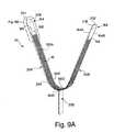
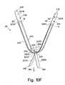
別の局面において、本発明はエンベロープに囲まれたインプラントを送達するためのシステムである。1つの実施形態において、本発明に従って、エンベロープ20は、2つ以上のスリーブ20A、スリーブ20Bを有し、これらを、第1スリーブ20Aの片方の末端が、隣接する第2スリーブ20Bの末端と重なるように配置する。これら2つのスリーブ20A、スリーブ20Bは、インプラント10を囲む。例えば、図7Aを参照すると、第1スリーブ20Aは、タブ158を備える近位末端154および遠位末端150を有する。1つの実施形態において、タブ158は第1スリーブ20Aの近位末端154を閉じる。別の実施形態において、タブ158は、患者の体内の解剖部位にてエンベロープ20を位置させるための位置決めの部材である。図7Aをなお参照すると、第1スリーブ20Aの遠位末端150は、第2スリーブ20Bの近位末端160に隣接する。第2スリーブ20Bの遠位末端164は、タブ168を備える。1つの実施形態において、タブ168は第2スリーブ20Bの遠位末端164を閉じる。別の実施形態において、このタブ168は、患者の体内の解剖部位にてエンベロープ20を位置付けるための位置決めの部材である。 In another aspect, the invention is a system for delivering an envelope surrounded by an envelope. In one embodiment, according to the present invention, the
第1スリーブ20Aの長さは、遠位末端150〜近位末端154まで測定されると、約2.0インチ〜約15.4インチの範囲であり得、好ましくは11.0インチである。第2スリーブ20Bの長さは、近位末端160〜遠位末端164まで測定されると、約2.0インチ〜約15.4インチの範囲であり得、好ましくは11.0インチである。1つの実施形態において、第1および第2のスリーブ20Aおよびスリーブ20Bは、これらの遠位末端から近位末端まで、等しい長さである。図7Bは、インプラント10、例えば中央部の尿管スリングを示し、その一部が第1スリーブ20Aの遠位末端150の中へと取り付けられ、そしてその一部が第2スリーブ20Bの近位末端160の中へと取り付けられる。スリング10の長さ(すなわち、スリング10の近位末端11から遠位末端12までの距離)は、約4.0インチ〜約24.0インチの範囲であり得るか、または約16.0インチ〜約20.0インチの間であり、好ましくは約18.0インチである。 The length of the
図7Cは、インプラント10を囲む、第1スリーブ20Aおよび第2スリーブ20Bを備えるエンベロープ20の1つの実施形態を示す。7Cに示されるように、スリーブ20Bの近位末端160をスリーブ20Aの遠位末端150の中へと挿入して、第1スリーブおよび第2スリーブ20A、20Bの重なり領域20Cを形成する。第1スリーブ20Aおよび第2スリーブ20Bの重なり領域20Cは、約0.4インチ〜約3.2インチの長さの範囲であり得、好ましくは0.8インチと1.6インチとの間である。図7Dは、第2スリーブ20Bの近位末端160が第1スリーブ20Aの遠位末端150により囲まれる位置でのエンベロープ20の領域20Cの断面の1つの実施形態を図示する。図7Cを再度参照すると、重なり領域20Cの長さ、スリング10の長さ、ならびに第1スリーブ20Aおよび第2スリーブ20Bの長さは、スリング10の近位末端11からスリーブ20Aの近位末端154まで、スリーブ20Aのセクション172を提供するように選択される。このセクションの長さは少なくとも1インチの長さである。同様に、スリング10の遠位末端12からスリーブ20Bの遠位末端164までの、スリーブ20Bのセクション174は、少なくとも1インチの長さである。これらのセクション172およびセクション174は、以下に記載のように、オベレーターによって把持されて、そしてスリング10のインプラントの位置を妨ない、患者の体からのエンベロープ20の取り外しを補助する。 FIG. 7C illustrates one embodiment of an
エンベロープ20の長手軸22は、第1側面201と第2側面202との間を測定すると、約3.6インチ〜約30.4インチの範囲であるか、または約11.8インチと約23.6インチとの間の長さであり、好ましくは19.7インチである。エンベロープ20の幅24は、エンベロープ20の上側203と底側204との間を測定すると、約0.2インチ〜約2.0インチの範囲であり得るか、または約0.5インチと約0.8インチとの間であり、好ましくは0.6インチである。 The
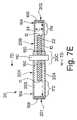
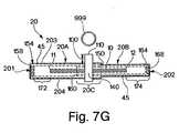
図7E、7Fおよび7Gに示される、本発明に従った別の実施形態において、クランプ110を使用して、重なり領域20C中にスリーブ20Aおよびスリーブ20Bを固定し、その結果、スリーブ20Aおよびスリーブ20Bを適所に固定して、そしてインプラント10はエンベロープ20の内部に留まる。この実施形態において、このクランプ110はエンベロープ20の重なり領域20Cの境界線の周囲に位置して、そして固定される。図7Eおよび7Fに示されるように、患者の体内の解剖部位にこのエンベロープ20を位置する手順の間に、クランプ110の第1部材120および第2部材130を近くに並べて配置して、領域20Cを固定するように、かつ第1スリーブ20Aおよび第2スリーブ20Bの解離を防ぐように、十分な圧縮力を提供する。1つの実施形態において、クランプ110または他の留め具は、スリーブ20Aおよびスリーブ20Bを解放可能に結合させて、そしてクランプ110を備えるエンベロープ20が患者の体内に位置する後、このクランプ110は留め具を外されてそして取り除かれる。次いで、スリーブ20Aおよびスリーブ20Bを取り除いて、そしてスリング10は患者の体内の解剖部位に置かれたままで残る。例えば、止血剤、針把持体、およびスプリングで負荷されたクランプのような、代替の留め具(示さない)を使用して、エンベロープのスリーブの内側に、インプラントを固定し得る。 In another embodiment according to the present invention, shown in FIGS. 7E, 7F, and 7G,
図7Fは、図7Eに図示されるエンベロープ20の側面図を示す。このエンベロープ20は、2つのスリーブ20Aおよび20B、ならびにクランプ110を備える。このクランプ110を使用して、スリーブ20Aおよび20Bを結合して、インプラント10を取り囲む。図7Fに示されるように、スリーブ20Aの遠位末端150の内部のスリーブ20Bの近位末端160は、重なり領域20Cを形成する。このクランプ110を重なり部分20Cの境界線の周りに設置する。この図では、クランプ110のヒンジ140は、エンベロープ20の側面より可視である。 FIG. 7F shows a side view of the
別の局面において、本発明は患者の体内で解剖部位にスリング10を設置するため(例えば、女性の尿失禁の処置のために、中心尿道のスリングを設置するため)の方法を含む。本発明に従った方法の1つの実施形態において、例えば、図7Eおよび図7Fに示されるように、クランプ110をスリング10の中点の周囲に置く。医者は、クランプ110を用いて、スリング10を取り囲むエンベロープの配置を指し示し得る。スリング10の取り付けの間に、このクランプ110は患者の尿道999の直下に設置される。このクランプ110はさらにスペーサー100を備え得る。例えば図5Hおよび図5Iに関して上記のように、このスペーサー100はクランプ110の第1部材120の厚さ105を備え得るか、代替的にはさらに、クランプ110上のスペーサー100の厚さは、バルーン111の厚さ103もしくは張出し器具(bulk material)112の厚さ103を含み得る。オペレーターはスペーサー100を使用してスリング10の取り付け中にスリング10の張力を調節し得る。別の実施形態において、このクランプ110はさらに、圧力センサ(例えば、図5B、5F、5Gおよび5Hに関して上記の圧力センサ101)を備え得る。この圧力センサ101はオペレーターにより使用されて、スリング10を設置すること、およびスリング10に対して正しい張力を適用することを補助する。 In another aspect, the present invention includes a method for placing a
本発明に従った方法の1つの実施形態において、オペレーターは、患者の体内の解剖部位に、図7Eおよび図7Fに示されるように、第1スリーブ20A、第2スリーブ20B、スリング10ならびにクランプ110を備えるエンベロープ20を設置する。本発明に従った1つの実施形態において、オペレーターがスリング10の位置および/または張力に納得する場合、クランプ110を切り離し、エンベロープ20から解除され、そして患者の体から取り除かれ得る。次いで、オペレーターは、スリーブ部分174および172をそれぞれ把持して引く抜くことにより、患者の体から第2スリーブ20Bおよび第1スリーブ20Aを取り除き得る。スリング10の取り付けおよび張力を維持してそしてスリング10器具が伸びるのを避けるように慎重に、クランプ110ならびにスリーブ20Aおよび20Bの除去を完了させる。従って、本発明の特定の実施形態において、第1スリーブ20Aおよび第2スリーブ20Bの取り外しは、スリング10の位置に変化を全く生じない。従って、スリング10の取り付けおよび/または張力は、オペレーターが、第1スリーブ20Aおよび第2スリーブ20Bの除去の前に、体内の解剖部位にスリング10を取りつけた場合の、スリング10の取り付けおよび張力と同様に、保持される。 In one embodiment of the method according to the present invention, an operator can place a
本発明に従ったなお別の実施形態において、図7Gに示される、第1スリーブ20A、第2スリーブ20B、スリング10およびクランプ110を備えるエンベロープ20はまた、エンベロープ20の外部表面上に配置された外部表面コーティング45を備える。スリーブ20A、スリーブ20Bおよびクランプ110を備えるエンベロープ20は、さらに、上記のような1つ以上の薬物および/または1つ以上のコーティングを備え得る(図1A、図1B、図2A、図2B、図3Aおよび図3B、ならびに対応する本文を参照のこと)。 In yet another embodiment according to the present invention, the
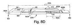
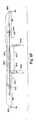
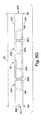
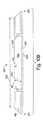
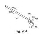
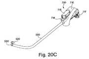
別の局面において、本発明は、エンベロープおよびインプラントの送達のためのシステムを含む。図8Aに示される1つの実施形態において、このシステムは、2つ以上のスリーブ20A、20B、および1つ以上のタブ188、タブ198、タブ208、タブ218を備えるエンベロープ20を含む。これらタブ188、タブ198、タブ208およびタブ218は、患者の体内からのエンベロープ20の取り付けおよび/または除去を容易にする。 In another aspect, the present invention includes a system for delivery of envelopes and implants. In one embodiment shown in FIG. 8A, the system includes two or
図8Aを参照すると、本発明に従った1つの実施形態において、このシステムは、第1スリーブ20A、第2スリーブ20B、タブ188、タブ198およびエンベロープヒンジ200を備えるエンベロープ20を備える。このエンベロープ20は、インプラント10を取り囲む。例えば、図8Bは、図8Aに図示されるエンベロープ20の第1スリーブ20Aを図示する。第1スリーブ20Aは、内部表面30、外部表面40、近位末端154および遠位末端150を備える。第1スリーブ20Aは、第1内腔185Aを有する。長手軸22Aに沿った近位末端154と遠位末端150との間の第1スリーブ20Aの長さは、約4.0インチと約28.0インチとの間であり、好ましくは約20.0インチである。第1スリーブ20Aの垂直軸24Aは、約0.2インチ〜約2.0インチの間に及び、好ましくは約0.4インチと約0.8インチの間であり、好ましくは0.6インチである。 Referring to FIG. 8A, in one embodiment according to the present invention, the system comprises an
図8Bをなお参照すると、本発明の1つの実施形態において、矢印172および矢印174により示される2つの角が、第1スリーブ20Aに、切り込まれる。これらの角172および角174は、図8Bに図示されるスリーブ20Aの長手軸22Aから、約20°〜約100°の範囲で切り込まれるか、または約30°〜約70°であり、好ましくは、約60°である。1つの実施形態において、この2つの角172および角174は、約0.01インチと約0.05インチとの間の距離で第1スリーブ20Aに切り込まれ、好ましくは約0.04インチである。1つの実施形態において第1スリーブ20Aに切り込まれた距離は、このスリーブ20A材料の厚さと等しい。角172および角174、ならびにそれらの配置は、以下に示されるように、例えば裂け目のための開始点を提供することにより、このスリーブ20Aをタブ188で裂くことを容易にし得る。スリーブ20Aの遠位末端150の部分は、この遠位末端150から角172まで、および遠位末端150から角174までの長手軸22Aに沿って切り取られる。一般的に、遠位末端150から各それぞれの角までの長手軸22Aに沿って切り取られる第1スリーブ20Aの量は、実質的に同じである。第1スリーブ20Aは第1内腔185Aを有して、そしてその構造は管のようであるので、第1スリーブ20Aが切り取られた後、遠位末端150部分は、図8Cおよび図8Dに図示されるような、上面部150Aおよび底面部150Bを有する。角174から上面部150Aの末端150までの第1スリーブ20Aの長手軸22Aは、約2.0インチ〜約14.0インチの間に及び得、好ましくは約10.0インチである。上面部150Aの幅は、この幅がエンベロープ20の第1スリーブ20Aの第1内腔185Aの内径と等しいか、またはそれよりも小さいような大きさである。例えば、上面部150Aの幅は、約0.1インチと約2.0インチとの間に及び得る。 Still referring to FIG. 8B, in one embodiment of the invention, the two corners indicated by
図8Cをなお参照すると、タブ188は上面部150Aの末端と繋げられ得る。このタブ188は、上面部150Aの末端150の幅を補うように成形され得る。タブ188は、例えば、上面部150Aの末端150に接着する接着剤を備え得る。別の実施形態においてタブ188は、接着剤、ステープル、加熱接着剤または当業者に公知の他の方法によって、上面部150Aと繋がれた厚紙を備え得る。タブ188が例えばTYVEK(登録商標)のような種々の医用グレードの物質を備え得、それら物質は、第1スリーブ20Aの上面部150Aと繋がれ得ることが、企図される。あるいは、上面部150Aの末端150は、タブ188に成形され得る。この実施形態において、このタブ188はスリーブ20Aまたはスリーブ20Bの材料上にエンボス加工された組織を有し得るか、またはスリーブ20Aもしくはスリーブ20Bの材料のさらなる層を末端150と繋いでタブ188を形成し得る。1つの実施形態において、このさらなる層は着色され得る。 Still referring to FIG. 8C, the
図8Dに示されるように、1つの実施形態において、タブ188と結合された上面部150Aは、第1スリーブ20Aの第1内腔185Aの中へと第1スリーブ20Aの近位末端154に向かって引き込まれる。従って、エンベロープが平坦にあり得ることを確認するために、上面部150Aの幅は、好ましくは、第1内腔185Aの内径と等しいか、またはそれよりも小さいような大きさであり、その結果、上面部150Aが第1内腔185Aの内部へと引き込まれる場合にスリーブ20Aが平らである。 As shown in FIG. 8D, in one embodiment, the
特定の実施形態において上面部150Aはスリーブ20Aの中には完全には引き込まれず、その結果、上面部150Aの重なり部位150Cは、第1スリーブ20Aの外部表面40上に残る。この重なり部位150Cは、約0.04インチ〜約1.2インチの間の範囲であり、好ましくは約0.3インチである。底面部150Bの長さは、角172および角174から、長手軸22Aに沿って、そして底面部150Bの遠位末端150へと計測すると、約2.0インチ〜約14.0インチの間に及び得、好ましくは約10.0インチである。 In certain embodiments, the
図8Eは、図8Aに示されるエンベロープ20の第2スリーブ20Bを図示する。この第2スリーブ20Bは、内部表面30、外部表面40、近位末端160および遠位末端164を有する。この第2スリーブ20Bは、第2内腔185Bを備える。長手軸22Bに沿った、近位末端160と遠位末端164との間の第2スリーブ20Bの長さは、約4.0インチと約28.0インチとの間であり、好ましくは、約20.0インチである。第2スリーブ20Bの垂直軸24Bは、約0.2インチ〜約2.0インチの間に及び、好ましくは約0.4インチと約0.8インチの間であり、好ましくは約0.6インチである。 FIG. 8E illustrates the
図8Eをなお参照すると、本発明の1つの実施形態において、矢印172および矢印174により示される2つの角、第2スリーブ20Bに、第2スリーブ20Bの長手軸22Bから、約20°〜約100°の範囲で、または約30°〜約70°であり、好ましくは、約60°で切り込まれる。1つの実施形態において、この2つの角172および角174は、約0.01インチと約0.05インチとの間の距離で第2スリーブ20Bに切り込まれ、好ましくは約0.04インチである。第2スリーブ20Bは、この近位末端160から角172まで、および近位末端160から角174までの長手軸22Bに沿って切り取られる。一般的に、近位末端160から各それぞれの角172および174までの長手軸22Bに沿って切り取られる第2スリーブ20Bの量は、実質的に同じである。第2スリーブ20Bの第2内腔185Bは、管のような構造を備える。管のような第2スリーブ20Bが切り取られた後、近位末端160は、図8Eに図示されるような、上面部160Aおよび底面部160Bを有する。角172および角174から末端部160Bまでの第2スリーブ20Bの長手軸22Bは、約2.0インチ〜約14.0インチの間に及び得、好ましくは約10.0インチである。上面部160Aの幅は、好ましくは、第2内腔185Bの内径と等しいか、またはそれよりも小さいような大きさであり、その結果、スリーブ20Bは、上面部160Aが第2内腔185Bの内部へと引き込まれる場合に水平のままである。上面部160Aの幅は、約0.1インチと約2.0インチとの間に及び得る。 Referring still to FIG. 8E, in one embodiment of the present invention, the two corners indicated by
図8Eをなお参照すると、タブ198は上面部160Aの末端と繋げられ得る。このタブ198は、上面部160Aの末端160の幅を補うように成形され得、そしてタブ198は、タブ188について上に記載したように構築され得る。タブ198と接続された上面部160Aは、第2スリーブ20Bの第2内腔185Bの中へとスリーブ20Bの遠位末端164に向かって引き込まれる。特定の実施形態において、上面部160Aは、スリーブ20Bの中には完全には引き込まれず、その結果、上面部160Aの重なり部位160Cは、第2スリーブ20Bの外部表面40上に残る。この重なり領域160Cは、約0.04インチ〜約1.2インチの間の範囲であり、好ましくは約0.3インチである。底面部160Bの長さは、角172および角174から、長手軸22Bに沿って、そして底面部160Bの近位末端160へと測定すると、約2.0インチ〜約14.0インチの間に及び得、好ましくは約10.0インチである。 Still referring to FIG. 8E, the
図8Fおよび図8Gに示されるように、第1スリーブ20Aの底面部150Bは、第1スリーブ20Aの長手軸22Aに対して約90°の角度に取り付けられる。同様に、第2スリーブ20Bの底面部160Bは、第2スリーブ20Bの長手軸22Bに対して約90°の角度に取り付けられる。これらスリーブ20Aおよびスリーブ20Bは、お互い近位に整列され、その結果、スリーブ20Aおよびスリーブ20Bそれぞれの底面部150Bおよび底面部160Bはお互いに向き合う。 As shown in FIGS. 8F and 8G, the
ここで図8Hおよび図8Iを参照すると、底面部150Bおよび底面部160Bは、お互いに接着、ステープル、熱接着剤または当業者に公知の他の方法によって繋げられる。図8Fおよび図8Gに示されるように、第1スリーブ20Aの近位末端154および第2スリーブ20Bの遠位末端164は、スリーブ20Aおよびスリーブ20Bにより形成される、エンベロープ20の反対の末端上に位置付けられる。図8Hおよび図8Iを再度参照すると、スリーブ20Aおよびスリーブ20Bの底面部150Bおよび底面部160Bは、エンベロープ20のヒンジ200を形成する。このエンベロープ20は、近位末端154および遠位末端164を有し、スリーブ20Aおよび20Bそれぞれの近位末端154および遠位末端164により形成される。図8Gを再度参照すると、エンベロープ20の長さは、近位末端154(これは第1末端201と同じである)から遠位末端164(これは第2末端202と同じである)までの長手軸22に沿って測定すると、約4.0インチから約28.0インチの間の範囲であるか、または約12.0インチと約24.0インチとの間であり、最も好ましくは20.0インチである。 Referring now to FIGS. 8H and 8I, the
図8G〜8Iを参照すると、エンベロープ20のスリーブ20Bの重なり領域160Cは、エンベロープ20のスリーブ20Aの重なり領域150Cの先端に位置し得る。第1スリーブ20Aの、残りのチューブ様の部分に隣接する重なり領域160Cの長さ(すなわち、160C’)は、約0.02インチ〜約0.06インチの間の範囲であり得、好ましくは0.04インチである。図8Aを再度参照すると、この重なり領域はエンベロープ20の内部のインプラント10を保護し、このエンベロープ20は、スリーブ20Aおよびスリーブ20Bを備える。例えば、このエンベロープ20が中央部の尿路スリングを移植するために使用される実施形態において、エンベロープ20の重なり領域150Cおよび160Cは、例えば、外科手術で使用される止血剤によって生じるスリングの伸長を防ぐ。 8G-8I, the
図8Jに図示される別の実施形態において、矢印212および矢印214によって表される角は、第1スリーブ20Aの近位末端154中に刻まれて、そしてスリーブ20Aは図示されるように実質的に削り取られて、スリーブ20Aの末端に細い部分を形成する。スリーブ20Aのチューブ様の近位末端154が削り取られる後、近位末端154は上面部154Aおよび底面部154B(示さず)を有する。上面部154Aおよび底面部154Bは、お互いに分けられている。角212から上面部154Aの近位末端154までの第1スリーブ20Aの長手軸は、約0.6インチ〜約4.0インチの間に及び得、好ましくは約1.2インチと約2.0インチとの間である。上面部154Aの垂直軸は、約0.1インチと約2.0インチとの間に及び得る。好ましい実施形態において、上面部154Aの垂直軸は、スリーブ20Aの上面部150Aの幅と等しく、このことから、上面部150Aはこのエンベロープから容易に裂けて離れ得る。図8Jおよび図8Kを参照すると、近位末端154が削り取られて近位上面部154Aおよび近位底面部154B(示さず)を形成する場合、第1スリーブ20Aの第1内腔185Aを介して近位末端154の方へタブ188と結合される上面部150Aを引き抜くことは、容易にされる。セクション154Aと154Bとの開口部は、タブ188に接近して、上面部150Aを第1スリーブ20Aを介して近位末端154の方へと引き抜くことを容易にする。いくつかの実施形態において、このタブ188は面154Aと154Bとの間で引き抜かれる。次いで、図8Jに示されるように、1つの実施形態において、タブ208を使用して、近位上面部154Aおよび近位底面部154Bを繋ぎ得る。このタブ188としては、タブ188に関して上に記載されるように、接着テープ、接着された厚紙、または他の物質を備え得る、これらは上面部および底面部の154Aおよび154Bそれぞれを一緒に繋ぎ得る。1つの実施形態において、タブ208が近位の上面部および底面部を繋ぐ後、末端154周囲において、スリーブ20Aの開口部は上面部と底面部の154Aと154Bとの間に依然として残る。このタブ188は、この開口部を介して接近され、そして引き抜かれ得るが、タブ208はスリーブ20Aの末端154に残る。 In another embodiment illustrated in FIG. 8J, the corners represented by
同様に、図8Kを参照すると、スリーブ20Bの遠位末端164は、実質的に図8Jに図示されるように、角212、角214で削り取られてエンベロープ20の各末端に狭い部位を形成する。従って、遠位の上面部164Aおよび遠位の底面部164B(示さず)が形成される。この遠位上面部164Aおよび遠位底面部164Bは分けられるので、タブ198と結合された上面部160Aを、スリーブ20Bの第2内腔を通るスリーブ20B内部表面30を介して遠位末端164の方へと引き抜くことは、容易にされる。1つの実施形態において、タブ218を使用して、遠位上面部164Aおよび遠位底面部164Bをお互いと繋ぐ。スリーブ20Aに関して上に記載されるように、このタブ218は、スリーブ20Bの末端164に取りつけられて、遠位の上面部と底面部の154Aと154Bとの間の開口部を残し得、ここで、タブ198はアクセスされ得、そして引き抜かれ得る。 Similarly, referring to FIG. 8K, the
図8Fおよび図8Gに示されるように、スリーブ20Aおよびスリーブ20Bを繋いで、エンベロープ20を形成する。第1内腔185Aおよび第2内腔185Bはエンベロープ20の単一内腔185を形成する。ここで図8Hを参照すると、スリーブ20Aおよびスリーブ20Bの繋がった底面部150Bおよび底面部160Bは、エンベロープ20のヒンジ200を形成する。種々の方法(例えば、熱接着剤、接着剤、またはステープル)を使用して、底面部150Bおよび160Bを繋ぎ得る。例えばTYVEK(登録商標)のような、これらの面を一緒に結合可能な代替の医用グレードの物質を使用し得る。ヒンジ200の長さは、約2.0インチ〜約14.0インチの長さの範囲であり得る。このヒンジ200は、より短い長さまで削り取られて、これはインプラントを移植する方法(図9B〜9Dに従って、以下に記載される)の間に、オペレーターにより把持され得る。 As shown in FIGS. 8F and 8G, the
図9Aは、エンベロープ20の内腔185中に位置するインプラント10の1つの実施形態を図示する。この実施形態において、重なり領域150Cおよび160Cは、エンベロープ20の中に囲まれたインプラント10を覆う。 FIG. 9A illustrates one embodiment of the
本発明に従った別の実施形態において、図8F、図8Gおよび図8Hを参照すると、スリーブ20Aおよび20Bがヒンジ200にて繋げられる後であるが、タブ208およびタブ218がエンベロープ20と繋げられる前に、インプラント10はエンベロープ20中に設置される。このインプラント(例えば、スリング10)は、エンベロープ20の内腔185の中へと手動で挿入され得る。別の実施形態において、このスリング10は、第1スリーブ20Aの第1内腔185A中に手動で、そして/または把持器具の補助を伴って、設置される。次いで、スリーブ20Bはヒンジ200を用いてスリーブ20Aと繋げられて、エンベロープ20を形成する。スリング10の残りの部分は、ヒンジ200の形成の前または後に、スリーブ20Bの第2内腔185B中に設置され得る。 In another embodiment according to the present invention, referring to FIGS. 8F, 8G, and 8H, the
図8Aおよび図9A〜9Dに関して、別の局面では、本発明は患者の体内に解剖部位にてインプラントを設置するための方法を含む。本発明の方法の1つの実施形態に従って、オペレーターはスリング10(例えば、図9Aに図示される)を囲むエンベロープ20を、解剖部位(例えば、尿道999または膀胱口)に設置する。図9Aおよび図9Bを参照すると、オペレーターはエンベロープ20の近位上面部154Aと結合したタブ208にアクセスする。図9Cを参照すると、近位末端154と結合されたタブ208は、オペレーターによって取り除かれ、これによって近位先端部分154Aが近位底面部154Bから切り離される。 8A and 9A-9D, in another aspect, the invention includes a method for placing an implant at a dissection site within a patient. In accordance with one embodiment of the method of the present invention, the operator places an
ここで図9Dを参照にして、操作者はヒンジ200をつかみ、そして矢印189によって示される方向にタブ188を一斉に進める。頂部部分150Aに連結したタブ188による力は、第1スリーブ20Aの頂部部分に従ってエンベロープ20を引裂く。その後、スリーブ20Aの頂部部分150Aは、単一片でエンベロープ20から引裂かれて移植スリング10を曝露する。タブ188、頂部部分150A、スリーブ20Aの頂部、および近位の頂部部分154Aは、エンベロープ20から引裂かれ、そして移植スリング10が曝露される。スリング10の曝露された部分は、尿道999に隣接している。 Referring now to FIG. 9D, the operator grabs the
なお図9Dを参照にして、タブ218に連結した遠位端164は、同様に除去され(示されていない)、そして遠位頂部部分164Aおよび遠位底部分164Bは、連結されない。操作者は、ヒンジ200をつかみ、そしてタブ198を一斉に引く。頂部部分160Aに連結したタブ198に及ぼされる力は、エンベロープ20から離れたスリーブ20Bのこれらの部分を引裂く。従って、タブ198、頂部部分160A、スリーブ20Bの頂部、および遠位の頂部部分164Aは、エンベロープ20から除去される。予め封じ込めておいたスリング10の一部は、これによって曝露される。最終的に、ヒンジ200は、エンベロープ20の残り部分にそって除去され、そしてスリング10は、解剖学的部位(スリング10が、操作者によって位置される部位、例えば、尿道999の解剖学的部位)で患者の体内に残る。 Still referring to FIG. 9D, the
図9Eに例示される他の実施形態において、図8Dおよび図8Eに沿って記載されるスリーブ20Aおよび20Bは、第1スリーブ20Aおよび第2スリーブ20Bそれぞれの垂直軸に沿って配置される、カット220Aおよびカット220Bをさらに備える。このカット220Aおよび220Bは、スリーブ20A、20Bの上面に配置され得る。このカット220Aは、タブ188の垂直軸と等しいか、またはそれよりも長いようなサイズ、および頂部部分150Aの垂直軸と等しいか、またはそれよりも長いようなサイズにされ得、タブ188および頂部部分150Aが、カット220Aを通って容易に引き抜かれるのを可能にする、頂部部分150Aに連結しているタブ188は、カット220Aを通り抜け得、その結果タブ188またはタブ188および少なくとも頂部部分150Aの少なくとも一部は、エンベロープ20の外面40に隣接する。このカット220Bは、タブ198および頂部部分160Aの垂直軸について同様のサイズにされ得る。同様に、頂部部分160Aに連結したタブ198は、カット220Bを通り抜け得、その結果、タブ198またはタブ198および頂部部分160Aの少なくとも一部は、エンベロープ20の外面40に隣接する。従って、タブ188およびタブ198は、エンベロープ20の近位端154および遠位端164から容易に接近可能なので、タブ188およびタブ198は、通り抜けて、図9Dに参照として上記されるように、エンベロープ20内に収納されたインプラント10を曝露し得る。本発明のこの実施形態において、端部154および164は、タブ188およびタブ198を引く前にエンベロープ20から除去される必要はない。 In another embodiment illustrated in FIG. 9E, the
なお別の局面において、本発明は、図10Aに例示されるエンベロープ20を提供する。このエンベロープ20は、スリーブ20C、ならびにタブ188および198を含み、これらは、エンベロープ20の外面40に隣接する。ここで図10Bを参照して、スリーブ20Cが提供され、スリーブ20Cの長手方向軸22C(第1端部201から第2端部202)は、約12.0インチ〜約84.0インチの長さ寸法であり、そして好ましくは約50.0インチの長さである。面203と面204との間の寸法のような、スリーブ20Cの幅24Cは、約0.2インチ〜約2.0インチ、好ましくは約0.5インチと約0.8インチの長さの間、そして最も好ましくは0.6インチの範囲を有し得る。スリーブ20Cは、管腔185を含む。スリーブ20Cはまた、上面234および底面236を含む。 In yet another aspect, the present invention provides an
図10Cに例示されるように、スリーブ20Cの上面234のほぼ中間点で、カット220Cが、スリーブ20Cの長手方向軸22Cにほぼ垂直に作製される。カット220Cは、第1面221Cおよび第2面222Cを有する。第1面221Cから第2面222Cまでの寸法の、カット220Cの長さは、好ましくは、スリーブ20Cの幅と等しいか、またはそれよりも短い。いくつかの実施形態において、カット220Cの範囲は、約0.2インチ〜約2.0インチの長さである。斜方向カット224は、スリーブ20Cの底面236を介して作製され得る。カット224は、上面225および底面226を有する。斜方向カット224は、カット220Cに対して約85°と約5°との間、好ましくは約45°の角度で作製される。斜方向カット224の上面225とカット220Cの第1面221Cとの間の長さは、スリーブ20Cの横幅24Cおよび対角線224の角度によって変化し、1つの実施形態において、この長さの範囲は、約0.1インチ〜約1.5インチ、そして好ましくは0.3インチである。対角線のカット224の底面226とカット220Cの第2面222Cとの間の距離は、同様に変化し、そして1つの実施形態において、この長さの範囲は、約0.1インチ〜約1.5インチであり、そして好ましくは0.3インチである。1つの実施形態において、対角線のカット224は、その長さにそって穿孔される。 As illustrated in FIG. 10C, at approximately the midpoint of the
図10Cをなお参照にして、スリーブ20Cの第1端部201は、スリーブ20Cの第1頂部201Aおよび第1底部201Bを形成するようにトリムされ、その結果、トリムされた管腔185は、2つの別々の片、201Aおよび201Bを有する。同様に、スリーブ20Cの第2端部202は、2つの別々の片(すなわち、第2頂部202Aおよび第2底部202B)を形成するようにトリムされる。第1頂部201Aは、その幅が、スリーブ20Cの内径(すなわち、管腔185)に等しいか、またはそれよりも短いようにトリムされる。同様に、第2頂部202Aは、管腔185の直径と等しいか、またはそれよりも短い幅にトリムされる。 Still referring to FIG. 10C, the
いくつかの実施形態において、第1頂部201Aの自由端は、タブ188を含む。同様に、第2頂部202Aの自由端は、タブ198を含む。第1頂部201Aおよび第2頂部202Aにそれぞれ連結しているタブ188および198は、タブ188および図8Cについての参照とともに上記されるように構築され得る。 In some embodiments, the free end of the first top 201A includes a
ここで、図10Dを参照にして、第1頂部201Aの端部に結合するタブ188は、管腔185に折り畳まれ、そして管腔185を通る。第1頂部201Aに結合されたタブ188は、カット220Cを通り抜け、その結果、タブ188および/または第1頂部201Aの一部が、スリーブ20Cの外側上面40上に曝露される。 Referring now to FIG. 10D, a
図10Dに示されるように、第2頂部202Aの端部に結合されたタブ198は、管腔185中に折り畳まれ、そして管腔185を通る。その後、第2頂部202Aに結合されたタブ198は、管腔185中に折り畳まれ、そして管腔185をとおり、最終的に、カット220Cを通り抜け、その結果、タブ198および/または第2頂部202Aの一部もまた、スリーブ20Cの外面40上に曝露される。頂部部分に隣接する2つのタブが管腔185を通り、カット220C(第1頂部201Aは第2頂部202Aに隣接し、そして両方ともカット220C内に含まれる)を通り抜ける。1つの実施形態において、図10B〜10Eに例示されるように、対角線のカット224は、スリーブ20C内に配置される。対角線のカット224は、タブ188および第1頂部201Aならびにタブ198および第2頂部202Aを、管腔185を通してカット220Cに入れるように単純化され得る。別の実施形態において、単一のカット(例えば、対角線のカット224またはカット220C)は、1つの面(すなわち、スリーブ20Cの上面234または底面236のいずれか)のみを介して配置される。本発明に従う1つの実施形態において、図10Eに示されるように、タブ208は、第1底201Bの自由端に配置され、同様に、タブ218は、第2底202Bの自由端に配置される。タブ208および218は、タブ188および図8Cに参照として上記されるような粘着タブ、接着された厚紙、または他の材料から作製され得る。タブ208および218は、患者の体内にエンベロープを配置する際に用いられ得る。 As shown in FIG. 10D, the
図10Fは、図10A〜10Eを参照として上記される、エンベロープ20の管腔185内に配置されるインプラント10の1つの実施形態を例示する。1つの実施形態において、エンベロープは、容易に引裂かれる材料を含む。このような容易に引裂かれる材料は、図1A、1B、2A、2B、3Aおよび3Bを参照として上記され、例えば、分子配向を有する材料(例えば、直線の低密度ポリエチレン)を含み得る。インプラント10は、手動またはつかみデバイスの助けでエンベロープ20の管腔185内に配置され得る。1つの実施形態において、タブ188と198の両方および/または第1頂部201Aと第2頂部202Aの両方が、スリーブ20Cのカット220Cを介して配置された後、インプラント10が、管腔185中に配置される。 FIG. 10F illustrates one embodiment of the
図10Fに例示されるように、エンベロープ20は、インプラント10(例えば、中間の尿道のスリング)を含む。別の局面において、本発明は、患者の体内の解剖学的部位にインプラントを配置するための方法を含む。1つの実施形態において(示されていない)、第1頂部201Aの長さおよび第1底部201Bの長さを整列して、エンベロープ20が平面に横たわる場合に、タブ188および208がほぼ隣接して横たわることを可能にする。エンベロープ20の第1頂部201Aおよび第1底部201Bを介して配置されるアイレットまたは穴は整列して、図23Dおよび23Fを参照として以下に記載される連結リング環355を形成し、これらは、患者の体内への移植のための送達アセンブリ650カニューレ600に付着され得る。同様に、第2頂部202Aおよび第2底部202Bを介して配置されるアイレットは整列して、患者の体内にエンベロープ20を移植するために用いられ得る連結リング環355を形成する。 As illustrated in FIG. 10F, the
本発明の方法の1つの実施形態に従って、操作者は、例えば、図10Aおよび10F(尿道999)に例示されるような解剖学的部位にスリング10を包含するエンベロープ20を配置する。1つの実施形態において、スリング10を包含するエンベロープ20が、尿道999に隣接して配置される場合、エンベロープ20の底面236は、尿道に隣接する。従って、タブ188および198ならびに関連する第1頂部201Aの一部および第2頂部202Aの一部はそれぞれ、患者の膣から見ることが可能である。1つの実施形態において、置換手順の間、操作者は、タブ208および218が患者の体の外側部分にあるようにこれらを配置する(例えば、タブ208および218は、患者の骨盤または腹膜の外側にある)。 In accordance with one embodiment of the method of the present invention, an operator places an
一旦配置されると、操作者は、患者の膣の範囲内に配置されている、第1頂部201Aに結合されたタブ188および第2頂部202Bに結合されたタブ198にアクセスする。操作者は、第1頂部201Aに連結したタブ188をつかみ、そして190の方向にタブ188を引く。第1頂部201Aに連結したタブ188による力は、エンベロープ20の頂部部位234の一部を引裂く。その後、操作者は、第2頂部202Aに連結されたタブ198をつかみ、そして190の方向にタブ198を引く。同様に、第2頂部202Aに連結しているタブ198による力は、エンベロープ20の上面234の残りの部分を引裂く。最終的に、操作者は、タブ208を引いて患者の体からエンベロープ20の底面236を除く。いくつかの実施形態において、底面236は、2つの片に引裂かれ得、従って、例えば、このような場合において、対角線のカット224の領域において、第1底部201Bに連結したタブ208および第2底部202Bに連結したタブ198の両方が、患者の体の方向から引き離される。 Once placed, the operator has access to a
別の実施形態において、インプラント10の長手方向軸は、少なくともエンベロープ20の長さに等しい。この実施形態において、インプラント10は、タブ208および218によってエンベロープ20内に維持され得、例えば、タブが粘着性である場合、インプラントは、エンベロープ20の各端部に配置されるタブ208および218によって、エンベロープ20内に維持され得る。このような実施形態において、置換手順の間、タブ208および218が患者の体の外部に出た後、操作者は、タブ208および218を開放し得、インプラント10を置く。本発明のこの方法に従って、タブ208および218は、患者の体からエンベロープ20を除去する工程の前に開放される。 In another embodiment, the longitudinal axis of the
別の局面において、本発明は、スリング10またはスリング10を包含するエンベロープ20を、送達アセンブリ650に取り付けるための付属員350に関する。図11Aに例示される本発明の1つの実施形態において、付属品350は、第1部材400(例えば、シリンダー部材400)を含む。付着片350のシリンダー部材400は、以下に記載されるように、送達アセンブリ650の拡張管部材500と係合し得る。 In another aspect, the invention relates to an
図11Aをなお参照にして、シリンダー部材400は、少なくとも1つの管腔418を有する中空であり、そして実質的に壁414によって囲まれたシリンダーである。このシリンダー部材400は、シリンダーの一端に第1部分410、そしてシリンダーの反対の端に第2部分420をさらに含む。シリンダー部材400の高さは、0.1〜1.0インチ、好ましくは0.3インチの範囲であり、そして0.1インチ〜0.6インチ、好ましくは0.19インチの範囲の外径を有する。シリンダー部材400は、例えば、ポリエチレン/エチレン酢酸ビニル(EVA)ブレンド、ポリエチレン、ナイロン、ポリプロピレン、および熱可塑性FEPのような材料から製造される。 Still referring to FIG. 11A, the
このシリンダー部材400は、シリンダーの一端にある第1部分410および第1部分410の反対の端にある第2部分420に分けられる。第1部分410の長さは、シリンダー部材400の全体の長さの20〜40%であり、そしてシリンダーの反対の端にある第2部分420の長さは、シリンダー部材400の全体の長さの60〜80%である。本発明の1つの実施形態において、図11Aに示されるように、アペンデージ430は、シリンダー部材400の第1部分410、およびシリンダー部材400の第2部分420の界面412にあるシリンダー部材400の壁414から、外側へ伸長する。 The
図11Aをなお参照にして、本発明に従う1つの実施形態において、シリンダー部材400は、第1端415から第2端417までのシリンダー部材400の縦軸に沿って約3分の1の長さでシリンダー部材400の面から伸長するアペンデージ430をさらに備える。アペンデージ430は、実質的に平らである。アペンデージ430の形状は、患者の体内を通って移動する方向に依存して、アペンデージ430が上下に曲がるのを可能にする。以下に記載されるように、シリンダー部材400が、患者の組織を通り抜ける場合、アペンデージ430は、送達アセンブリ拡張管の形状と一致する。アペンデージ430は、シリンダー部材400に成形されるか、または安定に取り付けられるように結合される。アペンデージ430は、約0.2〜1.0インチの幅、および0.5〜2.0インチの長さ、好ましくは0.6インチ〜1.0インチまでの範囲の寸法である。アペンデージ430の製造において使用される材料としては、ポリエチレン/エチレン酢酸ビニルブレンド、ポリエチレン、ナイロン、ポリプロピレン、および熱可塑性FEPが挙げられるが、これらに限定されない。このアペンデージ430は、患者の組織を引裂いたり、組織を傷つけたりせずに通り抜けるのに十分な可撓性の材料から製造される。このアペンデージ430は、接着、熱封鎖、または他の当業者に公知の手段によって、シリンダー部材400に結合される。1つの実施形態において、シリンダー部材400は、エンベロープ20材料に熱結合される。あるいは、アペンデージ430およびシリンダー部材400は、例えば、射出成形によって、単一片として製造される。 Still referring to FIG. 11A, in one embodiment according to the present invention, the
ここで、図11Bを参照にして、アペンデージ430の自由端435は、インプラント10(例えば、雌性の尿失禁の処置のために使用される移植可能なスリング10)を包含するエンベロープまたはスリーブ20の自由端436に取り付け可能である。あるいは、アペンデージ430の自由端435は、例えば、移植デバイス10の自由端434に取り付け可能である。なお別の実施形態において、本発明に従って、自由端434は、シリンダー部材400に結合されるか、または安定に取り付けられる。 Referring now to FIG. 11B, the
従って、本発明に従って、移植可能デバイス10は、シリンダー部材400に結合されるか、さもなくば安定に取り付けられる。この移植デバイス10は、クランプで締めたり、挟んだり、突き刺したりされない。従って、部材400に結合される以外の移植可能デバイス10は自由であり、患者の体内に導入される場合、複数の平面において操作される。 Thus, according to the present invention,
アペンデージ430の自由端435およびエンベロープ20の自由端436は、例えば、熱結合、縫合結合、または接着結合によって取り付けられる。エンベロープ20にアペンデージ430を結合するために熱が使用される場合、アペンデージ430およびエンベロープ20を製造するために使用される材料のガラス遷移範囲は、十分な結合を可能にする範囲と同様でなければならない。本発明の特定の実施形態において、アペンデージ430とエンベロープ20は、同じ材料から製造され、例えば、アペンデージ430およびエンベロープ20を製造するためにしようされる材料は、ポリエチレンであり得る。 The
ここで、図12Aを参照にして、拡張管500は、細長中空部材510および先端部520(例えば、円錐先端部)を備える。細長中空部材510は、4.0〜14.0インチ、好ましくは8.0インチの長さであり、そして0.2〜0.4インチ、好ましくは0.25インチの外径である。細長中空部材510の管腔510は、0.1〜0.7インチの直径であり、好ましくは0.19インチの直径であり、そして管壁516によって囲まれている。管壁516は、0.01〜0.08インチの厚さであり、好ましくは0.03インチである。中空の細長部材510は、円錐先端部520に隣接する端部560で終わる。拡張管500を製造するために使用される材料としては、ポリエチレン、ポリプロピレン、およびナイロンが挙げられるが、これらに限定されない。 Here, referring to FIG. 12A, the
図12Bを参照して、円錐先端部520は、中空であり、そして円錐型である。円錐先端部520の底514は、細長中空部材510の端部560に隣接するように構造される。1つの実施形態において、図12Aを参照にして、円錐先端部520は、アパーチャ402を備える。 Referring to FIG. 12B, the
図12Aに例示されるように、1つの実施形態において、本発明に従って、拡張管500の壁516は、伸長された中空部材510の長軸に実質的に垂直であり、そして、円錐先端部520の基部514に近いか、実質的に隣接して配置される、カット512を備える。このカット512は、細長部材510の遠位端560を形成し、そして拡張管500の壁の周囲全体近くに伸長するが、拡張管500の細長中空部材510から円錐先端部520を分離することを短期間停止する。従って、壁516のフラップ518は、円錐先端部520を細長部材510に連結し続ける。従って、フラップ518は、図13に例示されるように、ヒンジとして作用し、細長部材510の長軸に体する円錐先端部520の少なくとも90°、好ましくは180°の関節接合を可能にする。例示されている以外の壁516に円錐先端部520を取り付ける他の手段もまた、本発明によって意図されるが、例示されるものに限定されない。 As illustrated in FIG. 12A, in one embodiment, in accordance with the present invention, the
図13を参照にして、本発明の1つの実施形態において、以下により詳細に記載されるカニューレ600は、拡張管500の細長中空部材510の管腔540中に挿入される。このカニューレ600は、カニューレ600の端部602が、実質的にヒンジ518に隣接する細長中空部材510の端部で形成される開口部542から現れるまで、中空部材510の管腔540に進められる。 Referring to FIG. 13, in one embodiment of the present invention, a
ここで、図11A〜11Nを参照にして、本発明の1つの実施形態において、シリンダー部材400の頂部415は、頂部415を通ってシリンダー部材400の管腔418内に延びる1つ以上のスリット416を含む。図11Aに例示されるように、本発明の実施形態において、シリンダー部材400の頂部415を通るスリット416は、「X」の形状であり得る。スリット416の実施形態は、例示されるものに限られず、例えば、Y型、V型、O型または曲線を含み得る。1つの実施形態において、シリンダーの頂部415は、円錐の形状を有し、これは、1つ以上のスリット416によるスリットである。頂部415および/またはスリット416の形状は、シリンダー部材400を、拡張管500の管腔540中に配置する1つの方法であることを確実にする形状を有する、シリンダー部材400を提供する。部材400の配置の1つの方法を包含するさらなる手段または形状が、用いられ得る。例示される実施形態において、部材400は、拡張管500の中空部材510の管腔540と結合するような、シリンダーとして形付けられる。従って、他の適切な結合拡張管500、管腔540、およびシリンダー部材400の形状が、例えば、四角、三角、長方形または星型のように選択され得る。1つの実施形態において、スリット416は、以下に記載されるように、カニューレ600にわたりシリンダー部材400の1方向アセンブリを可能にする。 11A-11N, in one embodiment of the present invention, the top 415 of the
シリンダー部材400の第2部分420は、シリンダー形状で中空である。第2部分420の高さは、0.07〜0.7インチであり、好ましくは0.2インチ、またはシリンダー部材400の第1部分410の高さの2〜3倍である。第部分420の寸法は、以下に記載されるように、第2部分420が拡張管500の管腔540内に位置されることを可能にするように構成される。シリンダー部材400の第1部分410および第2部分420の寸法は、シリンダー部材400が1方向で拡張管500の管腔540に入ることを可能にするように構成され得、すなわち、その結果、第2部分420は、拡張管500の管腔540中に挿入される。これらの寸法は、シリンダー部材400の第1部分410を、拡張管500の管腔540中に不適切に導入することを防ぐように選択される。拡張管500の管腔540を伴うシリンダー部材400の1方向の構成は、患者の体内のインプラント10の適切な配置を保証する。本発明の1つの実施形態において、シリンダー部材400の第2部分420の自由端417は、それが、拡張管500の管腔540に容易に配置することを可能にする面取りされた縁を有する。 The
ここで、図14を参照にして、アペンデージ430によって移植デバイス(例えば、スリング10を包含するエンベロープ20)に取り付けられたシリンダー部材400は、拡張管500の細長部材510の管腔540中に導入される。シリンダー部材400は、拡張管500の細長部材510の管腔540中に置かれ、これによって、シリンダー400を拡張管500に固定する。カニューレ600は、図15に例示されるように、カニューレ600の端部602が、スリット416を介してシリンダー部材400の頂部415から現れるまで、拡張管500の管腔540から中空シリンダー部材400の管腔418中に導入される。 Referring now to FIG. 14, the
図16を参照にして、シリンダー部材400の端部415を超えて延びたカニューレ600の末端602と共に、拡張管500の円錐先端部520は、シリンダー部材400の第1部分410の頂部にわたって回転される。従って、図17に例示されるように、シリンダー部材400のアペンデージ430は、拡張管500の細長部材510の遠位端542と拡張管500の円錐先端部520の底部514との間に閉じ込められる。この位置において、円錐先端部520は、シリンダー部材400の第1部分410を包含し、これにより、アペンデージ430によって、スリング10、またはエンベロープ20およびスリング10を、送達アセンブリ650の拡張管500に連結する。 Referring to FIG. 16, with the
なお図17を参照にして、カニューレ600は、シリンダー部材400の頂部415におけるスリット416、および円錐先端部520の末端にあるアパーチャ402を介して、さらに伸長され得る。カニューレ600の末端602が、円錐先端部520の端部あるアパーチャ402を通って現れる場合、円錐先端部520は、適所に固定され、そしてほとんど動かされ得ず、これにより、スリング10を、送達アセンブリ650の拡張管500にロックする。 Still referring to FIG. 17, the
ここで、図18Aを参照にして、本発明に従う別の実施形態において、接着片350は、円錐460およびコレット580を含む。円錐460は、接着結合、熱結合、縫合または当業者に公知の任意のほかの結合によって、インプラント10またはエンベロープに20に結合される。1つの実施形態において、ここで、図1Aおよび18Aを参照にして、エンベロープ20の第1端部201の幅24は、装着部位466で円錐460の外径の部分周辺に熱結合される。1つの特定の実施形態において、エンベロープ20の第1端201の幅24は、装着部位466で円錐460の外周の約半分をカバーする。円錐460およびコレット580は、以下のような材料から製造される;ポリプロピレン、ナイロン、アクリトニトリルブタジエンスチレン(ABS)、ポリカルボネート、好ましくはポリエチレンまたはスリーブへの熱結合を可能にするポリエチレン/エチレン酢酸ビニルブレンド。円錐460およびコレット580は、射出成形によって製造され得る。 Referring now to FIG. 18A, in another embodiment according to the present invention, the
図18Aを続けて参照すると、コレット580は、ほぼ円柱形であり、管腔590を備え、そして最も幅の広い点において、約0.3インチ〜約0.9インチ、好ましくは約0.6インチの長さ、および0.1インチ〜0.7インチ、好ましくは0.3インチの直径を有する。図18Aに例示されるコレット580の第1の端部582は、中空の円柱であり、そしてこのコレット580の長さの約25〜50%を占める。図18Aに例示されるコレット580の第2の端部584は、コレット580の第1の端部582から第2の端部585に向かって先細になっている。一実施形態において、コレット580の第1の端部582は、拡張器チューブ500の細長中空部材510の管腔540に挿入され、そしてこの拡張器チューブに連結される。コレット580が拡張器チューブ500の細長中空部材510の遠位端560に連結される実施形態において、円錐部520は、拡張器チューブ500から取り外され得る。開口部592は、コレット580の端部585に位置決めされる。コレット580のテーパー付けにより、取付け部品350が円錐部460なしで適所に進められる場合の、患者の身体中の組織の容易な通過が可能となる。 With continued reference to FIG. 18A, the
さらに図18Aを参照すると、一対のカンチレバーロッキングタブ586が、コレット580のテーパー状の第2の部分584の外面上に配置される。カンチレバーロッキングタブ586は、外力が適用された場合に内側に反り、そしてこのタブ586はその元の位置に戻り、以下に記載されるように、円錐部460上の対応するロッキングレセプタクル462とのスナップ係合を提供する。 Still referring to FIG. 18A, a pair of
さらに図18Aを参照すると、安定化突出部588が、カンチレバーロッキングタブ586が円錐部460と係合する場合に、このカンチレバーロッキングタブ586を安定化するために、このカンチレバーロッキングタブ586上に設けられる。この安定化突出部588は、コレット580を円錐部460上に固定する。 Still referring to FIG. 18A, a stabilizing projection 588 is provided on the
続けて図18Aを参照すると、一実施形態において、取付け部品350の円錐部460は、この円錐部460の第1端部461付近の管腔465の側部中の壁部463中に配置される実質的に矩形のロッキングレセプタクル462を備える。コレット580中のカンチレバーロッキングタブ586は、ロッキングレセプタクル462と係合して、このコレット580をこの円錐部460に固定する。コレット580上のロッキングレセプタクル462の数は、円錐部460上に配置されるカンチレバーロッキングタブ586の数と少なくとも同じ程度多い。本発明の別の実施形態において、このロッキングレセプタクル462は、円錐部460の管腔465の側部上の壁部463を取り囲む連続レセプタクル(図示せず)である。 With continued reference to FIG. 18A, in one embodiment, the
この円錐部460は、この円錐部の第1端部460から円錐部の第2端部464に向かって先細になっている。一実施形態において、開口部470は、第2端部464に配置される。円錐部460のテーパーは、コレット580の第2部分584のテーパーと平行である。円錐部460およびコレット580の第2部分584の類似のテーパーにより、このコレット580の第2端部584は、円錐部460の管腔465内にぴったりと嵌合し得る。円錐部460は、インプラント10またはスリーブ20の取付けのための、円錐部460の外面上の表面468を備える。 The
図18Bを参照すると、インプラントが表面468で取り付けられた円錐部460をコレット580に固定するために、コレット580の第2端部584が、円錐部460の管腔465に導入される。カンチレバーロッキングタブ586および安定化突出部588は、円錐部460の対応するロッキングレセプタクル462中に嵌合して、コレット580を円錐部460に固定する。円錐部460とコレット580との間の界面は、約0.5ポンド〜約10ポンドの間、好ましくは4ポンドの分離力に十分確実に耐えなければならない。カニューレ600は、コレット580の管腔590、円錐部460の管腔465、コレット580の開口部592、および円錐部460の開口部470を通して導入され得る。一実施形態において、カニューレ600は、コレット580の管腔590の内側にぴったりと嵌合するように、サイズ決めされる。コレット580の管腔590中にカニューレ600が存在することにより、ロッキングタブ586の内向きの反りが防がれ得る。このカニューレ600、および円錐部460とコレット580とを備える取付け部品350は、患者の身体中に、円錐部460に連結されたインプラント10またはエンベロープ20を導入するために使用され得る。コレット580は円錐部460に固定されており、このコレット580は、ロッキングタブ586を反らさずに円錐部460から取り外され得ない。円錐部640は、リーディングカニューレ600からコレットの拡張形状までの滑らかな移行を提供する。カニューレ600が取付け部品350に挿入されると、カンチレバータブ586は、円錐部460のレセプタクル462と完全に係合し、取付け部品350の円錐部およびコレットを一緒に固定して、取付け部品350がカニューレ600から取り外されるまで、カンチレバータブ586が反るのを防ぐ。 Referring to FIG. 18B, the
本発明の別の実施形態において、円錐部460は、取付け部品350の組み立ての間に、コレット580上の所定の方向への円錐部460の組立を可能にする方向付けキーを備える。 In another embodiment of the present invention, the
別の局面において、図11Aを再び参照すると、本発明は、女性の切迫尿失禁の処置のための医療用デバイス10(例えば、スリングインプラント10)を送達アセンブリ650に取り付けるための方法である。本発明の方法の一実施形態によると、シリンダー部材400は、付属部430を介して、インプラント10またはこのインプラント10を取り囲むエンベロープ20に予め取り付けられる。操作者(例えば、医師)は、このシリンダー部材400の第2部分420を、拡張器チューブ500の細長中空部材510の管腔540内に配置し、このシリンダー部材400を拡張器チューブ500に係留する。円錐形先端部520は、この円錐形先端部520がシリンダー部材400の第1部分410上に配置されるまで、ヒンジ518の周りで回転される。カニューレ600は、カニューレ600の端部602がシリンダー部材400の上部415中のスリット416を通って出てくるまで、シリンダー部材400の上部415に向かって進められる。このカニューレは、カニューレ600の端部602が円錐形先端部520中の開口部402を通って出てくるまで、さらに進められる。 In another aspect, referring again to FIG. 11A, the present invention is a method for attaching a medical device 10 (eg, a sling implant 10) to a
本発明の別の実施形態において、本発明の送達システム2は、送達アセンブリ650を備える。ここで図19Aを参照すると、一実施形態において、送達アセンブリ650は、拡張器チューブ500、カニューレ600、収縮可能点740および送達ハンドル700を備える。この収縮可能点740は、ハンドル700の遠位端714を介して、ハンドル700上のボタン713およびボタン715(以下に記載される)に操作可能に連結される。拡張器チューブ500は、ハンドル700の細長部材710上に配置される拡張ボタン717に操作可能に連結される。 In another embodiment of the present invention, the
ここで図19A〜19Hを参照すると、本発明に従う一実施形態において、ハンドル700は、細長部材710を備え、この細長部材710は、拡張器チューブ500の円錐形先端部520から最も離れている近位端712、および拡張器チューブ500の円錐形先端部520に最も近い遠位端714を有する。ハンドル700の細長部材710は、図20Dに例示される、少なくとも1つの管腔709を有し、これは、ハンドル700の長軸に平行である。細長部材710は、約4.0インチ〜14.0インチ、好ましくは8.0インチの長さであり、そして約0.5インチ〜5.0インチ、好ましくは1.5インチの直径である。ハンドル700は、近位ボタン713、遠位ボタン715および拡張ボタン717を有する。 Referring now to FIGS. 19A-19H, in one embodiment in accordance with the present invention, the
本発明の一実施形態において、近位ボタン713は、ハンドル700の一方の側部上の近位端712において、細長部材710の表面上に配置される。本発明に従う特定の実施形態において、この遠位ボタン715は、近位ボタン713と同じハンドル700の側部上の細長部材710の遠位端714において、細長部材710上に配置される。本発明に従う一実施形態において、拡張ボタン717は、近位ボタン713および遠位ボタン715が配置されるハンドル700の側部以外の側部上に配置される。例えば、図19Aを参照すると、拡張ボタン717は、近位ボタン713および遠位ボタン715が配置される細長部材710の側部の反対側の、ハンドル700の細長部材710の側部上に配置される。別の実施形態において、拡張ボタン717、近位ボタン713および遠位ボタン715は、ハンドル700の同じ側部上に配置される。 In one embodiment of the present invention, the
図19Aを再び参照すると、上記の拡張器チューブ500は、前後にスライドして、ハンドル700の細長部材710の遠位端714から外向きに延びる。拡張器チューブ500の円錐形先端部520は、拡張器チューブ500の遠位端に配置される。ここで図20Aおよび20Bを参照すると、ブッシング724が、拡張器チューブ500の近位端726中に挿入される。カフ718は、拡張ボタン717に取り付けられ、そして拡張器チューブ500の近位端726の外側を取り囲む。一実施形態において、拡張ボタン717およびカフ718は、例えば、射出成形によって単一のユニットとして製造される。一実施形態において、このブッシング724は、拡張器チューブ500がカフ718の内側にぴったりと嵌合するようなサイズにされる。このブッシング724は、拡張器チューブ500をカフ718の内側に維持し、そして拡張器チューブ500をハンドル700の内側に保持する。 Referring back to FIG. 19A, the
ここで図20Cおよび20Dを参照すると、拡張器チューブ500は、第1の位置(図20Cに例示され、ここで、拡張器チューブ500は、ハンドル700の細長部材710の遠位端714から第1の位置(または延びた位置)にある)から、第2の位置または収縮位置(図20Dに例示され、ここで、拡張器チューブ500の近位端726は、ハンドル700の細長部材710の近位端712に実質的に隣接した位置まで、ハンドル700の細長部材710の管腔709中に引っ込められる)まで、拡張ボタン717により手動でスライド式に移動可能である。 Referring now to FIGS. 20C and 20D, the
図20Eに例示される拡張器チューブの別の実施形態において、剛性リング523が、拡張器チューブ500の管腔540中の内壁に、細長中空部材510の端部542から約0.5インチ〜3.0インチ、好ましくは1.3インチのところに取り付けられる。剛性リング523は、拡張器チューブ500の管腔540中のカニューレ600の通過のためのガイドとして役立つ。別の実施形態において、1つより多い剛性リング523が、拡張器チューブ500の細長部材510中および/または拡張器チューブ500の円錐形先端部520内に存在する。この剛性リング523は、カニューレ600を誘導し、そして拡張器チューブ500の管腔内のカニューレ600の配置を安定化し、そしてこの剛性リング523は、拡張器チューブ500の中心部へカニューレ600を方向付けるように配置され得る。一実施形態において、剛性リング523は、ある角度まで先細になっており、そして拡張器チューブ500の管腔の内径と次第に接触(flush)して、拡張器チューブ500内のカニューレ600の配置を補助する。さらに別の実施形態において、この剛性リング523は、例えば、拡張器チューブ500の細長部材510および/または円錐形先端部520中に挿入され得る挿入物(例えば、管状挿入物)である。このような挿入物の外径は、細長部材510の内径と密接に対応し得、一実施形態において、この挿入物の外径は、約0.2インチであり、そして内径は、約0.14インチである。一実施形態において、この挿入物は、例えば、熱接合によって、細長部材510に連結される。ここで図21A、21Bおよび21Cを参照すると、カニューレ600は、第2の細長中空チューブ604である。このカニューレ600は、図21Bに例示されるように、拡張器チューブ500の管腔540内に挿入される。本発明に従う特定の実施形態において、カニューレ600のチューブ604は、カニューレ600の遠位端におけるカニューレ先端部602から、チューブ604の長さの約10〜75%までの弧を形成する。例えば、図19Aを参照すると、カニューレ600は、弧の凹面がハンドル700のボタン713およびボタン715と同じカニューレ600の側部上にある弧を形成する。このカニューレ600の弧は、患者の組織を通る送達システムの挿入の容易さを最適化して、このインプラント10を適切な解剖学的部位に配置するように選択される。カニューレ600は、約4.0インチ〜約14.0インチ、好ましくは8.0インチの長さであり、そして約0.05インチ〜約0.3インチ、好ましくは0.13インチの直径である。カニューレ600は、拡張器チューブ500とほぼ同じ長さである。拡張器チューブ500の最も伸長した第1の位置において、図20Cに例示されるように、カニューレ600の長さの実質的に全てが、拡張器チューブ500によって取り囲まれる。この拡張器チューブ500が、最も収縮した第2の位置にある場合、図21Cに例示されるように、このカニューレ600の約20〜50%が、拡張器チューブ500により取り囲まれる。カニューレ600は、剛性であり、そしてステンレス鋼、メッキ炭素鋼または被覆炭素鋼のような材料から製造される。 In another embodiment of the dilator tube illustrated in FIG. 20E, a
ここで図22A、22Bおよび22Cを参照すると、本発明に従う収縮可能点740は、細長部材742を備え、この細長部材742は、この細長部材742の遠位端741にテーパー状端部744を有する。収縮可能点740の細長部材742は、約4.0インチ〜約14.0インチ、好ましくは8.0インチの長さであり、そして約0.03インチ〜約0.1インチ、好ましくは0.06インチの直径である。この収縮可能点740の細長部材742は、カニューレ600の弧に対応する弧を描く。この収縮可能点740は、図22Bに例示されるように、カニューレ600の管腔610中に配置される。この収縮可能点740は、図22Cに例示される伸長した第1の位置から図20Cに例示される収縮した第2の位置まで移動可能である。 Referring now to FIGS. 22A, 22B and 22C, a
ここで図23Aを参照すると、ハンドル700上の近位ボタン713および遠位ボタン715の各々が、収縮可能点740に操作可能に連結され、そして2つの位置(第1の位置Aおよび第2の位置B)を通って移動可能である。ここで図22Aおよび22Cを参照すると、第1の位置Aにおいて、収縮可能点740のテーパー状端部744は、カニューレ600中に収縮される。第2の位置Bにおいて、収縮可能点740のテーパー状端部744は、例えば、図22Cに例示されるように、カニューレ600の遠位端602から延びる。ボタン713および715は、第2の位置から第1の位置までバネ付勢され、これは、操作者がボタン713または715を手動で保持して、このボタンを第2の位置に維持し、テーパー状端部744をカニューレ600の遠位端602から延ばすことを必要とする。図20D、22Aおよび22Cを再び参照すると、近位ボタン713が押し下げられる場合、ボタン713の下にある突出部707は、送達ハンドル700の遠位端714に向かって押され、これにより、バー705が遠位端714に向かって前方向に動く。収縮可能点740は、バー705の内側に収容され、そしてボルト743によってバー705の内側に固定される。近位ボタン713が押し下げられて、突出部707をハンドル700の遠位端714に向かって押す場合、このバーは、ハンドル700の遠位端714に向かって動く。従って、点744は、遠位方向にかつカニューレ600の外側に延びる。同様に、遠位ボタン715の下に位置する突出部708は、突出部707と同じ方向に傾けられるので、ボタン715が押し下げられる場合、点744は、遠位方向にかつカニューレ600の外側に延びる。 Referring now to FIG. 23A, each of the
送達アセンブリ650の別の実施形態において、図23Bに例示されるカニューレ600、カニューレ600の遠位端602付近のカニューレ600の部分は、カニューレ600への連結リング355の取付けを可能にするロッキングノッチ615を備える。図23Dおよび23Fに例示される連結リングは、インプラントの端部に取り付けられたループであるか、またはカニューレのノッチ615に連結するために、インプラント10の端部に配置される穴もしくはアイレットである。このループは、例えば、縫合糸またはワイヤにより形成され得、そしてループは、例えば、接着剤、熱融着、インプラント10の端部へのボルト留め、インプラント10を通して糸でつなぐこと、または他の利用可能な取付け手段によって、インプラント10の端部に係留され得る。別の実施形態(図示せず)において、連結リング355は、エンベロープ20の1以上の端部を通して配置され、カニューレ600のロッキングノッチ615へのエンベロープ20の連結が可能となる。 In another embodiment of the
図23Bに例示されるように、本発明のこの実施形態において、ボタン713およびボタン715は、3つのボタン位置(位置A、位置Bおよび位置C)を有する。ボタン713およびボタン715の位置Aにおいて、ノッチ615は、連結リング355を収容する準備のできた開口した固定されていない位置にある。ボタン713およびボタン715の位置Bにおいて、ノッチ615は、図23Cに例示されるように、閉じて固定された位置にある。位置Bにおいて、連結リング355は、ノッチ中に固定される。ボタン713およびボタン715の位置Cにおいて、収縮可能点740は、カニューレ600の遠位端602から延ばされる。ボタン713およびボタン715の位置Cは、位置Bまでバネ付勢され、その結果、操作者は、ボタンを位置Cに保持して、収縮可能点740を延ばさなければならない。 As illustrated in FIG. 23B, in this embodiment of the invention,
別の実施形態において、カニューレ600またはカニューレ600の遠位端部は、送達アセンブリ650から取り外し可能である。 In another embodiment,
本発明の別の局面は、本発明に従う送達アセンブリ650を使用して、身体中の解剖学的部位に移植可能デバイス10を送達するための方法を包含する。解剖学的部位としては、例えば、尿道中間部、前立腺、または膀胱頸部が挙げられる。この方法の一実施形態によると、経膣アプローチが、インプラント10のエンベロープ20(例えば、Boston Scientific Corporation(Natick,MA)により製造されるPINNACLE Sling)と共に使用される。スリング10は、初めに、このスリング10をシリンダー部材400に、熱接合、接着剤、または当業者に公知の他の方法によって連結することによって、送達アセンブリ650に固定される。拡張器チューブ500は、送達ハンドル700上の拡張ボタン717を、図23Aに例示される位置Eから位置Dまで動かすことによって、図20Cに例示される伸長位置に配置される。拡張器チューブ500の円錐形先端部520は、図20Cに例示される位置まで手動で開けられる(図11Aもまた参照のこと)。シリンダー部材400の第2の位置420は、図14および15に例示されるように、拡張器チューブ500の細長中空部材510の管腔540中に配置される。円錐形先端部520は、図16に示されるように、シリンダー部材400の第1の位置410の上を手動で回転される。従って、スリング10は、図17に示されるように、取付け部品350によって、送達アセンブリ650に取り付けられる。スリング10が拡張器チューブ500に固定された後、拡張器チューブ500は、ボタン717を、図23Aに例示される位置Dから位置Eまで動かすことによって、図20Cに例示される伸長位置から図21Cに例示される収縮位置まで移動される。操作者は、経膣アプローチにおいて、ハンドル700を把持し、そしてカニューレ600の遠位端602を経膣的に進めて、患者の恥骨結節の領域中の直筋膜、腹筋膜および腹腔壁を通って出す。尿道中間部の領域中のスリング10の配置について正確な位置を確認した後、拡張器チューブ500を、拡張ボタン717を第1の位置Eから第2の位置Dまで動かし、それにより拡張器チューブ500をカニューレ600の上で遠位に進めることにより、カニューレ600上を進める。カニューレ600および拡張器チューブ500は、スリング10が直筋膜を通って延びるまで、患者の組織中をさらに進められる。このスリング10は、例えば、切断によって、取付け部品350から取り外され、そしてカニューレ600および拡張器チューブ500は、患者から引き出される。この手順は、患者の反対側で繰り返される。 Another aspect of the present invention includes a method for delivering an
別の実施形態において、送達ハンドル700の管腔709は、1つ以上のロッキング領域を有し、この領域において、操作者が拡張器チューブ500を第1の位置Eから第2の位置Dまで動かす場合、この拡張器チューブ500が適所に固定され得る。この実施形態によると、操作者は、カニューレ600および拡張器チューブ500の両方を使用して、直筋膜、腹腔筋膜および腹腔壁に押し通し得、この場合この手順の間に患者の膣から恥骨結節の領域までを横切る。この実施形態によると、スリング10は、拡張器チューブ500およびカニューレ600を患者の組織を通して動かす前に、送達アセンブリ650に取り付けられ得る。あるいは、スリング10は、組織が最初に貫通された後にのみ、送達アセンブリ650に取り付けられ得る。 In another embodiment,
この方法の代替のアプローチにおいて、尿道中間部は、上記のように経膣的ではなく、腹腔壁、腹腔筋膜、および直筋膜を通して経皮的にアプローチされる。本発明に従うこの方法において、拡張器チューブ500は、ハンドル700上の拡張ボタン717を第1の位置Eから第2の位置Dまで動かすことによって、カニューレ600の上を進められる。一実施形態において、拡張ボタン717は、第1の位置Eから第2の位置Dまで、複数の位置を通って可逆的に移動可能である。図23Aに示されるように、近位ボタン713は、位置Aから位置Bまで移動して、収縮可能点740のテーパー状端部744を、カニューレ600の遠位端602を越えて延ばす。ハンドル700を堅く把持することによって、伸長した収縮可能点740および伸長した拡張器チューブ500を有するカニューレ600は、恥骨結節の領域中の直筋膜を通して進められる。カニューレ600および拡張器チューブ500は、これらが膣壁中の切開部から出てくるまで、進められる。取付け部品350に取り付けられるスリング10は、上記のように、送達アセンブリ650に固定される。カニューレ600およびスリング10が取り付けられた拡張器チューブ500は、スリング10が尿道中間部の領域中の正しい位置に配置されるまで、この切開部中に押し戻される。一旦、スリング10の配置が確認されると、このスリング10は、取付け部品350から取り外され、そして鉗子を用いて安定化される。カニューレ600および拡張器チューブ500は、身体から引き出される。同じ工程が、膣の反対側で繰り返される。 In an alternative approach of this method, the middle urethra is approached percutaneously through the abdominal wall, peritoneal fascia, and rectus fascia rather than transvaginally as described above. In this method according to the present invention, the
患者の身体中の解剖学的部位にインプラント10を移植するための方法の別の実施形態は、エンベロープ20に封入されたインプラント10を提供する工程をさらに包含し得る。この方法は、このエンベロープ20の内面、外面または内面と外面との両方を、を少なくとも1つの薬物(例えば、抗生物質)でコーティングする工程を包含する。本発明に従う方法は、エンベロープ上に分散された治療薬を、患者組織に提供する工程をさらに包含し得る。 Another embodiment of a method for implanting an
別の実施形態において、本発明の方法は、身体の解剖学的部位に、エンベロープ20内に封入されたインプラント10を配置する工程、およびこのインプラント10をこの患者の身体中の解剖学的部位に配置したまま、エンベロープ20を取り外す工程、をさらに包含し得る。さらに別の実施形態において、本発明の方法は、エンベロープ20の引き裂き可能領域50で、エンベロープ20を引き裂く工程、およびこのエンベロープ20を身体から取り出す工程、をさらに包含し得る。 In another embodiment, the method of the present invention includes placing an
別の実施形態において、本発明の方法は、インプラント10を患者の身体中の標的解剖学的部位に配置するための、スペーサー100を提供する工程を包含する。この方法は、圧力センサ101によってスリング10に付与された張力を測定する工程をさらに包含し得る。 In another embodiment, the method of the present invention includes providing a
本明細書中に記載されるものの改変、変更および他の実施は、主張されるように本発明の精神および範囲から逸脱することなく、当業者により行われる。従って、本発明は、上記の例示的な説明により規定されず、そのかわり上記の特許請求の範囲の精神および範囲により規定されるべきである。 Modifications, changes and other implementations of what is described herein will be made by those skilled in the art without departing from the spirit and scope of the invention as claimed. Accordingly, the invention is not to be defined by the foregoing illustrative description, but instead should be defined by the spirit and scope of the following claims.
(図面の簡単な説明)
図面において、同様の参照文字は、一般に、異なる図面を通じて同じ部分に言及する。また、図面は必ずしもスケール通りではなく、代わりに、本発明の原理を例示するに際し一般に配置されていることを強調する。(Brief description of the drawings)
In the drawings, like reference characters generally refer to the same parts throughout the different views. It is also emphasized that the drawings are not necessarily to scale, but instead are generally arranged to illustrate the principles of the invention.
Claims (36)
Translated fromJapanese解剖部位を支持するような形態の、支持スリング;
内面および外面を備えるエンベロープであって、該支持スリングを少なくとも部分的に囲む、エンベロープ;および
該エンベロープの該内面または外面の少なくとも1方上に配置される、薬物、を備える、システム。A system for implanting asupport sling anatomical site in the body of a patient, said system comprising:
A support sling configured to support the anatomical site;
A envelope comprising an inner surface and an outersurface,at least partially surroundingthe support sling, the envelope;and
A drug disposed on at least one of the inner or outer surface of the envelope.
Applications Claiming Priority (3)
| Application Number | Priority Date | Filing Date | Title |
|---|---|---|---|
| US27484301P | 2001-03-09 | 2001-03-09 | |
| US28686301P | 2001-04-26 | 2001-04-26 | |
| PCT/US2002/007076WO2002071953A2 (en) | 2001-03-09 | 2002-03-07 | System for implanting an implant and method thereof |
Related Child Applications (1)
| Application Number | Title | Priority Date | Filing Date |
|---|---|---|---|
| JP2008110528ADivisionJP2008212703A (en) | 2001-03-09 | 2008-04-21 | System and method for implanting an implant |
Publications (3)
| Publication Number | Publication Date |
|---|---|
| JP2005505313A JP2005505313A (en) | 2005-02-24 |
| JP2005505313A5 JP2005505313A5 (en) | 2005-06-09 |
| JP4181410B2true JP4181410B2 (en) | 2008-11-12 |
Family
ID=38779879
Family Applications (1)
| Application Number | Title | Priority Date | Filing Date |
|---|---|---|---|
| JP2002570915AExpired - Fee RelatedJP4181410B2 (en) | 2001-03-09 | 2002-03-07 | System and method for implanting an implant |
Country Status (7)
| Country | Link |
|---|---|
| US (1) | US7025772B2 (en) |
| EP (1) | EP1365688B1 (en) |
| JP (1) | JP4181410B2 (en) |
| AU (2) | AU2006222727B9 (en) |
| CA (1) | CA2440153C (en) |
| DE (1) | DE60239188D1 (en) |
| WO (1) | WO2002071953A2 (en) |
Families Citing this family (265)
| Publication number | Priority date | Publication date | Assignee | Title |
|---|---|---|---|---|
| US6599235B2 (en) | 1997-03-18 | 2003-07-29 | American Medical Systems Inc. | Transvaginal bone anchor implantation device |
| US6039686A (en) | 1997-03-18 | 2000-03-21 | Kovac; S. Robert | System and a method for the long term cure of recurrent urinary female incontinence |
| US6382214B1 (en) | 1998-04-24 | 2002-05-07 | American Medical Systems, Inc. | Methods and apparatus for correction of urinary and gynecological pathologies including treatment of male incontinence and female cystocele |
| WO2001037728A1 (en) | 1999-11-24 | 2001-05-31 | Nuvasive, Inc. | Electromyography system |
| EP1665991B1 (en) | 2000-06-05 | 2017-12-13 | Boston Scientific Limited | Devices for the treatment of urinary continence |
| US6638211B2 (en) | 2000-07-05 | 2003-10-28 | Mentor Corporation | Method for treating urinary incontinence in women and implantable device intended to correct urinary incontinence |
| FR2811218B1 (en) | 2000-07-05 | 2003-02-28 | Patrice Suslian | IMPLANTABLE DEVICE FOR CORRECTING URINARY INCONTINENCE |
| US6702827B1 (en) | 2000-10-06 | 2004-03-09 | American Medical Systems | Sling adjustment and tensioning accessory |
| US20060205995A1 (en) | 2000-10-12 | 2006-09-14 | Gyne Ideas Limited | Apparatus and method for treating female urinary incontinence |
| GB0025068D0 (en) | 2000-10-12 | 2000-11-29 | Browning Healthcare Ltd | Apparatus and method for treating female urinary incontinence |
| US8167785B2 (en) | 2000-10-12 | 2012-05-01 | Coloplast A/S | Urethral support system |
| US6582443B2 (en) | 2000-12-27 | 2003-06-24 | Ams Research Corporation | Apparatus and methods for enhancing the functional longevity and for facilitating the implantation of medical devices |
| US6652450B2 (en) | 2001-01-23 | 2003-11-25 | American Medical Systems, Inc. | Implantable article and method for treating urinary incontinence using means for repositioning the implantable article |
| US6641525B2 (en) | 2001-01-23 | 2003-11-04 | Ams Research Corporation | Sling assembly with secure and convenient attachment |
| US7229453B2 (en) | 2001-01-23 | 2007-06-12 | Ams Research Corporation | Pelvic floor implant system and method of assembly |
| US20020161382A1 (en)* | 2001-03-29 | 2002-10-31 | Neisz Johann J. | Implant inserted without bone anchors |
| US6612977B2 (en) | 2001-01-23 | 2003-09-02 | American Medical Systems Inc. | Sling delivery system and method of use |
| US20020147382A1 (en) | 2001-01-23 | 2002-10-10 | Neisz Johann J. | Surgical articles and methods |
| US7070556B2 (en) | 2002-03-07 | 2006-07-04 | Ams Research Corporation | Transobturator surgical articles and methods |
| US9149261B2 (en) | 2001-03-09 | 2015-10-06 | Boston Scientific Scimed, Inc. | Systems, methods and devices relating to delivery of medical implants |
| US7364541B2 (en) | 2001-03-09 | 2008-04-29 | Boston Scientific Scimed, Inc. | Systems, methods and devices relating to delivery of medical implants |
| DE60223502T2 (en) | 2001-03-09 | 2008-11-13 | Boston Scientific Ltd., St. Michael | MEDICAL SLING |
| US8033983B2 (en)* | 2001-03-09 | 2011-10-11 | Boston Scientific Scimed, Inc. | Medical implant |
| US8915927B2 (en) | 2001-03-09 | 2014-12-23 | Boston Scientific Scimed, Inc. | Systems, methods and devices relating to delivery of medical implants |
| GB0108088D0 (en) | 2001-03-30 | 2001-05-23 | Browning Healthcare Ltd | Surgical implant |
| EP1417000B1 (en) | 2001-07-11 | 2018-07-11 | Nuvasive, Inc. | System for determining nerve proximity during surgery |
| US7037255B2 (en) | 2001-07-27 | 2006-05-02 | Ams Research Corporation | Surgical instruments for addressing pelvic disorders |
| US7407480B2 (en) | 2001-07-27 | 2008-08-05 | Ams Research Corporation | Method and apparatus for correction of urinary and gynecological pathologies, including treatment of incontinence cystocele |
| JP2005503857A (en) | 2001-09-25 | 2005-02-10 | ヌバシブ, インコーポレイテッド | Systems and methods for performing surgical procedures and surgical diagnosis |
| US20040073235A1 (en)* | 2001-10-01 | 2004-04-15 | Lund Robert E. | Surgical article |
| US6648921B2 (en) | 2001-10-03 | 2003-11-18 | Ams Research Corporation | Implantable article |
| US6911003B2 (en) | 2002-03-07 | 2005-06-28 | Ams Research Corporation | Transobturator surgical articles and methods |
| AU2003213688B2 (en)* | 2002-03-07 | 2008-10-02 | Ams Research Corporation | Transobturator surgical articles and methods |
| US7357773B2 (en) | 2002-03-07 | 2008-04-15 | Ams Research Corporation | Handle and surgical article |
| USD534650S1 (en) | 2002-05-16 | 2007-01-02 | Ams Research Corporation | Handle for a surgical instrument |
| US7582058B1 (en) | 2002-06-26 | 2009-09-01 | Nuvasive, Inc. | Surgical access system and related methods |
| CN101919722A (en)* | 2002-07-31 | 2010-12-22 | 微温森公司 | The vascular occluding device of three-part coaxial |
| CA2492630C (en) | 2002-08-02 | 2009-01-13 | C.R. Bard, Inc. | Self anchoring sling and introducer system |
| EP1803415B1 (en) | 2002-08-14 | 2016-06-01 | Boston Scientific Limited | Medical implant |
| CA2705609C (en) | 2002-08-14 | 2016-10-25 | Boston Scientific Limited | Systems, methods and devices relating to delivery of medical implants |
| US8137284B2 (en) | 2002-10-08 | 2012-03-20 | Nuvasive, Inc. | Surgical access system and related methods |
| USD543626S1 (en) | 2002-11-27 | 2007-05-29 | Ams Research Corporation | Handle for a surgical instrument |
| AU2003259834A1 (en) | 2002-12-17 | 2004-07-29 | Boston Scientific Limited | Spacer for sling delivery system |
| US7691057B2 (en) | 2003-01-16 | 2010-04-06 | Nuvasive, Inc. | Surgical access system and related methods |
| US7819801B2 (en) | 2003-02-27 | 2010-10-26 | Nuvasive, Inc. | Surgical access system and related methods |
| GB0307082D0 (en) | 2003-03-27 | 2003-04-30 | Gyne Ideas Ltd | Drug delivery device and method |
| EP1610714A2 (en) | 2003-03-28 | 2006-01-04 | Analytic Biosurgical Solutions - ABISS | Implant for treatment of a rectocele and device for placement of said implant |
| US7494495B2 (en) | 2003-03-28 | 2009-02-24 | Coloplast A/S | Method and implant for curing cystocele |
| FR2852813B1 (en)* | 2003-03-28 | 2005-06-24 | Analytic Biosurgical Solutions | INTRODUCER AND PERFORATOR GUIDE FOR THE IMPLEMENTATION OF A BANDLET IN THE HUMAN BODY |
| KR101146946B1 (en) | 2003-04-09 | 2012-05-22 | 잇판자이단호진 가가쿠오요비겟세이료호겐쿠쇼 | Process for preparing albumin preparations |
| US7361138B2 (en) | 2003-07-31 | 2008-04-22 | Scimed Life Systems, Inc. | Bioabsorbable casing for surgical sling assembly |
| US8545386B2 (en) | 2003-08-14 | 2013-10-01 | Boston Scientific Scimed, Inc. | Surgical slings |
| DE602004023314D1 (en) | 2003-08-14 | 2009-11-05 | Boston Scient Ltd | SURGICAL SLINGS |
| US7811303B2 (en)* | 2003-08-26 | 2010-10-12 | Medicine Lodge Inc | Bodily tissue dilation systems and methods |
| US7485099B2 (en)* | 2003-09-18 | 2009-02-03 | Theodore Benderev | Systems and methods for determining pressure and spacing relating to anatomical structures |
| US7347812B2 (en) | 2003-09-22 | 2008-03-25 | Ams Research Corporation | Prolapse repair |
| JP4463819B2 (en) | 2003-09-25 | 2010-05-19 | ヌヴァシヴ インコーポレイテッド | Surgical access system |
| US7905840B2 (en) | 2003-10-17 | 2011-03-15 | Nuvasive, Inc. | Surgical access system and related methods |
| EP1696803B1 (en)* | 2003-11-17 | 2016-09-28 | Boston Scientific Limited | Systems relating to associating a medical implant with a delivery device |
| US7351197B2 (en) | 2004-05-07 | 2008-04-01 | Ams Research Corporation | Method and apparatus for cystocele repair |
| US7811222B2 (en) | 2004-04-30 | 2010-10-12 | Ams Research Corporation | Method and apparatus for treating pelvic organ prolapse |
| US7500945B2 (en) | 2004-04-30 | 2009-03-10 | Ams Research Corporation | Method and apparatus for treating pelvic organ prolapse |
| AU2005240170B2 (en) | 2004-05-06 | 2011-06-23 | Boston Scientific Limited | Systems employing a push tube for delivering a urethral sling |
| GB0411360D0 (en) | 2004-05-21 | 2004-06-23 | Mpathy Medical Devices Ltd | Implant |
| WO2006042241A2 (en) | 2004-10-08 | 2006-04-20 | Nuvasive, Inc. | Surgical access system and related methods |
| US7845536B2 (en) | 2004-10-18 | 2010-12-07 | Tyco Healthcare Group Lp | Annular adhesive structure |
| US7938307B2 (en) | 2004-10-18 | 2011-05-10 | Tyco Healthcare Group Lp | Support structures and methods of using the same |
| US9364229B2 (en) | 2005-03-15 | 2016-06-14 | Covidien Lp | Circular anastomosis structures |
| JP5058969B2 (en)* | 2005-04-06 | 2012-10-24 | ボストン サイエンティフィック リミテッド | System, apparatus and method for suburethral support |
| DE102005021893A1 (en)* | 2005-05-04 | 2006-11-09 | Aesculap Ag & Co. Kg | Device for the prevention of urinary incontinence in humans |
| WO2007002071A1 (en) | 2005-06-21 | 2007-01-04 | Ams Research Corporation | Apparatus for securing a urethral sling to pubic bone |
| US8864650B2 (en) | 2005-06-21 | 2014-10-21 | Ams Research Corporation | Methods and apparatus for securing a urethral sling to a pubic bone |
| WO2007008209A1 (en) | 2005-07-13 | 2007-01-18 | Boston Scientific Scimed Inc. | Snap fit sling anchor system and related methods |
| EP2974692B1 (en)* | 2005-07-25 | 2019-03-13 | Boston Scientific Limited | Pelvic floor repair system |
| US8535217B2 (en) | 2005-07-26 | 2013-09-17 | Ams Research Corporation | Methods and systems for treatment of prolapse |
| EP1909670A4 (en)* | 2005-08-04 | 2010-05-26 | Bard Inc C R | Systems for introducing implants |
| JP2009515564A (en) | 2005-08-04 | 2009-04-16 | シー・アール・バード・インコーポレイテツド | Pelvic implant system and method |
| US7878970B2 (en)* | 2005-09-28 | 2011-02-01 | Boston Scientific Scimed, Inc. | Apparatus and method for suspending a uterus |
| US7909753B1 (en)* | 2005-10-05 | 2011-03-22 | Ams Research Corporation | Connector for mesh support insertion |
| WO2007059199A2 (en) | 2005-11-14 | 2007-05-24 | C.R. Bard, Inc. | Sling anchor system |
| JP2009528851A (en)* | 2005-12-28 | 2009-08-13 | シー・アール・バード・インコーポレイテツド | Apparatus and method for inserting an implant |
| US9144483B2 (en) | 2006-01-13 | 2015-09-29 | Boston Scientific Scimed, Inc. | Placing fixation devices |
| WO2007109062A2 (en)* | 2006-03-15 | 2007-09-27 | C.R. Bard, Inc. | Implants for the treatment of pelvic floor disorders |
| CA2644983C (en) | 2006-03-16 | 2015-09-29 | Boston Scientific Limited | System and method for treating tissue wall prolapse |
| WO2007137226A2 (en) | 2006-05-19 | 2007-11-29 | Ams Research Corporation | Method and articles for treatment of stress urinary incontinence |
| EP2926765A3 (en)* | 2006-06-08 | 2015-12-23 | AMS Research Corporation | Apparatus for levator distension repair |
| CN101500507B (en) | 2006-06-16 | 2013-09-25 | Ams研究公司 | Surgical implants, tools for the treatment of pelvic diseases |
| CA2654294C (en) | 2006-06-22 | 2016-09-20 | Ams Research Corporation | Adjustable tension incontinence sling assemblies |
| US20090259092A1 (en)* | 2006-06-22 | 2009-10-15 | Ogdahl Jason W | Adjustable Sling and Method of Treating Pelvic Conditions |
| WO2008033950A2 (en) | 2006-09-13 | 2008-03-20 | C. R. Bard, Inc. | Urethral support system |
| EP2068722B1 (en)* | 2006-10-03 | 2018-11-21 | Boston Scientific Scimed, Inc. | Coaxial device for delivering an implant to a patient's pelvic region |
| BRPI0718156A2 (en) | 2006-10-26 | 2013-11-26 | Ams Res Corp | INSERT TOOL AND METHOD FOR PREPARING A SURGICAL TREATMENT SET. |
| US8951185B2 (en) | 2007-10-26 | 2015-02-10 | Ams Research Corporation | Surgical articles and methods for treating pelvic conditions |
| US8734319B2 (en) | 2007-02-28 | 2014-05-27 | Boston Scientific Scimed, Inc. | Apparatus for organ suspension |
| EP3087929B1 (en) | 2007-03-06 | 2020-04-29 | Covidien LP | Surgical stapling apparatus |
| US7665646B2 (en) | 2007-06-18 | 2010-02-23 | Tyco Healthcare Group Lp | Interlocking buttress material retention system |
| US9974636B2 (en)* | 2007-06-29 | 2018-05-22 | Boston Scientific Scimed, Inc. | Surgical articles and methods for treating pelvic conditions |
| US20090187066A1 (en)* | 2007-09-18 | 2009-07-23 | The Cleveland Clinic Foundation | Apparatus and method for treating urinary incontinence |
| EP2194913A1 (en) | 2007-09-21 | 2010-06-16 | AMS Research Corporation | Pelvic floor treatments and related tools and implants |
| US8206280B2 (en) | 2007-11-13 | 2012-06-26 | C. R. Bard, Inc. | Adjustable tissue support member |
| US20090171141A1 (en)* | 2007-12-27 | 2009-07-02 | Chu Michael S H | Anterior Repair - Needle Path and Incision Sites |
| US9078728B2 (en) | 2007-12-28 | 2015-07-14 | Boston Scientific Scimed, Inc. | Devices and methods for delivering female pelvic floor implants |
| US9282958B2 (en)* | 2007-12-28 | 2016-03-15 | Boston Scientific Scimed, Inc. | Devices and method for treating pelvic dysfunctions |
| US8430807B2 (en)* | 2007-12-28 | 2013-04-30 | Boston Scientific Scimed, Inc. | Devices and methods for treating pelvic floor dysfunctions |
| US9301826B2 (en) | 2008-02-18 | 2016-04-05 | Covidien Lp | Lock bar spring and clip for implant deployment device |
| US9044235B2 (en) | 2008-02-18 | 2015-06-02 | Covidien Lp | Magnetic clip for implant deployment device |
| US9034002B2 (en) | 2008-02-18 | 2015-05-19 | Covidien Lp | Lock bar spring and clip for implant deployment device |
| US9393093B2 (en) | 2008-02-18 | 2016-07-19 | Covidien Lp | Clip for implant deployment device |
| WO2009104182A2 (en) | 2008-02-18 | 2009-08-27 | Polytouch Medical Ltd | A device and method for deploying and attaching a patch to a biological tissue |
| US9398944B2 (en) | 2008-02-18 | 2016-07-26 | Covidien Lp | Lock bar spring and clip for implant deployment device |
| US8808314B2 (en) | 2008-02-18 | 2014-08-19 | Covidien Lp | Device and method for deploying and attaching an implant to a biological tissue |
| US9833240B2 (en) | 2008-02-18 | 2017-12-05 | Covidien Lp | Lock bar spring and clip for implant deployment device |
| US9393002B2 (en) | 2008-02-18 | 2016-07-19 | Covidien Lp | Clip for implant deployment device |
| US8317808B2 (en) | 2008-02-18 | 2012-11-27 | Covidien Lp | Device and method for rolling and inserting a prosthetic patch into a body cavity |
| US8758373B2 (en) | 2008-02-18 | 2014-06-24 | Covidien Lp | Means and method for reversibly connecting a patch to a patch deployment device |
| US8727963B2 (en) | 2008-07-31 | 2014-05-20 | Ams Research Corporation | Methods and implants for treating urinary incontinence |
| EP2344065A1 (en)* | 2008-08-05 | 2011-07-20 | AMS Research Corporation | Pelvic implant and delivery system |
| KR101739304B1 (en) | 2008-08-25 | 2017-05-24 | 에이엠에스 리서치 코포레이션 | Minimally invasive implant system |
| US9017243B2 (en) | 2008-08-25 | 2015-04-28 | Ams Research Corporation | Minimally invasive implant and method |
| EP2337502B1 (en) | 2008-10-20 | 2014-08-06 | Covidien LP | A device for attaching a patch to a biological tissue |
| US8944990B2 (en)* | 2008-10-27 | 2015-02-03 | Ams Research Corporation | Surgical needle and anchor system with retractable features |
| US8449573B2 (en) | 2008-12-05 | 2013-05-28 | Boston Scientific Scimed, Inc. | Insertion device and method for delivery of a mesh carrier |
| US20100147921A1 (en) | 2008-12-16 | 2010-06-17 | Lee Olson | Surgical Apparatus Including Surgical Buttress |
| AU2009329873A1 (en) | 2008-12-26 | 2011-11-03 | Scott Spann | Minimally-invasive retroperitoneal lateral approach for spinal surgery |
| WO2010081029A1 (en) | 2009-01-08 | 2010-07-15 | Rotation Medical, Inc. | Implantable tendon protection systems and related kits and methods |
| WO2010093421A2 (en) | 2009-02-10 | 2010-08-19 | Ams Research Corporation | Surgical articles and methods for treating urinary incontinence |
| US9179910B2 (en) | 2009-03-20 | 2015-11-10 | Rotation Medical, Inc. | Medical device delivery system and method |
| US9486215B2 (en) | 2009-03-31 | 2016-11-08 | Covidien Lp | Surgical stapling apparatus |
| US7967179B2 (en) | 2009-03-31 | 2011-06-28 | Tyco Healthcare Group Lp | Center cinch and release of buttress material |
| US20100261954A1 (en)* | 2009-04-09 | 2010-10-14 | Minnesota Medical Development, Inc. | Apparatus and Method for Pelvic Floor Repair in the Human Female |
| US20100261956A1 (en)* | 2009-04-09 | 2010-10-14 | Minnesota Medical Development, Inc. | Apparatus and Method for Pelvic Floor Repair in the Human Female |
| US20110011407A1 (en)* | 2009-04-09 | 2011-01-20 | Minnesota Medical Development, Inc. | Apparatus and method for pelvic floor repair in the human female |
| US20100261953A1 (en)* | 2009-04-09 | 2010-10-14 | Minnesota Medical Development, Inc. | Apparatus and method for pelvic floor repair in the human female |
| US8968334B2 (en) | 2009-04-17 | 2015-03-03 | Boston Scientific Scimed, Inc. | Apparatus for delivering and anchoring implantable medical devices |
| US9125716B2 (en)* | 2009-04-17 | 2015-09-08 | Boston Scientific Scimed, Inc. | Delivery sleeve for pelvic floor implants |
| US8998803B2 (en) | 2009-04-30 | 2015-04-07 | Boston Scientific Scimed, Inc. | Dissection and retraction device for vaginal sacral colpopexy |
| CA2763937C (en) | 2009-06-04 | 2017-05-23 | Rotation Medical, Inc. | Methods and apparatus for deploying sheet-like materials |
| AU2010256472B2 (en) | 2009-06-04 | 2015-07-09 | Rotation Medical, Inc. | Apparatus for fixing sheet-like materials to a target tissue |
| WO2011021082A1 (en) | 2009-08-17 | 2011-02-24 | PolyTouch Medical, Inc. | Means and method for reversibly connecting an implant to a deployment device |
| US8906045B2 (en) | 2009-08-17 | 2014-12-09 | Covidien Lp | Articulating patch deployment device and method of use |
| US20110082479A1 (en)* | 2009-10-07 | 2011-04-07 | Jack Friedlander | Apparatus, method and system for the deployment of surgical mesh |
| US20150231409A1 (en) | 2009-10-15 | 2015-08-20 | Covidien Lp | Buttress brachytherapy and integrated staple line markers for margin identification |
| US9301750B2 (en) | 2009-11-03 | 2016-04-05 | Boston Scientific Scimed, Inc. | Device and method for delivery of mesh-based devices |
| US9364308B2 (en) | 2009-12-30 | 2016-06-14 | Astora Women's Health, Llc | Implant systems with tensioning feedback |
| EP2519185A4 (en) | 2009-12-30 | 2018-01-24 | Boston Scientific Scimed, Inc. | Elongate implant system and method for treating pelvic conditions |
| US9345473B2 (en) | 2009-12-30 | 2016-05-24 | Astora Women's Health, Llc | Implantable sling systems and methods |
| US9393091B2 (en)* | 2009-12-31 | 2016-07-19 | Astora Women's Health, Llc | Suture-less tissue fixation for implantable device |
| WO2011106419A1 (en) | 2010-02-23 | 2011-09-01 | Ams Research Corporation | Surgical articles and methods |
| US9445881B2 (en) | 2010-02-23 | 2016-09-20 | Boston Scientific Scimed, Inc. | Surgical articles and methods |
| US9198750B2 (en) | 2010-03-11 | 2015-12-01 | Rotation Medical, Inc. | Tendon repair implant and method of arthroscopic implantation |
| US9381030B2 (en) | 2010-07-15 | 2016-07-05 | Nuvectra Corporation | Tunneling tool for implantable leads |
| US10028813B2 (en) | 2010-07-22 | 2018-07-24 | Boston Scientific Scimed, Inc. | Coated pelvic implant device and method |
| US8911348B2 (en) | 2010-09-02 | 2014-12-16 | Boston Scientific Scimed, Inc. | Pelvic implants and methods of implanting the same |
| BR112013008254A2 (en) | 2010-10-06 | 2017-12-12 | Ams Res Corp | implant configured for transvaginal insertion in a female patient to treat a pelvic disorder, and method for surgically implanting a mesh in a female patient |
| US8840639B2 (en) | 2010-10-29 | 2014-09-23 | Covidien Lp | Apparatus for performing an electrosurgical procedure |
| US9572648B2 (en) | 2010-12-21 | 2017-02-21 | Justin M. Crank | Implantable slings and anchor systems |
| WO2012145059A1 (en) | 2011-02-15 | 2012-10-26 | Rotation Medical, Inc. | Methods and apparatus for fixing sheet-like materials to a target tissue |
| US10952783B2 (en) | 2011-12-29 | 2021-03-23 | Rotation Medical, Inc. | Guidewire having a distal fixation member for delivering and positioning sheet-like materials in surgery |
| WO2012112565A2 (en) | 2011-02-15 | 2012-08-23 | Rotation Medical, Inc. | Methods and apparatus for delivering and positioning sheet-like materials |
| US9125717B2 (en) | 2011-02-23 | 2015-09-08 | Ams Research Corporation | Implant tension adjustment system and method |
| US8808162B2 (en) | 2011-03-28 | 2014-08-19 | Ams Research Corporation | Implants, tools, and methods for treatment of pelvic conditions |
| EP2691047B1 (en) | 2011-03-28 | 2017-08-02 | AMS Research Corporation | Implants, tools, and methods for treatments of pelvic conditions |
| US9089393B2 (en) | 2011-03-28 | 2015-07-28 | Ams Research Corporation | Implants, tools, and methods for treatment of pelvic conditions |
| US9492259B2 (en) | 2011-03-30 | 2016-11-15 | Astora Women's Health, Llc | Expandable implant system |
| EP2691045B1 (en) | 2011-03-30 | 2018-10-17 | Boston Scientific Scimed, Inc. | Pelvic implant |
| US8790406B1 (en) | 2011-04-01 | 2014-07-29 | William D. Smith | Systems and methods for performing spine surgery |
| US8789737B2 (en) | 2011-04-27 | 2014-07-29 | Covidien Lp | Circular stapler and staple line reinforcement material |
| US9113991B2 (en) | 2011-05-12 | 2015-08-25 | Boston Scientific Scimed, Inc. | Anchors for bodily implants and methods for anchoring bodily implants into a patient's body |
| US9636201B2 (en) | 2011-05-12 | 2017-05-02 | Boston Scientific Scimed, Inc. | Delivery members for delivering an implant into a body of a patient |
| US10058240B2 (en) | 2011-06-29 | 2018-08-28 | Boston Scientific Scimed, Inc. | Systems, implants, tools, and methods for treatments of pelvic conditions |
| US9351723B2 (en) | 2011-06-30 | 2016-05-31 | Astora Women's Health, Llc | Implants, tools, and methods for treatments of pelvic conditions |
| US20130006049A1 (en) | 2011-06-30 | 2013-01-03 | Alexander James A | Implants, tools, and methods for treatments of pelvic conditions |
| US9414903B2 (en) | 2011-07-22 | 2016-08-16 | Astora Women's Health, Llc | Pelvic implant system and method |
| EP2734148B1 (en) | 2011-07-22 | 2019-06-05 | Boston Scientific Scimed, Inc. | Pelvic implant system |
| US9492191B2 (en) | 2011-08-04 | 2016-11-15 | Astora Women's Health, Llc | Tools and methods for treatment of pelvic conditions |
| US20130035555A1 (en) | 2011-08-05 | 2013-02-07 | Alexander James A | Systems, implants, tools, and methods for treatment of pelvic conditions |
| US10098721B2 (en) | 2011-09-01 | 2018-10-16 | Boston Scientific Scimed, Inc. | Pelvic implant needle system and method |
| USD721175S1 (en) | 2011-09-08 | 2015-01-13 | Ams Research Corporation | Backers for surgical indicators |
| USD721807S1 (en) | 2011-09-08 | 2015-01-27 | Ams Research Corporation | Surgical indicators |
| USD736382S1 (en) | 2011-09-08 | 2015-08-11 | Ams Research Corporation | Surgical indicator with backers |
| US9168120B2 (en) | 2011-09-09 | 2015-10-27 | Boston Scientific Scimed, Inc. | Medical device and methods of delivering the medical device |
| US10265152B2 (en) | 2011-10-13 | 2019-04-23 | Boston Scientific Scimed, Inc. | Pelvic implant sizing systems and methods |
| US9675351B2 (en) | 2011-10-26 | 2017-06-13 | Covidien Lp | Buttress release from surgical stapler by knife pushing |
| US9198765B1 (en) | 2011-10-31 | 2015-12-01 | Nuvasive, Inc. | Expandable spinal fusion implants and related methods |
| US8967448B2 (en) | 2011-12-14 | 2015-03-03 | Covidien Lp | Surgical stapling apparatus including buttress attachment via tabs |
| US9351731B2 (en) | 2011-12-14 | 2016-05-31 | Covidien Lp | Surgical stapling apparatus including releasable surgical buttress |
| US9237892B2 (en) | 2011-12-14 | 2016-01-19 | Covidien Lp | Buttress attachment to the cartridge surface |
| US9113885B2 (en) | 2011-12-14 | 2015-08-25 | Covidien Lp | Buttress assembly for use with surgical stapling device |
| AU2012355433B2 (en) | 2011-12-19 | 2016-10-20 | Rotation Medical, Inc. | Apparatus and method for forming pilot holes in bone and delivering fasteners therein for retaining an implant |
| US9271726B2 (en) | 2011-12-19 | 2016-03-01 | Rotation Medical, Inc. | Fasteners and fastener delivery devices for affixing sheet-like materials to bone or tissue |
| US9107661B2 (en) | 2011-12-19 | 2015-08-18 | Rotation Medical, Inc. | Fasteners and fastener delivery devices for affixing sheet-like materials to bone or tissue |
| EP2793712B1 (en) | 2011-12-19 | 2018-03-28 | Rotation Medical, Inc. | Fasteners for affixing sheet -like materials to bone or tissue |
| EP2797532B1 (en) | 2011-12-29 | 2016-04-06 | Rotation Medical, Inc. | Apparatus for delivering and positioning sheet-like materials in surgery |
| WO2013101641A2 (en) | 2011-12-29 | 2013-07-04 | Rotation Medical, Inc. | Anatomical location markers and methods of use in positioning sheet-like materials during surgery |
| US9326773B2 (en) | 2012-01-26 | 2016-05-03 | Covidien Lp | Surgical device including buttress material |
| US9192458B2 (en) | 2012-02-09 | 2015-11-24 | Ams Research Corporation | Implants, tools, and methods for treatments of pelvic conditions |
| US9044223B2 (en)* | 2012-06-05 | 2015-06-02 | Ethicon, Inc. | Implant insertion systems and methods of use |
| US9572576B2 (en) | 2012-07-18 | 2017-02-21 | Covidien Lp | Surgical apparatus including surgical buttress |
| US20140048580A1 (en) | 2012-08-20 | 2014-02-20 | Covidien Lp | Buttress attachment features for surgical stapling apparatus |
| US9161753B2 (en) | 2012-10-10 | 2015-10-20 | Covidien Lp | Buttress fixation for a circular stapler |
| US20140131418A1 (en) | 2012-11-09 | 2014-05-15 | Covidien Lp | Surgical Stapling Apparatus Including Buttress Attachment |
| US9295466B2 (en) | 2012-11-30 | 2016-03-29 | Covidien Lp | Surgical apparatus including surgical buttress |
| US9402627B2 (en) | 2012-12-13 | 2016-08-02 | Covidien Lp | Folded buttress for use with a surgical apparatus |
| WO2014109775A1 (en)* | 2013-01-14 | 2014-07-17 | Empire Technology Development, Llc | Trans-urethral sling delivery device |
| US9433420B2 (en) | 2013-01-23 | 2016-09-06 | Covidien Lp | Surgical apparatus including surgical buttress |
| US9414839B2 (en) | 2013-02-04 | 2016-08-16 | Covidien Lp | Buttress attachment for circular stapling device |
| US9192383B2 (en) | 2013-02-04 | 2015-11-24 | Covidien Lp | Circular stapling device including buttress material |
| US9504470B2 (en) | 2013-02-25 | 2016-11-29 | Covidien Lp | Circular stapling device with buttress |
| US20140239047A1 (en) | 2013-02-28 | 2014-08-28 | Covidien Lp | Adherence concepts for non-woven absorbable felt buttresses |
| US9949813B2 (en)* | 2013-03-08 | 2018-04-24 | Boston Scientific Scimed, Inc. | Incontinence implant assembly |
| US10039626B2 (en) | 2013-03-11 | 2018-08-07 | Boston Scientific Scimed, Inc. | Incontinence sling, delivery device and method of use |
| US9814555B2 (en) | 2013-03-12 | 2017-11-14 | Boston Scientific Scimed, Inc. | Medical device for pelvic floor repair and method of delivering the medical device |
| WO2014162432A1 (en)* | 2013-04-01 | 2014-10-09 | テルモ株式会社 | Medical tube and medical tube assembly |
| US20160051354A1 (en)* | 2013-05-02 | 2016-02-25 | Mangesh Patankar | Sling system with removable string |
| US9962251B2 (en) | 2013-10-17 | 2018-05-08 | Boston Scientific Scimed, Inc. | Devices and methods for delivering implants |
| US9844378B2 (en) | 2014-04-29 | 2017-12-19 | Covidien Lp | Surgical stapling apparatus and methods of adhering a surgical buttress thereto |
| CA2945821C (en) | 2014-05-09 | 2018-09-04 | Rotation Medical, Inc. | Medical implant delivery system for sheet-like implant |
| AU2015343273B2 (en) | 2014-11-04 | 2017-12-14 | Rotation Medical, Inc. | Medical implant delivery system and related methods |
| EP3215025B1 (en) | 2014-11-04 | 2020-12-23 | Rotation Medical, Inc. | Medical implant delivery system |
| US10123796B2 (en) | 2014-11-04 | 2018-11-13 | Rotation Medical, Inc. | Medical implant delivery system and related methods |
| CA2983341A1 (en) | 2015-05-06 | 2016-11-10 | Rotation Medical, Inc. | Medical implant delivery system and related methods |
| US10265156B2 (en) | 2015-06-15 | 2019-04-23 | Rotation Medical, Inc | Tendon repair implant and method of implantation |
| AU2016381936B2 (en) | 2015-12-31 | 2019-02-28 | Rotation Medical, Inc. | Medical implant delivery system and related methods |
| EP3397175B1 (en) | 2015-12-31 | 2021-11-24 | Rotation Medical, Inc. | Fastener delivery system |
| US10959731B2 (en) | 2016-06-14 | 2021-03-30 | Covidien Lp | Buttress attachment for surgical stapling instrument |
| US11026686B2 (en) | 2016-11-08 | 2021-06-08 | Covidien Lp | Structure for attaching buttress to anvil and/or cartridge of surgical stapling instrument |
| US10874768B2 (en) | 2017-01-20 | 2020-12-29 | Covidien Lp | Drug eluting medical device |
| US10925607B2 (en) | 2017-02-28 | 2021-02-23 | Covidien Lp | Surgical stapling apparatus with staple sheath |
| US11096610B2 (en) | 2017-03-28 | 2021-08-24 | Covidien Lp | Surgical implants including sensing fibers |
| US10849625B2 (en) | 2017-08-07 | 2020-12-01 | Covidien Lp | Surgical buttress retention systems for surgical stapling apparatus |
| US10945733B2 (en) | 2017-08-23 | 2021-03-16 | Covidien Lp | Surgical buttress reload and tip attachment assemblies for surgical stapling apparatus |
| WO2019113292A1 (en) | 2017-12-07 | 2019-06-13 | Rotation Medical, Inc. | Medical implant delivery system and related methods |
| US11141151B2 (en) | 2017-12-08 | 2021-10-12 | Covidien Lp | Surgical buttress for circular stapling |
| US11065000B2 (en) | 2018-02-22 | 2021-07-20 | Covidien Lp | Surgical buttresses for surgical stapling apparatus |
| US10758237B2 (en) | 2018-04-30 | 2020-09-01 | Covidien Lp | Circular stapling apparatus with pinned buttress |
| US11284896B2 (en) | 2018-05-09 | 2022-03-29 | Covidien Lp | Surgical buttress loading and attaching/detaching assemblies |
| US11426163B2 (en) | 2018-05-09 | 2022-08-30 | Covidien Lp | Universal linear surgical stapling buttress |
| US11432818B2 (en) | 2018-05-09 | 2022-09-06 | Covidien Lp | Surgical buttress assemblies |
| US11219460B2 (en) | 2018-07-02 | 2022-01-11 | Covidien Lp | Surgical stapling apparatus with anvil buttress |
| US10806459B2 (en) | 2018-09-14 | 2020-10-20 | Covidien Lp | Drug patterned reinforcement material for circular anastomosis |
| US10952729B2 (en) | 2018-10-03 | 2021-03-23 | Covidien Lp | Universal linear buttress retention/release assemblies and methods |
| US11730472B2 (en) | 2019-04-25 | 2023-08-22 | Covidien Lp | Surgical system and surgical loading units thereof |
| US11478245B2 (en) | 2019-05-08 | 2022-10-25 | Covidien Lp | Surgical stapling device |
| US11596403B2 (en) | 2019-05-08 | 2023-03-07 | Covidien Lp | Surgical stapling device |
| US11969169B2 (en) | 2019-09-10 | 2024-04-30 | Covidien Lp | Anvil buttress loading unit for a surgical stapling apparatus |
| US11571208B2 (en) | 2019-10-11 | 2023-02-07 | Covidien Lp | Surgical buttress loading units |
| US11523824B2 (en) | 2019-12-12 | 2022-12-13 | Covidien Lp | Anvil buttress loading for a surgical stapling apparatus |
| US11547407B2 (en) | 2020-03-19 | 2023-01-10 | Covidien Lp | Staple line reinforcement for surgical stapling apparatus |
| US11337699B2 (en) | 2020-04-28 | 2022-05-24 | Covidien Lp | Magnesium infused surgical buttress for surgical stapler |
| US12109099B1 (en) | 2020-09-04 | 2024-10-08 | Athena Surgical, LLC | Surgical implant delivery system and related methods |
| US11707276B2 (en) | 2020-09-08 | 2023-07-25 | Covidien Lp | Surgical buttress assemblies and techniques for surgical stapling |
| US11399833B2 (en) | 2020-10-19 | 2022-08-02 | Covidien Lp | Anvil buttress attachment for surgical stapling apparatus |
| US11534170B2 (en) | 2021-01-04 | 2022-12-27 | Covidien Lp | Anvil buttress attachment for surgical stapling apparatus |
| US11596399B2 (en) | 2021-06-23 | 2023-03-07 | Covidien Lp | Anvil buttress attachment for surgical stapling apparatus |
| US11510670B1 (en) | 2021-06-23 | 2022-11-29 | Covidien Lp | Buttress attachment for surgical stapling apparatus |
| US11672538B2 (en) | 2021-06-24 | 2023-06-13 | Covidien Lp | Surgical stapling device including a buttress retention assembly |
| US11678879B2 (en) | 2021-07-01 | 2023-06-20 | Covidien Lp | Buttress attachment for surgical stapling apparatus |
| US11684368B2 (en) | 2021-07-14 | 2023-06-27 | Covidien Lp | Surgical stapling device including a buttress retention assembly |
| US12076013B2 (en) | 2021-08-03 | 2024-09-03 | Covidien Lp | Surgical buttress attachment assemblies for surgical stapling apparatus |
| US11801052B2 (en) | 2021-08-30 | 2023-10-31 | Covidien Lp | Assemblies for surgical stapling instruments |
| US11751875B2 (en) | 2021-10-13 | 2023-09-12 | Coviden Lp | Surgical buttress attachment assemblies for surgical stapling apparatus |
| US11806017B2 (en) | 2021-11-23 | 2023-11-07 | Covidien Lp | Anvil buttress loading system for surgical stapling apparatus |
| EP4482400A1 (en) | 2022-02-24 | 2025-01-01 | Covidien LP | Surgical medical devices |
| KR102819257B1 (en)* | 2024-10-18 | 2025-06-11 | 주식회사 우리동산 | Sling apparatus for urinary incontinence surgery with drug delivery device |
| KR102844081B1 (en)* | 2025-06-05 | 2025-08-08 | 주식회사 우리동산 | Sling apparatus for urinary incontinence surgery comprising drug delivery components in capsule form |
Family Cites Families (468)
| Publication number | Priority date | Publication date | Assignee | Title |
|---|---|---|---|---|
| US3124136A (en) | 1964-03-10 | Method of repairing body tissue | ||
| US1310982A (en) | 1919-07-22 | Planograph co | ||
| US246648A (en) | 1881-09-06 | Daniel l | ||
| US1030530A (en) | 1911-07-17 | 1912-06-25 | Don H Palmer | Speculum. |
| US1066025A (en) | 1912-06-27 | 1913-07-01 | Ludwig Lieberknecht | Surgical instrument. |
| US1179910A (en) | 1914-04-15 | 1916-04-18 | Edwin J Greenfield | Surgical saw. |
| US1417669A (en) | 1921-03-05 | 1922-05-30 | Langworthy Mitchell | Surgical saw |
| US1517787A (en) | 1921-07-09 | 1924-12-02 | Langbein Edward | Nasal and laryngeal snare |
| US1612697A (en) | 1926-03-29 | 1926-12-28 | Howard L Cecil | Instrument for removing ureteral calculi |
| US1677671A (en) | 1926-07-02 | 1928-07-17 | Wilford A Councill | Ureteral stone extractor and dilator |
| US2199025A (en) | 1936-06-08 | 1940-04-30 | Carl E Conn | Means and method of closing surgical incisions |
| US2113246A (en) | 1937-05-17 | 1938-04-05 | Wappler Frederick Charles | Endoscopic forceps |
| US2200120A (en) | 1938-04-30 | 1940-05-07 | Walter W Nauth | Fracture nail guide |
| US2454680A (en) | 1945-01-22 | 1948-11-23 | Marion F Stephens | Post-adjusting means for wire and nail directing apparatus |
| US2487502A (en) | 1945-09-26 | 1949-11-08 | American Cystoscope Makers Inc | Instrument for electrosurgical resection |
| US2666430A (en) | 1949-05-31 | 1954-01-19 | Gispert Humberto Altamirano | Hip nail aiming and guiding device |
| US2635238A (en) | 1949-07-11 | 1953-04-21 | Garland Mather | Apparatus for clamping umbilical cords and the like |
| US2556783A (en) | 1950-05-16 | 1951-06-12 | American Cystoscope Makers Inc | Surgical forceps |
| US2655921A (en) | 1951-07-09 | 1953-10-20 | Edward J Haboush | Vibratory tool for operating bone sets, bone chisels, and bone nail drivers |
| US2671444A (en) | 1951-12-08 | 1954-03-09 | Jr Benjamin F Pease | Nonmetallic mesh surgical insert for hernia repair |
| US2751903A (en) | 1954-04-22 | 1956-06-26 | Harry S Ivory | Adjustable retractor for surgical use |
| US2738790A (en) | 1954-08-12 | 1956-03-20 | George P Pilling & Son Company | Suturing instrument |
| US3003155A (en) | 1956-07-06 | 1961-10-10 | Felix C Mielzynski | Hair darts for implanting in live or artificial media |
| US3054406A (en) | 1958-10-17 | 1962-09-18 | Phillips Petroleum Co | Surgical mesh |
| US2917878A (en)* | 1958-11-13 | 1959-12-22 | American Cyanamid Co | Method of sterile packing |
| US3364200A (en) | 1960-03-28 | 1968-01-16 | Johnson & Johnson | Oxidized cellulose product and method for preparing the same |
| US3181533A (en) | 1962-01-15 | 1965-05-04 | William C Heath | Surgical snare |
| US3212502A (en) | 1963-01-25 | 1965-10-19 | Hu C Myers | Knotless adhesive impregnated sutures and method of use thereof |
| US3875937A (en)* | 1963-10-31 | 1975-04-08 | American Cyanamid Co | Surgical dressings of absorbable polymers |
| US3314431A (en) | 1964-10-05 | 1967-04-18 | Jr Raymond M Smith | Stylet for insertion of endotracheal catheter |
| FR1461464A (en) | 1965-08-20 | 1966-02-25 | Niiex Khirurgicheskoi Apparatu | Surgical device for suturing organs |
| US3593903A (en) | 1968-07-12 | 1971-07-20 | Vnii Khirurgicheskoi Apparatur | Surgical instrument for suturing hollow organs in infants |
| US3551987A (en) | 1968-09-12 | 1971-01-05 | Jack E Wilkinson | Stapling clamp for gastrointestinal surgery |
| US3580313A (en) | 1969-01-07 | 1971-05-25 | Mcknight Charles A | Surgical instrument |
| US3596656A (en) | 1969-01-21 | 1971-08-03 | Bernd B Kaute | Fracture fixation device |
| US3705575A (en) | 1969-09-26 | 1972-12-12 | Lynn Euryl Edwards | Incontinence device for female use |
| US3666750A (en) | 1969-12-15 | 1972-05-30 | Johnson & Johnson | Hemostatic material |
| US3744495A (en) | 1970-01-02 | 1973-07-10 | M Johnson | Method of securing prolapsed vagina in cattle |
| US3620212A (en) | 1970-06-15 | 1971-11-16 | Robert D Fannon Jr | Intrauterine contraceptive device |
| US3710592A (en) | 1970-07-30 | 1973-01-16 | I Scow | Crocheting apparatus |
| US3710795A (en)* | 1970-09-29 | 1973-01-16 | Alza Corp | Drug-delivery device with stretched, rate-controlling membrane |
| US3699969A (en) | 1971-06-01 | 1972-10-24 | William Glenn Allen | Method for implanting natural or synthetic fibers into living tissue |
| US3739784A (en) | 1971-12-01 | 1973-06-19 | Olympus Optical Co | Surgical instrument |
| US3823705A (en) | 1972-12-26 | 1974-07-16 | Dow Corning | Blood vessel bridging device |
| DE2305815A1 (en) | 1973-02-07 | 1974-08-08 | Kurt Seuberth | DEVICE FOR SEPARATING SURGICAL FEEDS |
| US3857396A (en) | 1973-08-22 | 1974-12-31 | C Hardwick | Suture clamp |
| US3892232A (en) | 1973-09-24 | 1975-07-01 | Alonzo J Neufeld | Method and apparatus for performing percutaneous bone surgery |
| US3877434A (en) | 1974-02-11 | 1975-04-15 | Sherwood Medical Ind Inc | Vascular tourniquet |
| US3890977A (en) | 1974-03-01 | 1975-06-24 | Bruce C Wilson | Kinetic memory electrodes, catheters and cannulae |
| US3937223A (en)* | 1974-04-19 | 1976-02-10 | American Cyanamid Company | Compacted surgical hemostatic felt |
| US3918455A (en) | 1974-04-29 | 1975-11-11 | Albany Int Corp | Combined surgical suture and needle |
| DE2428319A1 (en) | 1974-06-12 | 1976-01-02 | Harry H Leveen | Gallstone extracting and locating device - has wire spiral at end of rod expanded and passed around stone |
| US4006747A (en) | 1975-04-23 | 1977-02-08 | Ethicon, Inc. | Surgical method |
| US4000743A (en) | 1975-07-09 | 1977-01-04 | Kenneth Weaver | Uterine anteverter |
| DE2532242A1 (en) | 1975-07-18 | 1977-02-10 | Gerhard Seeh | Suturing needle with thread feed and release - has sliding plunger in sealed needle shaft |
| US3995619A (en) | 1975-10-14 | 1976-12-07 | Glatzer Stephen G | Combination subcutaneous suture remover, biopsy sampler and syringe |
| US4175557A (en) | 1975-11-24 | 1979-11-27 | International Paper Company | Polymeric sheets |
| US4193137A (en) | 1977-05-06 | 1980-03-18 | Meadox Medicals, Inc. | Warp-knitted double-velour prosthesis |
| US4159716A (en) | 1977-10-17 | 1979-07-03 | Borchers Clinton H | Method of compressing and realigning bone structures to correct splay foot |
| US4172458A (en) | 1977-11-07 | 1979-10-30 | Pereyra Armand J | Surgical ligature carrier |
| JPS5482998A (en) | 1977-12-14 | 1979-07-02 | Unitika Ltd | Method of removing glass bead binder |
| FR2432861A2 (en) | 1978-08-07 | 1980-03-07 | Synthelabo | Sleeve joining two lengths of surgical suture - has two sutures inserted into opposite ends of axial bored sleeve and is shrunk-fitted to grip them |
| US4217890A (en) | 1978-11-03 | 1980-08-19 | Owens Milton L | Surgical sling for positioning a harvested kidney during surgical reattachment |
| US4371124A (en) | 1979-10-18 | 1983-02-01 | Brunswick Corporation | Drag system for spinning style fishing reel |
| DE3115207A1 (en) | 1980-04-22 | 1982-04-15 | Donald Barrie Penwortham Preston Lancashire Case | STAPLING MACHINE, ESPECIALLY FOR THE USE OF ORTHOPEDIC CLIPS AND THE LIKE IN ONE BONE DURING SURGICAL INTERVENTION |
| US4347847A (en) | 1980-06-06 | 1982-09-07 | Usher Francis C | Method of hernia repair |
| US4452245A (en) | 1980-06-06 | 1984-06-05 | Usher Francis C | Surgical mesh and method |
| US4363319A (en)* | 1980-06-30 | 1982-12-14 | Applied Medical Devices, Inc. | Ready-to-use bandage incorporating a coagulant composition and method of preparing same |
| US4606343A (en) | 1980-08-18 | 1986-08-19 | United States Surgical Corporation | Self-powered surgical fastening instrument |
| US4391869A (en) | 1980-10-06 | 1983-07-05 | Johnson & Johnson Baby Products Company | Nonwoven fibrous product |
| US4400833A (en) | 1981-06-10 | 1983-08-30 | Kurland Kenneth Z | Means and method of implanting bioprosthetics |
| US4414967A (en) | 1981-06-22 | 1983-11-15 | Minnesota Mining And Manufacturing Company | Internal fixation of bone, tendon, and ligaments |
| US4409974A (en) | 1981-06-29 | 1983-10-18 | Freedland Jeffrey A | Bone-fixating surgical implant device |
| US4535768A (en) | 1981-08-26 | 1985-08-20 | South African Inventions Development Corporation | Set of surgical instruments |
| US4392495A (en) | 1981-08-31 | 1983-07-12 | Bayers Jon Herbert | Apparatus for and method of suturing tissue |
| US4576167A (en) | 1981-09-03 | 1986-03-18 | United States Surgical Corporation | Surgical stapler apparatus with curved shaft |
| US4422567A (en) | 1981-11-17 | 1983-12-27 | Haynes Taylor H | Medical suturing device |
| DE3206846C2 (en) | 1982-02-26 | 1984-04-12 | Ludwig Prof. Dr.med. 8602 Schlüsselfeld Demling | Mechanical lithotriptor |
| US4438769A (en) | 1982-04-15 | 1984-03-27 | Pratt Clyde R | Medical staple device |
| US4520821A (en) | 1982-04-30 | 1985-06-04 | The Regents Of The University Of California | Growing of long-term biological tissue correction structures in vivo |
| US4664305A (en) | 1982-05-04 | 1987-05-12 | Blake Joseph W Iii | Surgical stapler |
| US4421112A (en) | 1982-05-20 | 1983-12-20 | Minnesota Mining And Manufacturing Company | Tibial osteotomy guide assembly and method |
| US4741330A (en) | 1983-05-19 | 1988-05-03 | Hayhurst John O | Method and apparatus for anchoring and manipulating cartilage |
| US4545374A (en) | 1982-09-03 | 1985-10-08 | Jacobson Robert E | Method and instruments for performing a percutaneous lumbar diskectomy |
| US4911165A (en) | 1983-01-12 | 1990-03-27 | Ethicon, Inc. | Pliabilized polypropylene surgical filaments |
| US4997434A (en) | 1983-02-16 | 1991-03-05 | Seedhom Bahaa B | Prosthetic ligaments and instruments for use in the surgical replacement of ligaments |
| US4537185A (en) | 1983-06-10 | 1985-08-27 | Denis P. Stednitz | Cannulated fixation screw |
| US4527726A (en) | 1983-07-18 | 1985-07-09 | Minnesota Mining And Manufacturing Company | Bone stapler |
| US4655219A (en) | 1983-07-22 | 1987-04-07 | American Hospital Supply Corporation | Multicomponent flexible grasping device |
| EP0140557A3 (en) | 1983-09-12 | 1986-09-03 | Edward Lee Blackwood | Surgical instrument |
| US4672957A (en) | 1983-10-04 | 1987-06-16 | South African Inventions Development Corporation | Surgical device |
| US4665906A (en) | 1983-10-14 | 1987-05-19 | Raychem Corporation | Medical devices incorporating sim alloy elements |
| DE3340581C1 (en) | 1983-11-07 | 1985-06-05 | Ludwig Prof. Dr.med. 8602 Schlüsselfeld Demling | Mechanical lithotriptor |
| DE3344934A1 (en) | 1983-12-13 | 1985-06-20 | Richard Wolf Gmbh, 7134 Knittlingen | ENDOSCOPE WITH DISTALLY DEFLECTABLE AUXILIARY INSTRUMENT |
| US4905692A (en) | 1984-01-10 | 1990-03-06 | K. T. Medical, Inc. | Medical and orthopedic support fabric |
| EP0152032B1 (en) | 1984-02-03 | 1988-10-26 | Olympus Optical Co., Ltd. | Calculus crushing apparatus |
| JPS60241434A (en) | 1984-02-13 | 1985-11-30 | バハ− ボトロス シ−ド−ム | Bone plug extractor, artificial tendon replacing instrument and attachment and detachment of said tendon |
| US4549545A (en) | 1984-03-05 | 1985-10-29 | Ethicon Inc. | Segmented polyurethane surgical buttressing pledgets |
| US4614187A (en) | 1984-04-02 | 1986-09-30 | Mulhollan James S | Needle extractor |
| US4633873A (en) | 1984-04-26 | 1987-01-06 | American Cyanamid Company | Surgical repair mesh |
| US4590938A (en) | 1984-05-04 | 1986-05-27 | Segura Joseph W | Medical retriever device |
| JPH0698143B2 (en) | 1984-06-18 | 1994-12-07 | オリンパス光学工業株式会社 | Tool for collecting foreign matter in body cavity |
| US4625726A (en) | 1984-08-07 | 1986-12-02 | Duthoy Everette J | Kidney stone retriever |
| US4606335A (en) | 1984-08-20 | 1986-08-19 | Highland Orthopedic Center | Cerclage wire passer |
| DE3440889C1 (en) | 1984-11-09 | 1986-06-19 | Werner Dr.med. 4330 Mülheim Schubert | Device for removing concretions |
| JPS61181453A (en) | 1985-02-08 | 1986-08-14 | オリンパス光学工業株式会社 | Stone crushing apparatus |
| US4569469A (en) | 1985-02-15 | 1986-02-11 | Minnesota Mining And Manufacturing Company | Bone stapler cartridge |
| US4750492A (en) | 1985-02-27 | 1988-06-14 | Richards Medical Company | Absorbable suture apparatus, method and installer |
| US4712550A (en) | 1985-04-08 | 1987-12-15 | Sinnett Kevin B | Retinal tack |
| US4652264A (en) | 1985-04-25 | 1987-03-24 | American Cyanamid Company | Prosthetic tubular article |
| US4655221A (en) | 1985-05-06 | 1987-04-07 | American Cyanamid Company | Method of using a surgical repair mesh |
| US4592339A (en)* | 1985-06-12 | 1986-06-03 | Mentor Corporation | Gastric banding device |
| US4635634A (en) | 1985-07-12 | 1987-01-13 | Santos Manuel V | Surgical clip applicator system |
| US4889119A (en) | 1985-07-17 | 1989-12-26 | Ethicon, Inc. | Surgical fastener made from glycolide-rich polymer blends |
| US5002551A (en) | 1985-08-22 | 1991-03-26 | Johnson & Johnson Medical, Inc. | Method and material for prevention of surgical adhesions |
| US4632100A (en) | 1985-08-29 | 1986-12-30 | Marlowe E. Goble | Suture anchor assembly |
| US4669473A (en) | 1985-09-06 | 1987-06-02 | Acufex Microsurgical, Inc. | Surgical fastener |
| US4733665C2 (en)* | 1985-11-07 | 2002-01-29 | Expandable Grafts Partnership | Expandable intraluminal graft and method and apparatus for implanting an expandable intraluminal graft |
| US4705040A (en) | 1985-11-18 | 1987-11-10 | Medi-Tech, Incorporated | Percutaneous fixation of hollow organs |
| US4694781A (en)* | 1985-11-29 | 1987-09-22 | Howe Steve R | Container for attachment to animal ear tags |
| DE3704094A1 (en) | 1985-12-13 | 1988-08-18 | Harald Maslanka | Surgical instrument |
| US4763669A (en) | 1986-01-09 | 1988-08-16 | Jaeger John C | Surgical instrument with adjustable angle of operation |
| DE8604065U1 (en) | 1986-02-15 | 1986-05-22 | Pauldrach, Georg, 3008 Garbsen | Device for removing gallstones |
| US4769038A (en) | 1986-03-18 | 1988-09-06 | C. R. Bard, Inc. | Prostheses and techniques and repair of inguinal and femoral hernias |
| US4909789A (en) | 1986-03-28 | 1990-03-20 | Olympus Optical Co., Ltd. | Observation assisting forceps |
| US4738255A (en) | 1986-04-07 | 1988-04-19 | Biotron Labs, Inc. | Suture anchor system |
| US4744353A (en) | 1986-04-18 | 1988-05-17 | Mcfarland Joseph R | Method for attaching soft tissue to bone tissue |
| US4688555A (en) | 1986-04-25 | 1987-08-25 | Circon Corporation | Endoscope with cable compensating mechanism |
| US4768505A (en) | 1986-05-02 | 1988-09-06 | Olympus Optical Co., Ltd. | Calculus crushing apparatus |
| GB8611129D0 (en) | 1986-05-07 | 1986-06-11 | Annis D | Prosthetic materials |
| FR2604085B1 (en) | 1986-09-19 | 1989-11-17 | Audion Michel | OSTEOSYNTHESIS PLATE FOR CONTAINING AND REDUCING COLLAPSE OF ORBITARY FLOORS |
| US4883048A (en) | 1986-10-03 | 1989-11-28 | Purnell Mark L | Apparatus and method for use in performing a surgical operation |
| US4739751A (en) | 1986-10-03 | 1988-04-26 | Temple University | Apparatus and method for reconstructive surgery |
| US4854316A (en) | 1986-10-03 | 1989-08-08 | Davis Emsley A | Apparatus and method for repairing and preventing para-stomal hernias |
| JP2562309B2 (en)* | 1986-10-13 | 1996-12-11 | 株式会社 キヨクト−インタ−ナシヨナル | Printing equipment |
| US4920986A (en) | 1986-10-14 | 1990-05-01 | Zedlani Pty. Limited | Urinary incontinence device |
| US4920958A (en) | 1986-11-05 | 1990-05-01 | Minnesota Mining And Manufacturing Company | Drill guide assembly |
| JPS6395945U (en) | 1986-12-12 | 1988-06-21 | ||
| US5061181A (en) | 1987-01-08 | 1991-10-29 | Core-Vent Corporation | Dental implant including plural anchoring means |
| US4872451A (en) | 1987-02-02 | 1989-10-10 | Moore Robert R | Glenohumeral ligament repair |
| US5116338A (en) | 1988-02-03 | 1992-05-26 | Pfizer Hospital Products Group, Inc. | Apparatus for knee prosthesis |
| US4873977A (en) | 1987-02-11 | 1989-10-17 | Odis L. Avant | Stapling method and apparatus for vesicle-urethral re-anastomosis following retropubic prostatectomy and other tubular anastomosis |
| DE8703438U1 (en) | 1987-03-07 | 1987-04-16 | Howmedica GmbH, 2314 Schönkirchen | Auxiliary instrument for setting holes when implanting locking nails |
| DE3709067A1 (en) | 1987-03-19 | 1988-09-29 | Ewald Hensler | Medical, especially surgical, instrument |
| US4898156A (en) | 1987-05-18 | 1990-02-06 | Mitek Surgical Products, Inc. | Suture anchor |
| DE8707516U1 (en) | 1987-05-21 | 1987-08-20 | Seuberth, Kurt, 91301 Forchheim | Device for capturing and removing foreign bodies from inside the body |
| DE8707515U1 (en) | 1987-05-21 | 1987-07-30 | Seuberth, Kurt, 91301 Forchheim | Device for capturing and removing foreign bodies from inside the body |
| JPS63197443U (en) | 1987-06-09 | 1988-12-20 | ||
| US4957498A (en) | 1987-11-05 | 1990-09-18 | Concept, Inc. | Suturing instrument |
| US5033477A (en) | 1987-11-13 | 1991-07-23 | Thomas J. Fogarty | Method and apparatus for providing intrapericardial access and inserting intrapericardial electrodes |
| FR2622429A1 (en) | 1987-11-16 | 1989-05-05 | Blagoveschensky G | SURGICAL SUTURE APPARATUS |
| DE3739254A1 (en) | 1987-11-19 | 1989-06-01 | Ewald Hensler | Medical, in particular surgical, instrument |
| FI83729C (en)* | 1987-11-26 | 1991-08-26 | Biocon Oy | SURGICAL IMPLANTS. |
| US4899743A (en) | 1987-12-15 | 1990-02-13 | Mitek Surgical Products, Inc. | Suture anchor installation tool |
| US4968315A (en) | 1987-12-15 | 1990-11-06 | Mitek Surgical Products, Inc. | Suture anchor and suture anchor installation tool |
| GB2214814A (en) | 1988-01-28 | 1989-09-13 | Bio Medical Eng | Surgical apparatus for guiding a wire or suture in a loop |
| US4940467A (en) | 1988-02-03 | 1990-07-10 | Tronzo Raymond G | Variable length fixation device |
| CA1302140C (en) | 1988-03-23 | 1992-06-02 | Melvin Bernard Herrin | Method for assembling composite carton blanks |
| US4945920A (en) | 1988-03-28 | 1990-08-07 | Cordis Corporation | Torqueable and formable biopsy forceps |
| US4890611A (en) | 1988-04-05 | 1990-01-02 | Thomas J. Fogarty | Endarterectomy apparatus and method |
| US4986831A (en) | 1988-04-25 | 1991-01-22 | Angeion Corporation | Medical implant |
| CA2004658C (en) | 1988-06-03 | 1995-10-10 | Michael A. Oberlander | Arthroscopic clip and insertion tool |
| US4880015A (en) | 1988-06-03 | 1989-11-14 | Nierman David M | Biopsy forceps |
| US5026398A (en) | 1988-07-01 | 1991-06-25 | The Minnesota Mining And Manufacturing Company | Abrasion resistant prosthetic device |
| US4926722A (en) | 1988-08-19 | 1990-05-22 | Petersen Manufacturing Co., Inc. | Quick-action bar clamp |
| US4960420A (en) | 1988-08-23 | 1990-10-02 | Marlowe Goble E | Channel ligament clamp and system |
| US5080674A (en) | 1988-09-08 | 1992-01-14 | Zimmer, Inc. | Attachment mechanism for securing an additional portion to an implant |
| MX172381B (en) | 1988-09-28 | 1993-12-15 | Fernando Colchero Rozas | GUIDING INSTRUMENT FOR DRILLING THE CORE BONE AND AUXILIARY FOR THE LOCATION OF INTRAMEDULAR NAIL HOLES |
| DE68921762T2 (en) | 1988-10-04 | 1995-08-03 | Peter Emmanuel Petros | SURGICAL INSTRUMENT, PROSTHESIS. |
| US5012822A (en) | 1988-10-11 | 1991-05-07 | Schwarz Gerald R | Method for controlling urinary incontinence |
| US4944741A (en) | 1988-12-09 | 1990-07-31 | Hasson Harrith M | Laproscopic instrument with pivotable support arm |
| US4870957A (en) | 1988-12-27 | 1989-10-03 | Marlowe Goble E | Ligament anchor system |
| US4988339A (en) | 1988-12-30 | 1991-01-29 | Vadher Dinesh L | Retractable needle/syringe devices for blood collection, catheterization, and medicinal injection procedures |
| US5007894A (en) | 1989-02-10 | 1991-04-16 | Goran Enhorning | Female incontinence device |
| US5013292A (en) | 1989-02-24 | 1991-05-07 | R. Laborie Medical Corporation | Surgical correction of female urinary stress incontinence and kit therefor |
| US4938760A (en) | 1989-03-29 | 1990-07-03 | American Medical Systems, Inc. | Female suspension procedure |
| US5059199A (en) | 1989-04-12 | 1991-10-22 | Olympus Optical Co., Ltd. | Treating device for endoscopes |
| FR2646343B1 (en) | 1989-04-27 | 1991-12-20 | Gazielly Dominique | DEVICE FOR REINFORCING AND SUPPORTING THE HAIR OF THE ROTATORS OF AN INDIVIDUAL SHOULDER JOINT |
| US5441508A (en) | 1989-04-27 | 1995-08-15 | Gazielly; Dominique | Reinforcement and supporting device for the rotator cuff of a shoulder joint of a person |
| US5040715B1 (en) | 1989-05-26 | 1994-04-05 | United States Surgical Corp | Apparatus and method for placing staples in laparoscopic or endoscopic procedures |
| US4946468A (en) | 1989-06-06 | 1990-08-07 | Mitek Surgical Products, Inc. | Suture anchor and suture anchor installation tool |
| US5002550A (en) | 1989-06-06 | 1991-03-26 | Mitek Surgical Products, Inc. | Suture anchor installation tool |
| ATE131370T1 (en) | 1989-08-16 | 1995-12-15 | Raychem Corp | ARRANGEMENT FOR GRABING OR CUTTING AN OBJECT |
| US5129906A (en) | 1989-09-08 | 1992-07-14 | Linvatec Corporation | Bioabsorbable tack for joining bodily tissue and in vivo method and apparatus for deploying same |
| US4973300A (en) | 1989-09-22 | 1990-11-27 | Pioneering Technologies, Inc. | Cardiac sling for circumflex coronary artery surgery |
| US5057112A (en) | 1990-01-04 | 1991-10-15 | Intermedics Orthopedics, Inc. | Pneumatically powered orthopedic broach |
| US5015250A (en) | 1990-01-12 | 1991-05-14 | Vance Products Incorporated | Medical instrument for driving a suture needle |
| US4997433A (en) | 1990-01-16 | 1991-03-05 | Marlowe Goble E | Endosteal fixation stud and system |
| US5088323A (en) | 1990-01-16 | 1992-02-18 | Ltj Enterprises, Inc. | Actuator for visual indicator |
| US5030219A (en) | 1990-01-22 | 1991-07-09 | Boehringer Mannheim Corporation | Glenoid component installation tools |
| US5089013A (en) | 1990-02-01 | 1992-02-18 | Ethicon, Inc. | Suture coated with a polyvinyl ester |
| US5013316A (en) | 1990-03-26 | 1991-05-07 | Marlowe Goble E | Soft tissue anchor system |
| GB9007173D0 (en) | 1990-03-30 | 1990-05-30 | Duo Fast Corp | Improvements in fastener driving tools |
| US5019032A (en) | 1990-04-03 | 1991-05-28 | Robertson Jack R | Refined suspension procedure with implement for treating female stress incontinence |
| US5064434A (en) | 1990-04-04 | 1991-11-12 | Haber Terry M | Genitourinary implant |
| DE4010775A1 (en) | 1990-04-04 | 1991-10-17 | Wolf Gmbh Richard | MEDICAL PLIERS |
| US5290294A (en) | 1990-04-17 | 1994-03-01 | Brian Cox | Method and apparatus for removal of a foreign body cavity |
| US5108397A (en) | 1990-04-19 | 1992-04-28 | Joseph White | Method and apparatus for stabilization of pelvic fractures |
| US5129902A (en) | 1990-04-20 | 1992-07-14 | Marlowe Goble E | Endosteal ligament retainer and process |
| US5163946A (en) | 1990-04-25 | 1992-11-17 | Mitek Surgical Products, Inc. | Suture rundown tool and cutter system |
| US5123924A (en) | 1990-04-25 | 1992-06-23 | Spire Corporation | Surgical implants and method |
| US5133723A (en) | 1990-04-25 | 1992-07-28 | Mitek Surgical Products, Inc. | Suture rundown tool and cutter system |
| US5087263A (en) | 1990-04-25 | 1992-02-11 | Mitek Surgical Products, Inc. | Suture throw holder and rundown system |
| US5084058A (en) | 1990-04-25 | 1992-01-28 | Mitek Surgical Products, Inc. | Suture rundown tool and cutter system |
| US5078731A (en) | 1990-06-05 | 1992-01-07 | Hayhurst John O | Suture clip |
| US5102421A (en) | 1990-06-14 | 1992-04-07 | Wm. E. Anpach, III | Suture anchor and method of forming |
| US5180388A (en) | 1990-06-28 | 1993-01-19 | American Cyanamid Company | Bone pinning system |
| US5224946A (en) | 1990-07-02 | 1993-07-06 | American Cyanamid Company | Bone anchor and method of anchoring a suture to a bone |
| US5236445A (en) | 1990-07-02 | 1993-08-17 | American Cyanamid Company | Expandable bone anchor and method of anchoring a suture to a bone |
| EP0466412B1 (en) | 1990-07-09 | 1995-03-29 | Wilson-Cook Medical Inc. | Device for retrieving stents |
| US5258016A (en) | 1990-07-13 | 1993-11-02 | American Cyanamid Company | Suture anchor and driver assembly |
| US5100417A (en) | 1990-07-13 | 1992-03-31 | American Cyanamid Company | Suture anchor and driver assembly |
| DE9017894U1 (en) | 1990-08-03 | 1992-10-29 | Peter Lazic Mikroinstrumente GmbH, 7200 Tuttlingen | Clip application pliers |
| US5098440A (en) | 1990-08-14 | 1992-03-24 | Cordis Corporation | Object retrieval method and apparatus |
| US5178630A (en) | 1990-08-28 | 1993-01-12 | Meadox Medicals, Inc. | Ravel-resistant, self-supporting woven graft |
| US5256133A (en) | 1990-09-05 | 1993-10-26 | Spitz Robert M | Device for correcting stress urinary incontinence |
| US5156315A (en) | 1990-09-17 | 1992-10-20 | United States Surgical Corporation | Arcuate apparatus for applying two-part surgical fasteners |
| US5653373A (en) | 1990-09-17 | 1997-08-05 | United States Surgical Corporation | Arcuate apparatus for applying two-part surgical fasteners |
| US5057114A (en) | 1990-09-18 | 1991-10-15 | Cook Incorporated | Medical retrieval basket |
| US5725529A (en) | 1990-09-25 | 1998-03-10 | Innovasive Devices, Inc. | Bone fastener |
| ATE174777T1 (en) | 1990-09-25 | 1999-01-15 | Innovasive Devices Inc | BONE FIXATION DEVICE |
| CA2050868C (en) | 1990-10-05 | 2002-01-01 | Ernie Aranyi | Endoscopic surgical instrument |
| ATE197906T1 (en) | 1990-10-09 | 2000-12-15 | Medtronic Inc | DEVICE FOR MANIPULATING MATTER |
| US5122155A (en) | 1990-10-11 | 1992-06-16 | Eberbach Mark A | Hernia repair apparatus and method of use |
| US5141515A (en) | 1990-10-11 | 1992-08-25 | Eberbach Mark A | Apparatus and methods for repairing hernias |
| US5085661A (en) | 1990-10-29 | 1992-02-04 | Gerald Moss | Surgical fastener implantation device |
| US5372146A (en) | 1990-11-06 | 1994-12-13 | Branch; Thomas P. | Method and apparatus for re-approximating tissue |
| US5078730A (en) | 1990-11-06 | 1992-01-07 | Mitek Surgical Products, Inc. | Holder for suture anchor assembly |
| US5203787A (en) | 1990-11-19 | 1993-04-20 | Biomet, Inc. | Suture retaining arrangement |
| US5149329A (en) | 1990-12-12 | 1992-09-22 | Wayne State University | Surgical suture carrier and method for urinary bladder neck suspension |
| US5209747A (en) | 1990-12-13 | 1993-05-11 | Knoepfler Dennis J | Adjustable angle medical forceps |
| US5425489A (en) | 1990-12-20 | 1995-06-20 | United States Surgical Corporation | Fascia clip and instrument |
| US6102921A (en) | 1990-12-21 | 2000-08-15 | University Of New Mexico | Nerve anastomosis sling and method |
| US5112337A (en) | 1991-02-05 | 1992-05-12 | Depuy Du Pont Orthopaedics | Variable angle, selective length tibial drill guide |
| ES2124255T3 (en) | 1991-02-25 | 1999-02-01 | Nobel Biocare Ab | OSEO ANCHORAGE. |
| US5217462A (en) | 1991-03-05 | 1993-06-08 | Pfizer Hospital Products Group, Inc. | Screw and driver |
| US5152790A (en) | 1991-03-21 | 1992-10-06 | American Cyanamid Company | Ligament reconstruction graft anchor apparatus |
| GB9106174D0 (en) | 1991-03-22 | 1991-05-08 | Cumming John | Staple applicator for use in the surgical treatment of female stress incontinence |
| US5176702A (en) | 1991-04-04 | 1993-01-05 | Symbiosis Corporation | Ratchet locking mechanism for surgical instruments |
| US5174300A (en) | 1991-04-04 | 1992-12-29 | Symbiosis Corporation | Endoscopic surgical instruments having rotatable end effectors |
| US5254133A (en) | 1991-04-24 | 1993-10-19 | Seid Arnold S | Surgical implantation device and related method of use |
| EP0520177B1 (en) | 1991-05-24 | 1995-12-13 | Synthes AG, Chur | Resorbable tendon and bone augmentation device |
| US5431173A (en) | 1991-05-29 | 1995-07-11 | Origin Medsystems, Inc. | Method and apparatus for body structure manipulation and dissection |
| US5370134A (en) | 1991-05-29 | 1994-12-06 | Orgin Medsystems, Inc. | Method and apparatus for body structure manipulation and dissection |
| GB9111972D0 (en) | 1991-06-04 | 1991-07-24 | Clinical Product Dev Ltd | Medical/surgical devices |
| US5176699A (en) | 1991-06-05 | 1993-01-05 | Harold Markham | Surgical device with double jaw actuation |
| US5152749A (en) | 1991-06-28 | 1992-10-06 | American Medical Systems, Inc. | Instrument placement apparatus |
| US5304220A (en) | 1991-07-03 | 1994-04-19 | Maginot Thomas J | Method and apparatus for implanting a graft prosthesis in the body of a patient |
| US5282812A (en) | 1991-07-10 | 1994-02-01 | Suarez Jr Luis | Clamp for use in vascular surgery |
| US5232648A (en) | 1991-07-19 | 1993-08-03 | United States Surgical Corporation | Bioabsorbable melt spun fiber based on glycolide-containing copolymer |
| US5236435A (en) | 1991-07-22 | 1993-08-17 | Sewell Jr Frank | Laparoscopic surgical staple system |
| US5286255A (en) | 1991-07-29 | 1994-02-15 | Linvatec Corporation | Surgical forceps |
| EP0525791A1 (en) | 1991-08-02 | 1993-02-03 | DeMatteis, Ralph A. | Method and apparatus for laparoscopic repair of hernias |
| US5197968A (en) | 1991-08-14 | 1993-03-30 | Mectra Labs, Inc. | Disposable tissue retrieval assembly |
| DE4131176C2 (en) | 1991-09-19 | 1994-12-08 | Wolf Gmbh Richard | Medical forceps |
| US5207679A (en) | 1991-09-26 | 1993-05-04 | Mitek Surgical Products, Inc. | Suture anchor and installation tool |
| US5290217A (en) | 1991-10-10 | 1994-03-01 | Earl K. Sipes | Method and apparatus for hernia repair |
| US5289963A (en) | 1991-10-18 | 1994-03-01 | United States Surgical Corporation | Apparatus and method for applying surgical staples to attach an object to body tissue |
| US5356064A (en) | 1991-10-18 | 1994-10-18 | United States Surgical Corporation | Apparatus and method for applying surgical staples to attach an object to body tissue |
| US5292328A (en) | 1991-10-18 | 1994-03-08 | United States Surgical Corporation | Polypropylene multifilament warp knitted mesh and its use in surgery |
| US5141520A (en) | 1991-10-29 | 1992-08-25 | Marlowe Goble E | Harpoon suture anchor |
| EP0545091B1 (en) | 1991-11-05 | 1999-07-07 | The Children's Medical Center Corporation | Occluder for repair of cardiac and vascular defects |
| US5152279A (en) | 1991-11-15 | 1992-10-06 | Wilk Peter J | Retractor and associated method for use in laparoscopic surgery |
| US5258000A (en) | 1991-11-25 | 1993-11-02 | Cook Incorporated | Tissue aperture repair device |
| CA2181674A1 (en) | 1991-12-03 | 1993-10-04 | Theodore V. Benderev | Support structure for supporting and positioning medical equipment |
| WO1993010715A2 (en) | 1991-12-03 | 1993-06-10 | Vesitec Medical, Inc. | Surgical treatment of stress urinary incontinence |
| US5766221A (en) | 1991-12-03 | 1998-06-16 | Boston Scientific Technology, Inc. | Bone anchor implantation device |
| US5439467A (en) | 1991-12-03 | 1995-08-08 | Vesica Medical, Inc. | Suture passer |
| US5147374A (en) | 1991-12-05 | 1992-09-15 | Alfredo Fernandez | Prosthetic mesh patch for hernia repair |
| WO1993010731A1 (en) | 1991-12-06 | 1993-06-10 | Kensey Nash Corporation | Pads, methods of making, and methods of use for wound dressing, surgical reinforcement and hemostasis promotion |
| US5176692A (en) | 1991-12-09 | 1993-01-05 | Wilk Peter J | Method and surgical instrument for repairing hernia |
| US5163942A (en) | 1991-12-09 | 1992-11-17 | Everest Medical Corporation | Surgical instrument with grasping loop for laparoscopic procedures |
| US5192008A (en) | 1992-01-23 | 1993-03-09 | Dai Shyun Enterprise Co., Ltd. | Pulling mechanism of an adhesive-dispensing gun |
| US5217486A (en) | 1992-02-18 | 1993-06-08 | Mitek Surgical Products, Inc. | Suture anchor and installation tool |
| US5333624A (en) | 1992-02-24 | 1994-08-02 | United States Surgical Corporation | Surgical attaching apparatus |
| CA2090000A1 (en) | 1992-02-24 | 1993-08-25 | H. Jonathan Tovey | Articulating mesh deployment apparatus |
| US5314424A (en) | 1992-04-06 | 1994-05-24 | United States Surgical Corporation | Surgical instrument locking mechanism |
| US5425737A (en) | 1992-04-08 | 1995-06-20 | American Cyanamid Co. | Surgical purse string suturing instrument and method |
| US5254130A (en) | 1992-04-13 | 1993-10-19 | Raychem Corporation | Surgical device |
| DE4212430C2 (en) | 1992-04-14 | 1998-01-22 | Franz Diemer | Device for recovering body organs, especially the gallbladder |
| US5251638A (en) | 1992-04-16 | 1993-10-12 | Cordis Corporation | Biopsy forceps device having improved handle assembly |
| US5263969A (en) | 1992-04-17 | 1993-11-23 | Phillips Edward H | Tool for the laparoscopic introduction of a mesh prosthesis |
| US5417203A (en) | 1992-04-23 | 1995-05-23 | United States Surgical Corporation | Articulating endoscopic surgical apparatus |
| US5188636A (en) | 1992-05-07 | 1993-02-23 | Ethicon, Inc. | Purse string suture instrument |
| US5242457A (en) | 1992-05-08 | 1993-09-07 | Ethicon, Inc. | Surgical instrument and staples for applying purse string sutures |
| US5413583A (en) | 1992-05-21 | 1995-05-09 | Ethicon, Inc. | Force limiting arrangement for needle holder for endoscopic surgery |
| US5250053A (en) | 1992-05-29 | 1993-10-05 | Linvatec Corporation | Suture shuttle device |
| US6312442B1 (en) | 1992-06-02 | 2001-11-06 | General Surgical Innovations, Inc. | Method for developing an anatomic space for laparoscopic hernia repair |
| US5637112A (en) | 1992-06-08 | 1997-06-10 | Orthopedic Systems, Inc. | Apparatus for attaching suture to bone |
| US5383928A (en) | 1992-06-10 | 1995-01-24 | Emory University | Stent sheath for local drug delivery |
| US5311858A (en) | 1992-06-15 | 1994-05-17 | Adair Edwin Lloyd | Imaging tissue or stone removal basket |
| IE930519A1 (en) | 1992-07-15 | 1994-01-26 | Francisco Garcia Lopez | Vaginal autosuture device to avoid urinary incontinence in¹women |
| AU4688793A (en) | 1992-08-13 | 1994-03-15 | Brigham And Women's Hospital | Expanding polygonal surgical compressor |
| US5624446A (en) | 1992-09-11 | 1997-04-29 | University Of Washington | System for repair of capsulo-labral separations |
| DE4231418A1 (en) | 1992-09-19 | 1994-03-24 | Hilti Ag | Feed mechanism of a dispenser |
| US5281237A (en) | 1992-09-25 | 1994-01-25 | Gimpelson Richard J | Surgical stitching device and method of use |
| US5362294A (en) | 1992-09-25 | 1994-11-08 | Seitzinger Michael R | Sling for positioning internal organ during laparoscopic surgery and method of use |
| JPH06114067A (en) | 1992-09-30 | 1994-04-26 | Takiron Co Ltd | Binding button for medical suture |
| US5337736A (en) | 1992-09-30 | 1994-08-16 | Reddy Pratap K | Method of using a laparoscopic retractor |
| US5222508A (en) | 1992-10-09 | 1993-06-29 | Osvaldo Contarini | Method for suturing punctures of the human body |
| US5381943A (en) | 1992-10-09 | 1995-01-17 | Ethicon, Inc. | Endoscopic surgical stapling instrument with pivotable and rotatable staple cartridge |
| IL103737A (en) | 1992-11-13 | 1997-02-18 | Technion Res & Dev Foundation | Stapler device particularly useful in medical suturing |
| IL127978A0 (en) | 1999-01-08 | 1999-11-30 | Influence Med Tech Ltd | Incontinence device |
| US6406480B1 (en) | 1992-11-13 | 2002-06-18 | American Med Syst | Bone anchor inserter with retractable shield |
| US5972000A (en) | 1992-11-13 | 1999-10-26 | Influence Medical Technologies, Ltd. | Non-linear anchor inserter device and bone anchors |
| AU676208B2 (en) | 1992-11-18 | 1997-03-06 | Ethicon Inc. | Atraumatic endoscopic apparatus |
| US5328077A (en) | 1992-11-19 | 1994-07-12 | Lou Ek Seng | Method and apparatus for treating female urinary incontinence |
| US5868789A (en) | 1997-02-03 | 1999-02-09 | Huebner; Randall J. | Removable suture anchor apparatus |
| CA2114330A1 (en) | 1993-01-29 | 1994-07-30 | Smith & Nephew Endoscopy, Inc. | Rotatable curved instrument |
| US5368602A (en) | 1993-02-11 | 1994-11-29 | De La Torre; Roger A. | Surgical mesh with semi-rigid border members |
| US5441502A (en) | 1993-02-17 | 1995-08-15 | Mitek Surgical Products, Inc. | System and method for re-attaching soft tissue to bone |
| US5433996A (en) | 1993-02-18 | 1995-07-18 | W. L. Gore & Associates, Inc. | Laminated patch tissue repair sheet material |
| US5354292A (en) | 1993-03-02 | 1994-10-11 | Braeuer Harry L | Surgical mesh introduce with bone screw applicator for the repair of an inguinal hernia |
| US5464650A (en)* | 1993-04-26 | 1995-11-07 | Medtronic, Inc. | Intravascular stent and method |
| US5474543A (en) | 1993-05-17 | 1995-12-12 | Mckay; Hunter A. | Single needle apparatus and method for performing retropublic urethropexy |
| US5468247A (en) | 1993-05-26 | 1995-11-21 | Stryker Corporation | Saw blade for powered medical handpiece |
| US5423860A (en) | 1993-05-28 | 1995-06-13 | American Cyanamid Company | Protective carrier for suture anchor |
| US5505735A (en) | 1993-06-10 | 1996-04-09 | Mitek Surgical Products, Inc. | Surgical anchor and method for using the same |
| US5372604A (en) | 1993-06-18 | 1994-12-13 | Linvatec Corporation | Suture anchor for soft tissue fixation |
| US5370662A (en) | 1993-06-23 | 1994-12-06 | Kevin R. Stone | Suture anchor assembly |
| US5578057A (en) | 1993-07-28 | 1996-11-26 | Mitek Surgical Products, Inc. | Anchoring device installation tool assembly and method |
| US5562619A (en) | 1993-08-19 | 1996-10-08 | Boston Scientific Corporation | Deflectable catheter |
| US5376094A (en) | 1993-08-19 | 1994-12-27 | Boston Scientific Corporation | Improved actuating handle with pulley system for providing mechanical advantage to a surgical working element |
| US5507754A (en) | 1993-08-20 | 1996-04-16 | United States Surgical Corporation | Apparatus and method for applying and adjusting an anchoring device |
| CA2124651C (en) | 1993-08-20 | 2004-09-28 | David T. Green | Apparatus and method for applying and adjusting an anchoring device |
| US5397332A (en) | 1993-09-02 | 1995-03-14 | Ethicon, Inc. | Surgical mesh applicator |
| US5437603A (en) | 1993-09-14 | 1995-08-01 | C.R. Bard, Inc. | Apparatus and method for implanting prostheses within periurethral tissues |
| US5540718A (en) | 1993-09-20 | 1996-07-30 | Bartlett; Edwin C. | Apparatus and method for anchoring sutures |
| US5584835A (en) | 1993-10-18 | 1996-12-17 | Greenfield; Jon B. | Soft tissue to bone fixation device and method |
| JPH09504719A (en) | 1993-11-03 | 1997-05-13 | クラリオン、ファーマシューティカルズ、インコーポレイテッド | Hemostatic patch |
| US5618314A (en) | 1993-12-13 | 1997-04-08 | Harwin; Steven F. | Suture anchor device |
| US5690677A (en) | 1994-02-17 | 1997-11-25 | Arthrex, Inc. | Method for installing a suture anchor through a cannulated tissue-shifting guide |
| US5417712A (en) | 1994-02-17 | 1995-05-23 | Mitek Surgical Products, Inc. | Bone anchor |
| US5464425A (en) | 1994-02-23 | 1995-11-07 | Orthopaedic Biosystems, Ltd. | Medullary suture anchor |
| US5522843A (en) | 1994-02-23 | 1996-06-04 | Orthopaedic Biosystems Limited, Inc. | Apparatus for attaching soft tissue to bone |
| US5584695A (en) | 1994-03-07 | 1996-12-17 | Memory Medical Systems, Inc. | Bone anchoring apparatus and method |
| FR2718012A1 (en) | 1994-03-30 | 1995-10-06 | T2C Sarl | Intra-bone anchoring. |
| AU1999995A (en) | 1994-04-08 | 1995-11-10 | Atrix Laboratories, Inc. | An adjunctive polymer system for use with medical device |
| US5411506A (en) | 1994-04-11 | 1995-05-02 | Mitek Surgical Products, Inc. | Anchor driver |
| US5507796A (en) | 1994-04-28 | 1996-04-16 | Hasson; Harrith M. | Method of suspending a pelvic organ and instrument for performing the method |
| US5683418A (en) | 1994-04-29 | 1997-11-04 | Mitek Surgical Products, Inc. | Wedge shaped suture anchor and method of implantation |
| US5514145A (en) | 1994-05-04 | 1996-05-07 | Durham; Alfred A. | Magnetic positioner arrangement for locking screws for orthopedic hardware |
| US5573548A (en) | 1994-06-09 | 1996-11-12 | Zimmer, Inc. | Suture anchor |
| US5681310A (en) | 1994-07-20 | 1997-10-28 | Yuan; Hansen A. | Vertebral auxiliary fixation device having holding capability |
| EP0773971B1 (en) | 1994-07-27 | 1999-06-23 | W.L. Gore & Associates, Inc. | High strength porous ptfe sheet material |
| US5645589A (en) | 1994-08-22 | 1997-07-08 | Li Medical Technologies, Inc. | Anchor and method for securement into a bore |
| US5899909A (en) | 1994-08-30 | 1999-05-04 | Medscand Medical Ab | Surgical instrument for treating female urinary incontinence |
| SE506164C2 (en) | 1995-10-09 | 1997-11-17 | Medscand Medical Ab | Instruments for the treatment of urinary incontinence in women |
| SE503271C2 (en) | 1994-08-30 | 1996-04-29 | Medscand Ab | Instruments for the treatment of urinary incontinence in women and methods for such treatment |
| US5601575A (en) | 1994-09-02 | 1997-02-11 | Ethicon Endo-Surgery, Inc. | Needle driving device |
| US5501690A (en) | 1994-09-02 | 1996-03-26 | Ethicon Endo-Surgery | Suturing device |
| US5522845A (en) | 1994-09-27 | 1996-06-04 | Mitek Surgical Products, Inc. | Bone anchor and bone anchor installation |
| US5520696A (en) | 1994-09-27 | 1996-05-28 | Mitek Surgical Products, Inc. | Bone anchor installation tool |
| WO1996009797A1 (en) | 1994-09-28 | 1996-04-04 | Innovasive Devices, Inc. | Suture tensioning device |
| US5769864A (en) | 1994-09-29 | 1998-06-23 | Surgical Sense, Inc. | Hernia mesh patch |
| US5634931A (en) | 1994-09-29 | 1997-06-03 | Surgical Sense, Inc. | Hernia mesh patches and methods of their use |
| US5916225A (en) | 1994-09-29 | 1999-06-29 | Surgical Sense, Inc. | Hernia mesh patch |
| IT1275080B (en) | 1994-11-09 | 1997-07-30 | Gabriele Valenti | DYNAMIC PROSTHESIS IN DOUBLE LAYER FOR SURGICAL TREATMENT OF INGUINAL HERNIA |
| US5814071A (en) | 1994-11-10 | 1998-09-29 | Innovasive Devices, Inc. | Suture anchor assembly and methods |
| US5658296A (en) | 1994-11-21 | 1997-08-19 | Boston Scientific Corporation | Method for making surgical retrieval baskets |
| US5660854A (en) | 1994-11-28 | 1997-08-26 | Haynes; Duncan H | Drug releasing surgical implant or dressing material |
| US5716358A (en) | 1994-12-02 | 1998-02-10 | Johnson & Johnson Professional, Inc. | Directional bone fixation device |
| US5637113A (en)* | 1994-12-13 | 1997-06-10 | Advanced Cardiovascular Systems, Inc. | Polymer film for wrapping a stent structure |
| IL111985A (en) | 1994-12-14 | 1999-04-11 | Medical Influence Technologies | Staple and thread assembly particularly for use in power-driven staplers for medical suturing |
| US5499991A (en) | 1994-12-19 | 1996-03-19 | Linvatec Corporation | Endoscopic needle with suture retriever |
| US5607432A (en) | 1995-01-23 | 1997-03-04 | Linvatec Corporation | Threaded suture anchor retriever |
| US5634944A (en) | 1995-02-23 | 1997-06-03 | The Nemours Foundation | Body membrane prosthesis |
| JP3670018B2 (en) | 1995-02-23 | 2005-07-13 | ミテック・サージカル・プロダクツ・インコーポレーテッド | Suture anchor assembly |
| US5571117A (en) | 1995-03-06 | 1996-11-05 | Emory University | Method of endoscopic stapling and suturing and instrument therefor |
| US5643320A (en) | 1995-03-13 | 1997-07-01 | Depuy Inc. | Soft tissue anchor and method |
| US5591207A (en) | 1995-03-30 | 1997-01-07 | Linvatec Corporation | Driving system for inserting threaded suture anchors |
| US5733337A (en) | 1995-04-07 | 1998-03-31 | Organogenesis, Inc. | Tissue repair fabric |
| US5702215A (en) | 1995-06-05 | 1997-12-30 | Li Medical Technologies, Inc. | Retractable fixation device |
| CA2178541C (en)* | 1995-06-07 | 2009-11-24 | Neal E. Fearnot | Implantable medical device |
| US5641502A (en) | 1995-06-07 | 1997-06-24 | United States Surgical Corporation | Biodegradable moldable surgical material |
| US5997554A (en) | 1995-06-14 | 1999-12-07 | Medworks Corporation | Surgical template and surgical method employing same |
| US5662654A (en) | 1995-06-14 | 1997-09-02 | Incont, Inc. | Bone anchor, insertion tool and surgical kit employing same |
| US5643288A (en) | 1995-06-14 | 1997-07-01 | Incont, Inc. | Apparatus and method for laparoscopic urethropexy |
| US5697931A (en) | 1995-06-14 | 1997-12-16 | Incont, Inc. | Apparatus and method for laparoscopic urethopexy |
| US6042583A (en) | 1995-06-14 | 2000-03-28 | Medworks Corporation | Bone anchor-insertion tool and surgical method employing same |
| US5591163A (en) | 1995-06-14 | 1997-01-07 | Incont, Inc. | Apparatus and method for laparoscopic urethropexy |
| US5683378A (en) | 1995-06-27 | 1997-11-04 | Christy; William J. | Endoscopic wound access and anchoring device method |
| US5569273A (en) | 1995-07-13 | 1996-10-29 | C. R. Bard, Inc. | Surgical mesh fabric |
| US5904704A (en) | 1995-08-14 | 1999-05-18 | Mitek Surgical Products, Inc. | Suture anchor assembly |
| FR2739016B1 (en) | 1995-09-22 | 1998-02-06 | Comte Georges | DEVICE FOR ANCHORING A SUTURE THREAD IN A PORTION OF BONES IN PARTICULAR |
| US5647836A (en) | 1995-09-28 | 1997-07-15 | Blake, Iii; Joseph W. | Method and means for treating female urinary incontinence |
| DE19544162C1 (en) | 1995-11-17 | 1997-04-24 | Ethicon Gmbh | Implant for suspension of the bladder in urinary incontinence in women |
| US5690649A (en) | 1995-12-05 | 1997-11-25 | Li Medical Technologies, Inc. | Anchor and anchor installation tool and method |
| US5662658A (en) | 1996-01-19 | 1997-09-02 | Mitek Surgical Products, Inc. | Bone anchor inserter, method for loading same, method for holding and delivering a bone anchor, and method for inserting a bone anchor in a bone |
| US5681301A (en) | 1996-01-24 | 1997-10-28 | Johnson & Johnson Worldwide Absorbent Products | Backing web in an absorbent article |
| US5702397A (en) | 1996-02-20 | 1997-12-30 | Medicinelodge, Inc. | Ligament bone anchor and method for its use |
| US5681352A (en) | 1996-03-06 | 1997-10-28 | Kinetikos Medical Incorporated | Method and apparatus for anchoring surgical ties to bone |
| US5788710A (en) | 1996-04-30 | 1998-08-04 | Boston Scientific Corporation | Calculus removal |
| US5785640A (en) | 1996-05-23 | 1998-07-28 | Kresch; Arnold J. | Method for treating female incontinence |
| US5816258A (en) | 1996-06-13 | 1998-10-06 | General Surgical Innovations, Inc. | Bladder neck suspension method |
| US5782862A (en) | 1996-07-01 | 1998-07-21 | Bonutti; Peter M. | Suture anchor inserter assembly and method |
| US5849004A (en) | 1996-07-17 | 1998-12-15 | Bramlet; Dale G. | Surgical anchor |
| US5752963A (en) | 1996-08-19 | 1998-05-19 | Bristol-Myers Squibb Company | Suture anchor driver |
| US5827291A (en) | 1996-11-05 | 1998-10-27 | Linvatec Corporation | Suture anchor driver with suture retainer |
| US6053935A (en) | 1996-11-08 | 2000-04-25 | Boston Scientific Corporation | Transvaginal anchor implantation device |
| US5948002A (en) | 1996-11-15 | 1999-09-07 | Bonutti; Peter M. | Apparatus and method for use in positioning a suture anchor |
| US5814072A (en) | 1996-11-15 | 1998-09-29 | Bonutti; Peter M. | Method and apparatus for use in anchoring a suture |
| US5954057A (en) | 1997-02-12 | 1999-09-21 | Li Medical Technologies, Inc. | Soft tissue suspension clip, clip assembly, emplacement tool and method |
| AU6329498A (en) | 1997-02-13 | 1998-09-08 | Boston Scientific Ireland Limited, Barbados Head Office | Percutaneous and hiatal devices and methods for use in minimally invasive pelvicsurgery |
| AU6329598A (en) | 1997-02-13 | 1998-09-08 | Boston Scientific Ireland Limited, Barbados Head Office | Stabilization sling for use in minimally invasive pelvic surgery |
| AU6171798A (en) | 1997-02-13 | 1998-09-08 | Boston Scientific Ireland Limited, Barbados Head Office | Method and apparatus for minimally invasive pelvic surgery |
| US6039686A (en) | 1997-03-18 | 2000-03-21 | Kovac; S. Robert | System and a method for the long term cure of recurrent urinary female incontinence |
| US6059801A (en) | 1997-03-24 | 2000-05-09 | Samimi; Darius | Bladder saver retropubic ligature carrier device |
| US5989180A (en) | 1997-04-11 | 1999-11-23 | C.R. Bard, Inc. | Removable external closure device for managing female urinary incontinence |
| US5934283A (en) | 1997-04-15 | 1999-08-10 | Uroplasty, Inc. | Pubovaginal sling device |
| US5922026A (en) | 1997-05-01 | 1999-07-13 | Origin Medsystems, Inc. | Surgical method and prosthetic strip therefor |
| US5814051A (en) | 1997-06-06 | 1998-09-29 | Mitex Surgical Products, Inc. | Suture anchor insertion system |
| US5824082A (en) | 1997-07-14 | 1998-10-20 | Brown; Roderick B. | Patch for endoscopic repair of hernias |
| FR2766717B1 (en) | 1997-08-01 | 2000-06-09 | Cogent Sarl | COMPOSITE PROSTHESIS FOR PREVENTION OF POST-SURGICAL ADHESIONS AND PROCESS FOR OBTAINING SAME |
| US5935138A (en) | 1997-09-24 | 1999-08-10 | Ethicon, Inc. | Spiral needle for endoscopic surgery |
| US6090116A (en) | 1997-10-03 | 2000-07-18 | D'aversa; Margaret M. | Knitted surgical mesh |
| FR2769825B1 (en) | 1997-10-22 | 1999-12-03 | Cogent Sarl | PROSTHETIC IMPLANT, ANATOMIC CHANNEL SHUTTER, AND SHUTTER ASSEMBLY COMPRISING SAME |
| US6056687A (en) | 1997-12-04 | 2000-05-02 | American Medical Systems, Inc. | Device for alleviating urinary incontinence |
| US6221005B1 (en) | 1998-02-17 | 2001-04-24 | Norman I. Bruckner | Pubo-urethral support harness apparatus for percutaneous treatment of female stress urinary incontinence with urethal hypemobility |
| US6068591A (en) | 1998-02-17 | 2000-05-30 | Bruckner; Norman I. | Pubo-urethral support harness apparatus for percutaneous treatment of female stress urinary incontinence |
| US6200261B1 (en) | 1998-03-04 | 2001-03-13 | American Medical Systems, Inc. | Valve and methods for urinary control |
| ES2149091B1 (en) | 1998-03-10 | 2001-05-16 | Gil Vernet Vila Jose Maria | DEVICE FOR FIXING AND ADJUSTABLE SUPPORT AT HEIGHT OF INTERNAL ANATOMICAL ORGANS. |
| FR2777442B1 (en) | 1998-04-21 | 2000-07-28 | Tornier Sa | REVERSIBLE EXPANSION SUTURE ANCHOR |
| US6382214B1 (en) | 1998-04-24 | 2002-05-07 | American Medical Systems, Inc. | Methods and apparatus for correction of urinary and gynecological pathologies including treatment of male incontinence and female cystocele |
| PL186960B1 (en) | 1998-05-04 | 2004-04-30 | Adamed Sp Z Oo | Intravaginal set and therapeutic method employing that set |
| US6517566B1 (en) | 1998-05-11 | 2003-02-11 | Surgical Connections, Inc. | Devices and methods for treating e.g. urinary stress incontinence |
| US6113611A (en) | 1998-05-28 | 2000-09-05 | Advanced Vascular Technologies, Llc | Surgical fastener and delivery system |
| AU7423698A (en) | 1998-06-04 | 1999-12-20 | Synthes Ag, Chur | Surgical blind rivet with closing element |
| US6030337A (en) | 1998-07-30 | 2000-02-29 | American Medical Systems, Inc. | Continence augmentor and methods for urinary control |
| US6010447A (en) | 1998-07-31 | 2000-01-04 | Kardjian; Paul M. | Bladder sling |
| US6042536A (en) | 1998-08-13 | 2000-03-28 | Contimed, Inc. | Bladder sling |
| US6168801B1 (en) | 1998-09-09 | 2001-01-02 | Cardiac Pacemakers, Inc. | Controlled release drug delivery |
| US6030393A (en) | 1998-09-15 | 2000-02-29 | Corlew; Earvin L. | Needle and procedure for relieving urinary incontinence |
| US6050937A (en) | 1998-09-21 | 2000-04-18 | Benderev; Theodore V. | Surgical tension/pressure monitor |
| US6200330B1 (en) | 1998-11-23 | 2001-03-13 | Theodore V. Benderev | Systems for securing sutures, grafts and soft tissue to bone and periosteum |
| US6231581B1 (en) | 1998-12-16 | 2001-05-15 | Boston Scientific Corporation | Implantable device anchors |
| JP2002534200A (en) | 1999-01-19 | 2002-10-15 | タイコ ヘルスケア グループ リミテッド パートナーシップ | Sheath member and applicator for surgical instrument |
| US6099538A (en) | 1999-02-02 | 2000-08-08 | T.A.G. Medical Products | Set of surgical tools and surgical method for connecting soft bone parts to one another or to connective tissue |
| ATE427074T1 (en) | 1999-04-30 | 2009-04-15 | Uromedica Inc | DEVICE HAVING AN ADJUSTABLE SLING FOR TREATING STRESS-RELATED URINARY INCONTINENCE |
| US6258124B1 (en) | 1999-05-10 | 2001-07-10 | C. R. Bard, Inc. | Prosthetic repair fabric |
| US7226407B2 (en) | 1999-06-09 | 2007-06-05 | Ethicon, Inc. | Surgical instrument and method for treating female urinary incontinence |
| US7121997B2 (en) | 1999-06-09 | 2006-10-17 | Ethicon, Inc. | Surgical instrument and method for treating female urinary incontinence |
| US6475139B1 (en) | 1999-06-09 | 2002-11-05 | Ethicon, Inc. | Visually-directed surgical instrument and method for treating female urinary incontinence |
| US6273852B1 (en) | 1999-06-09 | 2001-08-14 | Ethicon, Inc. | Surgical instrument and method for treating female urinary incontinence |
| JP4290363B2 (en) | 1999-06-09 | 2009-07-01 | エシコン・インコーポレイテッド | Method and apparatus for conditioning flexible medical polymer implants |
| US6355065B1 (en) | 1999-09-01 | 2002-03-12 | Shlomo Gabbay | Implantable support apparatus and method of using same |
| AUPQ362199A0 (en) | 1999-10-22 | 1999-11-18 | Kaladelfos, George | Intra-vaginal sling placement device |
| US6306079B1 (en) | 1999-12-07 | 2001-10-23 | Arnaldo F. Trabucco | Mesh pubovaginal sling |
| US6406423B1 (en) | 2000-01-21 | 2002-06-18 | Sofradim Production | Method for surgical treatment of urinary incontinence and device for carrying out said method |
| GB2359256B (en) | 2000-01-21 | 2004-03-03 | Sofradim Production | Percutaneous device for treating urinary stress incontinence in women using a sub-urethral tape |
| US6692491B1 (en) | 2000-03-24 | 2004-02-17 | Scimed Life Systems, Inc. | Surgical methods and apparatus for positioning a diagnostic or therapeutic element around one or more pulmonary veins or other body structures |
| US6596001B2 (en) | 2000-05-01 | 2003-07-22 | Ethicon, Inc. | Aiming device for surgical instrument and method for use for treating female urinary incontinence |
| US7025063B2 (en) | 2000-09-07 | 2006-04-11 | Ams Research Corporation | Coated sling material |
| US6592515B2 (en) | 2000-09-07 | 2003-07-15 | Ams Research Corporation | Implantable article and method |
| EP1333774B1 (en) | 2000-09-26 | 2009-12-23 | Ethicon, Inc. | Surgical apparatus for delivery of a sling in the treatment of female urinary incontinence |
| FR2814939B1 (en) | 2000-10-05 | 2002-12-20 | Sofradim Production | SUB-URETRAL SUPPORT KIT FOR THE TREATMENT OF URINARY INCONTINENCE OF FEMALE EXERCISE |
| US6447524B1 (en) | 2000-10-19 | 2002-09-10 | Ethicon Endo-Surgery, Inc. | Fastener for hernia mesh fixation |
| US6638209B2 (en) | 2000-10-20 | 2003-10-28 | Ethicon Gmbh | System with a surgical needle and a handle |
| US20020128670A1 (en) | 2000-11-22 | 2002-09-12 | Ulf Ulmsten | Surgical instrument and method for treating female urinary incontinence |
| FR2817731B1 (en) | 2000-12-12 | 2003-06-13 | Johnson & Johnson Internat | INSTRUMENT OF SIMULATION OF THE EFFECT, ON URINARY INCONTINENCE, OF A SUPPORT UNDER URETHRO CERVICAL |
| US20020161382A1 (en) | 2001-03-29 | 2002-10-31 | Neisz Johann J. | Implant inserted without bone anchors |
| US6612977B2 (en) | 2001-01-23 | 2003-09-02 | American Medical Systems Inc. | Sling delivery system and method of use |
| US20020147382A1 (en) | 2001-01-23 | 2002-10-10 | Neisz Johann J. | Surgical articles and methods |
| US6652450B2 (en) | 2001-01-23 | 2003-11-25 | American Medical Systems, Inc. | Implantable article and method for treating urinary incontinence using means for repositioning the implantable article |
| US6641525B2 (en) | 2001-01-23 | 2003-11-04 | Ams Research Corporation | Sling assembly with secure and convenient attachment |
| US6595911B2 (en) | 2001-04-03 | 2003-07-22 | Lovuolo Michael | Method and device for anchor implantation and support of bodily structures |
| US6755781B2 (en) | 2001-07-27 | 2004-06-29 | Scimed Life Systems, Inc. | Medical slings |
| US6830052B2 (en) | 2001-10-03 | 2004-12-14 | Solarant Medical, Inc. | Urethral support for incontinence |
- 2002
- 2002-03-07JPJP2002570915Apatent/JP4181410B2/ennot_activeExpired - Fee Related
- 2002-03-07EPEP20020723361patent/EP1365688B1/ennot_activeExpired - Lifetime
- 2002-03-07USUS10/093,498patent/US7025772B2/ennot_activeExpired - Lifetime
- 2002-03-07CACA2440153Apatent/CA2440153C/ennot_activeExpired - Fee Related
- 2002-03-07WOPCT/US2002/007076patent/WO2002071953A2/enactiveApplication Filing
- 2002-03-07DEDE60239188Tpatent/DE60239188D1/ennot_activeExpired - Lifetime
- 2006
- 2006-09-27AUAU2006222727Apatent/AU2006222727B9/ennot_activeCeased
- 2008
- 2008-11-21AUAU2008249151Apatent/AU2008249151B2/ennot_activeCeased
Also Published As
| Publication number | Publication date |
|---|---|
| AU2002254144B2 (en) | 2006-06-29 |
| AU2008249151A1 (en) | 2008-12-11 |
| EP1365688B1 (en) | 2011-02-16 |
| AU2006222727A1 (en) | 2006-11-02 |
| EP1365688A2 (en) | 2003-12-03 |
| AU2006222727B2 (en) | 2008-09-04 |
| US7025772B2 (en) | 2006-04-11 |
| CA2440153A1 (en) | 2002-09-19 |
| AU2006222727B9 (en) | 2008-10-09 |
| DE60239188D1 (en) | 2011-03-31 |
| CA2440153C (en) | 2011-09-20 |
| WO2002071953A2 (en) | 2002-09-19 |
| AU2008249151B2 (en) | 2011-10-06 |
| WO2002071953A3 (en) | 2003-01-16 |
| US20020151910A1 (en) | 2002-10-17 |
| JP2005505313A (en) | 2005-02-24 |
Similar Documents
| Publication | Publication Date | Title |
|---|---|---|
| JP4181410B2 (en) | System and method for implanting an implant | |
| JP5437323B2 (en) | System and method for implanting an implant | |
| US6966916B2 (en) | Device and method for surgical repair of abdominal wall hernias | |
| JP3526487B2 (en) | Medical sutures | |
| JP5049326B2 (en) | Implantable prosthesis | |
| US20090216253A1 (en) | Methods and Apparatus for Treating Ventral Wall Hernia | |
| JP2004526483A (en) | Sling delivery system | |
| EP2231064A1 (en) | Methods and apparatus for treating ventral wall hernia | |
| JP6405375B2 (en) | Device for delivering implants | |
| AU2002254144C1 (en) | System for implanting an implant and method thereof | |
| AU2002254144A1 (en) | System for implanting an implant and method thereof | |
| US20100145365A1 (en) | Fixture for maintaining the tension applied to a suture during intracorporeal procedures | |
| US9737390B2 (en) | Medical assembly for delivering an implant |
Legal Events
| Date | Code | Title | Description |
|---|---|---|---|
| A621 | Written request for application examination | Free format text:JAPANESE INTERMEDIATE CODE: A621 Effective date:20050225 | |
| A131 | Notification of reasons for refusal | Free format text:JAPANESE INTERMEDIATE CODE: A131 Effective date:20080125 | |
| A711 | Notification of change in applicant | Free format text:JAPANESE INTERMEDIATE CODE: A711 Effective date:20080407 | |
| A521 | Request for written amendment filed | Free format text:JAPANESE INTERMEDIATE CODE: A523 Effective date:20080421 | |
| A521 | Request for written amendment filed | Free format text:JAPANESE INTERMEDIATE CODE: A821 Effective date:20080407 | |
| TRDD | Decision of grant or rejection written | ||
| A01 | Written decision to grant a patent or to grant a registration (utility model) | Free format text:JAPANESE INTERMEDIATE CODE: A01 Effective date:20080804 | |
| A01 | Written decision to grant a patent or to grant a registration (utility model) | Free format text:JAPANESE INTERMEDIATE CODE: A01 | |
| A61 | First payment of annual fees (during grant procedure) | Free format text:JAPANESE INTERMEDIATE CODE: A61 Effective date:20080829 | |
| R150 | Certificate of patent or registration of utility model | Free format text:JAPANESE INTERMEDIATE CODE: R150 | |
| FPAY | Renewal fee payment (event date is renewal date of database) | Free format text:PAYMENT UNTIL: 20110905 Year of fee payment:3 | |
| FPAY | Renewal fee payment (event date is renewal date of database) | Free format text:PAYMENT UNTIL: 20110905 Year of fee payment:3 | |
| FPAY | Renewal fee payment (event date is renewal date of database) | Free format text:PAYMENT UNTIL: 20110905 Year of fee payment:3 | |
| FPAY | Renewal fee payment (event date is renewal date of database) | Free format text:PAYMENT UNTIL: 20120905 Year of fee payment:4 | |
| FPAY | Renewal fee payment (event date is renewal date of database) | Free format text:PAYMENT UNTIL: 20120905 Year of fee payment:4 | |
| FPAY | Renewal fee payment (event date is renewal date of database) | Free format text:PAYMENT UNTIL: 20130905 Year of fee payment:5 | |
| R250 | Receipt of annual fees | Free format text:JAPANESE INTERMEDIATE CODE: R250 | |
| R250 | Receipt of annual fees | Free format text:JAPANESE INTERMEDIATE CODE: R250 | |
| R250 | Receipt of annual fees | Free format text:JAPANESE INTERMEDIATE CODE: R250 | |
| R250 | Receipt of annual fees | Free format text:JAPANESE INTERMEDIATE CODE: R250 | |
| R250 | Receipt of annual fees | Free format text:JAPANESE INTERMEDIATE CODE: R250 | |
| LAPS | Cancellation because of no payment of annual fees |