JP4178984B2 - Information reception availability notification device for mobile communication - Google Patents
Information reception availability notification device for mobile communicationDownload PDFInfo
- Publication number
- JP4178984B2 JP4178984B2JP2003034892AJP2003034892AJP4178984B2JP 4178984 B2JP4178984 B2JP 4178984B2JP 2003034892 AJP2003034892 AJP 2003034892AJP 2003034892 AJP2003034892 AJP 2003034892AJP 4178984 B2JP4178984 B2JP 4178984B2
- Authority
- JP
- Japan
- Prior art keywords
- mobile communication
- content
- notification device
- reception availability
- information reception
- Prior art date
- Legal status (The legal status is an assumption and is not a legal conclusion. Google has not performed a legal analysis and makes no representation as to the accuracy of the status listed.)
- Expired - Fee Related
Links
Images


Landscapes
- Telephonic Communication Services (AREA)
- Mobile Radio Communication Systems (AREA)
Description
Translated fromJapanese【0001】
【発明の属する技術分野】
本発明は、移動体通信システムの情報端末装置において情報の受信可否を報知する装置に関する。
【0002】
【従来の技術】
携帯電話などを利用した移動体通信システムによりデータを入手しているときに、データ通信が不可能になるまでの時間と次に可能になるまでの時間を乗員に通知するモバイルデータ通信可能時間情報提供システムが知られている(例えば、特許文献1参照)。
【0003】
この出願の発明に関連する先行技術文献としては次のものがある。
【特許文献1】
特開2002−101035号公報
【0004】
【発明が解決しようとする課題】
しかしながら、上述した従来の装置では、単にこれから先の通信不可となる時間帯を表示するだけであるから、受信を希望する情報の量から受信時間を計算し、表示された通信不可になるまでの時間と照合して受信の可否を判断しなければならず、車両の運転中に行う処理としては煩雑過ぎるという問題がある。
【0005】
本発明は、情報ごとの受信可否を容易に認識できるようにした移動体通信の情報受信可否報知装置を提供するものである。
【0006】
【課題を解決するための手段】
本発明は、基地局からコンテンツ一覧を入手し、コンテンツごとのデータ量、車速、基地局との通信速度、および走行中の道路の通信状態に基づいて、通信困難な地点に達するまでのコンテンツごとの受信可否を判断し、その判断結果を報知するときに、操作部材によるコンテンツの選択操作に際してコンテンツごとの受信可否判定結果に応じて選択操作感を設定する、ものである。
【0007】
【発明の効果】
本発明によれば、運転中においてもコンテンツごとの受信可否を容易に認識でき、運転操作を妨げることなくコンテンツ受信要求を行うことができる。
【0008】
【発明の実施の形態】
本発明の情報受信可否報知装置を、基地局と車載情報端末との間で路車間通信を行う移動体通信システムに適用した一実施の形態を説明する。
【0009】
《発明の第1の実施の形態》
図1は第1の実施の形態の移動体通信システムの構成を示す。この移動体通信システムは、各種情報を配信する基地局としての情報センターシステム150と、各種情報を受信する車載情報端末装置100とから構成される。なお、図1には情報センターシステム1基と車載情報端末1台のみを示すが、情報センターシステムは複数基あってもよいし、もちろん車載情報端末は多数の車両に搭載される。
【0010】
車載情報端末装置100は、携帯電話機101、入力装置102、GPS受信機103、車速センサー104、マイクロコンピューター105、道路地図データベース106、通信可否エリアマップ・データベース107、表示装置108、記憶装置109などを備えている。この一実施の形態では、携帯電話機101を介してセンターシステム150と通信を行う例を示すが、センターシステム150と無線通信を行う通信機は携帯電話機101に限定されず、例えば車載電話機などであってもよい。
【0011】
入力装置102には、運転者が目的地などの各種データを入力するための操作部材や、表示装置108の表示画面を操作するための操作部材が含まれる。GPS受信機103は、GPS衛星からの信号電波を受信して車両の現在地を検出する。車速センサー104は車両の走行速度V[km/h]を検出する。道路地図データベース106には全国の道路地図が記憶されている。
【0012】
通信可否エリアマップ・データベース107には、道路上の地点ごとの通信状態が記憶されている。この道路上の地点ごとの通信状態については後述する。
【0013】
表示装置108はLCD108aとスイッチ部108bとからなり、道路地図や各種情報を表示する。スイッチ部108bは、LCD108aの表面に設置されたタッチパネルスイッチである。記憶装置109は、走行経路、表示関係の操作履歴を含む、種々の情報が記憶される。
【0014】
マイクロコンピューター105はCPU105a、ROM105b、RAM105c、A/Dコンバーター105dなどから構成され、センターシステム150からのコンテンツの受信処理の他に、目的地までの最適経路の探索と経路誘導などのナビゲーション処理、道路地図および各種情報の表示処理を行う。
【0015】
なお、この一実施の形態では車載ナビゲーション装置と一体化した車載情報端末装置100を例に上げて説明するが、この車載情報端末装置100は、情報センターシステム150から各種コンテンツを入手して運転者に提供するための専用情報端末であってもよいし、車載ナビゲーション装置の他に車載AV装置などと兼用もしくはそれらを組み合わせた装置であってもよい。
【0016】
情報センターシステム150は、無線通信機151、制御装置152、管理サーバー153、コンテンツサーバー154などを備えている。管理サーバー153は、利用者の管理、課金管理、コンテンツの管理などを行う。コンテンツサーバー154には種々のコンテンツが格納されており、管理サーバー153からのコンテンツ利用可能問い合わせに対して回答することができる。
【0017】
ここで、通信可否エリアマップについて説明する。この一実施の形態では、通信状態を良好、普通、困難の3段階に評価する。自車および他車が走行した道路上でのセンターシステム150との通信の成功と不成功に基づいて、受信感度が高く何ら問題なく通信が行える場合を良好な通信状態とし、一時的に受信感度が低下することがあるが通信可能である場合を普通の通信状態とし、一時的にも通信不能になる場合を困難な通信状態とする。
【0018】
これらの走行道路の所定区間ごとの通信状態は、通信可否エリアマップ・データベース107に記憶する。なお、他車が走行した道路の通信状態はセンターシステム150を介して入手する。新たに通信状態を入手した走行道路に対して、通信可否エリアマップ・データベース107にすでに何らかの通信状態が記憶されている場合には、それらの記憶内容を最新の通信状態により更新する。
【0019】
図2は、通信可否エリアマップ・データベース107に記憶されているある道路に沿った通信状態を示す。図において、0m地点から100m地点までは通信状態は良好、100m地点から200m地点までは普通、200m地点から300m地点までは困難、300m地点から400m地点までは良好、400m地点から500m地点までは普通である。したがって、200m地点から300m地点までの間を除き、センターシステム150からコンテンツの受信が可能と判断される。
【0020】
なお、図2に示す例は道路上の100m区間ごとの通信状態を示すが、このような所定距離区間ごとの通信状態を検出し記憶する必要はなく、通信状態が良好、普通、困難のいずれかの状態に切り換わる地点と、その地点後の通信状態を検出し、記憶すればよい。
【0021】
次に、コンテンツごとに受信可否を判断する方法について説明する。移動しながら通信を行う環境において、コンテンツの要求からそれを受信し終えるまでの間、通信状態が悪化しないことが予想された場合は、通信状態は良好であるとする。この場合、要求コンテンツは受信可能である。また、部分的に通信状態が悪い場所を通過するなどして要求コンテンツを受信し終えるまでに時間がかかる場合は、通信状態は普通であるとする。この場合も、要求コンテンツは受信可能である。一方、通信が途中で切断されることが予想される場合は、通信状態は困難であるとする。この場合は、要求コンテンツは受信不可である。
【0022】
コンテンツの要求から受信完了までに車両が走行する距離x[m]は、コンテンツのサイズ(データ量)S[bit]、コンテンツ要求時の車速Vsp[m/s]および平均通信速度m[b/s]に基づいて次式により求められる。
【数1】
x=Vsp・S/m
【0023】
ここで、サイズの異なる3種類のコンテンツA(S=5kB)、B(S=10kB)、C(S=15kB)を走行中に受信する場合の距離を、平均通信速度m=9600[b/s]、車速Vsp=10[m/s]として計算すると、図3に示すように、コンテンツAは41.7m、コンテンツBは83.3m、コンテンツCは125mとなる。これらの3種類のコンテンツの中で、AとBは通信状態が良好な0m地点から100m地点までの間に受信を完了できるので、これらのAとBのコンテンツの通信状態は良好である。一方、コンテンツCは通信状態が良好な100m地点までに受信を完了できず、通信状態が普通の100m地点から200m地点までの間に受信を完了するから、コンテンツCの通信状態は普通である。
【0024】
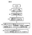
図4は、第1の実施の形態のコンテンツ受信可否報知プログラムを示すフローチャートである。このフローチャートにより、第1の実施の形態の動作を説明する。車載情報端末装置100の制御部101は、情報端末装置100のメインスイッチ(不図示)が投入されるとこのコンテンツ受信可否報知プログラムを実行する。
【0025】
ステップ1において、センターシステム150の管理サーバー153からコンテンツ一覧を取得する。続くステップ2で平均車速Vspを計算する。平均車速としては、過去一定時間の平均車速を用いたり、道路種別が変わった地点からの平均車速を用いることが考えられる。例えば、支線から国道に入ったときは、国道に入った地点を起点として平均車速を計算する。また、国道に入ってから過去一定時間の平均車速を計算してもよい。なお、VICSなどにより進行方向に渋滞や交通規制があるとの交通情報がもたらされた場合には、これらの交通情報を考慮して平均車速を計算するのが望ましい。
【0026】
ステップ3では、通信可否エリアマップ・データベース107から走行道路上の自車位置付近の通信状態データを読み込む。走行中の道路は、GPS受信機103により検出した現在位置を、道路地図データベース106に記憶されている道路地図データと照合して特定する。なお、車両の走行距離と進行方位を検出し、それまでの走行軌跡を道路地図データと照合してマップマッチングを行い、走行中の道路を特定してもよい。
【0027】
続くステップ4で、センターシステム150から入手したコンテンツ一覧の中の各コンテンツに対し、コンテンツサイズS[bit]、平均通信速度m[b/s]、平均車速Vsp[km/h]および走行道路の通信状態に基づいて、コンテンツごとに受信可否を判断する。すなわち、コンテンツサイズS、平均通信速度mおよび平均車速Vspを上記数式1に代入してコンテンツ受信完了までに走行する距離x[m]を計算し、この受信距離xと図2に示すような走行道路の通信状態とに基づいて通信困難な区間に到達するまでにコンテンツを受信できるかどうかを判断する。
【0028】
ステップ5において、コンテンツごとに受信可否判断結果を報知する。ここで、いろいろなコンテンツ受信可否の報知形態について説明する。図5はコンテンツ受信可否の第1の報知形態を示す。この第1の報知形態では、表示装置108のLCD108aの右側にコンテンツ選択表示部201を表示するとともに、LCD108aの左側にナビゲーション画面202を表示する。ナビゲーション画面202では、自車位置周辺の道路地図上に自車位置マーク203を表示している。
【0029】
コンテンツ選択表示部201には、センターシステム150から入手したコンテンツ一覧に含まれる4個のコンテンツが表示される。なお、このコンテンツ表示例では、4個のコンテンツを「content1」、「content2」、「content3」、「content4」というアイコンで表示しているが、これらのアイコンに代えてコンテンツの名称もしくは内容を表す短い文章を表示してもよい。
【0030】
コンテンツの選択は、図6に示すジョグダイヤルスイッチ301によって行う。このジョグダイヤルスイッチ301は入力装置102に含まれる。ジョグダイヤルスイッチ301を回転させると、LCD108aのコンテンツ選択表示部201に表示されたコンテンツ1〜4の中で、フォーカスの当てられたアイコンが順次切り換わる。この例では、「content2」にフォーカスが当たっている状態を示す。ジョグダイヤルスイッチ301を回して受信を希望するコンテンツにフォーカスを当て、ジョグダイヤルスイッチ301を押すとそのコンテンツを選択することができる。
【0031】
走行中には通信状態が時々刻々と変化するため、それによってコンテンツの受信可否も変化する。したがって、運転者がコンテンツの受信要求をする前に、受信不可な状態にあるコンテンツを認識させる必要がある。そこで、上述したコンテンツごとの受信可否判断結果に基づいて、受信不可な状態にあるコンテンツに対しては、コンテンツを選択する際のジョグダイヤルスイッチ301の回転数(操作量)を多くしてそのコンテンツにフォーカスが当たりにくくしてもよい。あるいは、ジョグダイヤルスイッチ301に、回転操作に対する反力を発生させるフォースフィードバックスイッチを設け、受信不可な状態のコンテンツを選択する際に反力を与え、そのコンテンツを選択しにくくしてもよい。これにより、受信不可な状態にあるコンテンツに対して受信を要求する前に、そのコンテンツが受信不可な状態にあることを運転者に知らせることができる。
【0032】
次に、図7により第2の報知形態を説明する。表示装置108のLCD108aの一部にコンテンツ表示部402を設け、コンテンツ1〜4のアイコンを表示するとともに、コンテンツ表示部402の下に各コンテンツアイコンに対応させて入力装置102のコンテンツ選択スイッチ401を配置する。コンテンツ選択スイッチ401にはそれぞれフォースフィードバックスイッチを設け、必要に応じて押圧操作に対する反力を発生させることができる。コンテンツ選択スイッチ401を押圧操作したときに、受信可能なコンテンツの場合は小さな押圧力でスイッチが作動し、受信を要求することができる。一方、受信不可な状態のコンテンツの場合は、大きな押圧力を加えないとスイッチが作動せず、これによりそのコンテンツが受信不可な状態にあることを運転者に知らせることができる。
【0033】
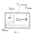
図8により、第3の報知形態を説明する。図8は、表示部108のLCD108aとタッチパネルスイッチ108bによりタッチパネル式操作表示装置501を形成した一例を示す。この例では、コンテンツごとの受信可否状態に応じてコンテンツ選択部の面積を変える。通信状態が良好で受信可能なコンテンツの選択部の面積は広くし、運転者に視認しやすくする。図8の例では、最小サイズの「ニュース情報」コンテンツの通信状態は良好で受信可能であるため、ニュース情報選択部502の面積を広くしている。一方、通信困難で受信不可なコンテンツの選択部の面積は狭くし、運転者に認識しにくくする。図8の例では、最大サイズの「映像情報」コンテンツは通信困難で受信不可であるため、映像情報選択部504の面積を狭くしている。
【0034】
また、通信状態が普通で受信可能なコンテンツの選択部の面積は、通信状態良好なコンテンツ選択部の面積よりも狭く、通信困難なコンテンツ選択部の面積よりも広くし、ある程度の視認性を確保する。図8の例では「天気情報」コンテンツが通信状態が普通で受信可能であり、天気情報選択部503の面積は通信状態良好なニュース情報選択部502より小さく、通信困難な映像情報選択部504よりも大きい。これにより、コンテンツごとの通信状態と受信の可否を瞬時に視認でき、運転操作の妨げになるのを防止できる。
【0035】
なお、図8に示す報知形態では、通信状態が良好で受信可能な「ニュース」コンテンツの選択部502を表示装置501の右側に配置している。すなわち、通信状態が良好で受信可能なコンテンツを、通信状態が普通で受信可能なコンテンツもしくは通信困難で受信不可なコンテンツよりも運転者寄りに表示する。これにより、「ニュース」コンテンツ選択部502が右ハンドル車の運転者に最も近い配置となり、受信要求操作がし易くなる。
【0036】
また、図8に示す報知形態では、通信困難で受信不可な「映像情報」コンテンツに対しても狭いながら選択部504を設けたが、通信状態が良好と普通の受信可能なコンテンツの選択部のみを設けるようにしてもよい。この場合は、表示されているすべてのコンテンツの受信が可能であるから、受信可能か否かを考える必要がなく、さらに視認性がよくなる。
【0037】
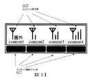
図9により、第4の報知形態を説明する。表示装置108のLCD108aの一部にコンテンツ表示部602を設け、コンテンツの名称と通信状態を表すアイコンを表示するとともに、コンテンツ表示部602の下に各コンテンツに対応させて入力装置102のコンテンツ選択スイッチ601を配置する。コンテンツごとの通信状態を表すアイコンは、携帯電話機などの通信機器に広く用いられている電波状態表示アイコンである。コンテンツ1は通信困難で受信不可であるため、電波状態が圏外のアイコンが表示されている。コンテンツ4は通信状態が良好で受信可能であるため、最も良い電波状態を表すアイコンが表示されている。コンテンツ2と3は通信状態が普通で受信可能であるため、普通の電波状態を表すアイコンが表示されている。このような携帯電話機などの通信機器に広く用いられている電波状態を表すアイコンを用いることによって、コンテンツごとの通信状態と受信の可否を容易に、しかも確実に視認させることができる。
【0038】
なお、上述した報知形態における操作反力や情報選択部の面積は、運転者の嗜好に応じて設定できるのが望ましい。そのため、予め適当な種類の操作反力と情報選択部の面積のサンプル値を記憶装置109に記憶しておき、それらの中から運転者が選択した操作反力と情報選択部の面積を運転者ごとに記憶装置109に記憶するようにしてもよい。
【0039】
このように、基地局からコンテンツ一覧を入手し、コンテンツごとのデータ量、車速、基地局との通信速度、および走行中の道路の通信状態に基づいて、通信困難な地点に達するまでのコンテンツごとの受信可否を判断し、その判断結果を報知するようにしたので、運転中においてもコンテンツごとの受信可否を容易に認識でき、運転操作を妨げることなくコンテンツ受信要求を行うことができる。
【0040】
《発明の第2の実施の形態》
コンテンツ要求時の作業時間を考慮してコンテンツごとの受信可否を判断するようにした第2の実施の形態を説明する。なお、この第2の実施の形態の構成は図1に示す構成と同様であり、説明を省略する。
【0041】
コンテンツ要求時の標準作業時間は、上述したようなコンテンツ選択画面にコンテンツごとの通信状態および受信可否が表示された時点から、受信を要求するコンテンツを決定し、入力装置102またはスイッチ部108bを操作してコンテンツの受信要求を入力し、そのコンテンツの受信が開始されるまでの時間である。この標準作業時間は、運転者の体型、年齢、操作習熟度などの特性、車種などの車載情報端末装置100の操作環境、操作時の運転負荷などにより変化する。
【0042】
ここで、操作者の体型や年齢、操作習熟度といった個人情報による標準作業時間の違いについて考察する。体型と年齢のような個人的なパラメーターは運転時に登録するか、あるいは予め車載情報端末装置100に登録しておく。体型と年齢による標準作業時間をデータベースとして車載情報端末装置100の記憶装置109に記憶しておき、登録されたパラメーターとマッチするデータを読み出す。標準体型に近い運転者はそうでない運転者に比べて操作時の操作負荷量が少なく、標準作業時間が短くなる傾向がある。また、高齢者は若年者に比べて操作判断に要する時間が長いため、標準作業時間が長くなる傾向がある。
【0043】
また、各運転者の操作習熟度の検出方法については、例えば音楽再生などの一連の動作に要する時間や、用意された機能の内のどれだけを使いこなしているか、などにより判断することができる。車載情報端末装置100の合計操作時間が少ない場合は車載情報端末装置100の操作に習熟していると判断でき、一般にコンテンツ要求操作完了までに要する時間は短い。
【0044】
標準作業時間の算出に際しては次のような変形例が考えられる。車種に応じて車載情報端末装置の設置場所が異なり、車載情報端末の配置によって操作の難易度がある。一般に大型車は車室内が広く、運転席から車載情報端末までの距離が遠い傾向があり、小形車は近い傾向がある。したがって、車載情報端末までの距離が近い小型車の方が距離が遠い大型車よりも操作しやすく、小型車に対する標準作業時間を大型車よりも短くする。
【0045】
また、車種によって車載情報端末の操作機器の配置が異なり、それにより標準作業時間が異なる。例えば図10に示すように、ステアリングホイールに車載情報端末装置操作用のハンドルスイッチ701が装着される車両では、未装着車に比べて標準作業時間が短くなる。ステアリングホイールに車載情報端末装置操作用のハンドルスイッチ701が装着される車両では、このハンドルスイッチ701と車載情報端末装置100の前面に設置される入力装置102の操作スイッチ702と2系統の操作機器を備える。このような複数系統の操作機器を装備した車両に対しては、運転者が主にどの操作系を用いているかを検出し、運転者の手元に近いハンドルスイッチ701を用いている場合は操作スイッチ702を用いている場合に比べて標準作業時間を短くする。
【0046】
一方、走行中の運転負荷を考慮して標準作業時間を算出してもよい。運転負荷の大小は、例えば走行中の道路種別や走行速度から判断することができる。直線路が続く高速道路や幹線道路などを一定速度で走行する場合は運転負荷が低い。これに比べて交差点や細街路を走行中は周囲を注視する時間が長く、運転負荷が高い。ブレーキ操作が頻繁に行われる場合、あるいはシフト操作が頻繁に行われる場合には運転負荷が高い状況にあると考えられる。運転負荷が高いほど標準作業時間を長くする。
【0047】
また、低照度環境下では視覚的な判断に要する時間が増加し、標準作業時間が長くなる。運転環境の車外の照度は照度センサーを用いて検出することができる。トンネル通過時など、一時的な照度低下は視覚的な判断に大きな影響を与えるため、日没による照度低下以上に標準作業時間を長くする。
【0048】
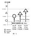
上述した第1の実施の形態の図2および図3で例に上げたサイズS[bit]の異なる3種類のコンテンツA(S=5kB)、B(S=10kB)、C(S=15kB)を走行中に受信する場合の距離を、平均通信速度m=9600[b/s]、車速Vsp=10[m/s]、標準作業時間3秒として計算した例を図11に示す。車速Vspが10[m/s]のときは、車両は3秒間で30m進む。0m地点において、コンテンツ受信要求を決定して操作を開始した場合に、標準作業時間3秒後の30m地点からセンターシステム150との通信が開始され、コンテンツA、B、Cの受信が開始される。
【0049】
S=5kBのコンテンツAは、30m地点から41.7m走った71.7m地点で受信が完了する。同様に、S=10kBのコンテンツBは、30m地点から83.3m走った113.3m地点で受信が完了する。また、S=15kBのコンテンツCは、30m地点から125m走った155m地点で受信が完了する。この走行道路における通信状態は図3に示す状態と同じであるとすると、コンテンツAは通信状態が良好な100m地点までの間に受信を完了するから、コンテンツAの通信状態は良好で受信可能である。また、コンテンツBは通信状態が良好な100m地点までには受信完了しないが、通信状態が普通の200m地点までには受信が完了するので、コンテンツBの通信状態は普通で受信可能である。さらに、コンテンツCも同様に、通信状態が普通の200m地点までには受信が完了するので、コンテンツCの通信状態は普通で受信可能である。
【0050】
図12は、第2の実施の形態のコンテンツ受信可否報知プログラムを示すフローチャートである。このフローチャートにより、第2の実施の形態の動作を説明する。車載情報端末装置100の制御部101は、情報端末装置100のメインスイッチ(不図示)が投入されるとこのコンテンツ受信可否報知プログラムを実行する。
【0051】
ステップ11において、センターシステム150の管理サーバー153からコンテンツ一覧を取得する。続くステップ12で平均車速Vspを計算する。平均車速の計算方法は第1の実施の形態の上述した計算方法と同様である。ステップ13では、上述したように標準作業時間を計算する。ステップ14では、通信可否エリアマップ・データベース107から走行道路上の自車位置付近の通信状態データを読み込む。
【0052】
ステップ15において、センターシステム150から入手したコンテンツ一覧の中の各コンテンツに対し、コンテンツサイズS[bit]、平均通信速度m[b/s]、平均車速Vsp[km/h]、走行道路の通信状態、および上述した標準作業時間に基づいて通信困難な区間に到達するまでにコンテンツを受信できるかどうかを判断する。そして、上述した報知形態によりコンテンツごとに受信可否判断結果を報知する。
【0053】
このように、上述したコンテンツごとの受信可否の判断に際して、運転者が操作部材により受信要求コンテンツを選択し、そのコンテンツの受信が開始されるまでの運転者の標準作業時間を考慮するようにしたので、第1の実施の形態の上述した効果に加え、コンテンツごとの受信可否を正確に判定することができる。
【0054】
特許請求の範囲の構成要素と一実施の形態の構成要素との対応関係は次の通りである。すなわち、携帯電話機101が通信手段を、車速センサー104が車速検出手段を、マイクロコンピューター105が道路特定手段、受信可否判定手段、操作感制御手段および運転負荷検出手段を、通信可否エリアマップ・データベース107が記憶手段を、入力装置102および表示装置108が報知手段を、LCD108aが表示手段を、入力装置102およびスイッチ部108bが操作部材を、フォースフィードバックスイッチ(不図示)が操作反力可変手段をそれぞれ構成する。なお、本発明の特徴的な機能を損なわない限り、各構成要素は上記構成に限定されるものではない。
【図面の簡単な説明】
【図1】 一実施の形態の構成を示す図である。
【図2】 走行道路の通信状態の一例を示す図である。
【図3】 コンテンツごとの受信距離の計算結果を示す図である。
【図4】 第1の実施の形態のコンテンツ受信可否報知プログラムを示すフローチャートである。
【図5】 コンテンツ受信可否の第1の報知形態を示す図である。
【図6】 ジョグダイヤルスイッチを示す図である。
【図7】 コンテンツ受信可否の第2の報知形態を示す図である。
【図8】 コンテンツ受信可否の第3の報知形態を示す図である。
【図9】 コンテンツ受信可否の第4の報知形態を示す図である。
【図10】 車載情報端末装置のハンドルスイッチを示す図である。
【図11】 標準作業時間を考慮した場合のコンテンツごとの受信距離の計算結果を示す図である。
【図12】 第2の実施の形態のコンテンツ受信可否報知プログラムを示すフローチャートである。
【符号の説明】
100 車載情報端末装置
101 携帯電話機
102 入力装置
103 GPS受信機
104 車速センサー
105 マイクロコンピューター
105a CPU
105b ROM
105c RAM
105d A/Dコンバーター
106 道路地図データベース
107 通信可否エリアマップ・データベース
108 表示装置
108a LCD
108b スイッチ部
109 記憶装置
201 コンテンツ選択表示部
202 ナビゲーション画面
301 ジョグダイヤルスイッチ
401 コンテンツ選択スイッチ
402 コンテンツ表示部
501 タッチパネル式操作表示装置
502 ニュース情報選択部
503 天気情報選択部
504 映像情報選択部
601 コンテンツ選択スイッチ
602 コンテンツ表示部
701 ハンドルスイッチ
702 車載情報端末装置スイッチ[0001]
BACKGROUND OF THE INVENTION
The present invention relates to an apparatus for notifying whether information can be received in an information terminal apparatus of a mobile communication system.
[0002]
[Prior art]
Mobile data communication time information that notifies passengers of the time until data communication becomes impossible and the next time it becomes possible when data is obtained by a mobile communication system using a mobile phone or the like A providing system is known (see, for example, Patent Document 1).
[0003]
Prior art documents related to the invention of this application include the following.
[Patent Document 1]
JP 2002-101035 A
[0004]
[Problems to be solved by the invention]
However, the above-described conventional apparatus simply displays a time zone during which communication is disabled from now on, so the reception time is calculated from the amount of information desired to be received until the displayed communication is disabled. There is a problem that it is too complicated as a process to be performed during driving of the vehicle because it is necessary to determine whether or not reception is possible by comparing with time.
[0005]
The present invention provides an information reception availability notification device for mobile communication that enables easy recognition of information reception availability.
[0006]
[Means for Solving the Problems]
The present invention obtains a content list from the base station, and determines the content until reaching a point where communication is difficult based on the data amount for each content, the vehicle speed, the communication speed with the base station, and the communication state of the road on the road. To determine whether or not to receive the notification, and notify the determination resultSometimes, a selection operation feeling is set in accordance with a result of receiving / non-reception determination for each content when a content selection operation is performed by an operation member. , That is.
[0007]
【The invention's effect】
According to the present invention, it is possible to easily recognize whether or not each content can be received even during driving, and it is possible to make a content reception request without disturbing the driving operation.
[0008]
DETAILED DESCRIPTION OF THE INVENTION
An embodiment in which the information reception availability notification device of the present invention is applied to a mobile communication system that performs road-to-vehicle communication between a base station and an in-vehicle information terminal will be described.
[0009]
<< First Embodiment of the Invention >>
FIG. 1 shows a configuration of a mobile communication system according to the first embodiment. This mobile communication system includes an
[0010]
The in-vehicle
[0011]
The
[0012]
The communication availability
[0013]
The
[0014]
The
[0015]
In this embodiment, the in-vehicle
[0016]
The
[0017]
Here, the communication availability area map will be described. In this embodiment, the communication state is evaluated in three stages: good, normal, and difficult. Based on the success and failure of communication with the
[0018]
The communication state for each predetermined section of these traveling roads is stored in the communication availability
[0019]
FIG. 2 shows a communication state along a certain road stored in the communicability
[0020]
In addition, although the example shown in FIG. 2 shows the communication state for every 100 m section on the road, it is not necessary to detect and store the communication state for each predetermined distance section, and the communication state is good, normal, or difficult. What is necessary is just to detect and memorize | store the point which switches to the state, and the communication state after the point.
[0021]
Next, a method for determining whether or not reception is possible for each content will be described. In an environment where communication is performed while moving, it is assumed that the communication state is good when it is predicted that the communication state does not deteriorate from the request for the content until the reception is completed. In this case, the requested content can be received. Further, if it takes time to finish receiving the requested content, for example, partially through a place where the communication state is poor, it is assumed that the communication state is normal. Also in this case, the requested content can be received. On the other hand, when it is expected that the communication will be disconnected in the middle, it is assumed that the communication state is difficult. In this case, the requested content cannot be received.
[0022]
The distance x [m] that the vehicle travels from the content request to the reception completion is the content size (data amount) S [bit], the vehicle speed Vsp [m / s] at the time of the content request, and the average communication speed m [b / s] is obtained by the following equation.
[Expression 1]
x = Vsp · S / m
[0023]
Here, the distance when three types of contents A (S = 5 kB), B (S = 10 kB), and C (S = 15 kB) of different sizes are received while traveling is expressed as an average communication speed m = 9600 [b / s] and vehicle speed Vsp = 10 [m / s] As shown in FIG. 3, the content A is 41.7 m, the content B is 83.3 m, and the content C is 125 m. Among these three types of contents, since A and B can complete reception from the 0 m point to the 100 m point where the communication state is good, the communication state of these A and B contents is good. On the other hand, since the content C cannot be received by the 100 m point where the communication state is good and the reception is completed between the normal 100 m point and the 200 m point where the communication state is normal, the communication state of the content C is normal.
[0024]
FIG. 4 is a flowchart illustrating the content reception availability notification program according to the first embodiment. The operation of the first embodiment will be described with reference to this flowchart. When the main switch (not shown) of the
[0025]
In
[0026]
In
[0027]
In subsequent step 4, for each content in the content list obtained from the
[0028]
In step 5, the reception permission / inhibition determination result is notified for each content. Here, various notification forms of whether or not content can be received will be described. FIG. 5 shows a first notification form of whether or not content can be received. In the first notification form, the content
[0029]
The content
[0030]
The content is selected by the
[0031]
Since the communication state changes from moment to moment while traveling, whether or not content can be received also changes accordingly. Therefore, before the driver makes a content reception request, it is necessary to make the content in a state incapable of reception recognized. Therefore, based on the above-described determination result for each content, for the content in a state where reception is not possible, the number of rotations (operation amount) of the
[0032]
Next, a second notification form will be described with reference to FIG. A
[0033]
A third notification form will be described with reference to FIG. FIG. 8 shows an example in which a touch panel type
[0034]
In addition, the area of the content selection section that can be received when the communication state is normal is narrower than the area of the content selection section that has a good communication state, and wider than the area of the content selection section that is difficult to communicate to ensure a certain degree of visibility. To do. In the example of FIG. 8, the “weather information” content can be received when the communication state is normal, and the area of the weather
[0035]
In the notification form shown in FIG. 8, a “news”
[0036]
In addition, in the notification form shown in FIG. 8, the
[0037]
The fourth notification form will be described with reference to FIG. A
[0038]
In addition, it is desirable that the operation reaction force and the area of the information selection unit in the notification mode described above can be set according to the driver's preference. Therefore, an appropriate type of operation reaction force and a sample value of the area of the information selection unit are stored in the
[0039]
In this way, the content list is obtained from the base station, and the content until reaching the point where communication is difficult is determined based on the data amount for each content, the vehicle speed, the communication speed with the base station, and the communication state of the road on the road. Since it is determined whether or not to be received and the determination result is notified, it is possible to easily recognize whether or not each content can be received even during driving, and it is possible to make a content reception request without interfering with the driving operation.
[0040]
<< Second Embodiment of the Invention >>
A second embodiment will be described in which it is determined whether or not each content can be received in consideration of the work time when the content is requested. The configuration of the second embodiment is the same as the configuration shown in FIG.
[0041]
The standard work time at the time of content request is determined from the content selection screen as described above when the communication status and reception availability for each content are displayed, and the content requested to be received is determined, and the
[0042]
Here, the difference in the standard work time depending on personal information such as the operator's body shape, age, and operation proficiency will be considered. Personal parameters such as body shape and age are registered at the time of driving or previously registered in the in-vehicle
[0043]
In addition, the method for detecting the operation proficiency level of each driver can be determined by, for example, the time required for a series of operations such as music playback, and how much of the prepared functions are used. When the total operation time of the in-vehicle
[0044]
In calculating the standard work time, the following modifications can be considered. The installation location of the in-vehicle information terminal device differs depending on the vehicle type, and the operation is difficult depending on the arrangement of the in-vehicle information terminal. In general, large vehicles have a large passenger compartment, and the distance from the driver's seat to the in-vehicle information terminal tends to be long, and small vehicles tend to be close. Therefore, a small vehicle with a short distance to the in-vehicle information terminal is easier to operate than a large vehicle with a long distance, and the standard work time for the small vehicle is shorter than that of the large vehicle.
[0045]
In addition, the arrangement of the operating devices of the in-vehicle information terminal differs depending on the vehicle type, and the standard work time varies accordingly. For example, as shown in FIG. 10, in a vehicle in which a steering wheel is mounted with a
[0046]
On the other hand, the standard work time may be calculated in consideration of the driving load during traveling. The magnitude of the driving load can be determined from, for example, the type of road that is running and the running speed. When driving at a constant speed on a highway or a main road that is followed by a straight road, the driving load is low. Compared to this, while traveling on intersections and narrow streets, it takes longer to watch the surroundings and the driving load is high. When the brake operation is frequently performed or when the shift operation is frequently performed, it is considered that the driving load is high. The standard working time is lengthened as the operating load increases.
[0047]
Further, in a low light environment, the time required for visual judgment increases and the standard work time becomes longer. Illuminance outside the vehicle in the driving environment can be detected using an illuminance sensor. Temporary decline in illuminance, such as when passing through a tunnel, has a significant effect on visual judgment.
[0048]
Two types of contents A (S = 5 kB), B (S = 10 kB), and C (S = 15 kB) having different sizes S [bit], which are exemplified in FIGS. 2 and 3 of the first embodiment described above. FIG. 11 shows an example in which the distance when the vehicle is received while traveling is calculated as an average communication speed m = 9600 [b / s], a vehicle speed Vsp = 10 [m / s], and a standard work time of 3 seconds. When the vehicle speed Vsp is 10 [m / s], the vehicle travels 30 m in 3 seconds. When the content reception request is determined and the operation is started at the 0m point, communication with the
[0049]
The reception of the content A of S = 5 kB is completed at the 71.7 m point that has run 41.7 m from the 30 m point. Similarly, reception of the content B of S = 10 kB is completed at the 113.3 m point that has run 83.3 m from the 30 m point. Also, the reception of the content C of S = 15 kB is completed at the 155 m point that has run 125 m from the 30 m point. If the communication state on this road is the same as the state shown in FIG. 3, the content A is completely received up to the 100 m point where the communication state is good. is there. Further, although the content B is not completely received by the 100 m point where the communication state is good, the reception is completed by the 200 m point where the communication state is normal, so that the communication state of the content B is normal and can be received. Further, similarly, since the reception of the content C is completed up to the 200 m point where the communication state is normal, the communication state of the content C can be received normally.
[0050]
FIG. 12 is a flowchart illustrating a content reception availability notification program according to the second embodiment. The operation of the second embodiment will be described with reference to this flowchart. When the main switch (not shown) of the
[0051]
In
[0052]
In
[0053]
As described above, when determining whether or not each content can be received, the standard operation time of the driver until the driver selects the reception request content by the operation member and the reception of the content is started is considered. Therefore, in addition to the above-described effects of the first embodiment, it is possible to accurately determine whether or not each content can be received.
[0054]
The correspondence between the constituent elements of the claims and the constituent elements of the embodiment is as follows. That is, the
[Brief description of the drawings]
FIG. 1 is a diagram showing a configuration of an embodiment.
FIG. 2 is a diagram illustrating an example of a communication state of a traveling road.
FIG. 3 is a diagram illustrating a calculation result of a reception distance for each content.
FIG. 4 is a flowchart illustrating a content reception availability notification program according to the first embodiment.
FIG. 5 is a diagram showing a first notification form of whether or not content can be received.
FIG. 6 is a diagram showing a jog dial switch.
[Fig. 7] Fig. 7 is a diagram showing a second notification form of whether or not content can be received.
[Fig. 8] Fig. 8 is a diagram showing a third notification form of whether or not content can be received.
FIG. 9 is a diagram showing a fourth notification form for determining whether or not content can be received;
FIG. 10 is a diagram showing a handle switch of the in-vehicle information terminal device.
FIG. 11 is a diagram illustrating a calculation result of a reception distance for each content in consideration of a standard work time.
FIG. 12 is a flowchart illustrating a content reception availability notification program according to the second embodiment.
[Explanation of symbols]
100 In-vehicle information terminal device
101 Mobile phone
102 Input device
103 GPS receiver
104 Vehicle speed sensor
105 Microcomputer
105a CPU
105b ROM
105c RAM
105d A / D converter
106 Road map database
107 Communication availability area map database
108 Display device
108a LCD
108b Switch part
109 storage device
201 Content selection display section
202 Navigation screen
301 Jog dial switch
401 Content selection switch
402 Content display section
501 Touch panel operation display device
502 News information selection section
503 Weather information selection part
504 Video information selection section
601 Content selection switch
602 content display section
701 Handle switch
702 On-vehicle information terminal switch
Claims (21)
Translated fromJapanese車速を検出する車速検出手段と、
走行中の道路を特定する道路特定手段と、
自車または他車が走行した道路の通信状態を記憶する記憶手段と、
前記通信手段を介して基地局からコンテンツ一覧を入手し、コンテンツごとのデータ量、現在の車速、前記通信手段の通信速度および前記道路特定手段により特定された走行中の道路の通信状態に基づいて、通信困難な地点に達するまでのコンテンツごとの受信可否を判定する受信可否判定手段と、
コンテンツごとの受信可否の判定結果を報知する報知手段とを備えた移動体通信の情報受信可否報知装置であって、
前記報知手段は、コンテンツ一覧を表示する表示手段と、コンテンツを選択する操作部材とを有し、
前記操作部材によるコンテンツの選択操作に際して、前記受信可否判定手段によるコンテンツごとの受信可否判定結果に応じて選択操作感を設定する操作感制御手段とを備えることを特徴とする移動体通信の情報受信可否報知装置。A communication means for performing wireless communication with a base station outside the passenger compartment;
Vehicle speed detection means for detecting the vehicle speed;
Road identification means for identifying the road on which it is traveling;
Storage means for storing a communication state of a road on which the vehicle or another vehicle has traveled;
Obtain a content list from the base station via the communication means, and based on the amount of data for each content, the current vehicle speed, the communication speed of the communication means, and the communication state of the running road specified by the road specifying means A reception availability determination means for determining whether or not each content can be received until reaching a point where communication is difficult;
An information reception availability notification device for mobile communication comprising notification means for notifying a determination result of reception availability for each content,
The notification means includes display means for displaying a content list, and an operation member for selecting content,
Mobile communication information reception, comprising:an operation feeling control unit that sets a selection operation feeling according to a reception availability determination result for each content by the reception availability determination unit when the content is selected by the operation member. Availability notification device.
前記操作感制御手段は、受信不可なコンテンツに対してはそのコンテンツが選択しにくくなるように選択操作感を設定することを特徴とする移動体通信の情報受信可否報知装置。In the mobile communication information reception availability notification device according to claim 1,
The operation feeling control means sets a selection operation feeling so that it is difficult to select content that cannot be received .
前記操作感制御手段は、受信不可なコンテンツの選択操作に対しては前記操作部材の操作量を多くすることを特徴とする移動体通信の情報受信可否報知装置。In the mobile communication information reception availability notification device according to claim 2,
The operation feeling control means, not ready content for mobile communication of information receivability notification device, characterized in thatto increase the operation amount of the operation member for the selecting operation.
前記操作部材に操作反力可変手段を設け、
前記操作感制御手段は、受信不可なコンテンツの選択操作に対しては前記操作反力可変手段により前記操作部材の操作反力を大きくすることを特徴とする移動体通信の情報受信可否報知装置。In the mobile communication information reception availability notification device according to claim2 ,
An operation reaction force variable means is provided on the operation member,
The operation feeling control means increases an operation reaction force of the operation member by the operation reaction force variable means for a selection operation of a content that cannot be received, and is an information reception availability notification device for mobile communication.
前記操作感制御手段の選択操作感を運転者が手動で任意に調整可能とすることを特徴とする移動体通信の情報受信可否報知装置。In the mobile communication information reception availability notification device according to claim2 ,
An information reception availability notification device for mobile communication,wherein a driver can manually adjust a selection operation feeling of the operation feeling control means .
前記受信可否判定手段によるコンテンツごとの受信可否判定結果に応じて、前記表示手段のコンテンツ一覧表示におけるコンテンツごとの表示状態を設定する表示制御手段を備えることを特徴とする移動体通信の情報受信可否報知装置。In the mobile communication information reception availability notification device according to claim1 ,
Mobile communication information reception availability, comprising: a display control unit that sets a display state for each content in the content list display of the display unit according to a reception availability determination result for each content by the reception availability determination unit. Notification device.
前記表示制御手段は、受信可能なコンテンツを受信不可なコンテンツよりも大きく表示することを特徴とする移動体通信の情報受信可否報知装置。In the mobile communication information reception availability notification device according to claim6 ,
Wherein the display control unit, a mobile communication information receivability notificationapparatus characterized bylarge display than unreceivable content receivable contents.
前記表示制御手段は、受信不可なコンテンツを表示しないことを特徴とする移動体通信の情報受信可否報知装置。In the mobile communication information reception availability notification device according to claim6 ,
The display control means does not display unreceivable content, and is a mobile communication information reception availability notification device.
前記表示制御手段は、受信可能なコンテンツを受信不可なコンテンツよりも運転者寄りに表示することを特徴とする移動体通信の情報受信可否報知装置。In the mobile communication information reception availability notification device according to claim6 ,
Wherein the display control unit, a mobile communication information receivability notification apparatus anddisplaying the receivable contents to the driver nearer unreceivable content.
前記表示制御手段は、携帯電話機の電波状態表示アイコンによりコンテンツごとの受信可否判定結果を表示することを特徴とする移動体通信の情報受信可否報知装置。In the mobile communication information reception availability notification device according to claim6 ,
The mobile communication information reception availability notification device, wherein the display control means displays a reception availability determination result for each content by a radio wave state display icon of a mobile phone .
前記表示制御手段の表示状態を任意に調整可能とすることを特徴とする移動体通信の情報受信可否報知装置。In the mobile communication information reception availability notification device according to claim6 ,
An information reception availability notification device for mobile communication,wherein the display state of the display control means can be arbitrarily adjusted .
前記受信可否判定手段は、運転者が前記操作部材により受信要求コンテンツを選択し、そのコンテンツの受信が開始されるまでの運転者の作業時間を考慮してコンテンツごとの受信可否を判定することを特徴とする移動体通信の情報受信可否報知装置。In the mobile communication information reception availability notification device according to claim1 ,
The reception availability determination means determines whether reception is possible foreach content in consideration of a driver's work time until the driver selects reception requested content by the operation member and reception of the content is started. An information reception availability notification device for mobile communication, which is characterized.
前記受信可否判定手段は、運転者ごとの個人情報に基づいて前記運転者の作業時間を決定することを特徴とする移動体通信の情報受信可否報知装置。The mobile communication information reception availability notification device according to claim12 ,
The reception determination unit, a mobile communication information receivability notificationapparatus characterized bydetermining the working time of the driver based on the personal information for each driver.
前記運転者ごとの個人情報には運転者の年齢が含まれることを特徴とする移動体通信の情報受信可否報知装置。In the mobile communication information reception availability notification device according to claim13 ,
The personal information for each driver includes the age of the driver, and is a mobile communication information reception availability notification device.
前記運転者ごとの個人情報には運転者の操作習熟度が含まれることを特徴とする移動体通信の情報受信可否報知装置。In the mobile communication information reception availability notification device according to claim13 ,
The mobile communication information reception availability notification device,wherein the personal information for each driver includes a driver's operation proficiency level .
前記受信可否判定手段は、車室内における前記操作部材の配置を考慮して前記運転者の作業時間を決定することを特徴とする移動体通信の情報受信可否報知装置。The mobile communication information reception availability notification device according to claim12 ,
The information reception availability notification device for mobile communication characterizedin that thereception availability determination means determines a working time of the driver in consideration of an arrangement of the operation member in a passenger compartment .
前記操作部材は車室内の複数箇所に配置されており、
前記受信可否判定手段は、コンテンツの選択操作に用いられる操作部材が運転者の手元に近いほど前記運転者の作業時間を短くすることを特徴とする移動体通信の情報受信可否報知装置。The mobile communication information reception availability notification device according to claim16 ,
The operating member is disposed at a plurality of locations in the passenger compartment,
The information reception availability notification device of mobile communication characterizedin that thereception availability determination means shortens the operation time of the driver as an operation member used for content selection operation is closer to the driver .
運転負荷を検出する運転負荷検出手段を備え、
前記受信可否判定手段は、前記運転負荷検出手段により検出された運転負荷に応じて前記運転者の作業時間を決定することを特徴とする移動体通信の情報受信可否報知装置。The mobile communication information reception availability notification device according to claim12 ,
A driving load detection means for detecting the driving load is provided,
The information reception availability notification device for mobile communication,wherein the reception availability determination means determines a working time of the driver according to the driving load detected by the driving load detection means .
前記運転負荷検出手段は、前記道路特定手段により特定された道路の種別に基づいて前記運転負荷を検出することを特徴とする移動体通信の情報受信可否報知装置。The mobile communication information reception availability notification device according to claim18 ,
The information receiving availability notification device for mobile communication,wherein the driving load detecting means detects the driving load based on a type of road specified by the road specifying means .
ブレーキペダルとシフトレバーの操作を検出する運転操作検出手段を備え、
前記運転負荷検出手段は、前記運転操作検出手段により検出されたブレーキペダルとシフトレバーの操作頻度に基づいて前記運転負荷を検出することを特徴とする移動体通信の情報受信可否報知装置。The mobile communication information reception availability notification device according to claim18 ,
Driving operation detection means for detecting the operation of the brake pedal and the shift lever is provided,
The driving load detection means detects the driving load based on the operation frequency of the brake pedal and the shift lever detected by the driving operation detection means .
車外の照度を検出する照度検出手段を備え、
前記運転負荷検出手段は、前記照度検出手段により検出された車外の照度に基づいて前記運転負荷を検出することを特徴とする移動体通信の情報受信可否報知装置。The mobile communication information reception availability notification device according to claim18 ,
With illuminance detection means for detecting the illuminance outside the vehicle,
The information receiving availability notification device for mobile communication characterizedin that thedriving load detecting means detects the driving load based on illuminance outside the vehicle detected by the illuminance detecting means .
Priority Applications (1)
| Application Number | Priority Date | Filing Date | Title |
|---|---|---|---|
| JP2003034892AJP4178984B2 (en) | 2003-02-13 | 2003-02-13 | Information reception availability notification device for mobile communication |
Applications Claiming Priority (1)
| Application Number | Priority Date | Filing Date | Title |
|---|---|---|---|
| JP2003034892AJP4178984B2 (en) | 2003-02-13 | 2003-02-13 | Information reception availability notification device for mobile communication |
Publications (2)
| Publication Number | Publication Date |
|---|---|
| JP2004247907A JP2004247907A (en) | 2004-09-02 |
| JP4178984B2true JP4178984B2 (en) | 2008-11-12 |
Family
ID=33020461
Family Applications (1)
| Application Number | Title | Priority Date | Filing Date |
|---|---|---|---|
| JP2003034892AExpired - Fee RelatedJP4178984B2 (en) | 2003-02-13 | 2003-02-13 | Information reception availability notification device for mobile communication |
Country Status (1)
| Country | Link |
|---|---|
| JP (1) | JP4178984B2 (en) |
Families Citing this family (7)
| Publication number | Priority date | Publication date | Assignee | Title |
|---|---|---|---|---|
| JP2007081714A (en)* | 2005-09-13 | 2007-03-29 | Matsushita Electric Ind Co Ltd | COMMUNICATION TERMINAL DEVICE, ITS CONTROL METHOD, AND MBMS PROVIDING METHOD |
| JP2007174179A (en)* | 2005-12-21 | 2007-07-05 | Kyocera Corp | Mobile communication terminal |
| JP2009093206A (en)* | 2006-02-02 | 2009-04-30 | Panasonic Corp | Communication terminal device and information notification method |
| JP5092672B2 (en)* | 2007-10-11 | 2012-12-05 | 株式会社Jvcケンウッド | Communication terminal, information output control method, and information output control program |
| JP5934045B2 (en)* | 2012-07-13 | 2016-06-15 | 株式会社コナミデジタルエンタテインメント | Terminal device and program |
| KR102017801B1 (en)* | 2017-11-15 | 2019-09-03 | 엘지전자 주식회사 | Vehicle control device mounted on vehicle and method for controlling the vehicle |
| KR102014262B1 (en) | 2017-12-11 | 2019-08-26 | 엘지전자 주식회사 | Display device mounted on vehicle and method for controlling the display device |
- 2003
- 2003-02-13JPJP2003034892Apatent/JP4178984B2/ennot_activeExpired - Fee Related
Also Published As
| Publication number | Publication date |
|---|---|
| JP2004247907A (en) | 2004-09-02 |
Similar Documents
| Publication | Publication Date | Title |
|---|---|---|
| JP4497748B2 (en) | Navigation device, server device for navigation system, destination estimation processing program, and recording medium recording destination estimation processing program | |
| JP5181819B2 (en) | Danger information collection and distribution device | |
| US7099773B2 (en) | Navigation system allowing to remove selected items from route for recalculating new route to destination | |
| JP4935704B2 (en) | Parking lot congestion state determination device, parking lot congestion state determination method, and computer program | |
| JP4581564B2 (en) | Map display device | |
| US7957896B2 (en) | Vehicular display system and method | |
| JPWO2003040654A1 (en) | Vehicle navigation apparatus and program | |
| JP2008196923A (en) | Map display apparatus for vehicle | |
| JP4380249B2 (en) | Vehicle information provision system | |
| JP2010185333A (en) | On vehicle information processor, method and program for controlling on vehicle information processor | |
| JP4830725B2 (en) | Route guidance device | |
| US20090237413A1 (en) | Screen formation system, screen formation method, and program | |
| JP4687575B2 (en) | Car navigation system | |
| JP4178984B2 (en) | Information reception availability notification device for mobile communication | |
| JP2010101709A (en) | Navigation apparatus, and method and program for controlling the same | |
| JP2005292052A (en) | On-vehicle navigation system | |
| JP2000003497A (en) | Travel position display device | |
| JP3344450B2 (en) | Vehicle navigation system | |
| CN115143986B (en) | Navigation device, navigation system, and route guidance method | |
| JP7464546B2 (en) | Map Display System | |
| JP4097553B2 (en) | Navigation device | |
| JP3534387B2 (en) | Point setting operation display guidance device by map | |
| JP2011033402A (en) | Apparatus and method for guidance of congestion degree, and computer program | |
| JP4970181B2 (en) | In-vehicle information terminal, control method thereof, and control program thereof | |
| US7660664B2 (en) | Information service system |
Legal Events
| Date | Code | Title | Description |
|---|---|---|---|
| A621 | Written request for application examination | Free format text:JAPANESE INTERMEDIATE CODE: A621 Effective date:20051226 | |
| A977 | Report on retrieval | Free format text:JAPANESE INTERMEDIATE CODE: A971007 Effective date:20071112 | |
| A131 | Notification of reasons for refusal | Free format text:JAPANESE INTERMEDIATE CODE: A131 Effective date:20080325 | |
| A521 | Request for written amendment filed | Free format text:JAPANESE INTERMEDIATE CODE: A523 Effective date:20080519 | |
| TRDD | Decision of grant or rejection written | ||
| A01 | Written decision to grant a patent or to grant a registration (utility model) | Free format text:JAPANESE INTERMEDIATE CODE: A01 Effective date:20080805 | |
| A01 | Written decision to grant a patent or to grant a registration (utility model) | Free format text:JAPANESE INTERMEDIATE CODE: A01 | |
| A61 | First payment of annual fees (during grant procedure) | Free format text:JAPANESE INTERMEDIATE CODE: A61 Effective date:20080818 | |
| R150 | Certificate of patent or registration of utility model | Ref document number:4178984 Country of ref document:JP Free format text:JAPANESE INTERMEDIATE CODE: R150 Free format text:JAPANESE INTERMEDIATE CODE: R150 | |
| FPAY | Renewal fee payment (event date is renewal date of database) | Free format text:PAYMENT UNTIL: 20110905 Year of fee payment:3 | |
| FPAY | Renewal fee payment (event date is renewal date of database) | Free format text:PAYMENT UNTIL: 20120905 Year of fee payment:4 | |
| FPAY | Renewal fee payment (event date is renewal date of database) | Free format text:PAYMENT UNTIL: 20120905 Year of fee payment:4 | |
| FPAY | Renewal fee payment (event date is renewal date of database) | Free format text:PAYMENT UNTIL: 20130905 Year of fee payment:5 | |
| LAPS | Cancellation because of no payment of annual fees |