JP4178134B2 - Method of joining an iron-based alloy member and an aluminum-based alloy member - Google Patents
Method of joining an iron-based alloy member and an aluminum-based alloy memberDownload PDFInfo
- Publication number
- JP4178134B2 JP4178134B2JP2004213426AJP2004213426AJP4178134B2JP 4178134 B2JP4178134 B2JP 4178134B2JP 2004213426 AJP2004213426 AJP 2004213426AJP 2004213426 AJP2004213426 AJP 2004213426AJP 4178134 B2JP4178134 B2JP 4178134B2
- Authority
- JP
- Japan
- Prior art keywords
- aluminum
- based alloy
- iron
- alloy member
- welding
- Prior art date
- Legal status (The legal status is an assumption and is not a legal conclusion. Google has not performed a legal analysis and makes no representation as to the accuracy of the status listed.)
- Expired - Fee Related
Links
- XEEYBQQBJWHFJM-UHFFFAOYSA-NIronChemical compound[Fe]XEEYBQQBJWHFJM-UHFFFAOYSA-N0.000titleclaimsdescription102
- 229910052782aluminiumInorganic materials0.000titleclaimsdescription73
- XAGFODPZIPBFFR-UHFFFAOYSA-NaluminiumChemical compound[Al]XAGFODPZIPBFFR-UHFFFAOYSA-N0.000titleclaimsdescription70
- 229910052742ironInorganic materials0.000titleclaimsdescription48
- 229910045601alloyInorganic materials0.000titleclaimsdescription37
- 239000000956alloySubstances0.000titleclaimsdescription37
- 238000000034methodMethods0.000titleclaimsdescription35
- 238000005304joiningMethods0.000titleclaimsdescription33
- 238000003466weldingMethods0.000claimsdescription46
- 229910052751metalInorganic materials0.000claimsdescription12
- 239000002184metalSubstances0.000claimsdescription12
- 238000007712rapid solidificationMethods0.000claimsdescription10
- 238000001816coolingMethods0.000claimsdescription5
- 238000004519manufacturing processMethods0.000claimsdescription3
- 230000001678irradiating effectEffects0.000claimsdescription2
- 239000012071phaseSubstances0.000description36
- 229910000831SteelInorganic materials0.000description17
- 239000010959steelSubstances0.000description17
- 239000000463materialSubstances0.000description16
- 239000006104solid solutionSubstances0.000description16
- 229910000765intermetallicInorganic materials0.000description9
- 239000010935stainless steelSubstances0.000description8
- 229910001220stainless steelInorganic materials0.000description8
- 238000010586diagramMethods0.000description6
- 238000007711solidificationMethods0.000description5
- PXHVJJICTQNCMI-UHFFFAOYSA-NNickelChemical compound[Ni]PXHVJJICTQNCMI-UHFFFAOYSA-N0.000description4
- 238000004458analytical methodMethods0.000description4
- 238000005219brazingMethods0.000description4
- 239000007787solidSubstances0.000description4
- 239000011324beadSubstances0.000description3
- 150000001875compoundsChemical class0.000description3
- 230000000694effectsEffects0.000description3
- 239000000203mixtureSubstances0.000description3
- 230000035515penetrationEffects0.000description3
- 230000008023solidificationEffects0.000description3
- 238000005211surface analysisMethods0.000description3
- XKRFYHLGVUSROY-UHFFFAOYSA-NArgonChemical compound[Ar]XKRFYHLGVUSROY-UHFFFAOYSA-N0.000description2
- CURLTUGMZLYLDI-UHFFFAOYSA-NCarbon dioxideChemical compoundO=C=OCURLTUGMZLYLDI-UHFFFAOYSA-N0.000description2
- 229910015372FeAlInorganic materials0.000description2
- 238000002441X-ray diffractionMethods0.000description2
- 239000010953base metalSubstances0.000description2
- 230000000052comparative effectEffects0.000description2
- 238000005516engineering processMethods0.000description2
- 238000002844meltingMethods0.000description2
- 230000008018meltingEffects0.000description2
- 150000002739metalsChemical class0.000description2
- 229910052759nickelInorganic materials0.000description2
- 238000000682scanning probe acoustic microscopyMethods0.000description2
- KCZFLPPCFOHPNI-UHFFFAOYSA-Nalumane;ironChemical compound[AlH3].[Fe]KCZFLPPCFOHPNI-UHFFFAOYSA-N0.000description1
- -1and at the joint CChemical compound0.000description1
- 229910052786argonInorganic materials0.000description1
- 230000033228biological regulationEffects0.000description1
- 229910002092carbon dioxideInorganic materials0.000description1
- 239000001569carbon dioxideSubstances0.000description1
- 238000005260corrosionMethods0.000description1
- 230000007797corrosionEffects0.000description1
- 239000013078crystalSubstances0.000description1
- 230000007423decreaseEffects0.000description1
- 230000003247decreasing effectEffects0.000description1
- 238000013461designMethods0.000description1
- 238000011161developmentMethods0.000description1
- 238000009826distributionMethods0.000description1
- 238000010894electron beam technologyMethods0.000description1
- 238000002474experimental methodMethods0.000description1
- 230000004907fluxEffects0.000description1
- 239000000446fuelSubstances0.000description1
- 239000007789gasSubstances0.000description1
- 210000004907glandAnatomy0.000description1
- 230000000762glandularEffects0.000description1
- 239000011521glassSubstances0.000description1
- 230000005484gravityEffects0.000description1
- 238000009957hemmingMethods0.000description1
- 238000009396hybridizationMethods0.000description1
- 238000011835investigationMethods0.000description1
- 238000005259measurementMethods0.000description1
- 238000001000micrographMethods0.000description1
- 238000000465mouldingMethods0.000description1
- 238000003825pressingMethods0.000description1
- 239000000047productSubstances0.000description1
- 239000002994raw materialSubstances0.000description1
- 238000011160researchMethods0.000description1
- 238000004626scanning electron microscopyMethods0.000description1
- 239000007790solid phaseSubstances0.000description1
- 239000000243solutionSubstances0.000description1
- 239000013589supplementSubstances0.000description1
- 238000009864tensile testMethods0.000description1
- 238000012360testing methodMethods0.000description1
Images


Landscapes
- Laser Beam Processing (AREA)
Description
Translated fromJapanese本発明は、鉄系合金部材とアルミニウム系合金部材を溶接により接合して得られる接合体の製造方法に関し、特にその溶接部の接合強度に優れた異種金属溶接接合体の接合方法に関するものである。The present invention relates to amethod formanufacturing a joined body obtained by joining an iron-based alloy member and an aluminum-based alloy member by welding, and particularly relates toa joining method for dissimilar metal welded joints having excellent joint strength at the welded portion. .
近年、排ガス規制など地球環境改善のため、車の軽量化による燃費改善が強く求められている。 In recent years, in order to improve the global environment such as exhaust gas regulations, there has been a strong demand for improved fuel consumption by reducing the weight of vehicles.
アルミニウム(以下、アルミと略称することがある)は鋼と比べて比重が約三分の一と軽く、耐食性がよく、複雑形状の素材でも押出工法により比較的簡単に得られることと、アルミの材料特性とが相まってクラッシャブル性に優れているなどの特長を有しているため、車の軽量化に望ましい金属である。反面、鋼と比べてアルミは剛性および強度と材料コスト面で劣る。 Aluminum (hereinafter sometimes abbreviated as “aluminum”) has a specific gravity that is about one-third lighter than steel, and has good corrosion resistance. It is a desirable metal for reducing the weight of a car because it has features such as excellent crushability combined with material properties. On the other hand, aluminum is inferior in rigidity, strength and material cost compared to steel.
従って、車の構成部品を鋼とアルミの各々の利点を活して使い分けてハイブリット化できれば、車の軽量化だけでなくリサイクル性、車の安全性向上にもつながる。 Therefore, if the components of the car can be hybridized by making the best use of the advantages of steel and aluminum, not only the weight of the car but also the recyclability and the safety of the car can be improved.
この鋼とアルミを併用するハイブリット化に当たっては、鋼とアルミの部品毎の具体的な使い分けやそれらの材料設計が重要となることはもちろんだが、両材料の接合技術が必須となる。 For hybridization using both steel and aluminum, it is important to use steel and aluminum in specific parts and material design, but it is essential to join both materials.
ところが、鉄系合金とアルミ系合金を溶接により溶解にして直接接合すると脆い金属間化合物が生成し、そのため十分な接合強度が得られず、実用化が極めて難しかった。このためこの溶接法に代えてカニカル接合法、ロー付け法、摩擦圧接法及びインサート材による接合工法が実用化されてきた。 However, when an iron-based alloy and an aluminum-based alloy are dissolved and welded directly to each other, a brittle intermetallic compound is generated, so that a sufficient joint strength cannot be obtained and it is extremely difficult to put it to practical use. For this reason, instead of this welding method, a canonical joining method, a brazing method, a friction welding method, and a joining method using an insert material have been put into practical use.
しかし、これらの接合技術はいずれも一長一短があり、特に以下のような不利や問題を有しており、いまだ十分に満足できる接合法とはいえない状況にある。
(メカニカル接合法)
ボルト接合、リベット接合、ネジ接合、メカニカルクリンチ、ヘミング、メカニカル成形接合など、部材同士を機械的に接合する方法である。しかし、この方法は、接合部品の形状制約、接合精度、生産性、及び汎用性などの面で同質材料(鋼同士など)の溶接より一般的に劣る。
(ロー付け法)
部材同士を媒介となるロー材を溶かして接合する方法である。この方法は鋼とアルミの接合法としても提案(特許文献1など)されてはいるが、フラックスにより鋼、アルミの酸化皮膜を除去し、母材を溶解することなく、両金属の活性面とロー材とで適切な化合物を生成することが必要になる。この適切な化合物を得るためロー材の材料、接合品の材質・形状、接合強度、接合品質の信頼性に制約が付される。従って、接合の作業性、生産性、汎用性はやはり、同質材料(鋼同士など)の溶接より一般的に不利を伴う。
(摩擦圧接法)
部材同志を加圧しながら回転させ、その際の摺動に伴う摩擦熱を利用した固相接合である。しかし、この方法は加圧回転が必要なことから接合部品に形状制約があり、接合で生じるバリの処理が必要なこと、ビート゛溶接のような長手方向の溶接が難しいことやMg含有合金(5000系)の場合は酸化物(MgO)の発生により溶接が困難になるなど作業性、汎用性、生産性の面でやはり同質材料(鋼同士など)の溶接より一般的に劣る。
(インサート材接合法)
部材同志間にクラッド材をインサートしてスポット溶接などによって接合する方法である。しかし、この方法はクラッド材のインサートに伴う部品形状に制約が付されることと、作業性に劣ることおよびコスト面の課題を有し、やはり同質材料(鋼同士など)の溶接より一般的に劣るものである。
(Mechanical joining method)
This is a method of mechanically joining members together such as bolt joining, rivet joining, screw joining, mechanical clinch, hemming, and mechanical molding joining. However, this method is generally inferior to welding of homogeneous materials (such as steels) in terms of shape constraints, joining accuracy, productivity, and versatility of joined parts.
(Brazing method)
In this method, the brazing material that serves as a medium between members is melted and joined. Although this method has also been proposed as a method for joining steel and aluminum (
(Friction welding method)
This is a solid phase bonding that uses frictional heat generated by sliding the members while rotating the members while applying pressure. However, since this method requires pressurization and rotation, there are restrictions on the shape of the joined parts, the treatment of burrs generated in the joining is necessary, longitudinal welding such as beat welding is difficult, and Mg-containing alloys (5000 In the case of the system), it is generally inferior to welding of homogeneous materials (such as steel) in terms of workability, versatility, and productivity, such as the difficulty of welding due to the generation of oxide (MgO).
(Insert material joining method)
In this method, a clad material is inserted between members and joined by spot welding or the like. However, this method has restrictions on the part shape associated with the insert of the clad material, inferior workability and cost problems, and is generally more common than welding of homogeneous materials (such as steel). It is inferior.
本発明は、上述した従来の鋼とアルミニウムなど鉄系合金部材とアルミニウム系合金部材の接合技術の背景に鑑み、これらの不利や問題点を全面的に解消し、同質部材同志の溶接と実質的に変わらない優れた接合強度と高い生産性などの利点を享受し得る画期的な異種金属接合体ならびにその接合技術の開発と実用化をその課題としてなされたものである。 In view of the background of the joining technology of the above-described conventional steel and aluminum-based alloy members and aluminum-based alloy members, the present invention completely eliminates these disadvantages and problems, and is substantially equivalent to welding of homogeneous members. The development and commercialization of a revolutionary dissimilar metal joint that can enjoy advantages such as excellent joint strength and high productivity, as well as its joining technology, have been made as its issues.
本発明はこのような課題の解決のために完成されたものであって、その要旨とする特徴は以下の通りである。 The present invention has been completed to solve such a problem, and the gist of the present invention is as follows.
パイプ状の鉄系合金部材とパイプ状または棒状のアルミニウム系合金部材とを溶接により接合して異種金属接合体を製造する方法において、前記鉄系合金部材の内側に前記アルミニウム系合金部材を圧入した状態で、鉄系合金部材側から10In the method of manufacturing a dissimilar metal joined body by welding a pipe-shaped iron-based alloy member and a pipe-shaped or rod-shaped aluminum-based alloy member, the aluminum-based alloy member is press-fitted inside the iron-based alloy member. 10 from the iron-based alloy member side66W/cmW / cm22以上の入熱密度のレーザーを照射、入熱して鉄系合金部材を溶解させるとともにその一部をアルミニウム系合金部材に喰い込ませるようにしてアルミニウム系合金部材を溶解して両者を溶接した後、10K/s以上の冷却速度で急冷凝固させ、これによって鉄系合金部材の再凝固相(A)とアルミニウム系合金部材の再凝固相(B)の境界相として形成される溶接接合部(C)が鉄にアルミニウムが4〜50原子%過飽和に固溶した組織とする異種金属接合体を得ることを特徴とする鉄系合金部材とアルミニウム系合金部材の接合方法。After irradiating the laser with the above heat input density, applying heat to dissolve the iron-based alloy member and partly engulfing the aluminum-based alloy member to melt the aluminum-based alloy member and welding both, A welded joint (C) formed as a boundary phase between the resolidification phase (A) of the iron-based alloy member and the resolidification phase (B) of the aluminum-based alloy member by rapid solidification at a cooling rate of 10 K / s or more. A method for joining an iron-based alloy member and an aluminum-based alloy member, characterized in that a dissimilar metal joined body having a structure in which aluminum is solid-solved in a supersaturated state of 4 to 50 atomic% in iron is obtained.
本発明によれば、優れた接合強度を備えた鉄系合金部材とアルミニウム系合金部材の異種金属接合体を提供することができ、しかもレーザー溶接などの溶接法により直接接合することが可能なため高い生産性を実現でき、その実用性においても有利であるなど顕著な効果を奏するものである。 According to the present invention, it is possible to provide a dissimilar metal joined body of an iron-based alloy member and an aluminum-based alloy member having excellent bonding strength, and can be directly bonded by a welding method such as laser welding. High productivity can be realized, and there are remarkable effects such as advantageous in practical use.
本発明者らは異種の金属である鋼(鉄系合金部材の例して代表させる)とアルミ(アルミニウム系合金部材例して代表させる)の接合について、従来困難が故に断念されている溶接法を見直し、その実現の可能性がないかどうか改めて検討を試みることにした。 The present inventors have conventionally abandoned welding methods because of difficulties in joining different metals such as steel (represented as an example of an iron-based alloy member) and aluminum (represented as an example of an aluminum-based alloy member). And decided to try again to see if it could be realized.
溶接法による接合の大きな障害は前述の通り、その接合部にFeAl3、Fe2Al5などのアルミリッチな金属間化合物が発生し、これが接合強度を大幅に低下させてしまうことにある。As described above, a major obstacle to joining by the welding method is that an aluminum-rich intermetallic compound such as FeAl3 or Fe2 Al5 is generated at the joint, and this greatly reduces the joint strength.
そこで、本発明者らは、この有害な金属間化合物の発生を阻止することを最大の命題として、種々の観点から研究、実験を積み重ねた結果、その極めて有効な解決策として次のような考え方に到達し、溶接法によっても接合部の強度に優れた鋼とアルミの接合体が得られると確信した。 Therefore, the present inventors have made research and experiments from various viewpoints with the greatest proposition to prevent the generation of this harmful intermetallic compound, and as a result, the following concept is considered as an extremely effective solution. I was convinced that a welded steel / aluminum joint with excellent joint strength could be obtained by welding.
(1)過飽和の固溶体相
本発明においては接合部の組織として、鉄中にアルミをその固溶限を超えて過飽和に固溶させた固溶体相を含むものとする。以下、この組織をFe−Al過飽和固溶体組織あるいは単に過飽和固溶体組織と言う。これによって、前述の脆い、鉄とアルミの金属間化合物の発生がなくなり、優れた接合強度がもたらされる。勿論、FeAlやFe3Alなどの鉄リッチな金属間化合物は後述する急冷凝固によりその強度低下を防止できるためこの組織中での存在を許容する。(1) Supersaturated solid solution phase In the present invention, the structure of the joint includes a solid solution phase in which aluminum is supersaturated in a solid solution exceeding its solid solubility limit. Hereinafter, this structure is referred to as an Fe—Al supersaturated solid solution structure or simply a supersaturated solid solution structure. This eliminates the generation of the aforementioned brittle iron-aluminum intermetallic compound and provides excellent bonding strength. Of course, iron-rich intermetallic compounds such as FeAl and Fe3 Al are allowed to exist in this structure because their strength can be prevented from decreasing by rapid solidification described later.
そして、アルミニウムの母相に含まれる過飽和固溶体相は具体的には鉄にアルミニウムが4〜50%原子%固溶した状態が好ましい。これは、4原子%未満の固溶では上記の有害な金属間化合物が接合部の組織に一部混在して接合強度を低下させる恐れがあり、また50原子%を超えて固溶させることは技術的に困難であり、且つこれ以下の固溶量で十分な接合強度を保持できるからである。 The supersaturated solid solution phase contained in the aluminum parent phase is specifically preferably in a state where aluminum is solid-solved in an amount of 4 to 50% atomic% in iron. This is because if the solid solution is less than 4 atomic%, the harmful intermetallic compounds may be partially mixed in the structure of the joint portion to reduce the joint strength. This is because it is technically difficult and sufficient bonding strength can be maintained with a solid solution amount less than this.
(2)急冷凝固
接合部の組織を上記の過飽和の固溶体相として形成させるためには、接合部が急冷凝固される状態を作ることが重要となる。この急冷凝固により、上記金属間化合物が冷却過程で析出する余裕がなく、鉄中にアルミが過飽和に取り込まれたままで凝固することになる。しかも、この急冷凝固によって接合部の組織は母相のアルミ並びに前記過飽和固溶体相の結晶粒度が微細化された所謂急冷凝固組織となり、前記過飽和固溶体相組織と相俟ってさらに強度の高い接合部が得られることになる。(2) Rapid solidification In order to form the joint structure as the above-described supersaturated solid solution phase, it is important to create a state in which the joint is rapidly solidified. By this rapid solidification, there is no room for the intermetallic compound to precipitate in the cooling process, and solidification occurs while aluminum is supersaturated in iron. In addition, due to this rapid solidification, the joint structure becomes a so-called rapid solidification structure in which the crystal grain size of the superphase solid aluminum phase and the supersaturated solid solution phase is refined, and in addition to the supersaturated solid solution phase structure, the joint has a higher strength. Will be obtained.
(3)レーザ溶接
前記過飽和固溶体相並びに急冷凝固組織を達成するのに好ましい溶接方法としてレーザー溶接法を採用する。このレーザー溶接法はアーク溶接法などと異なり、入熱密度(106W/cm2以上)が非常に高く、アスペクト比(溶け込み深さ/溶け込み幅)が極めて高い溶接ビードが得られる特徴がある。従って、鋼とアルミの接合部の溶け込み幅を小さくした状態で溶解接合に十分な入熱を瞬時に行うことができるため、入熱後の冷却が急速に進行し、接合部を急冷凝固させることができ、これにより接合部を急冷凝固組織とすることができると同時に過飽和固溶体相を得ることができるのである。また、レーザー溶接によって鋼とアルミを溶接する場合は、その入熱を鋼側から行うことが好ましい。(3) Laser welding As a preferable welding method for achieving the supersaturated solid solution phase and the rapidly solidified structure, a laser welding method is adopted. Unlike the arc welding method, this laser welding method is characterized in that a weld bead having a very high heat input density (106 W / cm2 or more) and an extremely high aspect ratio (penetration depth / penetration width) can be obtained. . Therefore, since the heat input sufficient for melting and joining can be instantaneously performed in a state where the penetration width of the steel-aluminum joint is reduced, the cooling after the heat input proceeds rapidly, and the joint is rapidly solidified. As a result, the joint can be made into a rapidly solidified structure, and at the same time, a supersaturated solid solution phase can be obtained. Moreover, when welding steel and aluminum by laser welding, it is preferable to perform the heat input from the steel side.
本発明を、以下に代表的な実験例を基にさらに詳述して行くことにする。 The present invention will be described in further detail below based on typical experimental examples.
(実験例1)
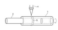
図1に示すとおり、JIS316Lステンレスパイプ(鉄)1(12Φ×1.0t×40L)にJIS3003のアルミ棒材2を圧入したサンプルを炭酸ガスレーザー溶接機4(松下溶接システム製YB-L150A8、ノズル径:5Φ、溶接速度:400mm/分、出力:700Wm、出力形態:CW)を用いてステンレスパイプ側(上方)からレーザーを照射、入熱して接合した。なお、図において5は溶接ビードを示す。そして、接合後、試作品2本を引張試験を行ったところ、いずれもアルミ側で母材破断し、優れた接合強度を有することを確認した。(Experimental example 1)
As shown in FIG. 1, a sample obtained by press-fitting a JIS 3003
そこで、本発明者らは、かかる優れた接合強度を有する接合体が溶接法により得られた理由を解明するために種々の調査、解析を行った。 Therefore, the present inventors conducted various investigations and analyzes in order to elucidate the reason why a joined body having such excellent joint strength was obtained by the welding method.
先ず、接合体の溶接部断面を顕微鏡(×10)にてマクロ観察を行った。図2は顕微鏡写真の模式図である。図1よりステンレスパイプ1の溶接をされた領域にはワイングラス状を呈したステンレス再凝固相A(以下、単に鉄再凝固相ということがある)が生成されており、その下部は砲弾状をなしてアルミ棒材2の中に没入した食込み部aとなっていることが分かる。そして、このステンレス鋼の食込み部aとアルミ棒材2の境界に両者の接合部Cが形成されている。Bはアルミ再凝固相を示している。 First, the cross section of the welded portion of the joined body was macro-observed with a microscope (× 10). FIG. 2 is a schematic diagram of a photomicrograph. As shown in FIG. 1, a stainless steel re-solidification phase A (hereinafter sometimes simply referred to as an iron re-solidification phase) having a wine glass shape is generated in the welded region of the
さらに、この接合体断面を顕微鏡(×100)によりミクロ観察を行った顕微鏡写真の模式図が図3である。図3から接合部Cはその両側の鉄再凝固相Aとアルミ再凝固相Bに複雑に絡み合った独立した境界相となっていることが知れる。Furthermore, FIG. 3 is a schematic diagram of a micrograph obtained by microscopically observing the bonded body cross section with a microscope (× 100). It can be seen fromFIG. 3 that the joint C is an independent boundary phase intricately intertwined with the iron resolidification phase A and the aluminum resolidification phase B on both sides.
次に、鉄再凝固相A、アルミ再凝固相B及びこの接合部(接合境界相)Cを電子線マイクロアナライザー(島津製EPMA−1400)で面分析と線分析を行った。図4は面分析観察の結果で、黒色が100%鉄、白色が100%アルミで、この間の組成を濃淡で示したものであり、同図下欄の数値はAl%でこれに相当する部分を引き出し腺で示した。これより、接合境界相はアルミを10〜50原子%含んでいることが判明した。また、図5は鋼再凝固相からアルミ再凝固相(アルミの地)の部位まで線分析により図3の矢印Xに沿って測定した結果である。図5より前記食込み部a(図2)を形成している鉄再凝固相Aはアルミを4原子%以上含み、接合部Cではアルミ再凝固相側に向かって鉄(Fe)が減少すると共にアルミ(Al)が増加し、鉄対アルミが等量からなる点を経て、アルミ量が急上昇してアルミ100原子%のアルミ再凝固相に至ることが分る。ニッケル(Ni)も鉄(Fe)と同様な変化を示している。Next, surface analysis and line analysis were performed on theiron resolidification phase A, the aluminum resolidification phase B, and the joint (bonding boundary phase) C with an electron beam microanalyzer (EPMA-1400 manufactured by Shimadzu). Figure 4 is the result of surface analysis viewing, black 100% iron, white 100% aluminum, and shows the meantime composition by shading, figures FIG lower columnyou equivalent thereto with Al% The part was shown with a pullout gland. From this, it was found that the joining boundary phase contains 10 to 50 atomic% of aluminum. FIG. 5 shows the results of measurement along the arrow X in FIG. 3 by line analysis from the steel resolidification phase to the aluminum resolidification phase (aluminum ground). From FIG. 5, the iron resolidification phase A forming the encroaching part a (FIG. 2) contains 4 atomic% or more of aluminum, and at the joint C, iron (Fe) decreases toward the aluminum resolidification phase side. It can be seen that aluminum (Al) increases, and the amount of aluminum rapidly rises to the aluminum resolidification phase of 100 atomic% of aluminum through the point where the amount of iron to aluminum is equal. Nickel (Ni) shows the same change as iron (Fe).
また、この接合部をオージェ電子分光分析(AES)により、鉄再凝固相側、中間部及びアルミ再凝固相側の3箇所について組成分析を行った。表1がその結果を示すものである。 Further, this joint was subjected to composition analysis at three locations on the iron resolidification phase side, the intermediate portion, and the aluminum resolidification phase side by Auger electron spectroscopy (AES). Table 1 shows the results.

表1の結果から接合部Cでは20〜29原子%のAlが存在していることが知れる。 From the results in Table 1, it is known that 20 to 29 atomic% Al is present in the joint C.
また、同接合部CをSEM分析で組織観察した結果、数ミクロンから十数ミクロンの大きさの急冷凝固組織が認められた。 Further, as a result of observing the structure of the joint C by SEM analysis, a rapidly solidified structure having a size of several to tens of microns was observed.
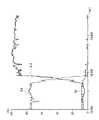
発明者らは、次にこの接合部Cに問題の金属間化合物が存在するかどうかを調査することにした。図6はX腺回折装置(理学電機製 RINT1500)を用いて接合部断面研磨面で測定を行ったX回折図形である。図6から、検出されたピークはAl、Fe及びFe−Cr−Niに相当するものでFe−Alの化合物に相当するピークは一切検出されなかったThe inventors next decided to investigate whether or not the intermetallic compound in question exists in the joint C. FIG. 6 is an X diffraction pattern measured on the polished surface of the joint section using an X-ray diffraction apparatus (RINT 1500 manufactured by Rigaku Corporation). From FIG.6 , the detected peaks correspond to Al, Fe, and Fe—Cr—Ni, and no peaks corresponding to the Fe—Al compound were detected.
これらの結果から、接合部の組織は鉄に対するアルミの固溶限(0.15%)を大幅に超えた状態になっており、しかもFe−Al金属間化合物が検出できなかったことから、結局Fe−Alの過飽和固溶体相として存在しているとの確信を得た。 From these results, the structure of the joint was in a state that greatly exceeded the solid solubility limit of aluminum (0.15%) with respect to iron, and Fe-Al intermetallic compounds could not be detected. The conviction that it exists as a supersaturated solid solution phase of Fe-Al was obtained.
また、この接合部に隣接している鉄再凝固相の砲弾状の食込み部aについてもAlがその固溶限を超える4%以上含有されていることから、やはりFe−Alの過飽和固溶体相であることが知れる。この食込み部aにおける過飽和に固溶したAlは、レーザー溶接時に高温となって発生したアルミ蒸気が溶融鉄内に分散して凝固したためである。 Further, since the shell-like encroached part a of the iron resolidification phase adjacent to this joint part contains 4% or more exceeding its solid solubility limit, it is still a supersaturated solid solution phase of Fe-Al. I know that there is. This is because the Al dissolved in the supersaturation in the encroaching portion a is solidified by being dispersed in the molten iron by the aluminum vapor generated at a high temperature during laser welding.
そして、上記接合部における過飽和固溶体相は前述の如く急冷凝固によって得られたものであり、特にレーザー溶接が溶接法のなかで接合部が最も急冷される方式であること、鉄とアルミの融点差が1000℃以上あること、さらにアルミの熱伝導特性が極めて高いことなどにより、急冷凝固が容易に実現されたものといえる。ここで言う、急冷凝固に必要な冷却速度は10K/s以上であれば足り、好ましくは100K/s以上である。これによって、数μ〜10μ以下の微細な凝固組織が得られる。 The supersaturated solid solution phase in the joint is obtained by rapid solidification as described above. In particular, laser welding is the method in which the joint is most rapidly cooled among the welding methods, and the melting point difference between iron and aluminum. It can be said that the rapid solidification is easily realized by the fact that the temperature is 1000 ° C. or higher and the thermal conductivity of aluminum is extremely high. Here, the cooling rate required for rapid solidification is 10 K / s or more, preferably 100 K / s or more. Thereby, a fine solidified structure of several μ to 10 μm or less is obtained.
次に本発明接合体の好ましい溶接条件などについて述べる。 Next, preferred welding conditions for the joined body of the present invention will be described.
十分な接合強度が得られるレーザー溶接条件は基本的には高エネルギー密度で鉄側から安定的に入熱し、溶解した鉄を短時間にアルミに適量砲弾状に食い込ませることを可能にすることである。この条件を満たすために、図7に示すように、まず、鉄(1)側からレーザー光(R)を照射して入熱を行い、溶融鉄(M)の内側に生成されたキーホール(K)内に金属蒸気(V)が封じ込められない様にし、この蒸気(V)による突沸を防ぐことが必要になる。また溶融鉄(M)が飛び散らないよう入熱を調整する必要がある。溶融鉄(M)がアルミ(2)に差し込むことにより凝固後鉄側表面に引けによる凹みが発生し易い。凝固表面の過度な凹み発生を防ぐためには、入熱は溶接深さ方向だけでなく、凝固時に入熱周辺から溶融鉄(M)量を補充するため、幅方向にも行う必要がある。この幅方向の入熱はキーホール(K)生成に伴って得られる金属蒸気(V)を鉄表面上すなわちキーホール(K)の上方近傍でプラズマ発光させて、ここに発生したプラズマ雲(P)継続的に維持させることが重要となる。 The laser welding conditions that can provide sufficient bonding strength are basically to stably input heat from the iron side at a high energy density, and to allow the molten iron to bite into the aluminum in an appropriate amount in a short time. is there. In order to satisfy this condition, as shown in FIG. 7, first, a laser beam (R) is irradiated from the iron (1) side to perform heat input, and a keyhole (inside the molten iron (M)) ( It is necessary to prevent the metal vapor (V) from being contained in K) and to prevent bumping by the vapor (V). Moreover, it is necessary to adjust heat input so that molten iron (M) does not scatter. When the molten iron (M) is inserted into the aluminum (2), a dent due to shrinkage tends to occur on the iron side surface after solidification. In order to prevent the occurrence of excessive dents on the solidified surface, the heat input needs to be performed not only in the welding depth direction but also in the width direction in order to supplement the amount of molten iron (M) from around the heat input during solidification. The heat input in the width direction causes the metal vapor (V) obtained with the generation of the keyhole (K) to emit plasma on the iron surface, that is, near the upper side of the keyhole (K), and a plasma cloud (P ) It is important to maintain it continuously.
このような状況を達成するための具体的な条件としては、レーザー出力は650〜850W(特に700〜750W)とし、溶接速度は375〜400mm/分とすることが好ましい。 As specific conditions for achieving such a situation, the laser output is preferably 650 to 850 W (particularly 700 to 750 W), and the welding speed is preferably 375 to 400 mm / min.
以下に、実施例として複数の実験例を挙げて本発明の効果を明確にする。
(実施例)
SUS304規格パイプとアルミ棒材、パイプをそれぞれ圧入した状態で、レーザー溶接機(松下溶接システム製YB−L150A8;アルゴンシール、ノズル径5φ)により溶接条件を変化させて接合試験を行った。その結果を表2に示す。No1〜No3は本発明の実施例(No1は前述の実験例と同じ)、No4〜No8は比較例である。SUSパイプは、No1〜5は12φ×1.0t×45L、No6〜7は12φ×1.0t×45Lの寸法のものを用いた。またアルミは、No1〜2は10φ×60L、No3〜5及びNo8は10φ×1.4t×60L,No6は14φ×40L、No7は17.3φ×2.0t×40Lの寸法のものを用いた。Hereinafter, a plurality of experimental examples will be given as examples to clarify the effects of the present invention.
(Example)
A SUS304 standard pipe, an aluminum bar, and a pipe were press-fitted, and a joining test was performed by changing welding conditions with a laser welding machine (YB-L150A8 manufactured by Matsushita Welding Systems; argon seal, nozzle diameter 5φ). The results are shown in Table 2. No1 to No3 are examples of the present invention (No1 is the same as the above experimental example), and No4 to No8 are comparative examples. As the SUS pipes, No. 1 to No. 5 of 12φ × 1.0t × 45L and No. 6 to 7 of 12φ × 1.0t × 45L were used. In addition, aluminum having a size of 10φ × 60L, No3 to 5 and No8 is 10φ × 1.4t × 60L, No6 is 14φ × 40L, and No7 is 17.3φ × 2.0t × 40L. .
表2から明かなように、本発明の実施例によれば何れも比較例に比べて著しく高い接合強度を有する鉄(SUS)とアルミの接合体が得られており、本発明の優れた効果を実証するものである。 As can be seen from Table 2, according to the examples of the present invention, a bonded body of iron (SUS) and aluminum having a significantly higher bonding strength than the comparative examples is obtained, and the excellent effects of the present invention are obtained. It is to prove.
1:ステンレスパイプ 2:アルミ棒
A:鉄(ステンレス鋼)再凝固相 B:アルミ再凝固相 C:接合部
a:食込み部 4:レーザー溶接機 5:溶接ビード
R:レーザー光 M:溶融鉄 K:キーホール V:金属蒸気
P:プラズマ雲
1: Stainless steel pipe 2: Aluminum rod A: Iron (stainless steel) resolidification phase B: Aluminum resolidification phase C: Joining part a: Biting part 4: Laser welding machine 5: Welding bead R: Laser beam M: Molten iron K : Keyhole V: Metallic vapor P: Plasma cloud
Claims (1)
Translated fromJapanesePriority Applications (1)
| Application Number | Priority Date | Filing Date | Title |
|---|---|---|---|
| JP2004213426AJP4178134B2 (en) | 2004-07-21 | 2004-07-21 | Method of joining an iron-based alloy member and an aluminum-based alloy member |
Applications Claiming Priority (1)
| Application Number | Priority Date | Filing Date | Title |
|---|---|---|---|
| JP2004213426AJP4178134B2 (en) | 2004-07-21 | 2004-07-21 | Method of joining an iron-based alloy member and an aluminum-based alloy member |
Publications (2)
| Publication Number | Publication Date |
|---|---|
| JP2006026724A JP2006026724A (en) | 2006-02-02 |
| JP4178134B2true JP4178134B2 (en) | 2008-11-12 |
Family
ID=35893674
Family Applications (1)
| Application Number | Title | Priority Date | Filing Date |
|---|---|---|---|
| JP2004213426AExpired - Fee RelatedJP4178134B2 (en) | 2004-07-21 | 2004-07-21 | Method of joining an iron-based alloy member and an aluminum-based alloy member |
Country Status (1)
| Country | Link |
|---|---|
| JP (1) | JP4178134B2 (en) |
Families Citing this family (8)
| Publication number | Priority date | Publication date | Assignee | Title |
|---|---|---|---|---|
| JP2006320953A (en)* | 2005-05-20 | 2006-11-30 | Nichirin Co Ltd | Body joined by welding dissimilar metal members made of ferrous alloy and aluminum alloy |
| US9683682B2 (en)* | 2012-08-03 | 2017-06-20 | Lincoln Global, Inc. | Methods and systems of joining pipes |
| US10464168B2 (en) | 2014-01-24 | 2019-11-05 | Lincoln Global, Inc. | Method and system for additive manufacturing using high energy source and hot-wire |
| CN106271069A (en)* | 2016-08-31 | 2017-01-04 | 武汉华工激光工程有限责任公司 | A kind of rustless steel and the method for laser welding of aluminium alloy |
| CN106735894B (en)* | 2016-12-13 | 2018-12-28 | 大族激光科技产业集团股份有限公司 | A kind of dissimilar metal micro-bonding method |
| US11027362B2 (en) | 2017-12-19 | 2021-06-08 | Lincoln Global, Inc. | Systems and methods providing location feedback for additive manufacturing |
| CN109079324A (en)* | 2018-09-30 | 2018-12-25 | 大族激光科技产业集团股份有限公司 | The method for laser welding of copper-nickel alloy |
| JP7211906B2 (en) | 2019-06-28 | 2023-01-24 | 株式会社神戸製鋼所 | Device for joining tubular members, method for joining dissimilar materials using same, and method for manufacturing tubular member with auxiliary member for joining dissimilar materials |
- 2004
- 2004-07-21JPJP2004213426Apatent/JP4178134B2/ennot_activeExpired - Fee Related
Also Published As
| Publication number | Publication date |
|---|---|
| JP2006026724A (en) | 2006-02-02 |
Similar Documents
| Publication | Publication Date | Title |
|---|---|---|
| US7156282B1 (en) | Titanium-aluminide turbine wheel and shaft assembly, and method for making same | |
| Ren et al. | Interface microstructure and mechanical properties of arc spot welding Mg–steel dissimilar joint with Cu interlayer | |
| Xu et al. | Tungsten inert gas welding–brazing of AZ31B magnesium alloy to TC4 titanium alloy | |
| Zhang et al. | Nd/YAG pulsed laser welding of TC4 titanium alloy to 301L stainless steel via pure copper interlayer | |
| Liu et al. | Joining of advanced high-strength steel to AA 6061 alloy by using Fe/Al structural transition joint | |
| Zhang et al. | Interfacial phenomena of cold metal transfer (CMT) welding of zinc coated steel and wrought aluminium | |
| Zhu et al. | Effect of laser-arc offset and laser-deviation angle on the control of a Ti-Al interlayer | |
| Giri et al. | Joining of titanium and stainless steel by using different welding processes: A review | |
| Sahul et al. | Disk laser weld brazing of AW5083 aluminum alloy with titanium grade 2 | |
| Du et al. | Investigation of porosity reduction, microstructure and mechanical properties for joining of selective laser melting fabricated aluminium composite via friction stir welding | |
| Nandan et al. | MIG and CMT brazing of aluminum alloys and steel: A review | |
| Song et al. | Effect of laser-GTAW hybrid welding heat input on the performance of Mg/Steel butt joint | |
| JP4178134B2 (en) | Method of joining an iron-based alloy member and an aluminum-based alloy member | |
| Kotadia et al. | Challenges and opportunities in remote laser welding of steel to aluminium | |
| Derbiszewski et al. | Studies on the quality of joints and phenomena therein for welded automotive components made of aluminum alloy—A review | |
| Dwivedi | Fundamentals of metal joining | |
| Biswas et al. | Applications of laser beam welding in automotive sector-a review | |
| Kurabayashi et al. | Dissimilar joining of immiscible Fe–Mg using solid metal dealloying | |
| Chen et al. | Achieving high strength joint of pure copper via laser-cold metal transfer arc hybrid welding | |
| Chu et al. | Structure-property correlation in weld metals and interface regions of titanium/steel dissimilar joints | |
| JP2021167013A (en) | Welded joint, its manufacturing method, and filler metal | |
| Raja et al. | Formation and influencing mechanism of the intermetallic compound in the friction stir welding of immiscible AZ31 and SPHC steel using aluminium powder as an additive | |
| Fan et al. | Influence of shoulder diameter on interfacial microstructure and mechanical behavior in dieless friction stir riveting of CP-Copper to 321 stainless steel | |
| Bang et al. | Effects of process parameters on friction stir weldability in dissimilar joints of AA5052 and advanced high strength steel | |
| Woohyun et al. | Brazability of Aluminum Alloy to Steels using Aluminum Filler Metal- Dissimilar Laser Brazing of Aluminum Alloy and Steels(Report 1)- |
Legal Events
| Date | Code | Title | Description |
|---|---|---|---|
| A977 | Report on retrieval | Free format text:JAPANESE INTERMEDIATE CODE: A971007 Effective date:20070419 | |
| A131 | Notification of reasons for refusal | Free format text:JAPANESE INTERMEDIATE CODE: A131 Effective date:20070424 | |
| A521 | Written amendment | Free format text:JAPANESE INTERMEDIATE CODE: A523 Effective date:20070620 | |
| A131 | Notification of reasons for refusal | Free format text:JAPANESE INTERMEDIATE CODE: A131 Effective date:20080422 | |
| A521 | Written amendment | Free format text:JAPANESE INTERMEDIATE CODE: A523 Effective date:20080425 | |
| A131 | Notification of reasons for refusal | Free format text:JAPANESE INTERMEDIATE CODE: A131 Effective date:20080603 | |
| A521 | Written amendment | Free format text:JAPANESE INTERMEDIATE CODE: A523 Effective date:20080605 | |
| TRDD | Decision of grant or rejection written | ||
| A01 | Written decision to grant a patent or to grant a registration (utility model) | Free format text:JAPANESE INTERMEDIATE CODE: A01 Effective date:20080819 | |
| A01 | Written decision to grant a patent or to grant a registration (utility model) | Free format text:JAPANESE INTERMEDIATE CODE: A01 | |
| A61 | First payment of annual fees (during grant procedure) | Free format text:JAPANESE INTERMEDIATE CODE: A61 Effective date:20080825 | |
| FPAY | Renewal fee payment (event date is renewal date of database) | Free format text:PAYMENT UNTIL: 20170829 Year of fee payment:9 | |
| R150 | Certificate of patent or registration of utility model | Free format text:JAPANESE INTERMEDIATE CODE: R150 | |
| FPAY | Renewal fee payment (event date is renewal date of database) | Free format text:PAYMENT UNTIL: 20170829 Year of fee payment:9 | |
| LAPS | Cancellation because of no payment of annual fees |