JP4177281B2 - Measuring apparatus and measuring method - Google Patents
Measuring apparatus and measuring methodDownload PDFInfo
- Publication number
- JP4177281B2 JP4177281B2JP2004096325AJP2004096325AJP4177281B2JP 4177281 B2JP4177281 B2JP 4177281B2JP 2004096325 AJP2004096325 AJP 2004096325AJP 2004096325 AJP2004096325 AJP 2004096325AJP 4177281 B2JP4177281 B2JP 4177281B2
- Authority
- JP
- Japan
- Prior art keywords
- shear wave
- vibrator
- test body
- time
- measuring
- Prior art date
- Legal status (The legal status is an assumption and is not a legal conclusion. Google has not performed a legal analysis and makes no representation as to the accuracy of the status listed.)
- Expired - Fee Related
Links
- 238000000034methodMethods0.000titledescription21
- 238000005259measurementMethods0.000claimsdescription18
- 239000002689soilSubstances0.000claimsdescription16
- 238000000691measurement methodMethods0.000claimsdescription12
- XLYOFNOQVPJJNP-UHFFFAOYSA-NwaterSubstancesOXLYOFNOQVPJJNP-UHFFFAOYSA-N0.000claimsdescription11
- 239000007769metal materialSubstances0.000claimsdescription5
- 230000000644propagated effectEffects0.000claimsdescription5
- RYGMFSIKBFXOCR-UHFFFAOYSA-NCopperChemical compound[Cu]RYGMFSIKBFXOCR-UHFFFAOYSA-N0.000claimsdescription3
- 229910000881Cu alloyInorganic materials0.000claimsdescription3
- 229910052802copperInorganic materials0.000claimsdescription3
- 239000010949copperSubstances0.000claimsdescription3
- 239000002184metalSubstances0.000claimsdescription3
- 229910052751metalInorganic materials0.000claimsdescription3
- 238000010008shearingMethods0.000claims1
- 230000001133accelerationEffects0.000description4
- 239000000919ceramicSubstances0.000description4
- 239000007788liquidSubstances0.000description4
- 238000010586diagramMethods0.000description2
- 230000003321amplificationEffects0.000description1
- 238000001514detection methodMethods0.000description1
- 238000002474experimental methodMethods0.000description1
- 238000003199nucleic acid amplification methodMethods0.000description1
- 230000010355oscillationEffects0.000description1
- 239000011148porous materialSubstances0.000description1
- 239000007787solidSubstances0.000description1
Images

Landscapes
- Investigating Or Analyzing Materials By The Use Of Ultrasonic Waves (AREA)
- Investigating Strength Of Materials By Application Of Mechanical Stress (AREA)
- Measurement Of Mechanical Vibrations Or Ultrasonic Waves (AREA)
- Geophysics And Detection Of Objects (AREA)
- Investigation Of Foundation Soil And Reinforcement Of Foundation Soil By Compacting Or Drainage (AREA)
Description
Translated fromJapanese本発明は、土壌の液状化後の排水過程におけるせん断波速度を測定するための測定装置及び測定方法に関する。 The present invention relates to a measuring apparatus and a measuring method for measuring a shear wave velocity in a drainage process after soil liquefaction.
地盤の液状化による被害を精度良く予測するためには、液状化後の排水過程(間隙水圧消散過程)におけるせん断剛性を求める必要がある。せん断剛性は、せん断波の速度を測定することにより、関係式から算出できる。具体的には、せん断剛性をGs、せん断波速度をVs、測定対象となる地盤の密度をρとすると、せん断剛性Gsは、下記式(1)から求められる。 In order to accurately predict damage due to liquefaction of the ground, it is necessary to determine the shear stiffness in the drainage process (pore water pressure dissipation process) after liquefaction. The shear stiffness can be calculated from the relational expression by measuring the shear wave velocity. Specifically, when the shear stiffness is Gs, the shear wave velocity is Vs, and the density of the ground to be measured is ρ, the shear stiffness Gs is obtained from the following equation (1).
Gs=ρ×Vs・・・(1) Gs = ρ × Vs (1)
このため、従来から、室内での模型実験によってせん断波速度の測定が行われている。せん断波速度の測定方法としては、例えば、上部と底部とに圧電セラミック振動子が取り付けられた容器を用いた測定方法が知られている(例えば、特許文献1参照。)。 For this reason, conventionally, the shear wave velocity has been measured by an indoor model experiment. As a method for measuring the shear wave velocity, for example, a measurement method using a container in which a piezoelectric ceramic vibrator is attached to an upper part and a bottom part is known (see, for example, Patent Document 1).
上記の測定方法では、以下の手順で、液状化後の排水過程におけるせん断波の速度が測定される。先ず、容器内に試験体となる土壌のサンプルを充填し、試験体に上方から荷重をかけて、土壌サンプルの液状化を行う。これにより、水と土とが分離し、試験体の上面に水が浮き出た状態となる。 In the above measuring method, the shear wave velocity in the drainage process after liquefaction is measured by the following procedure. First, a soil sample to be a test body is filled in a container, and a load is applied to the test body from above to liquefy the soil sample. Thereby, water and soil will separate and it will be in the state where water floated on the upper surface of the test body.
次に、上部の圧電セラミック振動子にパルス信号を入力して、せん断波(S波)を発生させる。次いで、底部の圧電セラミック振動子によってせん断波を受信して、せん断波の到達時間を測定する。さらに、測定された到達時間からせん断波速度を算出する。このように、上記の測定方法によれば、簡単にせん断波速度を求めることができる。
しかしながら、上記の測定方法においては、圧電セラミック振動子は、試験体の上下に配置されている。また、せん断波は、媒質の形の変化によって伝わるS波(横波)であるため、固体は伝播するが、液体は伝播しないという性質を有している。このため、上記の測定方法においては、液状化によって試験体の上面に水が浮き出た状態になると、せん断波の伝播経路に液体が介在することとなり、正確なせん断波速度の測定は困難となる。 However, in the measurement method described above, the piezoelectric ceramic vibrators are arranged above and below the specimen. Further, since the shear wave is an S wave (transverse wave) transmitted by a change in the shape of the medium, the solid wave propagates but the liquid does not propagate. For this reason, in the measurement method described above, when water is brought out on the upper surface of the specimen due to liquefaction, the liquid is interposed in the propagation path of the shear wave, and it is difficult to accurately measure the shear wave velocity. .
本発明の目的は、上記問題を解消し、液状化によって水と土とが分離した状態においても正確にせん断波速度を測定し得る測定装置及び測定方法を提供することにある。 An object of the present invention is to provide a measuring apparatus and a measuring method capable of solving the above-described problems and accurately measuring the shear wave velocity even in a state where water and soil are separated by liquefaction.
上記目的を達成するために本発明における測定装置は、試験体を伝わるせん断波の速度を測定するための測定装置であって、前記試験体となる土壌サンプルを収納する容器と、一方の端部が閉塞された筒体と、前記筒体の内面に衝突して、前記試験体の内部でせん断波を発生させる剛体と、測定部と、第1の振動子と、第2の振動子と、前記第2の振動子を前記試験体中の予め定められた位置で保持するための保持部材とを少なくとも有し、前記筒体は、前記一方の端部が前記試験体中に埋設されるように配置されるものであり、前記保持部材は、前記筒体から離れた位置に全部又は一部が前記試験体中に埋設されるように配置されるものであり、前記第1の振動子は、前記筒体に取り付けられ、前記筒体で発生した前記せん断波を検知して前記測定部へ通知し、前記第2の振動子は、前記第2の振動子まで伝播した前記せん断波を検知して前記測定部へ通知し、前記測定部は、第1の振動子が前記せん断波を検知した時点と第2の振動子が前記せん断波を検知した時点との間の時間を測定し、測定した前記時間に基づいて前記せん断波の速度を算出することを特徴とする。 In order to achieve the above object, a measuring apparatus according to the present invention is a measuring apparatus for measuring the velocity of a shear wave that travels through a specimen, and a container that houses a soil sample serving as the specimen, and one end of the container. A closed cylinder, a rigid body that collides with the inner surface of the cylinder and generates a shear wave inside the test body, a measurement unit, a first vibrator, a second vibrator, A holding member for holding the second vibrator at a predetermined position in the test body, and the cylindrical body is configured such that the one end is embedded in the test body. The holding member is arranged so that all or part of the holding member is embedded in the test body at a position away from the cylindrical body, and the first vibrator is , Attached to the cylinder and detecting the shear wave generated in the cylinder The measurement unit is notified, the second transducer detects the shear wave propagated to the second transducer and notifies the measurement unit, and the measurement unit is configured such that the first transducer is the first transducer. A time between the time when the shear wave is detected and the time when the second vibrator detects the shear wave is measured, and the velocity of the shear wave is calculated based on the measured time.
また、上記目的を達成するため本発明における測定方法は、試験体を伝わるせん断波の速度を測定するための測定方法であって、(a)一方の端部が閉塞された筒体を、前記試験体となる土壌サンプルに、閉塞された前記一方の端部が前記試験体中に埋設されるようにして配置した状態で、前記筒体の内面に剛体を衝突させて、せん断波を発生させる工程と、(b)前記剛体の衝突によってせん断波が発生した時点と、前記せん断波が前記試験体中の予め定められた位置に到達した時点との間の時間を測定する工程と、(c)前記(b)の工程で測定された前記時間に基づいて、前記せん断波の速度を算出する工程とを少なくとも有することを特徴とする。 Further, in order to achieve the above object, the measuring method in the present invention is a measuring method for measuring the velocity of the shear wave transmitted through the test body, and (a) the cylinder whose one end is closed, A shear wave is generated by colliding a rigid body against the inner surface of the cylindrical body in a state in which the one end that has been blocked is embedded in the specimen, in a soil sample to be a test body. And (b) measuring a time between a point in time when a shear wave is generated by the collision of the rigid body and a point in time when the shear wave reaches a predetermined position in the specimen, and (c) And (b) calculating the shear wave velocity based on the time measured in the step (b).
以上のように本発明における測定装置及び測定方法によれば、試験体である土壌サンプルの内部においてせん断波の発生が行われる。また、せん断波が発生した時点から、せん断波が試験体中の予め定められた位置に到達する時点までの時間(伝播時間)を測定し、測定した伝播時間を用いてせん断波速度を算出している。このため、土壌サンプルを液状化させて、水を浮き出させた状態であっても、せん断波の伝播経路に液体が介在しないため、正確なせん断波速度を測定できる。 As described above, according to the measuring apparatus and the measuring method of the present invention, shear waves are generated inside the soil sample as the test body. Also, measure the time (propagation time) from the time when the shear wave occurs to the time when the shear wave reaches a predetermined position in the specimen, and calculate the shear wave velocity using the measured propagation time. ing. For this reason, even when the soil sample is liquefied and the water is raised, the liquid does not intervene in the propagation path of the shear wave, so that the accurate shear wave velocity can be measured.
上記本発明における測定装置においては、前記筒体の他方の端部が開口し、前記筒体が、金属材料で形成され、前記他方の端部が前記試験体から露出し、且つ、前記一方の端部が前記容器の底面に接触しないように配置されており、前記剛体が、金属製の球体と、前記球体に取り付けられた棒体とで形成されている態様とするのが好ましい。このような態様とすれば、任意の時間間隔での連続したせん断波の発生が容易なものとなる。 In the measuring apparatus according to the present invention, the other end of the cylinder is open, the cylinder is formed of a metal material, the other end is exposed from the test body, and the one It is preferable that the end is arranged so as not to contact the bottom surface of the container, and the rigid body is formed of a metal sphere and a rod attached to the sphere. With such an embodiment, it becomes easy to generate continuous shear waves at arbitrary time intervals.
また、上記本発明における測定装置においては、前記保持部材が短冊状に形成されており、前記保持部材には、複数の前記第2の振動子が前記保持部材の長手方向に沿って配置されている態様とするのも好ましい。また、前記保持部材は銅又は銅合金で形成され、その厚みが0.2mm〜0.5mmの範囲に設定されているのが好ましい。このような態様とする場合は、せん断波の検知の正確性を向上できる。 Further, in the measuring apparatus according to the present invention, the holding member is formed in a strip shape, and the plurality of second vibrators are arranged along the longitudinal direction of the holding member on the holding member. It is also preferable to adopt an embodiment. The holding member is preferably made of copper or a copper alloy, and the thickness thereof is preferably set in the range of 0.2 mm to 0.5 mm. In the case of such an aspect, the accuracy of shear wave detection can be improved.
また、上記本発明における測定装置においては、前記測定部が、前記せん断波の速度に、前記試験体の密度を乗じて、前記試験体のせん断剛性を算出する態様とすることもできる。更に、前記試験体が液状化によって水と土とに分離した状態にあっても良い。 In the measurement apparatus according to the present invention, the measurement unit may calculate the shear rigidity of the test body by multiplying the shear wave velocity by the density of the test body. Furthermore, the test body may be separated into water and soil by liquefaction.
上記本発明における測定方法においては、前記(a)の工程を実行する前に、前記試験体の液状化をさせる工程を更に有し、その後、前記(a)の工程から前記(c)の工程までを複数回実行することにより、前記せん断波の速度の経時変化を測定する態様であっても良い。また、上記本発明における測定方法においては、前記せん断波の速度に、前記試験体の密度を乗じて、前記試験体のせん断剛性を算出する工程を更に有する態様であっても良い。 In the measurement method according to the present invention, the method further includes the step of liquefying the specimen before the step (a) is performed, and then the step (a) to the step (c). A mode in which the change with time of the speed of the shear wave is measured may be performed by executing the above multiple times. The measurement method according to the present invention may further include a step of calculating the shear rigidity of the test specimen by multiplying the velocity of the shear wave by the density of the test specimen.
以下、本発明における測定装置及び測定方法について図面を用いて説明する。最初に、本発明の測定装置の構成について図1を用いて説明する。図1は、本発明の測定装置の一例を示す断面構成図である。 Hereinafter, a measuring apparatus and a measuring method according to the present invention will be described with reference to the drawings. Initially, the structure of the measuring apparatus of this invention is demonstrated using FIG. FIG. 1 is a cross-sectional configuration diagram showing an example of the measuring apparatus of the present invention.
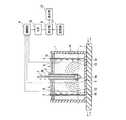
図1に示す測定装置は、試験体14を伝わるせん断波13の速度を測定するための装置である。試験体14は、土壌サンプルである。図1に示すように、測定装置は、試験体14を収納する容器1、一方の端部が閉塞された筒体2、剛体3、複数の保持部材4、第1の振動子5、複数の第2の振動子6、及びせん断波速度を算出する測定部8を少なくとも備えている。 The measuring apparatus shown in FIG. 1 is an apparatus for measuring the velocity of the
図1の例では、測定装置は、更に、増幅部9、A/D変換器10、記憶部11及び表示部12も備えている。また、図1の例では、容器1は、振動台7の上に載置されている。振動台7は、アクチュエータ(図示せず)により、横方向に(図1中の矢印の方向)振動できるように構成されている。振動台7によって容器1を振動することにより、図1に示すように試験体14の上に水15を浮き出させて、試験体14を液状化させることができる。 In the example of FIG. 1, the measurement apparatus further includes an amplification unit 9, an A /
また、図1に示すように、筒体2は、閉塞された一方の端部が試験体14中に埋設され、開口した他方の端部が試験体14から露出するように配置されている。剛体3は、筒体2の内部の底面に衝突できるように形成されている。 Further, as shown in FIG. 1, the cylindrical body 2 is arranged so that one closed end is embedded in the
図1の例では、剛体を自由落下させて、筒体2の底面に衝突させることによって、試験体14の内部でせん断波13を発生させている。落下後の剛体3の引き上げは、人手によって行われる。なお、落下後の剛体3を引き上げるための装置を取り付けることもできる。 In the example of FIG. 1, the
また、図1の例では、剛体3は、落下後の引き上げを容易にし、且つ、任意の時間間隔での連続的なせん断波の発生を容易にするため、球体3aに棒体3bを取り付けて形成されている。但し、本発明において、剛体3の形状は、筒体2の内面に衝突させることができる形状であれば良く、例えば、球体3a又は棒体3bのみで構成されたものであっても良い。更に、せん断波13の発生を容易にするため、筒体2及び剛体3は、共に金属材料で形成するのが好ましい。筒体2及び剛体3を形成する金属材料は特に限定されるものではない。なお、図1の例では、球体3aのみを金属材料で形成した態様とすることもできる。 Further, in the example of FIG. 1, the rigid body 3 has a
また、図1の例では、筒体2は、閉塞した端部が容器1の底面に接触しないように配置されている。これは、筒体2が容器1の底面に接触していると、発生したせん断波13が容器や振動台7を伝播してしまい、これらを伝播したせん断波の速度までもが測定されてしまう可能性があるからである。 In the example of FIG. 1, the cylindrical body 2 is arranged so that the closed end portion does not contact the bottom surface of the container 1. This is because when the cylindrical body 2 is in contact with the bottom surface of the container 1, the generated
保持部材4は、第2の振動子6を試験体14中の予め定められた位置で保持するために用いられ、筒体2から離れた位置に全部又は一部が試験体14中に埋設されるように配置される。本発明において、保持部材4は、第2の振動子6を保持できるものであれば良く、特に限定されるものではない。但し、振動台7による試験体14の液状化を妨げないようにするため、液状化の際に試験体14と一緒に動くように形成されているのが好ましい。 The holding member 4 is used to hold the second vibrator 6 at a predetermined position in the
このため、図1の例では、保持部材4は、短冊状の金属製の薄板で形成されている(図2参照)。また、適度な弾性を有し、厚みの制御が容易な点から、保持部材4は、銅又は銅合金の薄板で形成するのが特に好ましい。この場合、厚みは0.2mm〜0.5mmの範囲に設定するのが好ましい。 For this reason, in the example of FIG. 1, the holding member 4 is formed of a strip-shaped metal thin plate (see FIG. 2). In addition, the holding member 4 is particularly preferably formed of a thin plate of copper or a copper alloy from the viewpoint of appropriate elasticity and easy thickness control. In this case, the thickness is preferably set in the range of 0.2 mm to 0.5 mm.
また、保持部材4は、図1に示すように容器1の底面に固定するのが好ましい。保持部材4は、液状化の際に試験体14と一体となって動くため、固定していない場合は、試験体14の動きが停止した後に保持部材4の位置がずれ、せん断波13の速度の算出を正確に行えない可能性があるからである。 Further, the holding member 4 is preferably fixed to the bottom surface of the container 1 as shown in FIG. Since the holding member 4 moves integrally with the
第1の振動子5及び第2の振動子6は、共に、せん断波13を検知する。具体的には、第1の振動子5は筒体2に取り付けられており、剛体3の筒体2への衝突によって筒体で発生したせん断波13を検知する。一方、第2の振動子6は保持部材4に取り付けられており、第2の振動子6の位置まで伝播したせん断波13を検知する。このため、第1の振動子5によってせん断波13の発生時刻を知ることができ、第2の振動子6によってその取り付け位置にせん断波13が伝播した時刻を知ることができる。 Both the
第1の振動子5は、剛体3が筒体2の底面に衝突することによってせん断波13が発生するため、図1に示すように、筒体2の底面に最も近接した位置に取り付けるのが好ましい。また、せん断波13の速度の正確性を向上させるため、図1に示すように、複数の保持部材4を配置し、各保持部材4に複数の第2の振動子を取り付けるのが好ましい。この場合、複数の第2の振動子6は、保持部材4の長手方向に沿って等間隔で取り付けるのが好ましく、保持部材4は、その長手方向が筒体2の長手方向と一致し、且つその法線方向が筒体2の半径方向と一致するように配置するのが好ましい。なお、図1の例では、2枚の保持部材4が配置されている。 Since the
図1の例では、第1の振動子5及び第2の振動子6としては、圧電素子を備えた加速度センサが用いられている。第1の振動子5又は第2の振動子6にせん断波13が伝播すると、第1の振動子5又は第2の振動子6から、せん断波13を検知したことを通知する信号が測定部8へと出力される。また、図1の例では、第1の振動子5及び第2の振動子6が出力した信号は、先ず増幅部9によって増幅された後、A/D変換器10によってデジタル信号に変換され、その後、測定部8に入力される。 In the example of FIG. 1, an acceleration sensor provided with a piezoelectric element is used as the
なお、第1の振動子5及び第2の振動子6としては、圧電素子を備えた加速度センサ以外のものを用いることもできる。例えば、コイルと磁石とを備えたサーボ式加速度変換器や、ひずみゲージを備えたひずみゲージ式加速度変換器等を用いることもできる。 In addition, as the
測定部8は、第1の振動子5及び第2の振動子6からせん断波13を検知したことを示す信号を受信すると、第1の振動子5から信号が出力された時点(起振時刻)と第2の振動子6から信号が出力された時点(受振時刻)との間の時間(伝播時間)を測定する。この伝播時間は、せん断波13が発生してから保持部材4に到達するまでの時間に相当する。また、測定部8は、測定した伝播時間を用いてせん断波13の速度を算出する。 When the measurement unit 8 receives a signal indicating that the
図1の例では、各保持部材4には、複数の第2の振動子6が保持部材4の長手方向に沿って等間隔で取り付けられているため、第2の振動子6毎に伝播時間が測定される。また、記憶部11には、第2の振動子6毎に、筒体2からの距離が格納されている。このため、測定部8は、第2の振動子6毎に、記憶部11から距離を読み出し、読み出した距離を計測した時間で除してせん断波13の速度を算出する。算出されたせん断波13の速度は、表示部12に表示される。 In the example of FIG. 1, a plurality of second vibrators 6 are attached to each holding member 4 at equal intervals along the longitudinal direction of the holding member 4. Is measured. The
なお、図1の例では、各第2の振動子6において、筒体2までの距離は、筒体2の側面から保持部材4までの距離Lと、保持部材4上のポイント16までの距離とによって、三角法を用いて算出されている。また、図1の例では、筒体2の底面に剛体3が衝突することによってせん断波13が発生しており、筒体2の底面が起振点となっている。このため、図1に示すようにポイント16は、保持部材4上の筒体2の底面と同高さに位置する点に設定されている。 In the example of FIG. 1, in each second vibrator 6, the distance to the cylinder 2 is the distance L from the side surface of the cylinder 2 to the holding member 4 and the distance to the
また、図1に示す測定装置においては、測定部8によって、上述した式(1)を用いてせん断剛性を算出させることもできる。この場合、表示部12には、算出されたせん断剛性も表示される。 Further, in the measuring apparatus shown in FIG. 1, the shear stiffness can be calculated by the measurement unit 8 using the above-described equation (1). In this case, the calculated shear rigidity is also displayed on the
次に、本発明における測定方法について図2を用いて説明する。図2は、本発明における測定方法の一例を示すフロー図である。但し、以下の例では、図1に示す測定装置を用いて本発明における測定方法が実施される。また、剛体3の筒体2への衝突は自由落下によって行われている。更に、以下の例では、試験体14の液状化後の排水過程におけるせん断波速度の測定が行われている。 Next, the measurement method in the present invention will be described with reference to FIG. FIG. 2 is a flowchart showing an example of the measuring method in the present invention. However, in the following example, the measurement method according to the present invention is implemented using the measurement apparatus shown in FIG. Further, the collision of the rigid body 3 with the cylindrical body 2 is performed by free fall. Furthermore, in the following example, the shear wave velocity is measured in the drainage process after the
先ず、試験体14を液状化させるため、振動台7による容器1の振動を行って、試験体14の上面に水15を浮き立たせる(ステップS1)。次に、剛体3を自由落下させて、筒体2に衝突させ、せん断波13を発生させる(ステップS2)。 First, in order to liquefy the
次いで、測定部8によって、せん断波13が発生した時点と、せん断波13が試験体14中の予め定められた位置に到達した時点との間の時間、即ち、伝播時間を測定する(ステップS3)。なお、本例では、上述したように、せん断波13が発生した時点は、筒体2に取り付けられた第1の振動子5によって検知される。また、せん断波13が試験体14中の予め定められた位置に到達した時点は、試験体14中の保持部材4に取り付けられた第2の振動子6によって検知される。また、伝播時間の測定は、第2の振動子6毎に行われる。 Next, the time between the time when the
次に、測定部8によって、せん断波13の速度の算出が行われる(ステップS4)。なお、本例では、せん断波13の速度の算出も第2の振動子6毎に行われる。その後、算出されたせん断波13が表示部12に表示される(ステップS5)。 Next, the velocity of the
ステップS5の終了後、設定された時間が経過していない場合は、更にステップS2〜S5を実行する(ステップS6)。このステップS2〜S5を繰り返し行うことにより、せん断波速度の経時変化が測定されることとなる。設定された時間が経過している場合は、処理を終了する。 If the set time has not elapsed after step S5, steps S2 to S5 are further executed (step S6). By repeating these steps S2 to S5, the change with time in the shear wave velocity is measured. If the set time has elapsed, the process ends.
なお、本例では、ステップS4の実行後に更にせん断剛性を算出し、ステップS5においてせん断剛性も表示する態様とすることもできる。また、この態様によれば、せん断剛性の経時変化も測定できる。 In addition, in this example, it can also be set as the aspect which calculates shear rigidity further after execution of step S4 and displays shear rigidity in step S5. Further, according to this aspect, it is possible to measure a change in shear rigidity with time.
このように、本発明の測定装置及び測定方法によれば、試験体となる土壌サンプルが液状化している状態であっても、従来のようにせん断波の伝播経路に液体が介在しないため、正確なせん断波速度の測定が行える。 As described above, according to the measuring apparatus and the measuring method of the present invention, even when the soil sample serving as the test body is in a liquefied state, the liquid does not intervene in the propagation path of the shear wave as in the conventional case. Can measure the shear wave velocity.
以上のように、本発明の測定装置及び測定方法を用いることで、液状化後のせん断波速度の測定を正確に行うことができる。また、この結果、液状化後のせん断剛性を正確に求めることができるので、地盤の液状化による被害を精度良く予測することができる。 As described above, the shear wave velocity after liquefaction can be accurately measured by using the measuring apparatus and measuring method of the present invention. As a result, since the shear rigidity after liquefaction can be accurately obtained, damage due to liquefaction of the ground can be accurately predicted.
1 容器
2 筒体
3 剛体
3a 球体
3b 棒体
4 保持部材
5 第1の振動子
6 第2の振動子
7 振動台
8 測定部
9 増幅部
10 A/D変換器
11 記憶部
12 表示部
13 せん断波
14 試験体(土壌サンプル)
15 水
16 ポイントDESCRIPTION OF SYMBOLS 1 Container 2 Cylindrical body 3
15
Claims (9)
Translated fromJapanese前記試験体となる土壌サンプルを収納する容器と、一方の端部が閉塞された筒体と、前記筒体の内面に衝突して、前記試験体の内部でせん断波を発生させる剛体と、測定部と、第1の振動子と、第2の振動子と、前記第2の振動子を前記試験体中の予め定められた位置で保持するための保持部材とを少なくとも有し、
前記筒体は、前記一方の端部が前記試験体中に埋設されるように配置されるものであり、前記保持部材は、前記筒体から離れた位置に全部又は一部が前記試験体中に埋設されるように配置されるものであり、
前記第1の振動子は、前記筒体に取り付けられ、前記筒体で発生した前記せん断波を検知して前記測定部へ通知し、前記第2の振動子は、前記第2の振動子まで伝播した前記せん断波を検知して前記測定部へ通知し、
前記測定部は、第1の振動子が前記せん断波を検知した時点と第2の振動子が前記せん断波を検知した時点との間の時間を測定し、測定した前記時間に基づいて前記せん断波の速度を算出する測定装置。A measuring device for measuring the speed of a shear wave traveling through a specimen,
A container for storing a soil sample to be the test body, a cylindrical body with one end closed, a rigid body that collides with the inner surface of the cylindrical body and generates shear waves inside the test body, and measurement At least a first member, a first vibrator, a second vibrator, and a holding member for holding the second vibrator at a predetermined position in the test body,
The cylindrical body is arranged such that the one end is embedded in the test body, and the holding member is wholly or partially in a position away from the cylindrical body. It is arranged to be buried in the
The first vibrator is attached to the cylindrical body, detects the shear wave generated in the cylindrical body, and notifies the measurement unit, and the second vibrator extends to the second vibrator. Detecting the propagated shear wave and notifying the measurement unit,
The measuring unit measures a time between a time when the first vibrator detects the shear wave and a time when the second vibrator detects the shear wave, and the shearing unit is based on the measured time. A measuring device that calculates the velocity of waves.
前記剛体が、金属製の球体と、前記球体に取り付けられた棒体とで形成されている請求項1記載の測定装置。The other end of the cylinder is open, the cylinder is formed of a metal material, the other end is exposed from the test body, and the one end contacts the bottom surface of the container. Are arranged not to
The measuring apparatus according to claim 1, wherein the rigid body is formed of a metal sphere and a rod attached to the sphere.
(a)一方の端部が閉塞された筒体を、前記試験体となる土壌サンプルに、閉塞された前記一方の端部が前記試験体中に埋設されるようにして配置した状態で、前記筒体の内面に剛体を衝突させて、せん断波を発生させる工程と、
(b)前記剛体の衝突によってせん断波が発生した時点と、前記せん断波が前記試験体中の予め定められた位置に到達した時点との間の時間を測定する工程と、
(c)前記(b)の工程で測定された前記時間に基づいて、前記せん断波の速度を算出する工程とを少なくとも有する測定方法。A measurement method for measuring the velocity of a shear wave that travels through a specimen,
(A) In a state where the cylinder whose one end is closed is arranged in the soil sample to be the test body so that the one end closed is embedded in the test body, A step of causing a rigid body to collide with the inner surface of the cylindrical body to generate a shear wave;
(B) measuring a time between a time when the shear wave is generated by the collision of the rigid body and a time when the shear wave reaches a predetermined position in the test body;
(C) A measurement method including at least a step of calculating a velocity of the shear wave based on the time measured in the step (b).
Priority Applications (1)
| Application Number | Priority Date | Filing Date | Title |
|---|---|---|---|
| JP2004096325AJP4177281B2 (en) | 2004-03-29 | 2004-03-29 | Measuring apparatus and measuring method |
Applications Claiming Priority (1)
| Application Number | Priority Date | Filing Date | Title |
|---|---|---|---|
| JP2004096325AJP4177281B2 (en) | 2004-03-29 | 2004-03-29 | Measuring apparatus and measuring method |
Publications (2)
| Publication Number | Publication Date |
|---|---|
| JP2005283265A JP2005283265A (en) | 2005-10-13 |
| JP4177281B2true JP4177281B2 (en) | 2008-11-05 |
Family
ID=35181828
Family Applications (1)
| Application Number | Title | Priority Date | Filing Date |
|---|---|---|---|
| JP2004096325AExpired - Fee RelatedJP4177281B2 (en) | 2004-03-29 | 2004-03-29 | Measuring apparatus and measuring method |
Country Status (1)
| Country | Link |
|---|---|
| JP (1) | JP4177281B2 (en) |
Cited By (2)
| Publication number | Priority date | Publication date | Assignee | Title |
|---|---|---|---|---|
| CN103884319A (en)* | 2014-03-13 | 2014-06-25 | 内蒙古电力勘测设计院 | Total station-free tower footing cross-section diagram measuring method and equipment |
| CN110507360A (en)* | 2014-08-28 | 2019-11-29 | 深圳迈瑞生物医疗电子股份有限公司 | Shearing wave imaging method and system |
Families Citing this family (7)
| Publication number | Priority date | Publication date | Assignee | Title |
|---|---|---|---|---|
| KR101123791B1 (en)* | 2007-07-24 | 2012-03-13 | 고려대학교 산학협력단 | Apparatus for measuring soil disturbance in soil sampler by using shear wave and Method of measuring the same |
| JP5526290B1 (en)* | 2013-04-02 | 2014-06-18 | 報国エンジニアリング株式会社 | Sampling apparatus and method for liquefaction determination |
| CN105212968B (en)* | 2015-10-29 | 2019-01-04 | 无锡海斯凯尔医学技术有限公司 | Elastomeric check method and apparatus |
| CN106770656B (en)* | 2016-12-21 | 2023-02-21 | 西南交通大学 | Testing device for dynamic shear modulus of soil body in model test |
| CN112326408B (en)* | 2020-10-09 | 2023-04-21 | 南京理工大学 | System and method for measuring wave velocity of solid medium under confining pressure |
| CN112649287B (en)* | 2021-01-18 | 2024-07-12 | 大连理工大学 | External excitation test device, test system and method for measuring soil shear wave velocity in large triaxial test |
| CN116972954B (en)* | 2023-09-25 | 2023-12-19 | 山东省地震工程研究院 | Rock-soil wave velocity measurement method and device based on in-situ excitation |
- 2004
- 2004-03-29JPJP2004096325Apatent/JP4177281B2/ennot_activeExpired - Fee Related
Cited By (4)
| Publication number | Priority date | Publication date | Assignee | Title |
|---|---|---|---|---|
| CN103884319A (en)* | 2014-03-13 | 2014-06-25 | 内蒙古电力勘测设计院 | Total station-free tower footing cross-section diagram measuring method and equipment |
| CN103884319B (en)* | 2014-03-13 | 2016-10-12 | 内蒙古电力勘测设计院有限责任公司 | Exempt from tower base sectional drawing measuring method and the equipment of total powerstation |
| CN110507360A (en)* | 2014-08-28 | 2019-11-29 | 深圳迈瑞生物医疗电子股份有限公司 | Shearing wave imaging method and system |
| CN110507360B (en)* | 2014-08-28 | 2022-06-03 | 深圳迈瑞生物医疗电子股份有限公司 | Shear wave imaging method and system |
Also Published As
| Publication number | Publication date |
|---|---|
| JP2005283265A (en) | 2005-10-13 |
Similar Documents
| Publication | Publication Date | Title |
|---|---|---|
| US7623974B2 (en) | System and method for detecting onset of structural failure | |
| JP4177281B2 (en) | Measuring apparatus and measuring method | |
| JP5466950B2 (en) | Ultrasonic surface monitoring method | |
| JP2008224632A (en) | Method of measuring impact absorption energy using drop weight impact tester and drop weight impact tester | |
| Espíndola et al. | Ultrasound induces aging in granular materials | |
| JP5163857B2 (en) | Concrete structure quality inspection method and concrete structure quality inspection apparatus | |
| CN106769560B (en) | A vibration-based nondestructive testing method for mechanical parameters of I-beams | |
| WO2019093294A1 (en) | Estimating device, estimating method, and program storing medium | |
| JP5830315B2 (en) | Container vibration test method and test apparatus | |
| JP2007303947A (en) | Ice thickness measuring method and device therefor | |
| KR100997810B1 (en) | Damage Detection Method of Structure Using Vibration Power | |
| JP7060533B2 (en) | Shear wave velocity measuring device | |
| KR101931686B1 (en) | System for monitoring wall-thinning of pipe and method thereof | |
| JP5378093B2 (en) | Rail axial force measuring device and rail axial force measuring method | |
| CN102410871B (en) | Indoor measuring device for shearing wave velocity of soil body | |
| US6756548B2 (en) | Apparatus and method for measuring mass in a microgravity environment | |
| JP2012036590A (en) | Drilling hole measuring apparatus and program | |
| KR20150009546A (en) | Method for measuring the fill level of a fluid | |
| CN102680075A (en) | Device and method for testing vibration isolation performance of corrugated pipe under free work condition | |
| US20090271130A1 (en) | Method for measuring suspended sediment concentration in water | |
| EP2895825B1 (en) | Acoustic flexural order level sensor | |
| Rew et al. | Design of automatic tension control device for a vibrating wire sensor | |
| CN202547769U (en) | Apparatus for testing bellows vibration isolation performance under free condition | |
| JP3843108B2 (en) | Specimen reaction force estimation device | |
| JP7489638B2 (en) | Non-destructive testing equipment |
Legal Events
| Date | Code | Title | Description |
|---|---|---|---|
| A621 | Written request for application examination | Free format text:JAPANESE INTERMEDIATE CODE: A621 Effective date:20060428 | |
| A977 | Report on retrieval | Free format text:JAPANESE INTERMEDIATE CODE: A971007 Effective date:20080715 | |
| TRDD | Decision of grant or rejection written | ||
| A01 | Written decision to grant a patent or to grant a registration (utility model) | Free format text:JAPANESE INTERMEDIATE CODE: A01 Effective date:20080814 | |
| A01 | Written decision to grant a patent or to grant a registration (utility model) | Free format text:JAPANESE INTERMEDIATE CODE: A01 | |
| A61 | First payment of annual fees (during grant procedure) | Free format text:JAPANESE INTERMEDIATE CODE: A61 Effective date:20080821 | |
| FPAY | Renewal fee payment (event date is renewal date of database) | Free format text:PAYMENT UNTIL: 20110829 Year of fee payment:3 | |
| R150 | Certificate of patent or registration of utility model | Free format text:JAPANESE INTERMEDIATE CODE: R150 | |
| LAPS | Cancellation because of no payment of annual fees |