JP4177116B2 - Real-time mechanical imaging of the prostate - Google Patents
Real-time mechanical imaging of the prostateDownload PDFInfo
- Publication number
- JP4177116B2 JP4177116B2JP2002580806AJP2002580806AJP4177116B2JP 4177116 B2JP4177116 B2JP 4177116B2JP 2002580806 AJP2002580806 AJP 2002580806AJP 2002580806 AJP2002580806 AJP 2002580806AJP 4177116 B2JP4177116 B2JP 4177116B2
- Authority
- JP
- Japan
- Prior art keywords
- prostate
- real time
- tactile sensor
- pressure
- imaging
- Prior art date
- Legal status (The legal status is an assumption and is not a legal conclusion. Google has not performed a legal analysis and makes no representation as to the accuracy of the status listed.)
- Expired - Fee Related
Links
Images


Classifications
- A—HUMAN NECESSITIES
- A61—MEDICAL OR VETERINARY SCIENCE; HYGIENE
- A61B—DIAGNOSIS; SURGERY; IDENTIFICATION
- A61B5/00—Measuring for diagnostic purposes; Identification of persons
- A61B5/03—Measuring fluid pressure within the body other than blood pressure, e.g. cerebral pressure ; Measuring pressure in body tissues or organs
- A61B5/036—Measuring fluid pressure within the body other than blood pressure, e.g. cerebral pressure ; Measuring pressure in body tissues or organs by means introduced into body tracts
- A—HUMAN NECESSITIES
- A61—MEDICAL OR VETERINARY SCIENCE; HYGIENE
- A61B—DIAGNOSIS; SURGERY; IDENTIFICATION
- A61B5/00—Measuring for diagnostic purposes; Identification of persons
- A61B5/06—Devices, other than using radiation, for detecting or locating foreign bodies ; Determining position of diagnostic devices within or on the body of the patient
- A61B5/061—Determining position of a probe within the body employing means separate from the probe, e.g. sensing internal probe position employing impedance electrodes on the surface of the body
- A—HUMAN NECESSITIES
- A61—MEDICAL OR VETERINARY SCIENCE; HYGIENE
- A61B—DIAGNOSIS; SURGERY; IDENTIFICATION
- A61B5/00—Measuring for diagnostic purposes; Identification of persons
- A61B5/103—Measuring devices for testing the shape, pattern, colour, size or movement of the body or parts thereof, for diagnostic purposes
- A61B5/11—Measuring movement of the entire body or parts thereof, e.g. head or hand tremor or mobility of a limb
- A61B5/1121—Determining geometric values, e.g. centre of rotation or angular range of movement
- A61B5/1122—Determining geometric values, e.g. centre of rotation or angular range of movement of movement trajectories
- A—HUMAN NECESSITIES
- A61—MEDICAL OR VETERINARY SCIENCE; HYGIENE
- A61B—DIAGNOSIS; SURGERY; IDENTIFICATION
- A61B5/00—Measuring for diagnostic purposes; Identification of persons
- A61B5/43—Detecting, measuring or recording for evaluating the reproductive systems
- A61B5/4375—Detecting, measuring or recording for evaluating the reproductive systems for evaluating the male reproductive system
- A61B5/4381—Prostate evaluation or disorder diagnosis
- A—HUMAN NECESSITIES
- A61—MEDICAL OR VETERINARY SCIENCE; HYGIENE
- A61B—DIAGNOSIS; SURGERY; IDENTIFICATION
- A61B8/00—Diagnosis using ultrasonic, sonic or infrasonic waves
- A61B8/42—Details of probe positioning or probe attachment to the patient
- A61B8/4245—Details of probe positioning or probe attachment to the patient involving determining the position of the probe, e.g. with respect to an external reference frame or to the patient
- A61B8/4254—Details of probe positioning or probe attachment to the patient involving determining the position of the probe, e.g. with respect to an external reference frame or to the patient using sensors mounted on the probe
- A—HUMAN NECESSITIES
- A61—MEDICAL OR VETERINARY SCIENCE; HYGIENE
- A61B—DIAGNOSIS; SURGERY; IDENTIFICATION
- A61B1/00—Instruments for performing medical examinations of the interior of cavities or tubes of the body by visual or photographical inspection, e.g. endoscopes; Illuminating arrangements therefor
- A61B1/31—Instruments for performing medical examinations of the interior of cavities or tubes of the body by visual or photographical inspection, e.g. endoscopes; Illuminating arrangements therefor for the rectum, e.g. proctoscopes, sigmoidoscopes, colonoscopes
- A—HUMAN NECESSITIES
- A61—MEDICAL OR VETERINARY SCIENCE; HYGIENE
- A61B—DIAGNOSIS; SURGERY; IDENTIFICATION
- A61B2562/00—Details of sensors; Constructional details of sensor housings or probes; Accessories for sensors
- A61B2562/02—Details of sensors specially adapted for in-vivo measurements
- A61B2562/0219—Inertial sensors, e.g. accelerometers, gyroscopes, tilt switches
- A—HUMAN NECESSITIES
- A61—MEDICAL OR VETERINARY SCIENCE; HYGIENE
- A61B—DIAGNOSIS; SURGERY; IDENTIFICATION
- A61B2562/00—Details of sensors; Constructional details of sensor housings or probes; Accessories for sensors
- A61B2562/02—Details of sensors specially adapted for in-vivo measurements
- A61B2562/0247—Pressure sensors
- A—HUMAN NECESSITIES
- A61—MEDICAL OR VETERINARY SCIENCE; HYGIENE
- A61B—DIAGNOSIS; SURGERY; IDENTIFICATION
- A61B2562/00—Details of sensors; Constructional details of sensor housings or probes; Accessories for sensors
- A61B2562/04—Arrangements of multiple sensors of the same type
- A61B2562/043—Arrangements of multiple sensors of the same type in a linear array
- A—HUMAN NECESSITIES
- A61—MEDICAL OR VETERINARY SCIENCE; HYGIENE
- A61B—DIAGNOSIS; SURGERY; IDENTIFICATION
- A61B5/00—Measuring for diagnostic purposes; Identification of persons
- A61B5/44—Detecting, measuring or recording for evaluating the integumentary system, e.g. skin, hair or nails
- A61B5/441—Skin evaluation, e.g. for skin disorder diagnosis
- A—HUMAN NECESSITIES
- A61—MEDICAL OR VETERINARY SCIENCE; HYGIENE
- A61B—DIAGNOSIS; SURGERY; IDENTIFICATION
- A61B8/00—Diagnosis using ultrasonic, sonic or infrasonic waves
- A61B8/08—Clinical applications
- A61B8/0825—Clinical applications for diagnosis of the breast, e.g. mammography
- A—HUMAN NECESSITIES
- A61—MEDICAL OR VETERINARY SCIENCE; HYGIENE
- A61B—DIAGNOSIS; SURGERY; IDENTIFICATION
- A61B8/00—Diagnosis using ultrasonic, sonic or infrasonic waves
- A61B8/08—Clinical applications
- A61B8/0833—Clinical applications involving detecting or locating foreign bodies or organic structures
- A—HUMAN NECESSITIES
- A61—MEDICAL OR VETERINARY SCIENCE; HYGIENE
- A61B—DIAGNOSIS; SURGERY; IDENTIFICATION
- A61B8/00—Diagnosis using ultrasonic, sonic or infrasonic waves
- A61B8/12—Diagnosis using ultrasonic, sonic or infrasonic waves in body cavities or body tracts, e.g. by using catheters
Landscapes
- Health & Medical Sciences (AREA)
- Life Sciences & Earth Sciences (AREA)
- Engineering & Computer Science (AREA)
- Physics & Mathematics (AREA)
- General Health & Medical Sciences (AREA)
- Public Health (AREA)
- Veterinary Medicine (AREA)
- Pathology (AREA)
- Biomedical Technology (AREA)
- Heart & Thoracic Surgery (AREA)
- Medical Informatics (AREA)
- Molecular Biology (AREA)
- Surgery (AREA)
- Animal Behavior & Ethology (AREA)
- Biophysics (AREA)
- Geometry (AREA)
- Radiology & Medical Imaging (AREA)
- Hematology (AREA)
- Gynecology & Obstetrics (AREA)
- Reproductive Health (AREA)
- Human Computer Interaction (AREA)
- Nuclear Medicine, Radiotherapy & Molecular Imaging (AREA)
- Physiology (AREA)
- Dentistry (AREA)
- Oral & Maxillofacial Surgery (AREA)
- Measuring And Recording Apparatus For Diagnosis (AREA)
- Ultra Sonic Daignosis Equipment (AREA)
- Measurement Of The Respiration, Hearing Ability, Form, And Blood Characteristics Of Living Organisms (AREA)
Description
Translated fromJapanese本発明は、国立予防衛生研究所、国立ガン研究所により授与されたSBIR授与物No.1R43 CA82620−01A1における政府のサポートによって行われた。政府は本発明において一定の権利を有している。 The present invention relates to SBIR Award No. 1 awarded by the National Institute of Preventive Health and the National Cancer Institute. 1R43 Made with government support in CA82620-01A1. The government has certain rights in this invention.
発明の背景
1.発明の技術分野
本発明は前立腺を機械的に画像化するための方法および装置に関する。本発明はまた、たとえば口、耳、直腸その他の溝(これらを含むがこれらには限定されない)といった人間の自然な開口を通じて、組織および腺を機械的に画像化することに対して適用することができる。本発明はまた、たとえば胸のような、組織または腺の凝りまたは弾性に関する測定に適用することができる。人間と動物、両方の生と死のすべてのケースにおいて、機械的な画像化は1つのテーマである。Background of the InventionTECHNICAL FIELD OF THE INVENTION The present invention relates to a method and apparatus for mechanically imaging the prostate. The present invention also applies to mechanical imaging of tissues and glands through natural openings in humans such as, but not limited to, mouth, ear, rectum and other grooves. Can do. The present invention can also be applied to measurements related to tissue or gland stiffness or elasticity, such as breast. In all cases of human and animal life and death, mechanical imaging is one theme.
2.関連技術の説明
前立腺癌を早期に検出する従来の方法にはデジタル直腸診察(DRE)が含まれる。デジタル直腸診察または触診(これは感触の感覚を用いる診察である)は、正常な組織と一定の傷害を持つ組織における明らかな弾性の相違に基づいて行われる。触診は開業医と専門医が一般的に行うテストであり、40歳以上のすべての人のために年1回予防的に行われる身体的な診察の1つとして推奨されている。触診の有効性と信頼性は診察者の技量のレベルによる。というのは、CA癌ジョーン、リトラップ他によって記述された、臨床医のための前立腺癌早期発見の利益とコスト、43巻、ページ134−149(1993)に記載されているように、測定器としての指は量的な情報をまったく提供せず、したがって、診察者は彼/彼女が指によって検知しているものを触診における彼らの以前の経験と直感的に関係づけなければならないからである。スミス他によって記述された、前立腺癌の発見におけるデジタル直腸診察の診察者間の変動性、泌尿器学、45巻、ページ70−74(1995)で説明しているように、経験豊かな泌尿器科医の触診による発見の不一致率は約20%であることがわかる。おそらく癌検診を手がける経験の少ない診察者間の不一致率はもっと高い。ある傷害が触診されたら、異常性の文書化は医師の記述またはフリーハンドの図の精度に依存する。2.2. Description of Related Art Conventional methods for early detection of prostate cancer include digital rectal examination (DRE). Digital rectal examination or palpation (which is an examination using a sense of touch) is based on the apparent difference in elasticity between normal tissue and tissue with certain injuries. Palpation is a test commonly performed by practitioners and specialists and is recommended as one of the physical examinations that are performed prophylactically once a year for all people over the age of 40. The effectiveness and reliability of palpation depends on the skill level of the examiner. As described in CA Cancer Joan, Littrap et al., As described inBenefits and Costs of Early Detection of Prostate Cancer for Clinicians, 43, pages 134-149 (1993). The finger does not provide any quantitative information, so the examiner must intuitively relate what he / she is detecting with the finger to their previous experience in palpation. Experienced urologist, as described by Smith et al., Variability between Examiners of Digital Rectal Examinations in Finding Prostate Cancer , Urology 45, pages 70-74 (1995) It can be seen that the disagreement rate of discovery by palpation is about 20%. Perhaps the disagreement rate among examiners with less experience in cancer screening is higher. If an injury is palpated, the documentation of the anomaly depends on the accuracy of the doctor's description or freehand diagram.
何人かの著者が種々のタイプの圧力センサを使って腫瘍を検出する触診に似た様々なタイプの計測器を提案した。例えば米国特許No.4250894号では、胸診察のための計測器を記述する。その計測器は間隔をおいて配置された複数の圧電性のストリップを用いている。そのストリップは圧力要素によって試験されたボディー内に圧縮され、与えられた周期的なまたは定常的な応力がそのストリップの下の組織にかけられる。 Several authors have proposed different types of instruments similar to palpation that detect tumors using different types of pressure sensors. For example, US Pat. No. 4250894 describes an instrument for chest examination. The instrument uses a plurality of spaced apart piezoelectric strips. The strip is compressed into the body tested by the pressure element and a given periodic or steady stress is applied to the tissue under the strip.
組織の弾力を測定する別の方法は、外力に従って動く組織の動きを検出する従来の画像処理(超音波またはMRI)のような間接的な方法を用いることである。低周波で組織を振動させている間、1回のアプローチにより、超音波画像技術を適用して組織の相対的な凝りまたは弾力性を決定することが試みられる。たとえば、米国特許No.5,099,848号のJ.Jパーカー他、R. Mラーナー他、音響−弾力性:機械的に振動した目標物における超音波信号から派生した医学的弾力性画像,音響画像 16巻,317(1988);T.A.クロースコップ他;柔らかい組織の機械的性質の非観血的マーキングのためのパルスドドップラー超音波システム24J.レハブ.レス.デヴ. 24巻 1(1987);Y.ヤマコシ他、強制振動下の柔らかい組織の内部の振動の超音波の画像処理,超音波誘電体と周波数制御のIEEEトランザクション,7巻、No.2、45ページ(1990)。Another method of measuring the elasticity of the tissue is to useindirect methods such as conventional image processing (ultrasonic or MRI) to detect the movement of the moving tissue according external force. While vibrating tissue at low frequencies, a one-time approach attempts to apply ultrasonic imaging techniques to determine the relative stiffness or elasticity of the tissue. For example, US Pat. No. 5,099,848, J. Org. J Parker et al. M. Lerner et al.,Acoustic-elasticity: medical elasticity images derived from ultrasonic signals in mechanically vibrated targets , acoustic images, Vol. 16, 317 (1988); A.Claus Cop et al .Pulsed Doppler ultrasound system 24J . Fornon-invasive marking of the mechanical properties of soft tissue . Rehab. response. Dev. 24, 1 (1987); Yamakoshi et al., IEEEImage Transactions of Ultrasonic Dielectric and Frequency Control, UltrasonicImage Processing of Vibration in Soft Tissue under Forced Vibration , Volume 7, No. 2, 45 pages (1990).
サーバジャンその他の米国特許No.6,142,959号、5,922,018号および5,836,894号は経直腸的プローブを用いることによって前立腺を機械的に画像化する装置を開示している。前立腺の画像化は、プローブによって押し付けられた前立腺の応力パターンの隙間の変化を測定することによって達成される。その装置は、医師に対して前立腺の機械的および幾何学的形態を定量的にかつ客観的に特徴付けることができる。しかしながら、前立腺を診察している間、医師はリアルタイムのフィードバックが得られず、このことは情報収集効果を減少させることになる。 Server Jean et al. US Pat. Nos. 6,142,959, 5,922,018 and 5,836,894 disclose devices for mechanically imaging the prostate by using a transrectal probe. Prostate imaging is accomplished by measuring the change in the gap in the prostate stress pattern pressed by the probe. The device can quantitatively and objectively characterize the mechanical and geometrical shape of the prostate for the physician. However, while examining the prostate, doctors do not get real-time feedback, which reduces the information gathering effect.
このため、前立腺を触診し機械的に画像化する改良されたリアルタイムの方法および装置を提供することが望まれる。 Thus, it would be desirable to provide an improved real-time method and apparatus for palpating and mechanically imaging the prostate.
発明の概要
本発明は、経直腸的プローブを有する、前立腺をリアルタイムで機械的に画像化する方法に関する。本発明は、前立腺の電子的な触診を行うための手段、触覚センサを用いた状態での前立腺の他覚的なおよび量的な評価を提供している。この方法において、前立腺の画像は診察期間中にリアルタイムで統合され表示される。好ましい実施例において、コンパクトな前立腺診察装置は、直腸内にはまるサイズの、平均的な前立腺の軸方向長さを超える長さ寸法を持つ触覚センサを備えたヘッドを備えたプローブ、電子ユニットとディスプレイを有している。圧力検出部のヘッドは前立腺に対して押されながら前立腺に移動し、検査領域の機械的な構成に特徴付けられた信号を発生する。動作追跡システムに基づく加速度計は前立腺の診察中に圧力変換アレイの位置を決めるためにプローブ内に取り付けられる。電子ユニットは、前立腺の機械的および幾何学的形態を演算するための圧力と動作データを受信するプローブのハンドル内に組み込まれ、ディスプレイ上にそれを表示する。SUMMARY OF THE INVENTION The present invention relates to a method for mechanically imaging the prostate in real time with a transrectal probe. The present invention provides a means for electronic palpation of the prostate, objective and quantitative evaluation of the prostate in the state of using a tactile sensor. In this way, prostate images are integrated and displayed in real time during the examination period. In a preferred embodiment, the compact prostate examination apparatus comprises a probe, an electronic unit and a display with a head with a tactile sensor that is sized to fit within the rectum and has a length dimension that exceeds the average axial length of the prostate. have. The head of the pressure detector moves to the prostate while being pressed against the prostate and generates a signal characterized by the mechanical configuration of the examination area. An accelerometer based on a motion tracking system is mounted in the probe to locate the pressure transducer array during prostate examination. The electronic unit is incorporated into the handle of the probe that receives pressure and motion data for computing the mechanical and geometrical shape of the prostate and displays it on the display.
むしろ、触覚センサは調査された前立腺に関するプローブの座標を決定するための動作追跡システムとして用いられる複数の加速度計を含む。本発明の好ましい他の実施例において、触覚センサは、動作追跡システムを基礎とする磁力計を有する。したがって、圧力応答は結果を機械的に画像化するためにリアルタイムで用いられる。代わりに、その方法と装置は、どのような組織または腺でもリアルタイムで機械的に画像化するために使用できる。 Rather, the tactile sensor includes a plurality of accelerometers used as a motion tracking system to determine the coordinates of the probe with respect to the examined prostate. In another preferred embodiment of the invention, the tactile sensor comprises a magnetometer based on a motion tracking system. Thus, the pressure response is used in real time to mechanically image the results. Instead, the method and apparatus can be used to mechanically image any tissue or gland in real time.
本発明は次の図面を参照してさらに詳しく説明される。 The invention will be described in more detail with reference to the following drawings.
図面の簡単な説明
図1は、触覚センサとプローブハンドルに取り付けられた二次元ディスプレイを有する電子ユニットとを含む本発明にかかるプローブの実施例の斜視図である。図2は、前立腺の診察中に触覚センサを備えたヘッドの相対的な位置を例示した概略図である。図3は、図2に示した範囲で前立腺に対してプローブを押し付けることによって得られた演算された前立腺の断面を特徴づけるリアルタイムな内圧曲線の斜視図である。図4は、本発明の方法の実施例に関する前立腺の装置の二次元の前立腺画像をリアルタイムに統合する方法を特徴づけるための形状図である。図5Aは、本発明の装置の好適な実施例に関する、動作追跡システムを基礎とする加速度計を備えた触覚センサとプローブハンドルに取り付けられた二次元ディスプレイを有する電子ユニットとを含むプローブの横断面図である。図5Bは、図5Aに示されたプローブの背面図である。図6Aは、調査位置に固定された二次元ディスプレイを備えたプローブの側面と背面を示す図である。図6Bは、使い捨てできる圧力センサヘッドを含むプローブヘッドの横断面図である。図6Cは、使い捨てできる圧力変換器を含むプローブの断面図である。図7Aは、本発明の装置の実施例に関する
動作追跡システムを基礎とする加速度計の概略図である。図7Bは、本発明の装置の実施例に関する動作追跡システムを基礎とする磁力計の概略図である。図8は、本発明の方法の実施例に関する診察上の情報を得るためのステップを示すフローチャートである。図9は、本発明の装置の実施例に関するシステムの機能的な構造を示す概略図である。BRIEF DESCRIPTION OF THE DRAWINGS FIG. 1 is a perspective view of an embodiment of a probe according to the present invention comprising a tactile sensor and an electronic unit having a two-dimensional display attached to a probe handle. FIG. 2 is a schematic diagram illustrating the relative position of a head with a tactile sensor during prostate examination. FIG. 3 is a perspective view of a real-time internal pressure curve that characterizes the computed prostate cross section obtained by pressing the probe against the prostate in the range shown in FIG. FIG. 4 is a shape diagram for characterizing a method for integrating two-dimensional prostate images of a prostate device in real time for an embodiment of the method of the present invention. FIG. 5A is a cross-sectional view of a probe comprising a tactile sensor with an accelerometer based on a motion tracking system and an electronic unit having a two-dimensional display attached to the probe handle for a preferred embodiment of the apparatus of the present invention. FIG. FIG. 5B is a rear view of the probe shown in FIG. 5A. FIG. 6A is a diagram showing the side and back of a probe with a two-dimensional display fixed in the survey position. FIG. 6B is a cross-sectional view of a probe head including a disposable pressure sensor head. FIG. 6C is a cross-sectional view of a probe including a disposable pressure transducer. FIG. 7A is a schematic diagram of an accelerometer based motion tracking system for an apparatus embodiment of the present invention. FIG. 7B is a schematic diagram of a magnetometer based motion tracking system for an embodiment of the apparatus of the present invention. FIG. 8 is a flow chart illustrating the steps for obtaining diagnostic information regarding an embodiment of the method of the present invention. FIG. 9 is a schematic diagram showing the functional structure of a system relating to an embodiment of the apparatus of the present invention.
詳細な説明
公報は発明の好ましい実施例をさらに詳細に説明するために用いられる。その一例は添付した図面に記載されている。可能な限り、同一の参照数字は、同一または同類の部分を参照するために、図面と明細書で用いられる。前立腺の経直腸的画像のための方法は、ここで参照文献として盛り込まれている、米国特許No.6,142,959号、5,922,018号および5,836,894号に記載されている医療画像の技術を基礎とする。この方法は、ここでは機械的に画像化する(MI)ものとして参照される。MIの本質は、圧力検知アセンブリを使って表面ストレスパターンを測定することによって柔らかい体内組織の内部の構造を復元することである。機械的応力およびパターン、適用された圧力に応じたその変化および時間は体内組織の内部構造の機械的性質と幾何学的配置に関する総合的な情報を含む。The detailed description is used to describe the preferred embodiment of the invention in further detail. One example is described in the accompanying drawings. Wherever possible, the same reference numbers will be used in the drawings and the description to refer to the same or like parts. A method for transrectal imaging of the prostate is described in US Pat. Based on the medical imaging techniques described in 6,142,959, 5,922,018 and 5,836,894. This method is referred to herein as mechanically imaging (MI). The essence of MI is to restore the internal structure of soft body tissue by measuring the surface stress pattern using a pressure sensing assembly. The mechanical stresses and patterns, their changes in response to applied pressure and time contain comprehensive information about the mechanical properties and geometry of the internal structure of the body tissue.
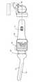
図1は、直腸内にはまるサイズの前立腺プローブの好適な実施例の斜視図である。プローブ10はヘッド11上に取り付けられた触覚センサ13を有している。触覚センサ13はそれが前立腺に押し付けられて前立腺に移動すると、触覚センサ13に与えられた力に応じた信号を生成する。プローブ10はハンドル16に接続されたシャフト12をさらに有している。制御ホイール17はハンドル16内に形成されている。二次元ディスプレイ15は、ディスプレイサポート14によってハンドル16に取り付けられている。もう一つの方法として、ディスプレイはプローブハンドル内に組み込むことができる。そのディスプレイまたは1台以上のディスプレイを1つのサポート上か1つ以上のサポート上に接続するか取り付けるかすることができる。電子ユニット(図1には図示していない)はハンドル16内に組み込まれている。FIG. 1 is a perspective view of a preferred embodiment of a prostate probe sized to fit within the rectum. The
前立腺の診察を行っている間、本発明にしたがって、プローブ10は直腸内に挿入され、直腸内でハンドル16を用いて操作される。実際には、ヘッド11が直腸内で動かされ、前立腺に対して押し付けられる。電子ユニットは触覚センサ13が与えた力に応じ触覚センサ13によって生成された電気信号を受信し、リアルタイムで前立腺の断面を特徴付ける圧力の輪郭を演算する。圧力の輪郭は、ディスプレイ15上で視覚化される。前立腺の診察の最初の段階においては、プローブ13の挿入深さは視覚センサ13の中央に近い位置となるように調節される。前立腺の診察の次の段階においては、前立腺は、前立腺およびその内部構造を機械的に画像化する演算を行うためにプローブ10の圧力応答と動作データを収集して所望の軌跡にしたがって触診される。 During a prostate examination, in accordance with the present invention, the
本発明の好ましい実施例においては、触覚センサ13は検査された前立腺に関するプローブの座標を決定する動作追跡システムとして使用される複数の加速度計を含む。本発明の他の好適な実施例においては、触覚センサ13は方向追跡システムに基づく磁力計を有する。その後、圧力応答データは、さらに下記に詳細に説明されているように、結果を機械的に画像化するためにリアルタイムに使用される。 In the preferred embodiment of the present invention, the
もう一つの方法として、プローブ10は対象の自然な開口を通じて対象の腺または組織に対して適用することによってどのような腺または組織に対してもまたそれに隣接する腺または組織にも用いることができる。プローブ10はまたドラッグデリバリーまたは他の種類の治療中、またはドラッグデリバリーまたは他の種類の治療後にも用いることができる。 Alternatively, the
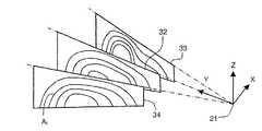
図2は、本発明の方法の具体例にしたがって前立腺23に対してプローブ10を周期的に押し付ける前立腺の診察中に触覚センサ13を備えたヘッド11の相対的な位置を例示した概略図である。まず、プローブ10のヘッド11は、前立腺の位置づれを最小化するために前立腺23に対して押し付けずにY軸に沿って直腸内に所望の深さまで挿入される。第2に、ヘッド11は、前立腺23の軸Yに沿うリアルタイムな断面画像をディスプレイ15上に入手するために、軌跡24上に位置される場所で前立腺23に押し付けられる。むしろ、触覚センサ13は前立腺23の軸方向長さよりも長い長さ寸法を持っている。好ましい実施例の触覚センサ13は、約25mmから約45mmの範囲で変動する一般的な平均的な前立腺の軸方向長さを超える長さ寸法を持つ。したがって、単一の圧縮の後に全体の前立腺により得られた圧力パターンを観察することができる。第3に、ヘッド11は前立腺23に接触させる触覚センサ13を有している。この触覚センサ13は触覚センサ13の中央に近い前立腺23の位置を調整するために軸Yに沿って動かされる。第4に、軌跡26に沿う複数の場所で前立腺23に対して押している間、前立腺23の一方の側から他方の側に横方向に移行するように、ヘッド11は軌跡25、26に沿って動かされる。軌跡26に沿う周期的な押し付けは、X軸に沿う前立腺の幾何学的な特徴を提供する。ヘッド11の振動といった他の方法は、軸Yに沿う機械的な画像化のリニアの解像度を増大させるため、前立腺23に対する同時押し付けを括約筋22からヘッド11の半径方向に加えることができる。 FIG. 2 is a schematic diagram illustrating the relative position of the
図3に示されるように、検査された前立腺の断面32,33および34を特徴付けるリアルタイムの内圧曲線は図2に示す位置の括約筋22を基点とする座標系21に示されるように前立腺に対してプローブを押し付けた結果として得られる。前立腺に対するすべての押し付けは、軸Zに沿う垂直方向で現される。断面32、33および34は、前立腺に対する各押し付けがリアルタイムで演算され、下記の手順に従って等しい圧力Aiのラインによってディスプレイ上に表される。 As shown in FIG. 3, the real-time internal pressure curve characterizing the examined prostate cross-sections 32, 33 and 34 is relative to the prostate as shown in the coordinate
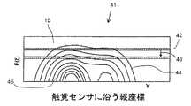
図4は、前立腺に対してプローブを押し付けている間、二次元の前立腺画像をリアルタイムに統合する方法を特徴づけるための具体例を示す形状図である。圧力レベル間の区別をさらに良好なものとするためには、触覚センサ13の圧力変換の異なる圧力レベルの表示には色スケールを用いることが効果的である。瞬間的な圧力応答データは色コード化ライン42として視覚化できる。座標YとF(ξ)を持つ地形図41のライン42の位置は、診察された前立腺に関連する触覚センサの位置を表している。触覚センサの位置と圧力変換器の圧力はプローブのヘッドが前立腺に対して押されると変化する。同様に、ライン42は、ライン42の前の位置の着色された跡を見せるように、矢印43によって示されるようにディスプレイ15上の座標F(ξ)に沿ってシフトされる。ディスプレイ15上に描かれたそれぞれのラインは、ライン42の位置の相違の視覚認知を向上させるために約1秒の時定数内でその明るさとコントラストを失って徐々に消える。 FIG. 4 is a shape diagram illustrating a specific example for characterizing a method for integrating two-dimensional prostate images in real time while a probe is pressed against the prostate. In order to further distinguish between the pressure levels, it is effective to use a color scale for displaying different pressure levels in the pressure conversion of the
ディスプレイ15上の座標Yは、図4に示すように触覚センサ13に沿う縦座標である。種々のパラメータはF(ξ)座標として用いることができる。この方法の好適な実施例においては、座標F(ξ)は、すべての圧力変換器又は触覚センサ13の変換器の部分からの平均圧力である。この方法の他の好適な実施例においては、座標F(ξ)は、Z座標の空間的な位置である(図3参照)。さらにこの方法の他の好適な実施例においては、座標F(ξ)は実行時間である。同一圧力のライン44は、二次元カラーディスプレイ15上に引かれうる。望ましくは、ライン44は前立腺の形状を表示するために所望のカラーを持ち、ライン45はより高い圧力に対応する前立腺内で増大した硬さによってカラー領域を表示する所望の第2のカラーを持つ。圧力データの圧力勾配解析は、前立腺の形状およびその内部構造を決定付けるために用いられる。 The coordinate Y on the
図5Aおよび5B、図6Aおよび6Bは、動作追跡システム50を基礎とする加速度計
を有する触覚センサ13を持つ図1に示した装置10の好ましい実施例をさらに詳細に示したものである。加速度計を基礎とする動作追跡システム50は、少なくとも2つの3軸加速度計53、55を有している。これらの加速度計53、55は重力と慣性の信号要素を区別するために使用できる。好ましくは、加速度計53は、前立腺を診察している間、加速度計53が括約筋の近くに位置され、プローブ10の角度測定の感度がリニアな加速度のそれよりもさらに良くなるように、ヘッド11に近いハンドル16に位置されることができる。加速度計55は、前立腺を診察する間、加速度計55がプローブ10の角度測定の感度がリニアな加速度のそれよりもさらに良くなるように、ヘッド11から最大の距離でハンドル16に位置されるのが好ましい。付加的な加速度計はシャフト12またはヘッド11に組み込むことができる。FIGS. 5A and 5B and FIGS. 6A and 6B show in more detail a preferred embodiment of the
前立腺をリアルタイムに機械的に画像化する装置の触覚センサ13はヘッド11に組み込まれる。触覚センサ13は圧力変換アレイ52を有している。圧力変換アレイ52は、好ましくは、弾性の合成物で覆われた、複数の圧電ポリマー変換器、またはマイクロマシンである圧電抵抗変換器、または容量性の変換器を有している。 A
カバー56は、ヘッド11とシャフト12とを覆う。カバー56は柔軟であることが好ましい。カバー56はリング57をハンドル16に固定することによって保持される。カバー56は使用後にプローブ10から取り外され、次の使用前に処分することができる。その後、新しいカバー56が、次の使用前に前立腺の診察の衛生管理のためにヘッド11とシャフト12に被せられる。例えば、カバー56はラテックスなどの薄い伸縮自在な素材で成形することができる。 The
好ましい実施例において、触覚センサ13は一般的に約25mmから45mmの間で変化する平均的な前立腺の軸方向長さを超える長さ寸法を有している。他の好ましい実施例においては、圧力検出ヘッド60は、図6Bに示されるように、電気的および機械的コネクタ62によってハンドル16に取り外し自在に接続された圧力変換器61を有している。圧力変換器61を含む圧力検出ヘッド60は使い捨てとすることができる。 In the preferred embodiment, the
好ましい他の実施例において、プローブヘッド65は、ハンドル16に固定して取り付けられ、圧力検出変換器61は図6Cに示される電気的および機械的コネクタ62およびロック64によってハンドル16に取り外し自在に取り付けることができる。本実施例では、圧力検出変換器61は使い捨てである。 In another preferred embodiment, the
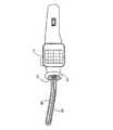
電子ユニット54、電源58とコンピュータポート59は、好ましくは、ハンドル16に納めることができる。電子ユニット54は触覚センサ13および加速度計53、55に接続される。電源58は電子ユニット54に接続される。ハンドル16に設置された制御ホイール17は、前立腺の診察処理の間、「開始」と「停止」信号を生成するために、および図6Aに示されているように調査モードを行うために使用される。調査モードにおいて、医師は種々の患者から受け取った蓄積データまたは外部コンピュータへの転送データをディスプレイ15で考察できる。ディスプレイ15は、図5に示される診察モードおよび図6Aに示される調査モードの2箇所でディスプレイ15を固定するヒンジ60が装備されたディスプレイ支持部14によってハンドル16に接続される。診察モードにおいては、ディスプレイ15は、前立腺の内部構造と前立腺の幾何学的パラメータの視覚化のために前立腺に対して押し付けている間、検査される前立腺の断面を特徴付ける圧力分布をリアルタイムで表示する。 The
図7Aには、本発明の方法の好適な実施例に関する動作追跡システム50を基礎とする加速度計の図が示されている。動作追跡システム50を基礎とする加速度計は、少なくとも2つの3軸加速度計53、55を含み、それらは前立腺の診察中プローブの動きに応じ
てアナログ信号を生成する。加速度計53と55の距離72および相対的な方向が知られている限り、三次元の軌跡は、加速度計53と55から受け取られたすべてのアナログ信号および固定された位置に関連するプローブヘッドの復元の2つを統合することによって測定することができる。FIG. 7A shows a diagram of an accelerometer based on a
加えて、改善された軌跡の精度は、次のことを考慮することによって決定される。3軸加速度計53は図の矢印72のように、前立腺に押し付けている間は括約筋の近くに位置されるので、軸Y1に沿った感度を有する加速度計53はプローブの仰角データ73を決めるための傾斜センサとして用いられる。感知軸Y1とY2を有する加速度計53,55からの同期したデータ解析は、仰角データ73の角加速度への影響を阻止することを可能にする。プローブの垂直方向の動きは、プローブの仰角の変化を考慮している加速度計53のZ1と加速度計53のZ2の2つの信号を統合することによって決定することができる。前立腺の断面(図4に示されている)を視覚化するための座標Zのより精密な決定のため、加速度計53の傾斜X1と加速度計55の傾斜X2から軸72に関する回転データを追加することができる。前立腺を押し付けているある場所からX軸(図2参照)に沿う他の場所へのプローブの横方向の変位を決定するために、加速度計からの異なる信号X1とX2がプローブの回転と仰角の変化を考慮することができるように統合される。触覚センサにおける最大圧力を有する位置に関連するプローブの軌跡を演算するために0動作加速を有する開始空間位置として、前立腺を押し付けている間、触覚センサの最大の圧力を有する位置を考慮することは有益である。In addition, the improved trajectory accuracy is determined by considering the following. Since the
方位追跡システム75を基礎とする磁力計の図7Bは、本発明の方法の好適な実施例を示している。方位追跡システム75を基礎とする磁力計は、前立腺の診察中、プローブを動かしているときに地球の磁場に関するプローブの位置の変化によってアナログ信号を生じる少なくとも1つの三軸磁力計74を含んでいる。プローブの位置がわかっている限り、前立腺を押し付けている相対的な場所が決定できる。もうひとつの方法として、動作追跡システムは、加速度計と磁力計の組み合わせ、またはジャイロスコープと加速度計の組み合わせを基礎とすることができる。 FIG. 7B of a magnetometer based on the orientation tracking system 75 shows a preferred embodiment of the method of the present invention. The azimuth tracking system 75 based magnetometer includes at least one three-
図8は、2次元または3次元の前立腺画像を演算する好ましい方法のフローチャートである。触覚センサ13の圧力変換アレイからの圧力データおよび動作追跡システム50からの位置データは、前立腺の診察の間にリアルタイムで取得される。圧力データセット81から触覚センサ13のすべての圧力変換器から取得した圧力に対応するアナログ信号は、A(pi,t)によって表される。ここで、piは時刻tで番号iを有する圧力変換器の圧力信号である。プローブの加速度と角方位を示すアナログ信号は、動作追跡システム50(B(bj,t)として表される動作データセット82である。ここで、bjは、時刻tで加速度計jに関連する信号である。)受信した前立腺診察中のプローブの動きに応じて生成される。動作追跡システム50を基礎とする加速度計は、上述のような傾斜センサとして用いられる加速度計からの応答を取得することができる。ブロック83において、圧力データセット81は、絶対圧力データP(i,t)に変換する。ここで、Pは時刻tで変換器iに与えられる力であり、圧力変換器52のキャリブレーションデータにしたがって演算される。FIG. 8 is a flowchart of a preferred method for computing a two-dimensional or three-dimensional prostate image. Pressure data from the pressure transducer array of the
ブロック84において、データP(i、t)は、前立腺の動きに関連する力測定のエラーおよび人為的な結果からノイズの発生を減少させるため、たとえばドーバー出版株式会社 T.J.リブリンの「近似関数の紹介」 ニューヨーク(1969)によって開示されているような従来の近似した方法で処理される。ブロック85において、訂正データP(i、t)は表示できるフォーマットで送信され、ディスプレイ15に表示される。ブロック86でのすべての動作は前立腺の診察の間にリアルタイムで生成される。 In
同時に、前立腺の診察データは、ブロック87で蓄積されている前記圧力データセットP(i、t)と動作データセットB(bjt)を含む。ブロック88において、触覚センサ13のそれぞれの圧力変換器52の座標が括約筋22(図2参照)を基点とする座標系で演算され、検査された前立腺の圧力応答のパターンP(x,y,z)が演算される。ブロック89において、勾配{P(x,y,z)}によって表される圧力変化応答のパターンはたとえばDレッドフェンおよびC.キャプベルによるマットラブ 5 ハンドブック
スプリンガ−バーラグ 株式会社 ニューヨーク(1998)によって開示されているような従来の方法によって前立腺の圧力応答のパターンから演算される。ブロック91において、前立腺の内側構造の機械的および幾何学的特徴が圧力変化応答から決定される。ブロック90では、前立腺P(x、y、z)の圧力応答パターンは、前立腺の幾何学的特徴を決定するために対象を圧力変化応答に関連する前立腺内部の堅い組織からずらすために訂正される。ブロック92では、前立腺の画像はブロック91で生成されたデータとブロック90で生成されたデータとによって統合される。同一圧力のほぼスムースな表面になったら、圧力変化応答のパターンを用いて前立腺内の硬さ分布を演算することができる。検査された前立腺の表面は、繰返しアルゴリズムによって前立腺の表面の法線に沿ってP(x、y、z)の二次導関数の最大値を演算することによって得ることができる。At the same time, prostate examination data includes the pressure data set P (i, t) and motion data set B (bj t) stored in
統合された画像は、ハンドル16に接続された二次元のまたはリニアのディスプレイ上に表示することができる。触覚センサ13に適用された圧力の平均レベル、その位置、圧力変換器の現実の軌跡およびプローブの動きに対する所望のパターンの軌跡は、同じディスプレイ上において前立腺画像上の面投影としてリアルタイムで表示することができる。 The integrated image can be displayed on a two-dimensional or linear display connected to the
図9は、図5において示されたプローブ10のハンドル16に設置された電子ユニット54の好ましい実施例の概略図である。複数の圧力変換要素93は触覚センサ13を形成する。圧力検出回路95は、前立腺の診察の間、触覚センサ13のそれぞれの圧力変換要素93に与えられた力を検出するために圧力変換要素93によって出力された個々の信号を増幅し変換するための複数の増幅器、変換器、積分器を形成する。複数の増幅器94は、前立腺に押し付けている間プローブの位置を検出するために、そしてある押し付け位置から別の押し付け位置へのプローブの移動を検出するために加速度動作追跡システム50のそれぞれの加速度計53,54によって出力された信号を増幅する。増幅器94と95からの増幅信号はマルチプレクサ96に与えられる。多重化された信号はアナログ−デジタル変換器97によってデジタル信号に変換され、プロセッサ98に供給される。プロセッサ98は、図3,4,8に示されている方法で説明したように、前立腺の診察中におけるそれぞれの圧力変換要素93の位置を演算するために、前立腺およびその周辺の組織の機械的な画像を近づけそして訂正するために、前立腺の幾何学的な特徴および損傷、小結節、硬い組織などのような前立腺内部構造の機械的な特徴を検出するために、前立腺の画像を統合するために、信号処理のために使用される。 FIG. 9 is a schematic diagram of a preferred embodiment of the
ディスプレイ15(ディスプレイスクリーンとコントローラを含む)は、プロセッサ98に接続される。従って、前立腺の診察過程と診察の最終結果が前立腺の画像としてリアルタイムで表示される。制御ホイール17は、前立腺の診察過程、データ分析およびデータ再調査をコントロールするためのドライバー99を介してプロセッサ98と接続される。プロセッサ98は、データと制御信号を送るためのアナログ−デジタル変換器97とマルチプレクサ96と通信する。記憶装置100は、格納されたデータを外部のコンピュータに転送するためのコンピュータポート59を有するプロセッサ98により生成された前立腺の診察結果を蓄えるための電子ユニット54において用いられうる。 A display 15 (including a display screen and a controller) is connected to the
上記の実施例は発明の原理を代表して応用することができる多くの可能な特定の実施例のうちのほんのわずかのものを説明していることがわかる。多くのそしてさまざまな装置はこれらの原理にしたがって当業者が発明の精神と範囲を逸脱せずにたやすく発明するこ
とができる。It can be seen that the above embodiments illustrate only a few of the many possible specific embodiments that can be applied on behalf of the principles of the invention. Many and various devices can be readily invented by those skilled in the art according to these principles without departing from the spirit and scope of the invention.
Claims (35)
Translated fromJapanese前記前立腺に重なる所望の軌跡に沿って前記触覚センサが移動している間、前記触覚センサから圧力応答データと動作データを電子ユニットが取得するステップと、
前記前立腺の断面を特徴づける1つまたは複数の内圧曲線を前記電子ユニットがリアルタイムで演算し表示するステップと、
前記圧力応答データと動作データから圧力変化応答のパターンを前記電子ユニットが演算するステップと、
前記圧力変化応答から前立腺の機械的な画像と前立腺の内部構造を前記電子ユニットが統合するステップと、
前記1つまたは複数の内圧曲線と前記機械的な画像をディスプレイに表示するステップと、
を含むことを特徴とする前立腺をリアルタイムで機械的に画像化する方法。Positioning a transrectal probe with a tactile sensor having a length dimension in excess of an average prostate axial length in the range of about 25 mm to about 40 mm in the rectum;
Anelectronic unit acquiring pressure response data and motion data from the tactile sensor while the tactile sensor is moving along a desired trajectory overlapping the prostate; and
Theelectronic unit calculates and displays in real time one or more internal pressure curves characterizing the cross-section of the prostate;
Theelectronic unit calculating a pressure change response pattern from the pressure response data and operation data;
Theelectronic unit integrating the mechanical image of the prostate and the internal structure of the prostate from the pressure change response;
Displaying the one or more internal pressure curves and the mechanical image on adisplay ;
A method for mechanically imaging a prostate in real time comprising:
前記触覚センサ中心下に前立腺を位置させるために初期の圧迫位置を調整するステップを含むことを特徴とする請求項2に記載の前立腺をリアルタイムで機械的に画像化する方法。Prior to the compression of the tactile sensor against the prostate,
3. The methodof mechanically imaging theprostate in real time according to claim 2, comprising adjusting an initial compression position to position the prostate under the tactile sensor center.
前記触覚センサからの圧力応答データと動作データを受信する電子ユニットと、
前記圧力応答データと動作データから前立腺の断面を特徴づける内圧曲線をリアルタイムで演算する手段と、
前記圧力応答データと動作データから前立腺の機械的な画像を演算する手段と、
前立腺とその内部構造の前記内圧曲線と前記機械的な画像を表示する前記ハンドルに接続されたディスプレイと、
前記電子ユニットを制御するために機能し前記ハンドルに取り付けられた制御ホイールと、
を有することを特徴とする前立腺をリアルタイムで機械的に画像化する装置。A probe having a head with a tactile sensor of a size that fits within the rectum and that is connected to the handle by a shaft and has a length dimension that exceeds the average axial length of the prostate in the range of about 25 mm to about 40 mm; ,
An electronic unit for receiving pressure response data and motion data from the tactile sensor;
Means for calculating in real time an internal pressure curve characterizing the cross section of the prostate from the pressure response data and the motion data;
Means for computing a mechanical image of the prostate from the pressure response data and motion data;
A display connected to the handle for displaying the internal pressure curve and the mechanical image of the prostate and its internal structure;
A control wheel functioning to control the electronic unit and attached to the handle;
A device for mechanically imaging the prostate in real time, characterized by comprising:
所望の軌跡に沿って前記触覚センサを移動している間、前記触覚センサから圧力応答データと動作データを電子ユニットが取得するステップと、
前記組織または腺の断面を特徴づける1つまたは複数の内圧曲線を前記電子ユニットがリアルタイムで演算しディスプレイに表示するステップと、
前記圧力応答データと動作データから圧力変化応答のパターンを前記電子ユニットがリアルタイムで演算するステップと、
前記圧力変化応答から前記組織または腺およびその内部構造の機械的な画像を前記電子ユニットがリアルタイムで統合するステップと、
前記組織または腺の検査中に前記1つまたは複数の内圧曲線と前記機械的な画像を前記電子ユニットがリアルタイムで表示するステップと、
を含むことを特徴とする組織または腺をリアルタイムで機械的に画像化する方法。Positioning a probe in atissue or gland or adjacent said tissue or gland;
Anelectronic unit acquiring pressure response data and motion data from the tactile sensor while moving the tactile sensor along a desired trajectory;
Theelectronic unit calculates anddisplays on a display in real time one or more internal pressure curves characterizing the cross section of the tissue or gland;
Theelectronic unit calculates a pressure change response pattern inreal time from the pressure response data and operation data;
Theelectronic unit integrating inreal time a mechanical image of the tissue or gland and its internal structure from the pressure change response;
Theelectronic unit displaying the one or more internal pressure curves and the mechanical image inreal timeduring the examination of the tissue or gland ;
A method for mechanically imaging a tissue or gland in real time comprising:
所望の軌跡に沿って前記触覚センサを移動している間、前記触覚センサから圧力応答データと動作データを取得する手段と、
前記組織または腺の断面を特徴づける1つまたは複数の内圧曲線をリアルタイムで演算し表示する手段と、
前記圧力応答データと動作データから圧力変化応答のパターンを演算する手段と、
前記圧力変化応答から前記組織または腺およびその内部構造の機械的な画像を統合する手段と、
前記組織または腺の検査中に前記1つまたは複数の内圧曲線と前記機械的な画像を表示する手段と、
を含むことを特徴とする組織または腺をリアルタイムで機械的に画像化するシステム。Means for applying a probe to atissue or gland, or adjacent said tissue or gland;
Means for obtaining pressure response data and motion data from the tactile sensor while moving the tactile sensor along a desired trajectory;
Means for computing and displaying in real time one or more internal pressure curves characterizing the cross section of the tissue or gland;
Means for calculating a pressure change response pattern from the pressure response data and the operation data;
Means for integrating a mechanical image of the tissue or gland and its internal structure from the pressure change response;
Means for displaying the one or more internal pressure curves and the mechanical imageduring examination of the tissue or gland ;
A system for mechanically imaging in real time a tissue or gland characterized by comprising:
Applications Claiming Priority (2)
| Application Number | Priority Date | Filing Date | Title |
|---|---|---|---|
| US09/819,419US6569108B2 (en) | 2001-03-28 | 2001-03-28 | Real time mechanical imaging of the prostate |
| PCT/US2002/009296WO2002082998A1 (en) | 2001-03-28 | 2002-03-28 | Real time mechanical imaging of the prostate |
Publications (2)
| Publication Number | Publication Date |
|---|---|
| JP2004527302A JP2004527302A (en) | 2004-09-09 |
| JP4177116B2true JP4177116B2 (en) | 2008-11-05 |
Family
ID=25228101
Family Applications (1)
| Application Number | Title | Priority Date | Filing Date |
|---|---|---|---|
| JP2002580806AExpired - Fee RelatedJP4177116B2 (en) | 2001-03-28 | 2002-03-28 | Real-time mechanical imaging of the prostate |
Country Status (5)
| Country | Link |
|---|---|
| US (1) | US6569108B2 (en) |
| EP (2) | EP1379171A4 (en) |
| JP (1) | JP4177116B2 (en) |
| CA (1) | CA2440849A1 (en) |
| WO (1) | WO2002082998A1 (en) |
Families Citing this family (106)
| Publication number | Priority date | Publication date | Assignee | Title |
|---|---|---|---|---|
| US6050943A (en) | 1997-10-14 | 2000-04-18 | Guided Therapy Systems, Inc. | Imaging, therapy, and temperature monitoring ultrasonic system |
| JP4052504B2 (en)* | 2002-01-29 | 2008-02-27 | 学校法人日本大学 | Apparatus for measuring elasticity characteristics of living tissue |
| WO2004105615A1 (en)* | 2003-05-30 | 2004-12-09 | Hitachi Medical Corporation | Ultrasonic probe and ultrasonic elasticity imaging device |
| JP3932485B2 (en)* | 2003-05-30 | 2007-06-20 | 株式会社日立メディコ | Ultrasonic diagnostic equipment |
| GB0313794D0 (en)* | 2003-06-14 | 2003-07-23 | Univ Dundee | Tactile sensor assembly |
| US20050228617A1 (en)* | 2004-04-02 | 2005-10-13 | Scott Kerwin | Methods and systems for tracking probe use |
| US7393325B2 (en) | 2004-09-16 | 2008-07-01 | Guided Therapy Systems, L.L.C. | Method and system for ultrasound treatment with a multi-directional transducer |
| US9011336B2 (en) | 2004-09-16 | 2015-04-21 | Guided Therapy Systems, Llc | Method and system for combined energy therapy profile |
| US7824348B2 (en) | 2004-09-16 | 2010-11-02 | Guided Therapy Systems, L.L.C. | System and method for variable depth ultrasound treatment |
| US20120165848A1 (en) | 2010-08-02 | 2012-06-28 | Guided Therapy Systems, Llc | System and method for treating cartilage |
| US10864385B2 (en) | 2004-09-24 | 2020-12-15 | Guided Therapy Systems, Llc | Rejuvenating skin by heating tissue for cosmetic treatment of the face and body |
| US8535228B2 (en) | 2004-10-06 | 2013-09-17 | Guided Therapy Systems, Llc | Method and system for noninvasive face lifts and deep tissue tightening |
| US8444562B2 (en) | 2004-10-06 | 2013-05-21 | Guided Therapy Systems, Llc | System and method for treating muscle, tendon, ligament and cartilage tissue |
| US11235179B2 (en) | 2004-10-06 | 2022-02-01 | Guided Therapy Systems, Llc | Energy based skin gland treatment |
| US20060111744A1 (en) | 2004-10-13 | 2006-05-25 | Guided Therapy Systems, L.L.C. | Method and system for treatment of sweat glands |
| JP2008522642A (en) | 2004-10-06 | 2008-07-03 | ガイデッド セラピー システムズ, エル.エル.シー. | Method and system for beauty enhancement |
| US9827449B2 (en) | 2004-10-06 | 2017-11-28 | Guided Therapy Systems, L.L.C. | Systems for treating skin laxity |
| US7758524B2 (en) | 2004-10-06 | 2010-07-20 | Guided Therapy Systems, L.L.C. | Method and system for ultra-high frequency ultrasound treatment |
| US11883688B2 (en) | 2004-10-06 | 2024-01-30 | Guided Therapy Systems, Llc | Energy based fat reduction |
| JP5094402B2 (en) | 2004-10-06 | 2012-12-12 | ガイデッド セラピー システムズ, エル.エル.シー. | Method and system for ultrasonic tissue processing |
| US8133180B2 (en) | 2004-10-06 | 2012-03-13 | Guided Therapy Systems, L.L.C. | Method and system for treating cellulite |
| US8690779B2 (en) | 2004-10-06 | 2014-04-08 | Guided Therapy Systems, Llc | Noninvasive aesthetic treatment for tightening tissue |
| US9694212B2 (en) | 2004-10-06 | 2017-07-04 | Guided Therapy Systems, Llc | Method and system for ultrasound treatment of skin |
| US11207548B2 (en) | 2004-10-07 | 2021-12-28 | Guided Therapy Systems, L.L.C. | Ultrasound probe for treating skin laxity |
| US11724133B2 (en) | 2004-10-07 | 2023-08-15 | Guided Therapy Systems, Llc | Ultrasound probe for treatment of skin |
| US7089807B2 (en)* | 2005-01-18 | 2006-08-15 | Chih-Ching Hsieh | Low-cost high precision twisting measuring device |
| AT9316U1 (en)* | 2005-05-04 | 2007-08-15 | Ami Gmbh | DEVICE FOR USE IN THE LIGATURE OF INTRAMULAR ARTERIES |
| US7819824B2 (en)* | 2005-05-06 | 2010-10-26 | Artann Laboratories Inc. | Method and a dual-array transducer probe for real time mechanical imaging of prostate |
| US7922674B2 (en)* | 2005-05-06 | 2011-04-12 | Artann Laboratories Inc | Method and device for real time mechanical imaging of prostate |
| US20060276726A1 (en)* | 2005-06-03 | 2006-12-07 | Holsten Henry E | Tissue tension detection system |
| GB0520596D0 (en)* | 2005-10-11 | 2005-11-16 | Sussex Dev Services Llp | Location and stabilization device |
| US7713216B2 (en)* | 2006-04-10 | 2010-05-11 | Intrapartum, Llc | Method for cervical dilation and/or measurement |
| US7527601B2 (en)* | 2005-12-29 | 2009-05-05 | Intrapartum Ventures, Llc | Cervimeter |
| US7811239B2 (en)* | 2005-12-29 | 2010-10-12 | Intrapartum, Llc | Cervical dilation measurement apparatus |
| US20070293792A1 (en)* | 2006-06-15 | 2007-12-20 | Sliwa John W | Prostate BPH and tumor detector also useable on other tissues |
| DE102007010046A1 (en)* | 2007-03-01 | 2008-09-04 | Siemens Ag | Prostate cancer detection apparatus |
| US20100256461A1 (en)* | 2007-05-01 | 2010-10-07 | Urodynamix Technologies Ltd. | Apparatus and methods for evaluating physiological conditions of tissue |
| US20150174388A1 (en) | 2007-05-07 | 2015-06-25 | Guided Therapy Systems, Llc | Methods and Systems for Ultrasound Assisted Delivery of a Medicant to Tissue |
| JP2010526589A (en) | 2007-05-07 | 2010-08-05 | ガイデッド セラピー システムズ, エル.エル.シー. | Method and system for modulating a mediant using acoustic energy |
| US8323199B2 (en)* | 2007-09-28 | 2012-12-04 | The University Of British Columbia | Method and apparatus for imaging the mechanical properties of tissue from an endocavity |
| US20090196459A1 (en)* | 2008-02-01 | 2009-08-06 | Perceptron, Inc. | Image manipulation and processing techniques for remote inspection device |
| US12102473B2 (en) | 2008-06-06 | 2024-10-01 | Ulthera, Inc. | Systems for ultrasound treatment |
| KR20110091832A (en) | 2008-06-06 | 2011-08-12 | 얼테라, 인크 | Tissue Imaging and Treatment Systems |
| WO2010048160A2 (en) | 2008-10-20 | 2010-04-29 | The Johns Hopkins University | Environment property estimation and graphical display |
| US20100137845A1 (en) | 2008-12-03 | 2010-06-03 | Immersion Corporation | Tool Having Multiple Feedback Devices |
| US8551002B2 (en)* | 2008-12-12 | 2013-10-08 | Immersion Corporation | Spatial array of sensors mounted on a tool |
| CA2748362A1 (en) | 2008-12-24 | 2010-07-01 | Michael H. Slayton | Methods and systems for fat reduction and/or cellulite treatment |
| US8652046B2 (en)* | 2009-01-15 | 2014-02-18 | Immersion Corporation | Palpation algorithms for computer-augmented hand tools |
| US8052622B2 (en)* | 2009-09-02 | 2011-11-08 | Artann Laboratories Inc | Methods for characterizing vaginal tissue elasticity |
| US8187208B2 (en)* | 2009-09-02 | 2012-05-29 | Artann Laboratories Inc. | Methods for assessment of pelvic organ conditions affecting the vagina |
| US8715186B2 (en) | 2009-11-24 | 2014-05-06 | Guided Therapy Systems, Llc | Methods and systems for generating thermal bubbles for improved ultrasound imaging and therapy |
| US9504446B2 (en) | 2010-08-02 | 2016-11-29 | Guided Therapy Systems, Llc | Systems and methods for coupling an ultrasound source to tissue |
| FR2966717B1 (en) | 2010-10-27 | 2013-07-26 | Commissariat Energie Atomique | STERILE PROTECTION WITH LIGHT GUIDES FOR MEDICAL PROBE AND METHOD OF MAKING SAME |
| JP5826478B2 (en)* | 2010-10-28 | 2015-12-02 | 日立アロカメディカル株式会社 | Tissue insertion type ultrasonic probe |
| KR101223209B1 (en) | 2010-12-10 | 2013-01-17 | 한국과학기술원 | Mechanical Loading based Apparatus and Method with compensating geometry information for measurement of diagnostic property of matter |
| WO2013105987A2 (en) | 2011-02-15 | 2013-07-18 | Hemosonics, Llc | Characterization of blood hemostasis and oxygen transport parameters |
| EP2491865A1 (en)* | 2011-02-24 | 2012-08-29 | Samsung Medison Co., Ltd. | Ultrasound system for providing image indicator |
| US20130012816A1 (en) | 2011-07-10 | 2013-01-10 | Guided Therapy Systems, Llc | Methods and systems for controlling acoustic energy deposition into a medium |
| WO2013012641A1 (en) | 2011-07-11 | 2013-01-24 | Guided Therapy Systems, Llc | Systems and methods for coupling an ultrasound source to tissue |
| US20150112230A1 (en)* | 2011-11-28 | 2015-04-23 | Remendium Labs Llc | Treatment of male urinary incontinence and sexual dysfunction |
| CN109259803B (en)* | 2011-12-16 | 2021-04-16 | 佩里梅特里克斯有限责任公司 | System and method for determining structural characteristics of an object |
| US9263663B2 (en) | 2012-04-13 | 2016-02-16 | Ardent Sound, Inc. | Method of making thick film transducer arrays |
| US9493342B2 (en) | 2012-06-21 | 2016-11-15 | Nextinput, Inc. | Wafer level MEMS force dies |
| EP2870445A1 (en) | 2012-07-05 | 2015-05-13 | Ian Campbell | Microelectromechanical load sensor and methods of manufacturing the same |
| KR20140008728A (en)* | 2012-07-11 | 2014-01-22 | 삼성전자주식회사 | Palpation apparatus and method using robot |
| US9510802B2 (en) | 2012-09-21 | 2016-12-06 | Guided Therapy Systems, Llc | Reflective ultrasound technology for dermatological treatments |
| CN104027893B (en) | 2013-03-08 | 2021-08-31 | 奥赛拉公司 | Apparatus and method for multifocal ultrasound therapy |
| WO2014146022A2 (en) | 2013-03-15 | 2014-09-18 | Guided Therapy Systems Llc | Ultrasound treatment device and methods of use |
| KR101495131B1 (en) | 2013-03-29 | 2015-02-26 | 김범기 | A prostate cancer diagnosis system using a pressure sensor and a prostate cancer diagnosis method thereof |
| EP3094950B1 (en) | 2014-01-13 | 2022-12-21 | Nextinput, Inc. | Miniaturized and ruggedized wafer level mems force sensors |
| WO2015160708A1 (en) | 2014-04-18 | 2015-10-22 | Ulthera, Inc. | Band transducer ultrasound therapy |
| US10925579B2 (en)* | 2014-11-05 | 2021-02-23 | Otsuka Medical Devices Co., Ltd. | Systems and methods for real-time tracking of a target tissue using imaging before and during therapy delivery |
| US9726647B2 (en) | 2015-03-17 | 2017-08-08 | Hemosonics, Llc | Determining mechanical properties via ultrasound-induced resonance |
| CN107848788B (en) | 2015-06-10 | 2023-11-24 | 触控解决方案股份有限公司 | Ruggedized wafer-level MEMS force sensor with tolerance trench |
| US20170065249A1 (en)* | 2015-09-08 | 2017-03-09 | Advanced Tactile Imaging Inc. | Methods and probes for vaginal tactile and ultrasound imaging |
| RU2615727C2 (en)* | 2015-09-29 | 2017-04-07 | Общество с ограниченной ответственностью "Уровест" | Uroflowmeter |
| USD801526S1 (en) | 2015-09-30 | 2017-10-31 | Sussex Development Services Llp | Rectal obturator |
| ES2939604T3 (en) | 2016-01-18 | 2023-04-25 | Ulthera Inc | Compact ultrasonic device having an annular ultrasonic array peripherally electrically connected to a flexible printed circuit board |
| JP7076735B2 (en) | 2016-05-03 | 2022-05-30 | テキサス メディカル センター | Tactile sensing device for lumbar puncture |
| PL3981466T3 (en) | 2016-08-16 | 2023-11-20 | Ulthera, Inc. | Systems and methods for cosmetic ultrasound treatment of skin |
| US11395593B2 (en) | 2016-09-14 | 2022-07-26 | Mor Research Applications Ltd. | Device, system and method for detecting irregularities in soft tissue |
| GB2559405A (en)* | 2017-02-06 | 2018-08-08 | Owlstone Med Ltd | Improvements in or relating to preparation of subjects for medical or veterinary examination |
| US11243125B2 (en) | 2017-02-09 | 2022-02-08 | Nextinput, Inc. | Integrated piezoresistive and piezoelectric fusion force sensor |
| EP3580539A4 (en) | 2017-02-09 | 2020-11-25 | Nextinput, Inc. | INTEGRATED DIGITAL FORCE SENSORS AND RELATED METHOD OF MANUFACTURING |
| US11510646B2 (en)* | 2017-04-05 | 2022-11-29 | Bk Medical Aps | Ultrasound imaging system probe cable and connector |
| US11221263B2 (en) | 2017-07-19 | 2022-01-11 | Nextinput, Inc. | Microelectromechanical force sensor having a strain transfer layer arranged on the sensor die |
| WO2019023309A1 (en) | 2017-07-25 | 2019-01-31 | Nextinput, Inc. | Integrated fingerprint and force sensor |
| WO2019023552A1 (en) | 2017-07-27 | 2019-01-31 | Nextinput, Inc. | A wafer bonded piezoresistive and piezoelectric force sensor and related methods of manufacture |
| WO2019079420A1 (en) | 2017-10-17 | 2019-04-25 | Nextinput, Inc. | Temperature coefficient of offset compensation for force sensor and strain gauge |
| US10383610B2 (en) | 2017-10-27 | 2019-08-20 | Intuitap Medical, Inc. | Tactile sensing and needle guidance device |
| WO2019084469A1 (en) | 2017-10-27 | 2019-05-02 | Renovia Inc. | Devices, systems, and methods for training pelvic floor muscles |
| WO2019090057A1 (en) | 2017-11-02 | 2019-05-09 | Nextinput, Inc. | Sealed force sensor with etch stop layer |
| WO2019099821A1 (en) | 2017-11-16 | 2019-05-23 | Nextinput, Inc. | Force attenuator for force sensor |
| MX2020006928A (en)* | 2017-12-30 | 2020-09-09 | Perimetrics Llc | Determination of structural characteristics of an object. |
| TWI797235B (en) | 2018-01-26 | 2023-04-01 | 美商奧賽拉公司 | Systems and methods for simultaneous multi-focus ultrasound therapy in multiple dimensions |
| US11944849B2 (en) | 2018-02-20 | 2024-04-02 | Ulthera, Inc. | Systems and methods for combined cosmetic treatment of cellulite with ultrasound |
| EP3873344A4 (en) | 2018-10-30 | 2022-06-29 | Renovia Inc. | Devices, systems, and methods for monitoring bladder function |
| US10962427B2 (en) | 2019-01-10 | 2021-03-30 | Nextinput, Inc. | Slotted MEMS force sensor |
| JP7171948B2 (en)* | 2019-05-17 | 2022-11-15 | コーニンクレッカ フィリップス エヌ ヴェ | Ultrasound system and method for tracking movement of an object |
| US12377293B2 (en) | 2019-07-15 | 2025-08-05 | Ulthera, Inc. | Systems and methods for measuring elasticity with imaging of ultrasound multi-focus shearwaves in multiple dimensions |
| DE102019007290A1 (en)* | 2019-10-21 | 2021-04-22 | Karl Storz Se & Co. Kg | Sensor-based surgery set and procedure |
| US12193830B2 (en) | 2020-09-22 | 2025-01-14 | Advanced Tactile Imaging Inc. | Method for characterization of the female pelvic floor with a biomechanical integrity score |
| ES2921203B2 (en) | 2021-02-15 | 2023-04-18 | Fundacion Para La Investigacion Del Hospital Univ Y Politecnico La Fe De La Comunidad Valenciana | Device for palpation of the prostate |
| JP2023148439A (en)* | 2022-03-30 | 2023-10-13 | 富士フイルム株式会社 | Ultrasonic diagnostic device and operation method thereof |
| KR20240120062A (en)* | 2023-01-31 | 2024-08-07 | 계명대학교 산학협력단 | Prostate cancer diagnosis system and method capable of predicting prostage cancer by digitally converting user's tactile sensation |
| CN116549008A (en)* | 2023-05-30 | 2023-08-08 | 无锡海斯凯尔医学技术有限公司 | Ultrasonic signal-based elastography system and method of use |
Family Cites Families (43)
| Publication number | Priority date | Publication date | Assignee | Title |
|---|---|---|---|---|
| US4132224A (en)* | 1977-01-12 | 1979-01-02 | Randolph Robert G | Durometer for indentible tissue and the like |
| US4423738A (en) | 1977-11-04 | 1984-01-03 | Sri International | Noninvasive blood pressure monitoring transducer |
| US4250894A (en) | 1978-11-14 | 1981-02-17 | Yeda Research & Development Co., Ltd. | Instrument for viscoelastic measurement |
| IL69471A (en) | 1983-08-12 | 1987-07-31 | Benjamin Gavish | Method and device for non-invasively monitoring the instantaneous fluctuations in the viscoelastic properties of a soft tissue |
| US4711248A (en) | 1983-12-01 | 1987-12-08 | Biokinetics, Inc. | Physiological pressure monitor |
| US4860761A (en) | 1985-04-12 | 1989-08-29 | Omron Tateisi Electronics Co. | Pulse wave detecting apparatus for blood pressure measurement |
| NL8502543A (en) | 1985-09-17 | 1987-04-16 | Sentron V O F | ELECTRONIC PRESSURE SENSITIVE ELEMENT MADE OF SEMICONDUCTOR MATERIAL. |
| US4802488A (en) | 1986-11-06 | 1989-02-07 | Sri International | Blood pressure monitoring method and apparatus |
| US4799491A (en) | 1986-11-06 | 1989-01-24 | Sri International | Blood pressure monitoring method and apparatus |
| US4869265A (en) | 1987-04-03 | 1989-09-26 | Western Clinical Engineering Ltd. | Biomedical pressure transducer |
| GB2205244B (en) | 1987-06-01 | 1991-04-03 | Blagoveshchensk G Med Inst | Device for cleansing the colon |
| US4809710A (en) | 1988-01-11 | 1989-03-07 | Williamson Jeffrey L | Multilumen manometer catheter |
| YU47190B (en) | 1988-02-19 | 1995-01-31 | Institut Za Opštu I Fizičku Hemiju | DEVICE FOR NON-INVASIVE ACOUSTIC TESTING OF ELASTICITY OF SOFT BIOLOGICAL MATERIALS |
| US5115808A (en) | 1988-02-19 | 1992-05-26 | Institute Of General And Physical Chemistry | Method and device for noninvasive acoustic testing of elasticity of soft biological tissues |
| US5107837A (en) | 1989-11-17 | 1992-04-28 | Board Of Regents, University Of Texas | Method and apparatus for measurement and imaging of tissue compressibility or compliance |
| US5247937A (en) | 1989-11-17 | 1993-09-28 | Board Of Regents, The University Of Texas System | Transaxial compression technique for sound velocity estimation |
| US5293870A (en) | 1989-11-17 | 1994-03-15 | Board Of Regents The University Of Texas System | Method and apparatus for elastographic measurement and imaging |
| US5474070A (en) | 1989-11-17 | 1995-12-12 | The Board Of Regents Of The University Of Texas System | Method and apparatus for elastographic measurement and imaging |
| US5078142A (en) | 1989-11-21 | 1992-01-07 | Fischer Imaging Corporation | Precision mammographic needle biopsy system |
| US5067491A (en) | 1989-12-08 | 1991-11-26 | Becton, Dickinson And Company | Barrier coating on blood contacting devices |
| FR2660543B1 (en) | 1990-04-06 | 1998-02-13 | Technomed Int Sa | METHOD FOR AUTOMATICALLY MEASURING THE VOLUME OF A TUMOR, IN PARTICULAR A PROSTATE TUMOR, MEASURING DEVICE, METHOD AND APPARATUS COMPRISING THE SAME. |
| FR2660732B1 (en) | 1990-04-06 | 1992-09-04 | Technomed Int Sa | TRANSLATABLE END ARM AND THERAPEUTIC TREATMENT APPARATUS, INCLUDING APPLICATION. |
| US5099848A (en) | 1990-11-02 | 1992-03-31 | University Of Rochester | Method and apparatus for breast imaging and tumor detection using modal vibration analysis |
| DE69216292T2 (en) | 1991-05-21 | 1997-06-05 | Jack Fisher | System and method for measuring mechanical properties of elastic materials |
| US5524636A (en) | 1992-12-21 | 1996-06-11 | Artann Corporation Dba Artann Laboratories | Method and apparatus for elasticity imaging |
| US5678565A (en)* | 1992-12-21 | 1997-10-21 | Artann Corporation | Ultrasonic elasticity imaging method and device |
| US5922018A (en)* | 1992-12-21 | 1999-07-13 | Artann Corporation | Method for using a transrectal probe to mechanically image the prostate gland |
| US5265612A (en) | 1992-12-21 | 1993-11-30 | Medical Biophysics International | Intracavity ultrasonic device for elasticity imaging |
| US5836894A (en)* | 1992-12-21 | 1998-11-17 | Artann Laboratories | Apparatus for measuring mechanical parameters of the prostate and for imaging the prostate using such parameters |
| US5785663A (en)* | 1992-12-21 | 1998-07-28 | Artann Corporation | Method and device for mechanical imaging of prostate |
| US6142959A (en) | 1992-12-21 | 2000-11-07 | Armed L.L.C. | Device for palpation and mechanical imaging of the prostate |
| US5423332A (en) | 1993-07-22 | 1995-06-13 | Uromed Corporation | Device and method for determining the mass or volume of a body part |
| US5402793A (en) | 1993-11-19 | 1995-04-04 | Advanced Technology Laboratories, Inc. | Ultrasonic transesophageal probe for the imaging and diagnosis of multiple scan planes |
| JPH0821732A (en)* | 1994-07-05 | 1996-01-23 | Data Tec:Kk | Attitude, azimuth, and position measuring apparatus |
| US5526820A (en) | 1994-09-19 | 1996-06-18 | Myelotec, Inc. | Catheter with integral pressure sensor |
| US5522399A (en) | 1994-09-26 | 1996-06-04 | Wilk; Peter J. | Catheterization device and associated assembly |
| US5989199A (en)* | 1996-11-27 | 1999-11-23 | Assurance Medical, Inc. | Tissue examination |
| US6063031A (en)* | 1997-10-14 | 2000-05-16 | Assurance Medical, Inc. | Diagnosis and treatment of tissue with instruments |
| US6179790B1 (en)* | 1997-10-20 | 2001-01-30 | Assurance Medical, Inc. | Layer of material for use with tissue examination device |
| AU6028299A (en)* | 1998-09-08 | 2000-03-27 | Catholic University Of America, The | Method and system for tactile imaging for breast cancer examination and detection of prostate cancer |
| US6190334B1 (en)* | 1999-05-24 | 2001-02-20 | Rbp, Inc. | Method and apparatus for the imaging of tissue |
| US6595933B2 (en)* | 2000-03-31 | 2003-07-22 | Artann Laboratories | Self-palpation device for examination of breast with 3-D positioning system |
| NL1018864C2 (en)* | 2001-08-31 | 2003-03-03 | Technologiestichting Stw | Device and method for generating three-dimensional images with tissue hardness information. |
- 2001
- 2001-03-28USUS09/819,419patent/US6569108B2/ennot_activeExpired - Lifetime
- 2002
- 2002-03-28EPEP02761982Apatent/EP1379171A4/ennot_activeWithdrawn
- 2002-03-28JPJP2002580806Apatent/JP4177116B2/ennot_activeExpired - Fee Related
- 2002-03-28WOPCT/US2002/009296patent/WO2002082998A1/enactiveApplication Filing
- 2002-03-28CACA 2440849patent/CA2440849A1/ennot_activeAbandoned
- 2002-03-28EPEP20100177745patent/EP2316335A1/ennot_activeWithdrawn
Also Published As
| Publication number | Publication date |
|---|---|
| EP1379171A4 (en) | 2007-01-17 |
| WO2002082998A1 (en) | 2002-10-24 |
| EP2316335A1 (en) | 2011-05-04 |
| CA2440849A1 (en) | 2002-10-24 |
| EP1379171A1 (en) | 2004-01-14 |
| US20020143275A1 (en) | 2002-10-03 |
| JP2004527302A (en) | 2004-09-09 |
| US6569108B2 (en) | 2003-05-27 |
Similar Documents
| Publication | Publication Date | Title |
|---|---|---|
| JP4177116B2 (en) | Real-time mechanical imaging of the prostate | |
| US6142959A (en) | Device for palpation and mechanical imaging of the prostate | |
| JP4997225B2 (en) | Dual array transducer probe for real-time mechanical imaging of the prostate | |
| US6595933B2 (en) | Self-palpation device for examination of breast with 3-D positioning system | |
| US5785663A (en) | Method and device for mechanical imaging of prostate | |
| US6620115B2 (en) | Apparatus and method for mechanical imaging of breast | |
| US5836894A (en) | Apparatus for measuring mechanical parameters of the prostate and for imaging the prostate using such parameters | |
| US5833633A (en) | Device for breast haptic examination | |
| US5922018A (en) | Method for using a transrectal probe to mechanically image the prostate gland | |
| US5505204A (en) | Ultrasonic blood volume flow rate meter | |
| US20070038152A1 (en) | Tactile breast imager and method for use | |
| US20110130685A1 (en) | Method and device for real time mechanical imaging of prostate | |
| EP2978378A1 (en) | Systems for measuring force and torque on ultrasound probe during imaging through strain measurement | |
| WO2007108028A1 (en) | Integrated pregnancy monitoring unit | |
| JP2005270351A (en) | Method and device for ultrasonic three-dimensional imaging | |
| Cheng et al. | Implementation of Wireless Knee Auscultation System Using Innovative Suction Device. |
Legal Events
| Date | Code | Title | Description |
|---|---|---|---|
| A621 | Written request for application examination | Free format text:JAPANESE INTERMEDIATE CODE: A621 Effective date:20050307 | |
| A131 | Notification of reasons for refusal | Free format text:JAPANESE INTERMEDIATE CODE: A131 Effective date:20080122 | |
| A601 | Written request for extension of time | Free format text:JAPANESE INTERMEDIATE CODE: A601 Effective date:20080422 | |
| A602 | Written permission of extension of time | Free format text:JAPANESE INTERMEDIATE CODE: A602 Effective date:20080430 | |
| A601 | Written request for extension of time | Free format text:JAPANESE INTERMEDIATE CODE: A601 Effective date:20080522 | |
| A602 | Written permission of extension of time | Free format text:JAPANESE INTERMEDIATE CODE: A602 Effective date:20080529 | |
| A521 | Request for written amendment filed | Free format text:JAPANESE INTERMEDIATE CODE: A523 Effective date:20080623 | |
| TRDD | Decision of grant or rejection written | ||
| A01 | Written decision to grant a patent or to grant a registration (utility model) | Free format text:JAPANESE INTERMEDIATE CODE: A01 Effective date:20080805 | |
| A01 | Written decision to grant a patent or to grant a registration (utility model) | Free format text:JAPANESE INTERMEDIATE CODE: A01 | |
| A61 | First payment of annual fees (during grant procedure) | Free format text:JAPANESE INTERMEDIATE CODE: A61 Effective date:20080821 | |
| FPAY | Renewal fee payment (event date is renewal date of database) | Free format text:PAYMENT UNTIL: 20110829 Year of fee payment:3 | |
| R150 | Certificate of patent or registration of utility model | Free format text:JAPANESE INTERMEDIATE CODE: R150 | |
| FPAY | Renewal fee payment (event date is renewal date of database) | Free format text:PAYMENT UNTIL: 20120829 Year of fee payment:4 | |
| FPAY | Renewal fee payment (event date is renewal date of database) | Free format text:PAYMENT UNTIL: 20130829 Year of fee payment:5 | |
| R250 | Receipt of annual fees | Free format text:JAPANESE INTERMEDIATE CODE: R250 | |
| R250 | Receipt of annual fees | Free format text:JAPANESE INTERMEDIATE CODE: R250 | |
| R250 | Receipt of annual fees | Free format text:JAPANESE INTERMEDIATE CODE: R250 | |
| R250 | Receipt of annual fees | Free format text:JAPANESE INTERMEDIATE CODE: R250 | |
| LAPS | Cancellation because of no payment of annual fees |