JP4176404B2 - Medical remote information system - Google Patents
Medical remote information systemDownload PDFInfo
- Publication number
- JP4176404B2 JP4176404B2JP2002203773AJP2002203773AJP4176404B2JP 4176404 B2JP4176404 B2JP 4176404B2JP 2002203773 AJP2002203773 AJP 2002203773AJP 2002203773 AJP2002203773 AJP 2002203773AJP 4176404 B2JP4176404 B2JP 4176404B2
- Authority
- JP
- Japan
- Prior art keywords
- patient
- identification code
- side device
- information
- display
- Prior art date
- Legal status (The legal status is an assumption and is not a legal conclusion. Google has not performed a legal analysis and makes no representation as to the accuracy of the status listed.)
- Expired - Fee Related
Links
- 238000004891communicationMethods0.000claimsdescription89
- 208000024891symptomDiseases0.000claimsdescription58
- 238000012546transferMethods0.000claimsdescription51
- 239000003814drugSubstances0.000claimsdescription35
- 229940079593drugDrugs0.000claimsdescription33
- 230000005540biological transmissionEffects0.000claimsdescription32
- 238000005259measurementMethods0.000claimsdescription29
- 238000000034methodMethods0.000claimsdescription29
- 238000004092self-diagnosisMethods0.000claimsdescription23
- 239000008280bloodSubstances0.000claimsdescription18
- 210000004369bloodAnatomy0.000claimsdescription18
- 230000000241respiratory effectEffects0.000claimsdescription17
- 239000007789gasSubstances0.000claimsdescription11
- CURLTUGMZLYLDI-UHFFFAOYSA-NCarbon dioxideChemical compoundO=C=OCURLTUGMZLYLDI-UHFFFAOYSA-N0.000claimsdescription8
- QVGXLLKOCUKJST-UHFFFAOYSA-Natomic oxygenChemical compound[O]QVGXLLKOCUKJST-UHFFFAOYSA-N0.000claimsdescription8
- 229910052760oxygenInorganic materials0.000claimsdescription8
- 239000001301oxygenSubstances0.000claimsdescription8
- 229910002092carbon dioxideInorganic materials0.000claimsdescription4
- 239000001569carbon dioxideSubstances0.000claimsdescription4
- 238000012790confirmationMethods0.000claimsdescription4
- 238000003860storageMethods0.000claimsdescription4
- 238000001514detection methodMethods0.000claimsdescription3
- 238000012360testing methodMethods0.000claimsdescription3
- 238000013507mappingMethods0.000claims1
- 208000006673asthmaDiseases0.000description53
- 208000017667Chronic DiseaseDiseases0.000description31
- 238000011282treatmentMethods0.000description21
- 230000002354daily effectEffects0.000description15
- 208000037265diseases, disorders, signs and symptomsDiseases0.000description11
- 230000036541healthEffects0.000description11
- 238000012545processingMethods0.000description11
- 230000006870functionEffects0.000description10
- 201000010099diseaseDiseases0.000description9
- 230000000694effectsEffects0.000description9
- 238000012544monitoring processMethods0.000description9
- 238000003745diagnosisMethods0.000description8
- 230000005713exacerbationEffects0.000description8
- 238000012986modificationMethods0.000description8
- 230000004048modificationEffects0.000description8
- 238000004590computer programMethods0.000description7
- 238000010586diagramMethods0.000description7
- 230000003203everyday effectEffects0.000description7
- 230000010365information processingEffects0.000description7
- 230000001575pathological effectEffects0.000description6
- 238000003759clinical diagnosisMethods0.000description5
- 210000004072lungAnatomy0.000description5
- 206010012601diabetes mellitusDiseases0.000description4
- 230000007170pathologyEffects0.000description4
- 238000003672processing methodMethods0.000description4
- 206010061218InflammationDiseases0.000description3
- 230000008859changeEffects0.000description3
- 208000023819chronic asthmaDiseases0.000description3
- 230000004054inflammatory processEffects0.000description3
- 238000009434installationMethods0.000description3
- 238000012806monitoring deviceMethods0.000description3
- 230000008569processEffects0.000description3
- 230000008054signal transmissionEffects0.000description3
- 208000019901Anxiety diseaseDiseases0.000description2
- 206010010071ComaDiseases0.000description2
- 208000000059DyspneaDiseases0.000description2
- 206010013975DyspnoeasDiseases0.000description2
- 125000002066L-histidyl groupChemical group[H]N1C([H])=NC(C([H])([H])[C@](C(=O)[*])([H])N([H])[H])=C1[H]0.000description2
- 208000037656Respiratory SoundsDiseases0.000description2
- 206010047924WheezingDiseases0.000description2
- 230000009798acute exacerbationEffects0.000description2
- 230000036506anxietyEffects0.000description2
- 238000013459approachMethods0.000description2
- 230000008901benefitEffects0.000description2
- 230000003247decreasing effectEffects0.000description2
- 230000006872improvementEffects0.000description2
- 230000003434inspiratory effectEffects0.000description2
- 230000004199lung functionEffects0.000description2
- 238000011422pharmacological therapyMethods0.000description2
- 238000003825pressingMethods0.000description2
- 230000000069prophylactic effectEffects0.000description2
- 230000009325pulmonary functionEffects0.000description2
- 230000000630rising effectEffects0.000description2
- 230000000087stabilizing effectEffects0.000description2
- 230000007704transitionEffects0.000description2
- 208000009079Bronchial SpasmDiseases0.000description1
- 208000014181Bronchial diseaseDiseases0.000description1
- 206010006482BronchospasmDiseases0.000description1
- 206010008469Chest discomfortDiseases0.000description1
- 206010011224CoughDiseases0.000description1
- 206010052804Drug toleranceDiseases0.000description1
- 102000001554HemoglobinsHuman genes0.000description1
- 108010054147HemoglobinsProteins0.000description1
- 208000005279Status AsthmaticusDiseases0.000description1
- 206010057362UnderdoseDiseases0.000description1
- 230000002159abnormal effectEffects0.000description1
- 230000005856abnormalityEffects0.000description1
- 229940124630bronchodilatorDrugs0.000description1
- 230000001914calming effectEffects0.000description1
- 230000001413cellular effectEffects0.000description1
- 238000006243chemical reactionMethods0.000description1
- 230000001684chronic effectEffects0.000description1
- 238000004140cleaningMethods0.000description1
- 238000013480data collectionMethods0.000description1
- 230000008034disappearanceEffects0.000description1
- 238000006073displacement reactionMethods0.000description1
- 238000009826distributionMethods0.000description1
- 238000005516engineering processMethods0.000description1
- 238000011156evaluationMethods0.000description1
- 230000026781habituationEffects0.000description1
- 208000019622heart diseaseDiseases0.000description1
- 208000027866inflammatory diseaseDiseases0.000description1
- 238000011866long-term treatmentMethods0.000description1
- 230000007774longtermEffects0.000description1
- 239000000463materialSubstances0.000description1
- 238000000465mouldingMethods0.000description1
- 210000003097mucusAnatomy0.000description1
- 230000002085persistent effectEffects0.000description1
- 238000011458pharmacological treatmentMethods0.000description1
- 238000002360preparation methodMethods0.000description1
- 238000012797qualificationMethods0.000description1
- 230000004202respiratory functionEffects0.000description1
- 230000029058respiratory gaseous exchangeEffects0.000description1
- 210000003296salivaAnatomy0.000description1
- 230000001932seasonal effectEffects0.000description1
- 208000013220shortness of breathDiseases0.000description1
- 241000894007speciesSpecies0.000description1
- 239000007921spraySubstances0.000description1
- 238000005507sprayingMethods0.000description1
- 230000006641stabilisationEffects0.000description1
- 238000011105stabilizationMethods0.000description1
- 230000002123temporal effectEffects0.000description1
- 229940126585therapeutic drugDrugs0.000description1
- 210000003437tracheaAnatomy0.000description1
- 238000002834transmittanceMethods0.000description1
- 238000011269treatment regimenMethods0.000description1
- XLYOFNOQVPJJNP-UHFFFAOYSA-NwaterSubstancesOXLYOFNOQVPJJNP-UHFFFAOYSA-N0.000description1
Images


Landscapes
- Measurement Of The Respiration, Hearing Ability, Form, And Blood Characteristics Of Living Organisms (AREA)
- Measuring And Recording Apparatus For Diagnosis (AREA)
- Medical Treatment And Welfare Office Work (AREA)
Description
Translated fromJapanese【0001】
【発明の属する技術分野】
本発明は、医用遠隔情報システムに関し、特に喘息や糖尿病のような慢性疾患の患者が自ら実行して疾患症状の安定化を図る一連の医学的処置である患者自己管理プログラムを、医療機関へ入院したり連日に亘り通院したりする必要なく、例えば患者の自宅にて実行する用途に最適な構成に関する。
【0002】
【従来の技術】
喘息や糖尿病のような慢性疾患は、長期的かつ緊密に症状のコントロールを継続して、症状の安定、平静化を図り、又、症状の急性増悪を未然に防ぐ必要がある。
【0003】
例えば喘息は気道の慢性持続性炎症性疾患であり、咳、喘鳴、胸部圧迫感、呼吸困難等の増悪を特徴とし、時として死に至ることもある。しかし、ピークフロー等のような肺機能の測定値を客観的に評価して増悪を予測し、適切な薬物の選択、薬物投与量の増減を行うことにより、増悪を未然に防止することが出来る。しかし慢性疾患であるがゆえに、患者の慣れや病状に対する認識不足や患者周囲の誤解など、症状をコントロールできない場合には急性増悪により緊急入院や死に至る危険もある。
【0004】
以下の記載は慢性の喘息を治療する際に固有の問題を、米国における事例に沿って示したものである。
【0005】
最近の事例は、慢性喘息の治療に用いるためのデータ収集および記録器具に多大な需要のあることを示唆している。米国の国立保健統計センターは、人口の5%近くの1200万人のアメリカ人が喘息にかかっていると推定している。喘息による罹病率および死亡率は1980年代に大きく増加した。その増加の原因はよく分かっていない。1980年代において、第一線の医療研究者は、喘息を、根本的には気管支痙攣としてではなく気道における炎症性反応としてみなすようになり始めた。そのため、彼らは新しい薬理学的療法である炎症を防ぐ薬物治療を推奨するようになった。さらに、自己管理プログラムの数多くの研究が、慢性喘息の長期治療における早期の前兆検出および患者・医者の協力管理の重要性を報告している。
【0006】
国立保健研究所によって設立された全国喘息教育プログラムは、1991年に、専門家パネル報告書:“喘息の診断および管理のためのガイドライン”を公表した。この専門家パネル報告書は、その序文の中で「喘息を患っている人々はその症状を抑え、喘息の起きるのを防ぎ、活動的になり、普通に呼吸をすることを期待できる。この報告書は臨床医および患者が喘息治療のこれらの目的を達成するのを手助けするためのガイドラインを示すものである。」と述べている。この報告書は薬理学的療法のための生活様式を勧め、炎症を抑える薬物治療の役割を強調し、投薬過多および過少投薬の危険について警告をしている。報告書は、喘息患者のための自己管理プログラムの成功を達成する際に患者、家族および医者の間の協力関係を育てることの重要性を強調している。
【0007】
ピークフローメータが出回るようになってもう何年にもなる。多くの臨床医が、毎日のPEFR測定によって喘息の発生を早期に警告することができることを認識している。しかし、毎日のピークフロー監視を勧める自己管理プログラムは、未だに標準ではなくむしろ例外的である。喘息治療の予防的アプローチを支持するにあたって、全国喘息教育プログラムは、喘息の管理に対して介入ではなくむしろ予防的アプローチを取り入れるように臨床医および患者に勧めている。
【0008】
ピークフローメータは、例えば、最大吸息状態から最大限の努力をして個人が肺から空気を吐き出すことのできる最大流量として定義されるピーク呼息流量(PEF)を測定するものである。PEFはリットル/分で測定される。最大3回まで試みて得られた最高値が、通常は手書きの表であるところのピークフロー日記に記入される。
【0009】
一般に個人用肺機能診断装置は、最大吸息状態から最大限の努力をして吐き出しの最初の1秒間に個人によって吐き出される空気の量として定義される強制的吐出し量(FEV1)を含む数種の呼吸パラメータを測定する。FEV1はリットル単位で測定される。
【0010】
医者は正確な呼吸状態データを入手できることによって:
(1)現在の薬物治療の投与方法の効果を検討する、
(2)上昇または下降する個人の最高PEFおよびFEV1の傾向である季節的パターンを検出する、
(3)長期間にわたっての気道の安定性を評価する、
(4)毎日のピークフロー監視を含む自己管理プログラムの順守度を評価する、
(5)良く管理プログラムに従った事への褒美として医者および/または親が用いることのできる奨励システムのための基準を設定する際にいくつかの利点を得る、ことができる。
【0011】
この専門家パネル報告書によれば、PEFおよびFEV1は、気道の不安定の早期の徴候を検出する際および薬物治療の投与方法の効果を評価する際に有用である。例えば、患者は気管支拡張剤を投与する前と後のPEFサンプルをとって、したがってその患者の激しい喘息の発作を治療する際のその薬の有効性を評価する基準とすることができる。
【0012】
専門家パネル報告書は、毎日のピークフロー監視を必然的に伴う患者の自己管理プログラムのサポートに向けてプライマリケアに従事する医師の指導を試みている。中程度または重い喘息の5才以上の患者には毎日ピークフロー値を測定することを勧めている。また、すべての患者および医師にその自己喘息管理プログラムにおいてピークフローメータおよび/または個人用肺機能診断装置を用いることを勧めている。
【0013】
NAEPの専門家パネルの議長 Albert L.Sheffer医学博士は喘息に対する多くの家庭管理プログラムにおける不完全さについて懸念を表明した;「毎日の治療を必要とするすべての喘息患者はピークフローメータで監視をされるべきである。このメータは現在はそれらの患者の25%未満にしか用いられていない。」喘息の診断および治療の高名な専門家 Guillermo R.Mendoza 医学博士は次のように述べている:「1978年以降、ピークフロー監視の価値についてのコンセンサスの増大にもかかわらず、米国においてプライマリケアに従事するものでその開業医療においてピークフローを採用したものは少数にすぎない。この国の危険度の高い喘息患者で、家庭にピークフローメータを持っているかまたはそれらをどのように有効に用いるかを知っているものはほとんどいない。」
米国政府の刊行物は次のように勧めている:「あなたの医者にピークフローメータを用いることについて質問をしなさい。ピークフローメータは、発作が何時起こるかを、あなたが徴候を感じる前であっても、あなたに教えることができる。徴候を感じる前に薬を服用することで発作を止めることができる。中程度または重い喘息の4才以上の人は、ピークフローメータを少なくとも毎日用いるべきである。」
上述の如くの喘息等の慢性疾患患者の管理において重要なことは、予め主治医が患者指導情報を記述したコントロール計画書を作成し、その計画書に従って計画の実行者が病状の発症/変化を事前に察知し、必要な場合及び必用な時期に投薬剤量の調整、適切な薬剤の選択、あるいは医師による処置を受ける等である。
【0014】
これらを適切に実施することにより、これら慢性疾患の病状をコントロールすることが可能となり、症状の消失、喘息患者の場合には呼吸機能の改善などが期待できる。
【0015】
ところで従来、上記のようなコントロール計画書に記載された管理プログラムを実行するために、患者が病院等の医療機関に入院して医師による病態観察、診断、処置を受ける方法があったが、長期に亘る入院治療は家庭における日常生活や職場での就労の機会を患者から奪うと共に、多大な経済的負担を患者、医療保険者等に強いる恐れがあった。
【0016】
また入院を行わず病院等に通院して上記の自己管理プログラムを実行しようとすると、ほぼ連日に通院を行う必要があるため、これまた上記の問題の本質的な解決とはならないとともに、診察すべき多数の外来患者を抱える医師により個々の患者に対する限られた診療時間の中では、本来緻密に実行されるべき患者自己管理プログラムの適切な実行が困難となる恐れもあった。
【0017】
そこで、上記の問題点を解決せんとして種々の構成が提案されており、例えば公知資料である特表平10−500598号公報には、上述したような喘息や糖尿病等の慢性疾患患者の長期管理に役立てるために、専用のセンサー装置(喘息疾患の場合には、ピークフローメータ等)を利用して患者自身が測定した臨床検査データ(生体情報)を、患者から遠隔の地にある情報処理センターに通信手段を介して送り、情報処理センターで収集、解析処理を行なったり、あるいはこの生体情報を医療従事者が観察して患者の症状を把握することにより、患者の容態観察を継続的に行なうシステムが開示されている(このシステムを以下では、従来のシステムとも呼ぶ)。
【0018】
【発明が解決しようとする課題】
しかしながら、上記した従来のシステムを含む従来技術に係る構成では本質的な解決が困難な、下記する如くの問題が存在した。
(1)多数の患者や、多数のモニタ装置を有する構成において、ひとりの患者の容態観察をひとりの特定の医療従事者が継続的に行なうことが容易に実現出来ない点。
【0019】
慢性疾患患者の容態、症状を確実に観察継続するためには、患者から採取した生体情報を通信手段を介して入手し、適切な能力、資格、経験を有する医療従事者(看護師、医師等)がこの生体情報を情報端末の表示画面上で観察するなどして、患者の容態を継続的、客観的に把握しつづける必要がある。
【0020】
一方、斯かる構成の従来のシステムを医療経済的な面で実現するためには、少数の慢性疾患患者の容態観察を少数の医療従事者が行なうよりもむしろ、より広いエリアをカバーして多数の患者を接続可能とし、また患者数に見合った人数の医療従事者が容態観察に従事できるよう複数の生体情報観察用モニタ手段を配設して、システムを構成することが望ましい。
【0021】
更に、慢性疾患患者の生体情報に基く容態観察は、不特定の医療従事者がその都度選ばれて交代で当たるのではなく、この患者の病歴、症状の特性等を熟知した特定の医療従事者が固定的、継続的に当たることが望ましいのであるが、上記したこれらの諸条件、すなわち多数の患者数を擁する一方、ひとりの患者に対しては特定の医療従事者が固定的に容態観察を行なう必要がある、という諸条件を容易に満足するシステム構成は知られていない。
(2)ひとりの慢性疾患患者の容態観察を継続的に行なう医療従事者の選定が容易かつ迅速に実行できない点。
【0022】
上記したように、慢性疾患患者の容態観察はひとりの医療従事者が固定的に専ら任ずるのが望ましいのであるが、その場合、上記した従来のシステムでは、実際に生体情報がセンターに送られて容態観察の実行が開始される以前に、ひとりの患者の容態観察に当たる特定の医療従事者を予め選定しておくことが望ましく、そうすることにより患者も安心して慢性疾患自己管理プログラムを開始することが出来る。
【0023】
ところが従来のシステムでは、例えば医療従事者が羅列されているリスト資料に基いて手作業でこの患者の容態観察担当者を選び、更に選んだ結果をこの医療従事者に連絡して以降の容態観察を実行する旨を指示する等、様々な手続きを経ることが必用であり、容易に且つ迅速に特定の医療従事者を選定することが出来ず、システムの円滑な運用が出来ない、という問題があった。
【0024】
本発明は、上記した状況に鑑みてなされたものであって、特に、(a)患者の症状を把握するための生体情報をこの患者から継続的に採取して通信路経由で送信する単数又は複数の患者側装置と、(b)患者側装置が送信した生体情報を逐次受信して蓄積し、且つ、この蓄積した生体情報を通信路経由で転送可能に構成したサーバ装置と、(c)サーバ装置から転送された生体情報を受信し、且つ、所定表示画面上に表示して患者の症状把握を可能とする単数又は複数の表示装置と、を備えた医用遠隔情報システムにおいて、患者側装置は、当該患者側装置を特定するための識別符号を通信路経由で送信する識別符号送信部を備え、サーバ装置は、患者側装置から送信された識別符号を受信して、単数又は複数の表示装置の内から選択した少なくとも1つの表示装置へ転送する識別符号転送部を備え、表示装置は、(1)サーバ装置から転送された識別符号を受信して記録する識別符号記録部と、(2)サーバ装置が蓄積する生体情報の中で、該表示装置の識別符号記録部に記録されている識別符号により特定される患者側装置から送信された生体情報の当該表示装置への転送を要求する転送要求信号を操作に応じて生成して、通信路経由でサーバ装置へ送信する転送要求信号送信部と、を備えたことにより、一人の患者の容態観察を、1台の同じ表示装置を用いて継続的に実行可能としたことを特徴とする医用遠隔情報システムとすることによって、ひとりの患者の容態観察をひとりの特定の医療従事者が専ら継続的に行なうことが容易に実現出来、更に、容態観察を継続的に行なう上記の特定の医療従事者の選定が容易に且つ迅速に実行可能であるので、患者の慢性疾患症状をより確実に安定化、平静化可能なシステム構成を高度な経済性の下に実現することが可能となる医用遠隔情報システムを提供することを目的とする。
【0025】
【課題を解決するための手段】
上記の課題を解決するために、本発明は、下記する1)〜14)の各構成を有する医用遠隔情報システムを提供する。
【0026】
1) (a)患者の症状を把握するための生体情報をこの患者から継続的に採取して通信路経由で送信する単数又は複数の患者側装置と、
(b)前記患者側装置が送信した生体情報を逐次受信して蓄積し、且つ、この蓄積した生体情報を通信路経由で転送可能に構成したサーバ装置と、
(c)前記サーバ装置から転送された生体情報を受信し、且つ、所定表示画面上に表示して前記患者の症状把握を可能とする単数又は複数の表示装置と、を備えた医用遠隔情報システムにおいて、
前記患者側装置は、当該患者側装置を特定するための識別符号を通信路経由で送信する識別符号送信部を備え、
前記サーバ装置は、前記患者側装置から送信された前記識別符号を受信して、前記単数又は複数の表示装置の内から選択した少なくとも1つの表示装置へ転送する識別符号転送部を備え、
前記表示装置は、(1)前記サーバ装置から転送された識別符号を受信して記録する識別符号記録部と、(2)前記サーバ装置が蓄積する生体情報の中で、該表示装置の前記識別符号記録部に記録されている識別符号により特定される患者側装置から送信された生体情報の当該表示装置への転送を要求する転送要求信号を操作に応じて生成して、通信路経由で前記サーバ装置へ送信する転送要求信号送信部と、を備えたことにより、一人の前記患者の容態観察を、1台の同じ表示装置を用いて継続的に実行可能としたことを特徴とする医用遠隔情報システム。
【0027】
2) 前記患者側装置の識別符号送信部は、
該患者側装置と前記サーバ装置との間の通信接続確認試験を実行する際に、前記識別符号を送信するよう構成したことを特徴とする前記1)に記載の医用遠隔情報システム。
【0028】
3) 前記患者側装置の識別符号送信部は、該患者側装置が前記生体情報を通信路経由で送信する際に、前記識別符号を送信するよう構成したことを特徴とする前記1)に記載の医用遠隔情報システム。
【0029】
4) 前記患者側装置は、移動可能、且つ移動した位置から前記生体情報を通信路経由で送信可能に構成したことを特徴とする前記1)乃至3)のいずれか1項に記載の医用遠隔情報システム。
【0030】
5) 前記患者側装置は、患者の呼吸特性についての生体情報を採取して通信路経由で送信するよう構成したことを特徴とする前記1)乃至4)のいずれか1項に記載の医用遠隔情報システム。
【0031】
6) 前記表示装置は、前記患者側装置が採取して送信した患者の呼吸特性についての生体情報に基いて「最大呼気流量測定値/自己最良呼気流量値」値を表示するよう構成したことを特徴とする前記5)に記載の医用遠隔情報システム。
【0032】
7) 前記表示装置は、前記患者側装置が採取して送信した患者の呼吸特性についての生体情報に基いて「所定時間内の呼気流量測定値」の変動値を表示するよう構成したことを特徴とする前記5)に記載の医用遠隔情報システム。
【0033】
8) 前記表示装置は、前記患者側装置が採取して送信した患者の呼吸特性についての生体情報に基いて「最大呼気流量測定値又は所定時間内の呼気流量測定値」の日内変動率を表示するよう構成したことを特徴とする前記5)に記載の医用遠隔情報システム。
【0034】
9) 前記患者側装置は、患者の血液中に含まれる特定気体の血中飽和度に関する生体情報を採取して通信路経由で送信するよう構成したことを特徴とする前記1)乃至8)のいずれか1項に記載の医用遠隔情報システム。
【0035】
10) 前記患者側装置は、前記特定気体として酸素の血中飽和度に関する生体情報を採取するよう構成したことを特徴とする前記9)に記載の医用遠隔情報システム。
【0036】
11) 前記患者側装置は、前記特定気体として二酸化炭素の血中飽和度に関する生体情報を採取するよう構成したことを特徴とする前記9)に記載の医用遠隔情報システム。
【0037】
12) 前記患者側装置は、所定薬剤に関する前記患者の服薬実行状況を検出して、検出結果を服薬実行情報として通信路経由で送信する服薬情報部を備え、
前記表示装置は、前記患者側装置が送信した前記服薬実行情報を前記所定表示部に表示するよう構成したことを特徴とする前記1)乃至11)のいずれか1項に記載の医用遠隔情報システム。
【0038】
13) (a)患者の症状を把握するための生体情報をこの患者から採取して通信路へ送信する生体情報送信部を備えた患者側装置と、
(b)前記患者側装置が送信した生体情報を受信して蓄積し、且つ、この蓄積した生体情報を通信路経由で転送可能に構成したサーバ装置と、
(c)前記サーバ装置から転送された生体情報を受信し、且つ、所定表示画面上に表示して前記患者の症状把握を可能とする表示装置と、を備えた医用遠隔情報システムにおいて、
前記サーバ装置は、前記患者側装置が自機の機能性能の自己診断を実行するよう、この患者側装置に指令するための自己診断実行指令情報を生成して通信路経由でこの患者側装置へ送信する指令情報送信部を備え、
前記患者側装置は、前記サーバ装置が送信した前記自己診断実行指令情報を通信路経由で受信した際に、(1)前記自己診断の実行制御と、(2)この自己診断の実行により得られた自己診断結果を前記生体情報送信部から通信路経由で前記サーバ装置へ送信する送信実行制御と、を行なう制御部を備えたことを特徴とする医用遠隔情報システム。
【0039】
14) (a)慢性疾患患者の症状を把握するための生体情報をこの患者から継続的に採取して通信路へ送信する送信部を備えた単数又は複数の患者側装置と、
(b)前記患者側装置が送信した生体情報を受信して継続的に蓄積し、且つ、この蓄積した生体情報を通信路経由で転送可能に構成したサーバ装置と、
(c)前記サーバ装置から転送された生体情報を受信し、且つ、所定表示画面上に表示して前記患者の症状把握を可能とする表示装置とを備えて、慢性疾患の治療において医療従事者と前記慢性疾患患者とが当該患者から採取された生体情報に基づき当該患者の疾患症状を客観的に把握し、把握した疾患症状に応じて所定の患者自己管理プログラムに基く医学的処置を当該慢性疾患患者自らが継続的に実行することを可能とする医用遠隔情報システムにおいて、
前記サーバ装置は、前記単数又は複数の患者側装置の中で、当該サーバ装置に対して最後に前記生体情報を送信してから現在までの経過時間が所定の閾値を超えた患者側装置、を抽出したリスト情報を生成するリスト情報生成部を備えたことを特徴とする医用遠隔情報システム。
【0040】
【発明の実施の形態】
以下、本発明の一実施の形態に係る好ましい実施例である、医用遠隔情報システム(喘息テレメディスンシステム)を、図1乃至図7に従い説明を行う。
【0041】
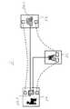
図1は本実施例の喘息テレメディスンシステムの構成図、図2は図1のシステムと細部の構成が異なる変形例である喘息テレメディスンシステムの構成図、図3乃至図5は図1のシステムが具備するピークフローメータの概観図、図6は図1のシステムが具備するサーバ装置の構成図、図7は図1のシステムが具備するモニタ装置が表示を行う生体情報の表示例である。
【0042】
尚、以下に一例として説明を行う医用遠隔情報システムは、特に喘息患者の病態を遠方よりモニタリングして患者が症状改善のための自己管理プログラムを実行することを助成する目的で構成されたものである故、以下、「喘息テレメディスンシステム」とも称している。
【0043】
この目的のもとに本システムは、下記に説明を行う構成のピークフローメータ1a−2を具備し、このピークフローメータ1a−2を用いて採取した生体情報(ピークフロー値等)を処理するよう構成がなされている。しかしながら本発明の実施に際しては上記の構成に限定されることはなく、喘息患者以外のための構成とすることも当然可能である。例えば糖尿病、心疾患等を患う患者のために適切な生体情報採取用のセンサ手段と、その生体情報を処理するための構成とを含むことが出来、その詳細な構成については、以下に説明する記載及び、公知の技術から容易に到達することが出来るものである。
【0044】
[喘息テレメディスンシステムの構成]
本実施例の喘息テレメディスンシステム1は、図1に示す如くの構成を有し、その主要な構成は、患者宅1aに設置されたピークフローメータ1a−2、ピークフローメータ1a−2から送信された生体情報を受けて医療機関1c側とモニタリングセンタ1d側とへ送信するサーバ装置1b、医療機関1c側に設置され、サーバ装置1bから送信された生体情報を自動受信して記録用紙に記録するファクシミリ装置1c−1、モニタリングセンタ1dに設置され、サーバ装置1bから送信された生体情報を受信して所定の表示部に表示するモニタ装置1d−1である。
【0045】
[ピークフローメータの構成]
患者宅1aに設置されたピークフローメータ1a−2は、喘息を患う患者1a−1が呼気を吹き込んで呼吸流量に関する生体情報を採取するための装置である。以下、ピークフローメータ1a−2の構成の詳細を、図3乃至図5に照らし合わせて説明する。
【0046】
以下の説明から明らかなように、このピークフローメータ1a−2は、喘息患者にとってその状態を監視するために有用なスタンドアロン型装置である。その側面図である図3(B)において、モニタハウジング60は、トッププレート62およびボトムプレート64を備えている。
【0047】
図3(A)および図3(C)はそれぞれトッププレート62の前面および後面図である。この前面は、その上にLCD表示装置50およびユーザ入力ボタン46が設けられている。次に図3(C)において、トッププレート62の底部分の突出部64は、円形部分64cおよびマウスピース格納部64mを含んでいる。この突出部は、円弧状部分66cとマウスピース当接部分66mとを有する突出部エッジ66と境界を接している。さらに、設置ポスト68が突出部64の円形部分64cの中央に配置されており、コイルハウジング69が円形部分64c上に中心から少し変位して配置されている。
【0048】
図4(A)および図4(B)は、センサチャンバ70の上および底面図である。図4(A)において、チャンバ70は、円筒状チャンバ部72およびマウスピース部74を備えている。円筒状チャンバ部72は円形断面を有し、円筒状部の上面の中央に軸コネクタ76が形成され、軸コネクタ76を中心としてかつそこから径方向に変位して円筒状チャンバ部74の上面に円弧形コイルハウジング開口77が形成されている。組になった通気口が円筒状チャンバ部74の上面および底面に形成され、円形にそって円筒状チャンバ部74の外周近くに配置される。
【0049】
図4(C)および図4(D)は、ピークフローメータ1a−2を、センサハウジング70を閉じた状態で示す。突出部66上の取り付けポスト68は軸コネクタ76と合わせられ、センサチャンバ70が設置ポストを中心として閉じた位置(図示)から開いた位置(点線)に回転するようになっている。閉じた位置においては、マウスピース部74の開口が、突出部エッジ66のマウスピース当接部66mに当接してマウスピースを密閉する。開いた位置においては、患者は、その唇をマウスピースの開口に密着させ、空気流量を測定するためにチャンバに息を吹き込む。マウスピースは開閉位置の間を回転して、糸屑や破片を寄せ付けないのに役立っている。
【0050】
ところで、このピークフローメータ1a−2は、患者の呼吸データ、具体的には、ピークフロー値、即ち努力性呼出中に生じる最大フロー速度(以下、PEF)、あるいは努力呼気フローの最も一般的な指標である一秒量(以下、FEV1)、即ち最大吸気位から1秒間に呼出しうる最大空気量を測定し、データ及び測定日時を記憶し、機台番号や患者ID等患者1a−1を識別する符号と共に、電話回線等の通信路を介して送信する機能を有する。尚、上記したFEV1は、1秒間以外の所定時間内の最大空気量を測定した値に置き換えることも勿論可能である。
【0051】
ここで、上記したPEFおよびFEV1を測定するためのセンサの動作を、図5に照らし合わせて説明する。図5は円筒状チャンバ部72の横断面図である。ボトムおよびトップ内部面は、その中にベアリング受けカップ80tおよび80bが形成されている。ローター82は中央ポスト84を含み、ローターブレード86がそこから延びている。ローターブレード86は円筒状部72の円筒状側面近くに配置された垂直羽根88を含んでいる。先細軸受90tおよび90bが中央ポスト84の頂部と底部に形成され、ベアリング受け切り欠き80tおよび80bと合わさっている。中央ポスト82は図において横断面で示した少なくとも1個の棒磁石92を含んでいる。
【0052】
センサ内のローターは2つのサブアセンブリ、4枚ブレードのローター82と、磁石の長軸がローターの回転の軸に垂直になるようにローターのシャフトに永久に嵌め込まれる円筒状磁石92とを含む。ローターのシャフトの各先端88は、センサの頂部および底部サブアセンブリの内部面における小カップ80tおよび80bに緩く嵌められている。この結合においては、ベアリングはなく、ローターのシャフトの先端がこれらの小さなカップに収まる。
【0053】
患者1a−1がセンサチャンバに息を吹き込むと、ローターはコマのように回転し、そのシャフトの先端がカップ内で回転する。唾液または粘液がこれらの回動点の中または回りに付着した場合、ローターシャフトの先端がカップへ緩く嵌められていることが、蛇口からの水の流れによる容易な洗浄を可能にしている。
【0054】
患者1a−1がセンサハウジング70のマウスピース開口に息を吹き込むと、空気の流れはチャンバ70の円筒状側壁に対して向けられ、ブレード88に当たってローターの回転を引き起こす。ローターの各1回転に対して約30ミリリットルの空気がチャンバ70を通過する。空気は通気口78を介して外に出て、背圧が上昇するのを防いでいる。センサチャンバ72は、患者がそこに息を吹き込んだ場合に渦巻状の流れを生じるように機械的に設計されている。また、4枚ブレードのローターは、ちょうどコマのようにその最大主慣性モーメントで回転し、これによって、軸受けの潜在的なガタおよび引きずりを無くしている。
【0055】
さらに図5において、コイル69は棒磁石92が一回転をするごとに2パルスを生成する。これらのパルスは増幅、ろ波されてディジタル遷移を生じる。各遷移間の時間は、アプリケーションソフトウェアを実行するマイクロコントローラ(図示しない)によって処理される。PEFおよびFEV1が計算され、データ記録の一部としてRAM(図示しない)に格納される。
【0056】
図5から、回転の軸受が、精度の高い嵌合を必要としない「スロッピー(sloppy)ベアリング」であることがわかる。したがって、ピークフローメータ1a−2のすべての部分を、低コストの工程を利用してプラスチックで製造することができる。また、成形工程により一貫性のある部品が製造され、それにより極めて高い装置間の再現性を確保し、異なるセンサチャンバ(マウスピース)を任意のモニタハウジングで用いることを可能にしている。さらに、マウスピースは、使用現場における校正を必要としない。
【0057】
「スロッピーベアリング」は、パルスの間で小さなタイミングエラーを生じる。測定は数個のパルスに基づいて行われ、したがってそのような影響は平均化される。さらに、マイクロコントローラは、ディジタル補償プログラムを実行し、慣性モーメントが零で無いことの影響を取り除く。このプログラムは、ローターおよびチャンバの実際の回転力学および空気力学に合わせたいくつかのパラメータに基づいている。
【0058】
ローター80は、中央ポストを中心として回転させられた場合のコマのような回転特性および非ゼロ慣性モーメントを有している。マイクロコントローラは、補償プログラムを実行して、非ゼロ慣性モーメントの影響を取り除き、PEFおよびFEVの実際の値を計算する。このプログラムはローターの動きを計算するのに伴う物理的原則に基づいており、ローターの実際の回転に合わせたいくつかのパラメータを含んでいる。
【0059】
またピークフローメータ1a−2内部には、採取したPEF等の生体情報を送信すべきサーバ装置1bの電話番号を予め記憶する記憶部(図示しない)を具備して、モジュラージャックをつなぎ、所定の操作ボタンを押圧操作するのみで、患者1a−1は電話番号をダイアルすることなくサーバ装置1bに交信接続し、ピークフローメータ1a−2内に蓄積されていた生体情報をサーバ装置1bに送信することが出来る。更に無線通信や携帯電話機能を備えることにより、モジュラージャックの接続自体も省略することが出来る。
【0060】
尚、患者宅1a、サーバ装置1b、モニタリングセンタ1d、及び医療機関1cの間で通信を行うために設けられた通信路の全て、あるいは少なくとも一部は、有線公衆電話回線、携帯電話回線、PHS回線、ISDN回線、有線又は無線のローカルエリアネットワーク回線、衛星通信回線、CATV回線、インターネット通信網等、種々の通信回線を用いて構成可能である。
【0061】
またピークフローメータ1a−2は、患者宅においてのみ生体情報の送信を行なうばかりでなく、通信路を介してサーバ装置1bへ生体情報を送信可能である位置へ移動して、この位置から生体情報を送信することも出来る。
【0062】
すなわち、電話回線のジャックを配設した、患者宅以外の場所、あるいは無線通信路を用いる場合には無線通信可能な任意の位置から生体情報を送信することがかのうであるので、患者が旅行等で移動した際にも移動先でテレメディスンを実行することが出来、患者のQOLが更に向上する効果がある。
【0063】
更にピークフローメータ1a−2内には、上記した患者識別ID等の、このピークフローメータ1a−2や患者を特定するための識別符号を内部に記憶し、操作に応じてこの識別符号を通信路経由で送信する識別符号送信部を有している。
【0064】
[サーバ装置の構成]
次に、図6および図7に従い、サーバ装置1bの構成を説明する。
サーバ装置1bは、図6の構成図に示す如く、その内部に第1のインターフェース部1b−1、中央処理部1b−3、データベース部1b−4、第2のインターフェース部1b−2、第3のインターフェース部1b−5を備えている。
【0065】
第1のインターフェース部1b−1はピークフローメータ1a−2が送信して電話回線等の所定の通信路1e1を介して受信した生体情報に所定の変換を行ない、中央処理部1b−3へ送信する。中央処理部1b−3は第1のインターフェース部1b−1から受信した生体情報をデータベース部1b−4に蓄積すると共に、データベース部1b−4に蓄積されている生体情報を読み出して、医療機関1c及びモニタリングセンタ1dで病態観察を行なえるように加工し、例えば予め定めた所定時刻に毎日、第2のインナーフェース部1b−2を通じて医療機関1cへ、第3のインターフェース部1b−5を通じてモニタリングセンタ1dへ送信を行なう。
【0066】
あるいは又、サーバ装置1bは毎日定時的に生体情報をモニタリングセンタ1dへ送るのではなく、モニタリングセンタ1dより要求を受けた際に要求された患者の生体情報を当該モニタリングセンタ1dへ送るように構成してもよい。上記の構成を実現するためには、ピークフローメータ1a−2は、複数の喘息患者それぞれに対して設けられた複数のピークフローメータであり(図示しない)、又、各ピークフローメータは各患者に固有な識別IDを付して生体情報をサーバ装置1bへ送信し、サーバ装置1bが各識別ID毎に蓄積し管理するのを可能とする構成とする。そしてモニタリングセンタ1dは病態観察を行なおうとする患者の識別IDを含む要求信号をサーバ装置1bへ送って生体情報の送信を求める。
【0067】
尚、上記した患者識別IDに代えて、複数のピークフローメータ1a−2のそれぞれに固有に付与されたピークフローメータ識別ID(機台番号)でもよいし、あるいはインターネット通信網を用いて患者の生体情報を送信する構成の場合には、各ピークフローメータ1a−2の通信路への接点に付与されたIPアドレスでもよく、その他の構成もまた可能である。この点は以下も同様である。
【0068】
さて、医療機関1c側に送られる生体情報は第2のインターフェース部1b−2から所定通信路1e2を経由して送信がなされる。またモニタリングセンタ1d側に送られる生体情報は第3のインターフェース部1b−5から所定通信路1e3を経由して送信がなされる。
【0069】
またデータベース部1b−4は、上述のように、患者1a−1を識別するための識別IDである、例えば患者IDやピークフローメータ1a−2の機台番号毎に生体情報を記憶蓄積することができ、上記したようにピークフローメータ1a−2が送信する生体情報には生体情報を採取した日時に関するデータも含まれているので、ピークフローメータ1a−2が順次送信する生体情報を、患者毎に経時的に変化する生体情報としてデータベース部1b−4に蓄積可能である。
【0070】
斯かる構成を有するサーバ装置1bは、患者1a−1についての生体情報の経時的変化を読み取り可能なようなグラフのデータを中央処理部1b−3において作成して医療機関1c側のファクシミリ装置1c−1に送信して記録用紙に記録させ、又、モニタリングセンタ1d側のモニタ装置1d−1に送信して所定の表示部に表示させることが出来る。
【0071】
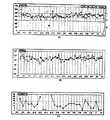
上記した生体情報のグラフは例えば図7に示す如くの構成を有する。
即ち、図7(A)に示すように、横軸に測定日付、縦軸に「最大呼気流量測定値」をとり、毎日の測定値をプロットしたグラフとすることが出来る。また、サーバ装置1bのデータサーバ1b−4には当該患者の「最大呼気流量の自己最良値」が予め測定記録されている。そして中央処理部1b−3は現在測定された「最大呼気流量測定値」と上記の予め記録されていた「最大呼気流量の自己最良値」との比を算出し、算出した比の大きさに応じてグラフの領域をI、II、IIIという3領域に分けて表示することが可能である。これらの3領域を表示するにあたっては、領域Iを緑色、領域IIを黄色、領域IIIを赤色としてモニタ装置1d−1に表示させ、日々のプロット値がどの領域中にあるかを明示的に検知可能なように表示させても良い。
【0072】
上記した3領域の表示方法においては、それぞれの生体情報が、患者がその気道がきれいなときに通常到達する最高のピークフローレベルとして定義される各個人の最高値に対するパーセントに応じた領域内にプロットされる。これらの領域は、上記のごとく、交通信号に類似−すなわち緑、黄色、および赤−しており、覚えやすくなっている。各領域は個人の最高値に対するパーセントを見分けるのに役立つ。緑領域(領域I)は個人ベストの80%−100%、黄色領域(領域II)は50%−80%、赤領域(領域III)は50%未満である。個人の最高値および各領域間の境界は、患者が調整することのできる適合可能な値である。どのような調節も医師の特別な許可によってなされるべきものである。
【0073】
したがって、利用者は、測定された値が赤、黄色、または緑ゾーンあるかを直ちに知らされ、数値について精通または理解をする必要はない。
【0074】
またサーバ装置1bが生成するグラフのデータは、上記に説明した図7(A)の如くの態様の他に、下記する図7(B)あるいは図7(C)に示す如くの態様とすることも可能である。
【0075】
即ち、図7(B)に示すグラフは、上述のFEV1、即ち最大吸気位から1秒間に呼出しうる最大空気量を縦軸とし、横軸を測定日時としてプロットしたものである。喘息を患う患者においては息の吐き出し方が一定の傾向でないと問題があるとされる。従って図7(B)のグラフを用いて、前回の測定値と比較したFEV1の上昇量あるいは下降量(上昇あるいは下降の差分量)が予め定めた所定値を超えるときに異常と判断される。表示画面に表示されたFEV1のグラフの差分量を直接読み取ったり、あるいはこの差分量が所定値を超えたときに警告表示が画面上に現れるなど、種々の方法により、症状の増悪時等の非正常値が生体情報に含まれる際には明示的に示すことが出来る。
【0076】
又、図7(C)に示すグラフは、上記のPEF、FEV1、あるいはその他の呼吸流量に関わる測定値の日内変動率を縦軸に、測定の日時を横軸にプロットしたものである。ここで日内変動率は、例えば午前と午後とを含む複数の測定値の内、最大値と最小値との比率から求めることが出来る。一例として、20%を日内変動率を判定の基準値とし、これを超える場合は異常と判断する。図7(C)に示すグラフには、この20%の基準ラインを一点鎖線で表示してあるので、プロットされた測定値がこの基準ラインを超えるか否かにより、症状の増悪時等の非正常値が生体情報に含まれるか否かを明示的に示すことが出来る。
【0077】
[ファクシミリ装置の構成]
次に、医療機関1c側に設置されたファクシミリ装置1c−1について説明する。サーバ装置1bから送信された生体情報(測定値、及び/又は、測定値に基づいて作成したグラフ)を自動的に受信して所定の記録用紙に記録するために、本システムでは汎用のファクシミリ装置1c−1を用いている。そして記録用紙に記録された生体情報を用いて医師が当該患者の臨床診断を実行可能である。
【0078】
又、サーバ装置1bから送信される生体情報を自動的に受信して記録媒体に記録するための手段としては、上記した汎用のファクシミリ装置1c−1の他に、公知技術に係る様々な構成を用いることが可能である。例えば、サーバ装置1bとネットワーク回線を介して接続するパーソナルコンピュータとプリンタ装置との組み合わせ、あるいは同じくパーソナルコンピュータとその内部、又は外部に設けられた電子的あるいは電磁的媒体記録再生装置との組み合わせでもよい。
【0079】
あるいは又、医師のもとにある携帯電話等の情報端末に対してサーバ装置1bより無線通信回線を経由して生体情報が配信され、配信後、携帯電話内に蓄積記憶された生体情報を医師が所望のタイミングで呼び出して内容を確認する構成もまた可能である。
【0080】
さらに又、サーバ装置1bはインターネットプロバイダが保有するメールサーバ宛に電子メールとして生体情報を送信し、医師は、所望のタイミングで自己のもとにあるパーソナルコンピュータ、携帯電話等の手段を用いて上記のメールサーバの自己のメールアドレスをチェックし、サーバ装置1bより送信されていた生体情報を取得する構成もまた可能である。上記した如くの各変形例は図示はしないものの本発明の実施形態として包含されるものである。
【0081】
[モニタ装置の構成]
次に、モニタリングセンタ1dに設置されて生体情報のリアルタイムな監視を行うためのモニタ装置1d−1の構成を説明する。
本システムにおいて、モニタ装置1d−1は、汎用のパーソナルコンピュータと、このパーソナルコンピュータに実装された、サーバ装置1bから送信された生体情報に基づき図7(A)〜図7(C)に示したようなグラフを上記パーソナルコンピュータの表示部(モニタ画面)に表示するためのコンピュータプログラムとを含んでいる。このコンピュータプログラムは、汎用のワードプロセッサプログラム、表計算プログラム、図形表示用プログラム等であってもよいし、あるいは本システムのために設計がなされた専用のコンピュータプログラムであってもよい。
【0082】
上記したパーソナルコンピュータとコンピュータプログラムとの組み合わせの他に、例えば携帯電話、PHS、モバイル携帯電子端末等の可搬型の受信および表示装置を用いることも可能である。
【0083】
これら可搬型の装置を用いれば、看護婦等の医療従事者がこの装置を携行して各患者宅を巡回して、よりきめの細かい病態観察と自己管理プログラム実行のための助成とを行うことが出来るとともに、多数の可搬型装置を比較的小規模のサーバ装置1bが統括して生体情報の配信がおこなわれるので、モニタリングを行うべき対象の患者数が多数である場合でも大規模なモニタリングセンタ1を設ける必要が無くなり、比較的低廉な設置運営コストでシステムを構成できる利点もある。
【0084】
またモニタ装置1d−1は単数または複数が本システム1内に配置されて患者の容態観察等を実行可能とするものであるが、図1においては1台のモニタ装置1d−1のみを図示している。
【0085】
複数のモニタ装置1d−1を有するシステム構成の場合には、広域(例えば、日本全国)を管轄エリアとするサーバ装置1bが設けられるのに対して、各地域毎にモニタリングセンタ1dが設けられてモニタ装置1d−1が配設される構成としてもよい。
【0086】
更に、モニタ装置1d−1の内部には、サーバ装置1bから転送された識別符号(患者識別ID等)を受信して記録する識別符号記録部が設けられている。
【0087】
更にまた、モニタ装置1d−1の内部には、サーバ装置1bが蓄積する生体情報の中で、上記の識別符号記録部に記録されている識別符号により特定されるピークフローメータ1a−2から送信された生体情報のこのモニタ装置1d−1への転送を要求する転送要求信号を、操作に応じて生成して通信路経由でサーバ装置1bへ送信する転送要求信号送信部を有している。
【0088】
上記した識別符号記録部、及び転送要求信号送信部のより詳細な機能については、後記する。
【0089】
[本システムが有するその他の構成]
上記した各構成の他に、本システム1においては、患者宅1a、医療機関1c、及びモニタリングセンタ1dには、相互に通話を行うための手段として、固定電話機1a−3、1c−2、1d−2が固定電話回線1e4、1e5、1e6を介して設けられている。患者1a−1と、医療機関1cの医療従事者等と、モニタリングセンタ1dの指導員等とは、これらの通話手段を用いて相互に通話を行うことが出来る。これらの通話手段は固定電話の他に、携帯電話、PHS等のような無線通話装置を用いることも可能であるし、或いは、携帯電話やパーソナルコンピュータを用いて互いに電子メールを送受信するような、キャラクタベースの送受信装置を設けてもよい。
【0090】
[喘息テレメディスンシステムを用いた自己管理プログラムの実行手順]
次に、上記に説明した構成を有する喘息テレメディスンシステム1を用いて、モニタリングセンタ1dに配置された所定の指導員が遠方から患者1a−1の病態を観察し、この観察結果に基いて、喘息症状を安定化させるための自己管理プログラムを患者1a−1が自ら実行する、一連の手順を順を追って説明する。
【0091】
[初回送信までの準備段階]
まず、患者を診察した医師が、この患者へ喘息テレメディスンを導入する旨の指示書を発行する。
【0092】
次に、喘息テレメディスン導入が決定した患者に対し、所定の医療従事者(看護師等)が面談して患者導入を行なう。患者導入には、喘息テレメディスンシステム1の概要説明、ピークフローメータ1a−2の使用方法説明、患者アセスメント(患者の背景情報入手、患者との連絡方法確認等)等が含まれる。
【0093】
また必要に応じて、患者への教育プログラム(喘息疾患、治療薬、ゾーンコントロール等の基礎知識)を組んで、実行してもよい。
【0094】
次に、ピークフローメータ1a−2が生体情報を送信するための通信路が確保される。すなわち患者宅内の居室から患者がピークフローメータ1a−2を用いて生体情報の取と送信とを実行できるよう、必要な配線工事等が行われる。
【0095】
[初回送信の実行]
上記のように通信路が確保されると、実際のテレメディスンの実行に先立ち、ピークフローメータ1a−2からサーバ装置1bへの情報の送受診が確実に実行されることを確認するための確認試験を実行する。
【0096】
すなわち、予め定めた日時あるいは任意の日時に、通信路に接続した状態のピークフローメータ1a−2を患者が所定操作を行なうことにより、先に説明したようにピークフローメータ1a−2内部に設けられた識別符号送信部に予め記録された患者識別ID等の識別符号が読み出されて通信路経由で送信され、この送信された識別符号をサーバ装置1bが受信可能となる。
【0097】
サーバ装置1bによって受信された上記の識別符号は、第1のインターフェイス部1b−1を経て中央処理部1b−3に達し、識別符号を受信したことが中央処理部1b−3に認識される。
【0098】
次に中央処理部1b−3は、データベース部1b−4内に記録されたデータを参照し、上記の受信した識別符号を送信すべきモニタ装置1d−1を、複数設けられたモニタ装置の中から少なくとも1台選択し、選択したモニタ装置1d−1に対して通信路経由でこの識別符号が転送されるよう制御を行なう。
【0099】
上記のように、識別符号を送信すべき少なくとも1台のモニタ装置1d−1を選択する方法は種々考えられ、システム1に接続して使用可能な状態にあるモニタ装置中からランダムに選択する方法、患者宅が属する地域エリアに近い位置に設けられたモニタ装置を選択する方法、各モニタ装置を用いて患者の容態観察と指導を行なう医療従事者(看護師等)のスキル、能力と、患者の特性とに応じて最適なマッチングを行なう方法、あるいは他の方法が可能である。
次に、サーバ装置1bによって選択されて識別符号が転送されたモニタ装置1d−1は、自機の内部に設けられた、上記した識別符号記録部に、今回転送された識別符号を記録して保存する。
【0100】
このモニタ装置1d−1を用いて患者の容態観察を行なう医療従事者(看護師等)は、モニタ装置1d−1内部の識別符号記録部に、特定の識別符号が記録されたことにより、この識別符号により特定されるピークフローメータ1a−2を用いて生体情報の送信を行なう患者の、この生体情報に基く容態観察が自分に任ぜられたことを知得することが出来る。
【0101】
そして、上記の医療従事者が自己に任ぜられた患者の容態観察を行なう際には、モニタ装置1d−1内部に設けられた転送要求信号送信部から転送要求信号がサーバ装置1bに対して送信されるよう、所定操作を行うのみでよく、この結果サーバ装置1bから転送されたこの患者の生体情報に基いて、容易且つ迅速に容態観察が実行可能である。
【0102】
すなわち本システム1によれば、一人の患者に対し、同一の一人の医療従事者が継続的に容態観察を継続的に実行できるので、容態観察の精度が向上し、患者のQOL(Quality Of Life)が向上する。
【0103】
また従来のシステムのように、新たにシステムに登録した患者の容態観察に任ずる医療従事者の選定や、選定された医療従事者への通知等の膨大な手続きが不要となるので、容易且つ迅速にシステム運用が可能となる。
【0104】
また上記したように、情報送信確認を行なう初回送信時に、医療従事者の選定と、選定された医療従事者への選定の通知が済んでしまうので、実際に生体情報を送信してテレメディスンを実行するまでの期間が短縮できる。
【0105】
更にまた、実際にテレメディスンを実行する時点では、患者の容態観察を担当する医療従事者が決定しているので、患者が安心感を得られると共に、テレメディスン実行前にこの医療従事者による指導を行なうことも可能となり、更にテレメディスンの効果が向上する。
【0106】
尚、本実施例の変形例として、初回送信時ではなく、テレメディスン実行時に識別符号をピークフローメータ1a−2からサーバ装置1b経由でモニタ装置1d−1へ送信する構成もまた考えられる。斯かる構成では、患者の生体情報と共に識別符号が送信されるので、生体情報の内容も吟味しつつ医療従事者の選定が実行できる、という新たな効果が加わる。
【0107】
[テレメディスンの実行]
次に、上記の患者導入や初回送信を終えた患者が、実際に生体情報を送信してテレメディスンを実行する手順を説明する。
【0108】
患者1a−1は予め教育を受けた指導内容に従って、例えば午前10時、午後3時の2回、生体情報の測定を行う。測定に際しては、ピークフローメータ1a−1に付属する操作ボタン等を押圧操作するなどして、最小限の操作にて測定が実行できるように配慮されており、又測定された生体情報はピークフローメータ1a−1に付属する表示窓に表示されて、患者1a−1が自己の病態を容易に把握することが出来る。
【0109】
表示を見て正しく生体情報が測定できたことを確認した患者1a−1は、同じくピークフローメータ1a−1に付属する所定の操作ボタンを押圧操作して、測定した生体情報をサーバ装置1bに対して送信させる。送信に際してピークフローメータ1a−1は、測定の日時を表す符合であるタイムスタンプと、患者1a−1を識別するための当該患者に固有の識別IDとを生体情報に付加した送信データを生成し、またサーバ装置1bに電話回線1e1を介して送信を行うべくダイヤルアップを行って送信データの送信を行う。送信のための通信路、通信方法については他に様々な態様が有り得ることは上述した通りである。
【0110】
次に、サーバ装置1bは、電話回線1e1を介して受信した生体情報を、そこに付加された識別IDに従い、当該識別IDを記憶するためにデータベース部1b−4に設けられた領域に記録して保持する。この領域には当該患者1a−1から現在までに送信された生体情報が蓄積されており、サーバ装置1bの中央処理部1b−3はこれらの蓄積した生体情報を用いて、患者1a−1の病態の現在までの変化傾向を示すグラフデータを生成する。このグラフデータは、先に説明したように、例えば図7(A)〜図7(C)の如くのグラフを表示画面に表示し、又、これらのグラフの画像をファクシミリ送信するためのデータである。
【0111】
そしてサーバ装置1bは、予め定めた定時刻、例えば午後5時に毎日、上記の臨床診断用データを電話回線1e2を介して医療機関1cにあるファクシミリ装置1c−1に送信する。ファクシミリ装置1c−1は送信された上記の臨床診断用データを受信して、記録用紙に記録する。
【0112】
モニタ装置1d−1からは識別符号、例えば所望の患者の識別IDとともに転送要求信号がサーバ装置1bに対して送信され、この転送要求信号を受信したサーバ装置1bはそこに含まれている識別ID等に該当する患者の臨床診断用データをこのモニタ装置1d−1に対して送信する点は、既に説明した通りである。
【0113】
あるいは又、サーバ装置1bは、上記の生体情報を、モニタリングセンタ1dにあるモニタ装置1d−1に対して通信路1e3を介して送信を行うよう構成し、この生体情報の送信は、毎日決まった時刻にサーバ装置1bから送信するようにしてもよい。
【0114】
モニタリングセンタ1dには、モニタ装置1d−1を用いて患者の病態を観察し、観察結果に基き、喘息症状を改善する自己管理プログラムを患者が実行することを助成するための専門知識を有する指導員(看護婦等の医療従事者)が配置されている点は先に説明した通りである。あるいは、モニタ装置1d−1を移動可能な携帯情報端末で実現した場合には、この指導員は任意の場所で上記の助成活動を実行できる。
【0115】
これらの指導員は、生体情報を用いた患者の病態観察の結果に基き、患者に対して指導を行う。この指導には、ピークフロー等の肺機能を客観的評価により増悪を予測し、適切な薬物の選択、薬物投与量の増減を行うことにより、増悪を未然に防止すること、万が一症状の増悪が予見または発見された際には、医療機関に連絡して予めファクシミリ装置が受信して保存してある生体情報を用いた医師による診断の実行を求めること、及びピークフローメータ1a−2操作時に患者が不明である点、操作を誤る可能性がある点、その他のポイントについて教唆、指導すること、自己管理プログラムを実行する際の患者の疑問点、不安に感じる点を聴取し回答して不安や不明点を解消すること、などが含まれている。
【0116】
またこれらの指導は、指導員が患者の病態を観察するタイミングに限らず、患者が所望の時間に随時、モニタリングセンタ1dに発呼して指導員との通話を求めて指導を受けることも出来る。
【0117】
また更に指導員は、電話機等により患者と通話を行って患者に指導をする他に、音声、喘鳴、息づかい、話し方、トーン、息切れなどの患者の自他覚データの聞き取りや解析を行うことにより患者の病態を把握し、生体情報との相関を解析し、その結果を患者に知らせることが出来る。同時に、コントロール計画書に基づいて患者にカウンセラー指導を行い、これにより的確に患者に現在の健康状態をフィードバックすることが出来、病状の正確な把握と適切な治療を継続することが出来る。
【0118】
すなわち患者1a−1は、自己管理プログラムを自ら実行するための助成を随時に、患者1a−1より遠方にあるモニタリングセンタ1dに配置された指導員から受けることが出来、患者1a−1は医療機関に入院したり連日通院したりする必要が無くなって経済的負担が軽減され、又、日常の家庭生活をや就労も可能となるので、この患者が長期的に、かつ確実に自己管理プログラムを自ら実行できるようになる。
【0119】
更に、患者に対する指導は、患者より継続的に採取した生体情報等を用いてより客観的、合理的且つ緊密になされ、また患者に不安感や不明点がある場合にはそれらが解消されるまで充分に指導員による指導、助言がなされるので、この結果より緊密な助成が行なわれて、自己管理プログラムがより確実に実行出来る。
【0120】
また、万が一、患者の症状に増悪や増悪の兆候が見られた場合には、迅速に医師による診断が実行され得るので、在宅にて大きなリスクが無く患者が自己管理プログラムを実行することができるので、斯かる構成を有する本実施例のシステムを用いることにより初めて、患者は長期的、且つ緊密に自己管理プログラムを自ら実行することが可能となり、上記の各効果に基き、慢性疾患症状の確実な安定化、平静化と、症状の増悪を確実に防止することが出来るシステムが実現するのである。
【0121】
[本実施例の変形例]
次に、上記に説明した構成を有する喘息テレメディスンシステム1の細部を異なる構成とした変形例である医用遠隔情報システム2を図2に従い説明する。
【0122】
本システム2では、ピークフローメータ2a−2が、図1に示した如くのサーバ装置1bを経由せず直接に医療機関側2bのファクシミリ装置2b−1に対して臨床診断用データを送信するよう構成がなされている。そのためにピークフローメータ2a−2は、患者から採取した生体情報に基づいて送信用の生体情報を生成し送信するための構成を備えている。上記の構成としたことにより本システム2は、システム2全体の構成をより簡潔なものとすることが出来、又、システム2の作動に何らかの不具合が生じた場合でも、患者宅2aから医療機関2bまたはモニタリングセンタ2cのいずれかへ生体情報が送信できる可能性が高くなり、システムの冗長性が高まる等の効果を奏することが出来る。
【0123】
更に、本発明に係る医用遠隔情報システムは、上記の図2図示の変形例の他に様々な構成とすることが可能であり、例えば、上述のピークフローメータ1a−2ではなく、下記するような構成の患者側装置とすることも可能である。
【0124】
[特定気体の血中飽和濃度を生体情報として送信する変形例]
すなわち変形例のその他の例は、患者の血液中における酸素の飽和濃度を測定し、生体情報として送信する患者側装置を備えた医用遠隔情報システムである。
【0125】
ここで血中酸素飽和度を測定するための構成としては、本出願人が先に開発して市販を行っている「プリンター対応携帯用パルスオキシメーター」(商品名:PULSOX−SP、医療用具製造承認番号(04B)第0918号)と同様な構成とすることも考えられる(図示しない)。
【0126】
上記のPULSOX−SPは、公知資料たるその販売用パンフレット「プリンター対応携帯用パルスオキシメーター PULSOX−SP」(帝人株式会社 在宅医療事業部門発行)にも記載されているように、動脈血の酸素化レベルと脈拍数を、非侵襲的に、連続的に図るための装置である。すなわち測定に際しては洗濯バサミ状のセンサ部を患者の指先に挟んで指先に光をあてるだけで測定ができるので、採血の必要が無く、操作も簡単ですぐに結果が判明し、又、校正の必用もないものである。その測定原理は、波長の異なる2種類の光を指に当て、透過した光の量を測定することにより動脈血酸素飽和度を算出するものであって、動脈血の識別は脈拍に一致して変化する成分に着目することに行われ、酸素飽和度の算出は、酸素ヘモグロビンの、2種類の光に対する透過度が異なることを利用している。
【0127】
あるいはまた、所用の構成を備えて患者の血液中の二酸化炭素の飽和度を測定し、測定結果を生体情報として送信する構成もまた可能であり、これらの構成は上述のピークフローメータその他の患者側装置と併用して、或いは単独で実現することが出来る。
【0128】
[服薬情報の送信]
或いは又、その他の変形例として、患者が自己管理プログラム実行の一環として服薬する薬剤の服薬量、服薬日時、服薬頻度のような服薬情報を患者側装置が検出して、通信路経由で送信することにより、この送信された服薬情報を医療機関側のファクシミリ装置が受信して用紙に記録するようにしたり、モニタリングセンタの表示装置に表示するようにしたりすることも可能である。
【0129】
ここで上記の服薬情報を検出するためには、例えば喘息の症状を安定化させるための薬剤を噴霧ガスとともに吸入して気管内部に作用させる公知の吸入器を用いる場合、噴霧を行うために吸入器に設けられた押圧ボタンを押す回数とすることが可能であるし、或いは又、様々な目的で服薬した薬剤の量(容積、重量、錠数等)を計測するなど様々な構成が実現されうる。かかる服薬情報を入手することにより、モニタリングセンタの指導員はより確実、緊密な指導を患者に対して行うことが出来るし、又、医療機関にいる医師は、より確実な診断を行うことが出来る。
【0130】
[ピークフローメータの自己診断機能]
あるいはまた、その他の変形例として、ピークフローメータ1a−2が自機の機能、性能の診断を自ら行なう自己診断機能を有するよう構成することも可能である。
【0131】
即ち上記のサーバ装置1bは、ピークフローメータ1a−2が自機の機能性能の自己診断を実行するよう、このピークフローメータ1a−2に指令するための自己診断実行指令情報を生成して通信路経由でこの患者側装置へ送信する指令情報送信部を備え、一方、ピークフローメータ側は、サーバ装置1bが送信した上記の自己診断実行指令情報を通信路経由で受信した際に、(1)自己診断の実行制御と、(2)この自己診断の実行により得られた自己診断結果を生体情報送信部から通信路経由でサーバ装置1bへ送信する送信実行制御と、を行なう制御部を備えた構成としてもよい。
【0132】
ここで上記のピークフローメータ1a−2が自己診断を行なう対象の機能、性能は様々な態様が可能であるが、例えば、内部に有する電気実装部品の回路実動チェック、通信路を介して情報を送受信する通信機能のチェック等が挙げられる。また上記の変形例の構成によれば、自己診断の実行指令も、自己診断結果も、生体情報を送受信する通信路及び通信機能部経由で送受信が実行されるので、システムの構成に重複、無駄がなく、経済的なテレメディスンシステムを構成できる。
【0133】
[生体情報未送信患者のリストアップ機能]
更にまた、その他の変形例としては、上記に説明した本実施例の喘息テレメディスンシステム1のように、慢性疾患患者の症状を把握するための生体情報をこの患者から継続的に採取して通信路へ送信する送信部を備えた単数又は複数の患者側装置と、患者側装置が送信した生体情報を受信して継続的に蓄積し、且つ、この蓄積した生体情報を通信路経由で転送可能に構成したサーバ装置と、サーバ装置から転送された生体情報を受信し、且つ、所定表示画面上に表示して患者の症状把握を可能とする表示装置とを備えて、慢性疾患の治療において医療従事者と慢性疾患患者とが当該患者から採取された生体情報に基づき当該患者の疾患症状を客観的に把握し、把握した疾患症状に応じて所定の患者自己管理プログラムに基く医学的処置を当該慢性疾患患者自らが継続的に実行することを可能とする医用遠隔情報システムにおいて、サーバ装置は、単数又は複数の患者側装置の中から、当該サーバ装置に対して最後に前記生体情報を送信してから現在までの経過時間が所定の閾値を超えた患者側装置、を抽出したリスト情報を生成するリスト情報生成部を備えたことを特徴とする医用遠隔情報システムとしてもよい。
【0134】
すなわちサーバ装置1bはピークフローメータ1a−2から生体情報を受信して蓄積を行なう際に、生体情報に付されて送信されたタイムスタンプ(例えば、ピークフローメータ1a−2からこの生体情報が送信された日時の情報)を調べて、各ピークフローメータ1a−1ごとに、最後に生体情報を送信されてから現在までの時間を算出し、所定の閾値、例えば一週間以上、生体情報を送信してこないピークフローメータ1a−2、またはこのピークフローメータ1a−2を使用している患者名をリストアップした情報を生成する。
【0135】
患者の容態観察を行なういずれかの医療従事者、またはシステムの管理者等が、慢性疾患の自己管理プログラムに参加してテレメディスンを実行する予定あるものの、何らかの理由によりテレメディスンを中断して、脱落している恐れのある患者のリストを入手できるので、落伍者を防止しつつ、質の高いテレメディスン及び自己管理プログラムを遂行できる効果がある。
【0136】
尚、上記に示した各構成は、本発明を説明するための例示に過ぎず、本発明の主旨を逸脱しない範囲でさまざまな変形がなされうることは言うまでも無く、これらの構成もまた本発明が包含するものである。
【0137】
[付記]
上記に説明した本発明の実施形態に係る各実施例は下記する各構成を含んでいる。
(1) 慢性疾患の治療において、医師と前記慢性疾患の患者とが当該患者の疾患症状を当該患者の生体情報を元に客観的に把握し、把握した症状に応じて所定の患者自己管理プログラムに基づく医学的処置を当該患者自らが継続的に実行するための医用遠隔情報システムであって、
医療機関以外の場所で前記患者側に配置され、前記慢性疾患の症状を把握するための生体情報を当該患者から採取して通信路へ送信する患者側装置と、
当該患者が前記患者自己管理プログラムに基づく医学的処置を正しく実行出来るように当該患者を指導すべき指導員が、当該患者の症状を把握し、把握した症状に応じて前記指導を実行可能とするために、前記患者側装置が送信した生体情報を通信路経由で受信して表示する表示装置と、
医療機関側に配置され、前記患者側装置が送信した生体情報を通信路経由で受信し記録保持することにより、この記録保持した生体情報に基づいた当該患者の症状把握と医師による診断実行とを担保する医療機関側装置とを備えて、
前記慢性疾患の患者が、医療機関以外の場所で、前記患者自己管理プログラムに基づく医学的処置を継続的に実行可能としたことを特徴とする医用遠隔情報システム。
【0138】
(2) 前記患者側装置が送信した生体情報を通信路経由で受信して、前記表示装置及び前記医療機関側装置へそれぞれ送信するサーバ装置を有することを特徴とする(1)記載の医用遠隔情報システム。
【0139】
(3) 前記患者側装置は、
前記慢性疾患の複数の患者それぞれに対応して設けられ、前記対応した患者に固有の識別IDを前記生体情報に付加して送信する複数の患者側装置であり、且つ、
前記サーバ装置は、
前記表示装置からの生体情報送信要求信号を受信すると、この要求信号に含まれた識別IDが付加された生体情報をこの要求信号を送信した表示装置へ送信することにより、前記複数の患者それぞれが前記患者自己管理プログラムに基づく医学的処置を実行可能としたことを特徴とする(2)記載の医用遠隔情報システム。
【0140】
(4) 前記患者側装置は、
移動可能であり、且つ移動した位置から前記生体情報を通信路経由で送信可能に構成したことを特徴とする(1)乃至(3)のいずれか1に記載の医用遠隔情報システム。
【0141】
(5) 前記患者側装置は、
患者の肺からの空気流量に関わる呼吸特性についての生体情報を採取して通信路経由で送信することを特徴とする(1)乃至(4)のいずれか1に記載の医用遠隔情報システム。
【0142】
(6) 前記表示装置は、
前記患者側装置が採取して送信した患者の肺からの空気流量に関わる呼吸特性についての生体情報に基づいて「最大呼気流量測定値/自己最良値」値を表示することを特徴とする(5)に記載の医用遠隔情報システム。
【0143】
(7) 前記表示装置は、
前記患者側装置が採取して送信した患者の肺からの空気流量に関わる呼吸特性についての生体情報に基いて「所定時間内の呼気流量測定値」の変動値を表示することを特徴とする(5)に記載の医用遠隔情報システム。
【0144】
(8) 前記表示装置は、
前記患者側装置が採取して送信した患者の肺からの空気流量に関わる呼吸特性についての生体情報に基づいて「最大呼気流量測定値又は所定時間内の呼気流量測定値」の日内変動率を表示することを特徴とする(5)に記載の医用遠隔情報システム。
【0145】
(9) 前記患者側装置は、
患者の血液中に含まれる特定種類の気体の血中飽和度に関する生体情報を採取して通信路経由で送信することを特徴とする(1)乃至(8)のいずれか1に記載の医用遠隔情報システム。
【0146】
(10) 前記患者側装置は、
前記特定種類の気体である酸素の血中飽和度に関する生体情報を採取するよう構成したことを特徴とする(9)に記載の医用遠隔情報システム。
【0147】
(11) 前記患者側装置は、
前記特定種類の気体である二酸化炭素の血中飽和度に関する生体情報を採取するよう構成したことを特徴とする(9)に記載の医用遠隔情報システム。
【0148】
(12) 前記患者側装置は、
所定薬剤に関する前記患者の服薬状況を検出し、この検出した結果を服薬情報として通信路経由で送信し、
前記表示装置は前記患者側装置が送信した前記服薬情報を表示し、及び/又は、前記医療機関側装置は前記患者側装置が送信した前記服薬情報を記録保持するよう構成したことを特徴とする(1)乃至(11)のいずれか1に記載の医用遠隔情報システム。
【0149】
(13) 慢性疾患の治療において、医師と前記慢性疾患の患者とが当該患者の疾患症状を当該患者の生体情報を元に客観的に把握し、把握した症状に応じて所定の患者自己管理プログラムに基づく医学的処置を当該患者自らが継続的に実行するための情報処理方法であって、
医療機関以外の場所で前記患者側に配置された患者側装置が、前記慢性疾患の症状を把握するための生体情報を当該患者から採取して通信路へ送信するステップと、
表示装置が、当該患者が前記患者自己管理プログラムに基づく医学的処置を正しく実行出来るように当該患者を指導すべき指導員が当該患者の症状を把握し、把握した症状に応じて前記指導を実行可能とするために、前記患者側装置が送信した生体情報を通信路経由で受信して表示するステップと、
医療機関側に配置された医療機関側装置が、前記患者側装置が送信した生体情報を通信路経由で受信し記録保持することにより、この記録保持した生体情報に基づいた当該患者の症状把握と医師による診断実行とを担保するステップとを備えて、
前記慢性疾患の患者が、医療機関以外の場所で、前記患者自己管理プログラムに基づく医学的処置を継続的に実行可能としたことを特徴とする情報処理方法。
【0150】
(14) (13)記載の情報処理方法における各ステップをコンピュータ及び/又はコンピュータシステムに実行させるためのコンピュータプログラム。
【0151】
(15) (13)記載の情報処理方法における各ステップをコンピュータ及び/又はコンピュータシステムに実行させるためのコンピュータプログラムを記録した、コンピュータプログラム用記録媒体。
【0152】
【発明の効果】
上述の如く、本発明は、(a)患者の症状を把握するための生体情報をこの患者から継続的に採取して通信路経由で送信する単数又は複数の患者側装置と、(b)患者側装置が送信した生体情報を逐次受信して蓄積し、且つ、この蓄積した生体情報を通信路経由で転送可能に構成したサーバ装置と、(c)サーバ装置から転送された生体情報を受信し、且つ、所定表示画面上に表示して患者の症状把握を可能とする単数又は複数の表示装置と、を備えた医用遠隔情報システムにおいて、患者側装置は、当該患者側装置を特定するための識別符号を通信路経由で送信する識別符号送信部を備え、サーバ装置は、患者側装置から送信された識別符号を受信して、単数又は複数の表示装置の内から選択した少なくとも1つの表示装置へ転送する識別符号転送部を備え、表示装置は、(1)サーバ装置から転送された識別符号を受信して記録する識別符号記録部と、(2)サーバ装置が蓄積する生体情報の中で、該表示装置の識別符号記録部に記録されている識別符号により特定される患者側装置から送信された生体情報の当該表示装置への転送を要求する転送要求信号を操作に応じて生成して、通信路経由でサーバ装置へ送信する転送要求信号送信部と、を備えたことにより、一人の患者の容態観察を、1台の同じ表示装置を用いて継続的に実行可能としたことを特徴とする医用遠隔情報システムとすることによって、ひとりの患者の容態観察をひとりの特定の医療従事者が専ら継続的に行なうことが容易に実現出来、更に、容態観察を継続的に行なう上記の特定の医療従事者の選定が容易に且つ迅速に実行可能であるので、患者の慢性疾患症状をより確実に安定化、平静化可能なシステム構成を高度な経済性の下に実現することが可能となる医用遠隔情報システムを提供することが出来る。
【図面の簡単な説明】
【図1】本発明の一実施形態に係る好ましい実施例である喘息テレメディスンシステムの構成図である。
【図2】図1のシステムと細部の構成が異なる変形例である喘息テレメディスンシステムの構成図である。
【図3】図1のシステムが具備するピークフローメータの概観図である。
【図4】図1のシステムが具備するピークフローメータの概観図である。
【図5】図1のシステムが具備するピークフローメータの概観図である。
【図6】図1のシステムが具備するサーバ装置の構成図である。
【図7】図1のシステムが具備するモニタ装置が表示を行う生体情報の表示例である。
【符号の説明】
1 喘息テレメディスンシステム(医用遠隔情報システム)
1a−1 患者
1a−2 ピークフローメータ(患者側装置)
1b サーバ装置
1d−1 モニタ装置(表示装置)[0001]
BACKGROUND OF THE INVENTION
The present invention relates to a medical remote information system, and in particular, a patient self-management program, which is a series of medical procedures that are performed by a patient with chronic diseases such as asthma and diabetes to stabilize disease symptoms, is admitted to a medical institution. For example, the present invention relates to a configuration that is optimal for use at a patient's home without having to go to the hospital every day.
[0002]
[Prior art]
For chronic diseases such as asthma and diabetes, it is necessary to maintain symptom control over a long period of time to stabilize and calm the symptom and prevent acute exacerbation of the symptom.
[0003]
For example, asthma is a chronic persistent inflammatory disease of the airways and is characterized by exacerbations such as cough, wheezing, chest tightness, dyspnea, and sometimes death. However, it is possible to prevent exacerbation by objectively evaluating pulmonary function measurements such as peak flow and predicting exacerbations, selecting appropriate drugs, and increasing / decreasing drug dosage. . However, because it is a chronic disease, there is a risk of urgent hospitalization or death due to acute exacerbation when symptoms cannot be controlled, such as patient habituation, lack of awareness of the medical condition, and misunderstandings around the patient.
[0004]
The following description illustrates the problems inherent in treating chronic asthma, along with examples in the United States.
[0005]
Recent cases suggest a great demand for data collection and recording devices for use in the treatment of chronic asthma. The National Center for Health Statistics estimates that 12 million Americans, nearly 5% of the population, have asthma. Asthma morbidity and mortality increased significantly in the 1980s. The cause of the increase is not well understood. In the 1980s, front-line medical researchers began to see asthma as an inflammatory reaction in the airways, not fundamentally as bronchospasm. As a result, they have come to recommend a new pharmacological therapy, medication that prevents inflammation. In addition, numerous studies of self-management programs report the importance of early predictor detection and patient / doctor co-management in long-term treatment of chronic asthma.
[0006]
The National Asthma Education Program, established by the National Institutes of Health, published an expert panel report: “Guidelines for Diagnosis and Management of Asthma” in 1991. The expert panel report said in its introduction: “People suffering from asthma can suppress their symptoms, prevent the occurrence of asthma, become active and expect to breathe normally. The book provides guidelines to help clinicians and patients achieve these goals of asthma treatment. " The report recommends a lifestyle for pharmacological therapy, highlights the role of pharmacological treatment to reduce inflammation, and warns about the risks of overdose and underdose. The report highlights the importance of fostering partnerships between patients, families and doctors in achieving the success of self-management programs for asthmatic patients.
[0007]
It has been many years since peak flow meters have been available. Many clinicians recognize that daily PEFR measurements can alert early on the occurrence of asthma. However, self-management programs that recommend daily peak flow monitoring are still exceptional rather than standard. In support of a prophylactic approach to treating asthma, the national asthma education program encourages clinicians and patients to incorporate a prophylactic approach rather than an intervention in the management of asthma.
[0008]
A peak flow meter measures, for example, the peak expiratory flow (PEF), which is defined as the maximum flow that an individual can exhale from the lungs with maximum effort from the maximum inspiratory state. PEF is measured in liters / minute. The highest value obtained by trying up to 3 times is entered in the peak flow diary, which is usually a handwritten table.
[0009]
In general, a personal lung function diagnostic device is a number that includes a forced exhalation amount (FEV1) defined as the amount of air exhaled by an individual during the first second of exhalation with maximum effort from a state of maximum inspiration. Measure species respiratory parameters. FEV1 is measured in liters.
[0010]
By obtaining accurate respiratory status data, doctors can:
(1) To examine the effects of current drug treatment administration methods,
(2) detecting a seasonal pattern that is the trend of the highest PEF and FEV1 of the individual rising or falling;
(3) assessing airway stability over a long period of time;
(4) Assess compliance with self-management programs, including daily peak flow monitoring.
(5) can gain several advantages in setting standards for incentive systems that doctors and / or parents can use as rewards for following well-managed programs.
[0011]
According to this expert panel report, PEF and FEV1 are useful in detecting early signs of airway instability and in evaluating the efficacy of drug treatment regimens. For example, a patient can take PEF samples before and after administration of a bronchodilator and thus serve as a basis for evaluating the effectiveness of the drug in treating the patient's severe asthma attack.
[0012]
The Expert Panel Report attempts to guide physicians engaged in primary care to support patient self-management programs that inevitably involve daily peak flow monitoring. It is recommended to measure daily peak flow values for patients over 5 years of age with moderate or severe asthma. It also encourages all patients and physicians to use peak flow meters and / or personal lung function diagnostic devices in their self-asthma management programs.
[0013]
NAEP Expert Panel Chair Albert L. Dr. Sheffer expressed concern about imperfections in many home management programs for asthma; “All asthma patients who require daily treatment should be monitored with a peak flow meter. Is used in less than 25% of those patients. ”Guillermo R., a renowned expert in the diagnosis and treatment of asthma. Mendoza, MD, said: “After 1978, despite the increasing consensus on the value of peak flow monitoring, it was engaged in primary care in the United States and adopted peak flow in its practice. There are only a few: few of the country's high-risk asthma have a peak flow meter at home or know how to use them effectively. "
A US government publication recommends: “Ask your doctor about using a peak flow meter. The peak flow meter tells you when a seizure will occur, before you feel the symptoms. If you have any, you can stop the seizure by taking the medicine before you feel the symptoms.People over 4 years of moderate or severe asthma should use the peak flow meter at least daily Is. "
The important thing in the management of patients with chronic diseases such as asthma as described above is that the attending physician creates a control plan in which patient guidance information is described in advance, and the plan executor pre-determines the onset / change of the medical condition according to the plan. And when necessary and when necessary, adjust the dosage, select an appropriate drug, or receive treatment by a doctor.
[0014]
By appropriately carrying out these, it becomes possible to control the pathology of these chronic diseases, and disappearance of symptoms and improvement of respiratory function in the case of asthmatic patients can be expected.
[0015]
By the way, in the past, in order to execute the management program described in the control plan as described above, there was a method in which a patient was admitted to a medical institution such as a hospital and received a medical condition observation, diagnosis and treatment. In addition to taking away the daily life at home and the opportunity to work at the workplace from the patient, the hospitalization treatment over the past could threaten the patient, medical insurer, etc. with great economic burden.
[0016]
Also, if you go to a hospital etc. without being hospitalized and try to run the above self-management program, you will have to go to the hospital almost every day. In the limited consultation hours for individual patients by doctors with a large number of outpatients, it may be difficult to appropriately execute a patient self-management program that should be executed precisely.
[0017]
Accordingly, various configurations have been proposed to solve the above-described problems. For example, Japanese Patent Publication No. 10-500958, which is a well-known document, discloses long-term management of patients with chronic diseases such as asthma and diabetes as described above. In order to make use of it, clinical laboratory data (biological information) measured by the patient himself using a dedicated sensor device (such as a peak flow meter in the case of asthma disease) is stored in an information processing center located remotely from the patient. The information is sent to the information processing center, collected and analyzed at the information processing center, or the patient's condition is continuously monitored by the medical staff observing this biological information and grasping the patient's symptoms. A system is disclosed (this system is also referred to below as a conventional system).
[0018]
[Problems to be solved by the invention]
However, there are problems as described below, which are difficult to solve fundamentally in the configuration according to the prior art including the above-described conventional system.
(1) In a configuration having a large number of patients and a large number of monitor devices, it is not easy for a specific medical worker to continuously observe the condition of a single patient.
[0019]
In order to ensure continued observation of the condition and symptoms of patients with chronic diseases, medical personnel (nurses, doctors, etc.) who have obtained appropriate biometrics, qualifications, and experience by obtaining biological information collected from patients via communication means However, it is necessary to continuously and objectively grasp the patient's condition by observing this biological information on the display screen of the information terminal.
[0020]
On the other hand, in order to realize the conventional system having such a configuration in terms of medical economics, rather than a small number of healthcare workers observing the condition of a small number of patients with chronic diseases, a large area is covered. It is desirable to configure a system by arranging a plurality of biological information observation monitor means so that a number of medical workers corresponding to the number of patients can be engaged in condition observation.
[0021]
Furthermore, the condition observation based on the biological information of patients with chronic illnesses is not performed by an unspecified medical worker who is selected every time, but a specific medical worker who is familiar with the medical history, symptom characteristics, etc. of this patient. Although it is desirable to have a fixed and continuous contact, the above-mentioned conditions, that is, a large number of patients, while a specific health care worker performs a fixed condition observation for one patient. There is no known system configuration that easily satisfies the various requirements.
(2) The point of being unable to easily and quickly select a medical worker who continuously monitors the condition of a patient with a chronic disease.
[0022]
As mentioned above, it is desirable that a single health care professional be in charge of observing the condition of patients with chronic diseases. In that case, in the conventional system described above, biological information is actually sent to the center. It is advisable to pre-select a specific health care professional for a patient's condition before the condition monitoring is started, so that the patient can start the chronic disease self-management program with confidence. I can do it.
[0023]
However, in the conventional system, for example, a person in charge of observing the condition of the patient is manually selected based on a list of materials in which medical workers are listed, and further, the result of the selection is communicated to the medical worker and subsequent condition observation is performed. It is necessary to go through various procedures, such as instructing the execution of medical care, and there is a problem that a specific medical worker cannot be selected easily and quickly and the system cannot be operated smoothly. there were.
[0024]
The present invention has been made in view of the above-described situation, and in particular, (a) a single or continuous biometric information for grasping a patient's symptom is collected from the patient and transmitted via a communication path. A plurality of patient-side devices; and (b) a server device configured to sequentially receive and store biological information transmitted by the patient-side device, and to transfer the stored biological information via a communication path, and (c) In a medical remote information system comprising: one or a plurality of display devices that receive biometric information transferred from a server device and display it on a predetermined display screen to enable the patient's symptoms to be grasped. Includes an identification code transmission unit that transmits an identification code for specifying the patient side device via a communication path, and the server device receives the identification code transmitted from the patient side device and displays one or more displays. At least one selected from the device An identification code transfer unit for transferring to the display device, the display device comprising: (1) an identification code recording unit for receiving and recording the identification code transferred from the server device; and (2) biometric information stored in the server device. A transfer request signal for requesting transfer of biological information transmitted from the patient-side device specified by the identification code recorded in the identification code recording unit of the display device to the display device according to the operation And a transfer request signal transmission unit that transmits to a server device via a communication path, thereby enabling continuous observation of a patient's condition using a single display device. By using a medical remote information system characterized by the above, it is possible to easily and continuously monitor the condition of one patient exclusively by one specific medical worker, and further to continuously monitor the condition. Specific medical Since the selection of the person can be performed easily and quickly, the system configuration that can stabilize and calm the patient's chronic disease symptoms can be realized with high economic efficiency. The purpose is to provide a remote information system.
[0025]
[Means for Solving the Problems]
In order to solve the above-described problems, the present invention provides a medical remote information system having the following configurations 1) to 14).
[0026]
1) (a) one or more patient-side devices that continuously collect biometric information for grasping the patient's symptoms from this patient and transmit it via a communication path;
(b) a server device configured to sequentially receive and store the biological information transmitted by the patient-side device, and to transfer the stored biological information via a communication path;
(c) A medical remote information system comprising: one or a plurality of display devices that receive the biological information transferred from the server device and display it on a predetermined display screen to enable grasping of the symptoms of the patient In
The patient side device includes an identification code transmission unit that transmits an identification code for specifying the patient side device via a communication path,
The server device includes an identification code transfer unit that receives the identification code transmitted from the patient side device and transfers the identification code to at least one display device selected from the one or more display devices,
The display device includes (1) an identification code recording unit that receives and records the identification code transferred from the server device, and (2) the identification of the display device among the biological information stored in the server device. A transfer request signal for requesting transfer of the biological information transmitted from the patient side device specified by the identification code recorded in the code recording unit to the display device is generated according to an operation, A transfer request signal transmission unit for transmitting to a server device, thereby enabling continuous observation of the condition of one patient using one and the same display device. Information system.
[0027]
2) The identification code transmitter of the patient side device
The medical remote information system according to 1), wherein the identification code is transmitted when a communication connection confirmation test between the patient-side device and the server device is executed.
[0028]
3) The identification code transmitting unit of the patient side device is configured to transmit the identification code when the patient side device transmits the biological information via a communication path. Medical remote information system.
[0029]
4) The medical remote according to any one of 1) to 3), wherein the patient side device is configured to be movable and to transmit the biological information from a moved position via a communication path. Information system.
[0030]
5) The medical remote according to any one of 1) to 4), wherein the patient-side device is configured to collect biological information about the respiratory characteristics of the patient and transmit the biological information via a communication path. Information system.
[0031]
6) The display device is configured to display a “maximum expiratory flow measurement value / self best expiratory flow value” value based on biological information about the respiratory characteristics of the patient collected and transmitted by the patient side device. The medical remote information system according to 5), characterized in that it is characterized in that
[0032]
7) The display device is configured to display a variation value of the “measured value of expiratory flow within a predetermined time” based on biological information about the respiratory characteristics of the patient collected and transmitted by the patient side device. The medical remote information system according to 5) above.
[0033]
8) The display device displays the daily fluctuation rate of the “maximum expiratory flow measurement value or expiratory flow measurement value within a predetermined time” based on biological information about the respiratory characteristics of the patient collected and transmitted by the patient side device. The medical remote information system as described in 5) above, which is configured to do so.
[0034]
9) The device according to 1) to 8), wherein the patient-side device is configured to collect biological information related to blood saturation of a specific gas contained in a patient's blood and transmit it via a communication path. The medical remote information system according to any one of the above.
[0035]
10) The medical remote information system according to 9), wherein the patient side device is configured to collect biological information related to oxygen saturation in blood as the specific gas.
[0036]
11) The medical remote information system according to 9), wherein the patient-side device is configured to collect biological information related to blood saturation of carbon dioxide as the specific gas.
[0037]
12) The patient-side device includes a medication information unit that detects a medication execution status of the patient related to a predetermined drug and transmits a detection result as medication execution information via a communication path.
The medical remote information system according to any one of 1) to 11), wherein the display device is configured to display the medication execution information transmitted by the patient side device on the predetermined display unit. .
[0038]
13) (a) Patient-side device provided with a biological information transmitting unit that collects biological information for grasping the patient's symptoms from the patient and transmits it to the communication path;
(b) a server device configured to receive and store biological information transmitted by the patient-side device, and to transfer the stored biological information via a communication path;
(c) In the medical remote information system comprising: a display device that receives the biological information transferred from the server device and displays the biometric information on a predetermined display screen to enable grasping of the symptoms of the patient;
The server device generates self-diagnosis execution command information for instructing the patient-side device so that the patient-side device performs self-diagnosis of the functional performance of the own device, and transmits the information to the patient-side device via a communication path. A command information transmitting unit for transmitting,
When the patient-side device receives the self-diagnosis execution command information transmitted from the server device via a communication path, the patient-side device is obtained by (1) execution control of the self-diagnosis and (2) execution of the self-diagnosis. A remote medical information system comprising: a control unit that performs transmission execution control for transmitting a self-diagnosis result from the biological information transmission unit to the server device via a communication path.
[0039]
14) (a) One or more patient-side devices equipped with a transmitter that continuously collects biological information for grasping symptoms of a chronic disease patient from this patient and transmits it to the communication path;
(b) a server device configured to receive and continuously store biological information transmitted by the patient-side device, and to transfer the stored biological information via a communication path;
(c) a medical worker who receives biological information transferred from the server device and displays it on a predetermined display screen to enable the patient's symptom to be grasped. And the chronic disease patient objectively grasps the patient's disease symptom based on the biological information collected from the patient, and performs medical treatment based on a predetermined patient self-management program according to the grasped disease symptom In a medical remote information system that allows patients with disease themselves to perform continuously,
The server device includes a patient-side device in which the elapsed time from the last transmission of the biological information to the server device exceeds a predetermined threshold among the one or more patient-side devices. A medical remote information system comprising a list information generation unit for generating extracted list information.
[0040]
DETAILED DESCRIPTION OF THE INVENTION
Hereinafter, a medical remote information system (asthma telemedicine system), which is a preferred example according to an embodiment of the present invention, will be described with reference to FIGS.
[0041]
FIG. 1 is a configuration diagram of an asthma telemedicine system according to the present embodiment, FIG. 2 is a configuration diagram of an asthma telemedicine system which is a modified example having a detailed configuration different from the system of FIG. 1, and FIGS. 3 to 5 are systems of FIG. FIG. 6 is a configuration diagram of a server device included in the system of FIG. 1, and FIG. 7 is a display example of biological information displayed by the monitor device included in the system of FIG.
[0042]
The remote medical information system, which will be described below as an example, is configured specifically for the purpose of assisting the patient to execute the self-management program for symptom improvement by monitoring the pathology of the asthma patient from a distance. Therefore, it is also called “asthma telemedicine system” below.
[0043]
For this purpose, this system includes a
[0044]
[Configuration of Asthma Telemedicine System]
The
[0045]
[Configuration of peak flow meter]
The
[0046]
As will be apparent from the following description, the
[0047]
3A and 3C are front and rear views of the
[0048]
4A and 4B are top and bottom views of the
[0049]
4 (C) and 4 (D) show the
[0050]
By the way, this
[0051]
Here, the operation of the sensor for measuring PEF and FEV1 will be described with reference to FIG. FIG. 5 is a cross-sectional view of the cylindrical chamber portion 72. The bottom and top inner surfaces have
[0052]
The rotor in the sensor includes two subassemblies, a four-
[0053]
When the patient 1a-1 breathes into the sensor chamber, the rotor rotates like a coma and the tip of the shaft rotates in the cup. When saliva or mucus adheres in or around these pivot points, the tip of the rotor shaft is loosely fitted into the cup, allowing easy cleaning by the flow of water from the faucet.
[0054]
When patient 1a-1 breathes into the mouthpiece opening of
[0055]
Further, in FIG. 5, the
[0056]
It can be seen from FIG. 5 that the rotating bearing is a “sloppy bearing” that does not require a precise fit. Therefore, all the parts of the
[0057]
“Sloppy bearings” produce small timing errors between pulses. Measurements are made on the basis of several pulses, so that such effects are averaged. In addition, the microcontroller executes a digital compensation program to remove the effect of the non-zero moment of inertia. This program is based on several parameters tailored to the actual rotational and aerodynamics of the rotor and chamber.
[0058]
The
[0059]
In addition, the
[0060]
Note that all, or at least a part of communication paths provided for performing communication among the patient's
[0061]
Further, the
[0062]
In other words, it is possible to transmit biological information from a place other than the patient's house where a telephone line jack is provided, or from any position where wireless communication is possible when using a wireless communication path. Telemedicine can be executed at the moving destination even when moving at, and the patient's QOL is further improved.
[0063]
Further, in the
[0064]
[Configuration of server device]
Next, the configuration of the
As shown in the configuration diagram of FIG. 6, the
[0065]
The
[0066]
Alternatively, the
[0067]
Instead of the patient identification ID described above, a peak flow meter identification ID (machine number) uniquely assigned to each of the plurality of
[0068]
The biological information sent to the medical institution 1c is transmitted from the
[0069]
Further, as described above, the
[0070]
The
[0071]
The above-described graph of biological information has a configuration as shown in FIG. 7, for example.
That is, as shown in FIG. 7A, the measurement date can be plotted on the horizontal axis, and the “maximum expiratory flow measurement value” can be plotted on the vertical axis. The
[0072]
In the three-region display method described above, each biometric information is plotted in a region according to the percentage of each individual's maximum value, defined as the highest peak flow level that the patient normally reaches when the airway is clean. Is done. These areas, as described above, are similar to traffic signals—that is, green, yellow, and red—and are easier to remember. Each area helps to identify the percentage of the individual maximum. The green area (area I) is 80% -100% of the personal best, the yellow area (area II) is 50% -80%, and the red area (area III) is less than 50%. The individual maximum and the boundaries between each region are adaptable values that the patient can adjust. Any adjustment should be made with the special permission of the physician.
[0073]
Thus, the user is immediately informed whether the measured value is in the red, yellow, or green zone and does not need to be familiar or understand the numerical value.
[0074]
Further, the graph data generated by the
[0075]
That is, the graph shown in FIG. 7B is a plot of the above-mentioned FEV1, that is, the maximum air volume that can be called in one second from the maximum intake position as the vertical axis and the horizontal axis as the measurement date. In patients suffering from asthma, it is said that there is a problem if the way of exhaling breath does not have a certain tendency. Therefore, using the graph of FIG. 7B, it is determined that an abnormality occurs when the amount of increase or decrease in FEV1 (difference amount between increase or decrease) compared to the previous measurement value exceeds a predetermined value. By reading the difference amount of the FEV1 graph displayed on the display screen directly, or when the difference amount exceeds a predetermined value, a warning display appears on the screen. When the normal value is included in the biological information, it can be explicitly shown.
[0076]
The graph shown in FIG. 7C is a graph in which the daily fluctuation rate of the measurement value related to the PEF, FEV1, or other respiratory flow is plotted on the vertical axis, and the measurement date and time is plotted on the horizontal axis. Here, the daily fluctuation rate can be obtained from the ratio between the maximum value and the minimum value among a plurality of measurement values including, for example, morning and afternoon. As an example, the daily fluctuation rate is set to 20% as a reference value for determination, and if it exceeds this, it is determined to be abnormal. In the graph shown in FIG. 7C, this 20% reference line is indicated by a one-dot chain line. Therefore, depending on whether or not the plotted measurement value exceeds this reference line, the non-existing condition such as when symptoms are worsened Whether or not the normal value is included in the biological information can be explicitly indicated.
[0077]
[Configuration of facsimile machine]
Next, the facsimile machine 1c-1 installed on the medical institution 1c side will be described. In order to automatically receive and record the biometric information (measured value and / or graph created based on the measured value) transmitted from the
[0078]
As means for automatically receiving the biometric information transmitted from the
[0079]
Alternatively, the biometric information is distributed from the
[0080]
Furthermore, the
[0081]
[Configuration of monitoring device]
Next, the configuration of the monitor device 1d-1 that is installed in the monitoring center 1d and performs real-time monitoring of biological information will be described.
In this system, the monitor device 1d-1 is shown in FIG. 7A to FIG. 7C based on a general-purpose personal computer and biological information transmitted from the
[0082]
In addition to the combination of the personal computer and the computer program described above, it is also possible to use a portable reception and display device such as a mobile phone, a PHS, and a mobile portable electronic terminal.
[0083]
With these portable devices, nurses and other health care professionals can carry this device and visit each patient's home to provide more detailed observations of the condition and subsidies for executing self-management programs. Since a relatively
[0084]
One or a plurality of monitor devices 1d-1 are arranged in the
[0085]
In the case of a system configuration having a plurality of monitor devices 1d-1, a
[0086]
Furthermore, an identification code recording unit for receiving and recording the identification code (patient identification ID or the like) transferred from the
[0087]
Furthermore, in the monitor device 1d-1, the biometric information stored in the
[0088]
More detailed functions of the above-described identification code recording unit and transfer request signal transmission unit will be described later.
[0089]
[Other configurations of this system]
In addition to the above-described configurations, in the
[0090]
[Execution procedure of self-management program using asthma telemedicine system]
Next, using the
[0091]
[Preparation stage until first transmission]
First, the doctor who examined the patient issues an instruction to introduce asthma telemedicine to this patient.
[0092]
Next, a predetermined health care worker (such as a nurse) interviews a patient who has decided to introduce asthma telemedicine and introduces the patient. The introduction of the patient includes an outline explanation of the
[0093]
If necessary, an education program for the patient (basic knowledge of asthma disease, therapeutic drugs, zone control, etc.) may be organized and executed.
[0094]
Next, a communication path for the
[0095]
[Execute first transmission]
Confirmation for confirming that transmission / reception of information from
[0096]
That is, the
[0097]
The identification code received by the
[0098]
Next, the
[0099]
As described above, various methods for selecting at least one monitor device 1d-1 to which an identification code is to be transmitted are conceivable, and a method for randomly selecting from among monitor devices that are connected to the
Next, the monitor device 1d-1 selected by the
[0100]
A medical worker (such as a nurse) who observes the condition of a patient using the monitor device 1d-1 records the specific identification code in the identification code recording unit inside the monitor device 1d-1. It can be known that the patient who transmits the biological information using the
[0101]
When the above-mentioned medical staff observes the condition of the patient entrusted to him / her, a transfer request signal is sent from the transfer request signal transmitter provided in the monitor device 1d-1 to the
[0102]
That is, according to the
[0103]
In addition, unlike the conventional system, since there is no need for enormous procedures such as selecting a medical worker who is newly enrolled in the system and observing the condition of the patient and notifying the selected medical worker, The system can be operated quickly.
[0104]
In addition, as described above, at the first transmission for confirming the transmission of information, since the selection of the medical worker and the notification of the selection to the selected medical worker are completed, the biological information is actually transmitted and the telemedicine is transmitted. The period until execution can be shortened.
[0105]
Furthermore, since the medical staff in charge of observing the condition of the patient is determined at the time of actually performing the telemedicine, the patient can feel secure and the medical staff will provide guidance before performing the telemedicine. The telemedicine effect is further improved.
[0106]
As a modification of the present embodiment, a configuration is also conceivable in which the identification code is transmitted from the
[0107]
[Run telemedicine]
Next, a procedure will be described in which a patient who has completed the above-described patient introduction and initial transmission actually transmits biological information and executes telemedicine.
[0108]
The patient 1a-1 measures biological information, for example, twice at 10 am and 3 pm, for example, according to the instruction content that has been educated in advance. At the time of measurement, it is considered that the measurement can be executed with a minimum operation by pressing an operation button or the like attached to the
[0109]
The patient 1a-1 who has confirmed that the biological information can be measured correctly by looking at the display, presses a predetermined operation button attached to the
[0110]
Next, the
[0111]
Then, the
[0112]
A transfer request signal is transmitted from the monitor device 1d-1 to the
[0113]
Alternatively, the
[0114]
In the monitoring center 1d, an instructor having expert knowledge for observing a patient's pathological condition using the monitor device 1d-1 and assisting the patient to execute a self-management program for improving asthma symptoms based on the observation result The point where (medical workers such as nurses) are arranged is as described above. Alternatively, when the monitor device 1d-1 is realized by a movable portable information terminal, the instructor can execute the above-described subsidy activity at an arbitrary place.
[0115]
These instructors provide guidance to the patient based on the results of the patient's pathological observation using the biological information. This guidance predicts exacerbation of pulmonary functions such as peak flow by objective evaluation, prevents exacerbations by selecting appropriate drugs and increasing / decreasing drug doses, and worsening of symptoms should occur. When foreseen or discovered, contact a medical institution to ask the doctor to perform a diagnosis using biometric information received and stored in advance by the facsimile machine, and when operating the
[0116]
These instructions are not limited to the timing at which the instructor observes the patient's pathology, but the patient can call the monitoring center 1d at any time at a desired time to obtain a call with the instructor.
[0117]
In addition to instructing the patient by talking to the patient through a telephone, etc., the instructor also listens to and analyzes the patient's subjective data such as voice, wheezing, breathing, speaking, tone, and shortness of breath. It is possible to grasp the pathological condition of the patient, analyze the correlation with biological information, and inform the patient of the result. At the same time, counselor guidance is given to the patient based on the control plan, which makes it possible to accurately feed back the current health condition to the patient, and to accurately grasp the medical condition and continue appropriate treatment.
[0118]
That is, the patient 1a-1 can receive subsidies for executing the self-management program by himself / herself from an instructor arranged in the monitoring center 1d far from the patient 1a-1, and the patient 1a-1 This eliminates the need to be admitted to the hospital or go to the hospital every day, reducing the financial burden and enabling daily family life and employment. It becomes possible to execute.
[0119]
Furthermore, guidance to the patient is made more objectively, rationally and closely using biometric information continuously collected from the patient, and until there is any anxiety or unclear points in the patient until they are resolved Since guidance and advice are sufficiently provided by the instructor, this result will provide closer support, and the self-management program can be executed more reliably.
[0120]
In the unlikely event that the patient's symptoms show any exacerbations or signs of exacerbation, the diagnosis can be performed quickly by the doctor, so that the patient can execute the self-management program without any significant risk at home. Therefore, only by using the system of the present embodiment having such a configuration, the patient can execute the self-management program for a long time and closely, and based on the above-mentioned effects, the chronic disease symptom can be reliably confirmed. It is possible to realize a system that can surely prevent stabilization, calming, and exacerbation of symptoms.
[0121]
[Modification of this embodiment]
Next, a medical
[0122]
In the
[0123]
Furthermore, the medical remote information system according to the present invention can have various configurations in addition to the modification shown in FIG. 2 described above. For example, instead of the above-described
[0124]
[Modified example of transmitting blood saturation concentration of specific gas as biological information]
That is, another example of the modified example is a medical remote information system including a patient-side device that measures the saturation concentration of oxygen in the blood of the patient and transmits it as biological information.
[0125]
Here, as a configuration for measuring the blood oxygen saturation, a “printer-compatible portable pulse oximeter” (trade name: PULSOX-SP, manufactured by the applicant of the present application and marketed) It is also possible to adopt a configuration similar to that of the approval number (04B) No. 0918) (not shown).
[0126]
The above-mentioned PULSOX-SP is a publicly known document, “Pulsox Portable Pulse Oximeter PULSOX-SP” (published by Teijin Limited Home Health Care Division), which is a publicly available document. It is a device for continuously and non-invasively measuring the pulse rate. In other words, the measurement can be performed simply by putting the scissors-like sensor part between the fingertips of the patient and illuminating the fingertips, so there is no need for blood collection, the operation is easy and the results are immediately known, and It is not necessary. The measurement principle is to calculate arterial oxygen saturation by measuring the amount of transmitted light by applying two types of light with different wavelengths to the finger. The arterial blood identification changes in accordance with the pulse. Focusing on the components, the oxygen saturation is calculated using the fact that oxygen hemoglobin has different transmittances for two types of light.
[0127]
Alternatively, it is also possible to provide a configuration with the required configuration, measure the saturation of carbon dioxide in the patient's blood, and transmit the measurement result as biometric information. These configurations are the above-described peak flow meter and other patients. It can be realized in combination with the side device or alone.
[0128]
[Sending medication information]
Alternatively, as another modification, the patient side device detects medication information such as the medication amount, medication date and time, and medication frequency that the patient takes as part of the execution of the self-management program, and transmits it via the communication channel. As a result, the transmitted medication information can be received by the facsimile machine on the medical institution side and recorded on a sheet of paper, or displayed on the display device of the monitoring center.
[0129]
Here, in order to detect the above medication information, for example, when using a known inhaler that inhales a drug for stabilizing asthma symptoms together with a spray gas and acts inside the trachea, inhalation is performed for spraying. Various configurations such as measuring the amount of medicine taken for various purposes (volume, weight, number of tablets, etc.) can be realized. sell. By obtaining such medication information, the instructor of the monitoring center can give more reliable and close guidance to the patient, and the doctor in the medical institution can make a more reliable diagnosis.
[0130]
[Self-diagnosis function of peak flow meter]
Alternatively, as another modified example, the
[0131]
That is, the
[0132]
Here, the above-described
[0133]
[List-up function for patients who have not received biometric information]
Furthermore, as another modification, like the
[0134]
That is, when the
[0135]
Any health care professional or system administrator who observes the patient's condition is scheduled to participate in a chronic disease self-management program and perform telemedicine, but for some reason interrupts telemedicine, A list of patients who may have dropped out is available, which helps to perform high-quality telemedicine and self-management programs while preventing dropouts.
[0136]
The above-described configurations are merely examples for explaining the present invention, and it goes without saying that various modifications can be made without departing from the gist of the present invention. The invention includes.
[0137]
[Appendix]
Each Example according to the embodiment of the present invention described above includes the following components.
(1) In the treatment of a chronic disease, a doctor and a patient with the chronic disease objectively grasp the disease symptoms of the patient based on the biological information of the patient, and a predetermined patient self-management program according to the grasped symptoms A remote medical information system for the patient to continuously perform medical treatment based on
A patient-side device that is placed on the patient side in a place other than a medical institution, collects biological information for grasping the symptoms of the chronic disease from the patient, and transmits it to the communication path;
An instructor who should instruct the patient so that the patient can correctly perform the medical treatment based on the patient self-management program, so as to grasp the symptoms of the patient and perform the guidance according to the grasped symptoms. A display device that receives and displays the biological information transmitted by the patient side device via a communication path;
By receiving and recording and holding the biological information transmitted by the patient-side device via the communication path, which is arranged on the medical institution side, the patient's symptoms based on the recorded and held biological information and the diagnosis execution by the doctor are performed. With a medical institution side device to secure,
A medical remote information system, wherein a patient with the chronic disease can continuously perform medical treatment based on the patient self-management program at a place other than a medical institution.
[0138]
(2) The medical remote according to (1), further comprising a server device that receives the biological information transmitted by the patient side device via a communication path and transmits the biological information to the display device and the medical institution side device, respectively. Information system.
[0139]
(3) The patient side device
A plurality of patient-side devices that are provided corresponding to each of the plurality of patients with the chronic disease, and that add an identification ID unique to the corresponding patient to the biometric information and transmit, and
The server device
Upon receiving the biological information transmission request signal from the display device, each of the plurality of patients transmits the biological information to which the identification ID included in the request signal is added to the display device that has transmitted the request signal. The medical remote information system according to (2), wherein medical treatment based on the patient self-management program is executable.
[0140]
(4) The patient side device
The medical remote information system according to any one of (1) to (3), wherein the medical remote information system is configured to be movable and transmit the biological information from a moved position via a communication path.
[0141]
(5) The patient side device
The medical remote information system according to any one of (1) to (4), wherein biological information about respiratory characteristics related to air flow from the lungs of a patient is collected and transmitted via a communication path.
[0142]
(6) The display device includes:
The “maximum expiratory flow measurement value / self-best value” value is displayed based on the biological information about the respiratory characteristics related to the air flow rate from the lungs of the patient collected and transmitted by the patient side device (5 Medical remote information system as described in).
[0143]
(7) The display device includes:
A variation value of “measured value of expiratory flow rate within a predetermined time” is displayed based on biological information about respiratory characteristics related to the air flow rate from the lungs of the patient collected and transmitted by the patient side device ( The medical remote information system according to 5).
[0144]
(8) The display device includes:
Displays the daily fluctuation rate of the "maximum expiratory flow measurement value or expiratory flow measurement value within a predetermined time" based on biological information about respiratory characteristics related to the air flow from the patient's lungs collected and transmitted by the patient side device The medical remote information system according to (5), characterized in that:
[0145]
(9) The patient side device
The medical remote according to any one of (1) to (8), wherein biological information relating to blood saturation of a specific type of gas contained in a patient's blood is collected and transmitted via a communication path Information system.
[0146]
(10) The patient side device
The medical remote information system according to (9), which is configured to collect biological information related to blood saturation of oxygen, which is the specific type of gas.
[0147]
(11) The patient side device
The medical remote information system according to (9), which is configured to collect biological information related to blood saturation of carbon dioxide, which is the specific type of gas.
[0148]
(12) The patient side device
Detecting the patient's medication status regarding a given drug, and sending the detected result as medication information via a communication path,
The display device displays the medication information transmitted by the patient-side device, and / or the medical institution-side device records and holds the medication information transmitted by the patient-side device. The remote medical information system according to any one of (1) to (11).
[0149]
(13) In the treatment of a chronic disease, a doctor and a patient with the chronic disease objectively grasp the disease symptoms of the patient based on the biological information of the patients, and a predetermined patient self-management program according to the grasped symptoms An information processing method for the patient himself / herself to continuously perform medical treatment based on
A patient-side device arranged on the patient side in a place other than a medical institution, collecting biological information for grasping the symptoms of the chronic disease from the patient and transmitting it to the communication path;
An instructor who should instruct the patient to understand the patient's symptoms so that the patient can correctly perform the medical treatment based on the patient self-management program, and the display device can execute the guidance according to the grasped symptoms To receive and display the biological information transmitted by the patient side device via a communication path,
The medical institution side device arranged on the medical institution side receives and records and holds the biological information transmitted by the patient side device via the communication path, and thereby grasps the symptoms of the patient based on the recorded and held biological information. With the step of ensuring the diagnosis execution by the doctor,
An information processing method characterized in that a patient with the chronic disease can continuously perform medical treatment based on the patient self-management program at a place other than a medical institution.
[0150]
(14) A computer program for causing a computer and / or a computer system to execute each step in the information processing method according to (13).
[0151]
(15) A computer program recording medium on which a computer program for causing a computer and / or a computer system to execute each step in the information processing method according to (13) is recorded.
[0152]
【The invention's effect】
As described above, the present invention includes (a) one or a plurality of patient-side devices that continuously collect biometric information for grasping a patient's symptoms from this patient and transmit it via a communication path, and (b) a patient A server device configured to sequentially receive and store the biometric information transmitted by the side device and transfer the stored biometric information via a communication path; and (c) receive the biometric information transferred from the server device. In addition, in the medical remote information system including one or a plurality of display devices that are displayed on a predetermined display screen and are capable of grasping the symptoms of the patient, the patient side device is for specifying the patient side device. An identification code transmitting unit that transmits an identification code via a communication path, and the server device receives at least one display device selected from one or a plurality of display devices by receiving the identification code transmitted from the patient side device. The identification code transfer unit The display device includes (1) an identification code recording unit that receives and records the identification code transferred from the server device, and (2) records the identification code of the display device among biometric information stored in the server device. A transfer request signal for requesting transfer of the biological information transmitted from the patient side device specified by the identification code recorded in the unit to the display device is generated according to the operation, and sent to the server device via the communication path And a transfer request signal transmitting unit for transmitting the medical remote information system, characterized in that the condition of one patient can be continuously observed using the same display device. Therefore, it is easy for one specific medical worker to continuously monitor the condition of a single patient, and it is easy to select the specific medical worker who continuously monitors the condition. Can be executed quickly and quickly Because it can provide a medical remote information system it is possible to realize a chronic disease condition of a patient more reliably stabilized, the undisturbed-enabling system configuration under high economy.
[Brief description of the drawings]
FIG. 1 is a configuration diagram of an asthma telemedicine system which is a preferred example according to an embodiment of the present invention.
FIG. 2 is a configuration diagram of an asthma telemedicine system which is a modified example having a detailed configuration different from the system of FIG. 1;
3 is a schematic view of a peak flow meter provided in the system of FIG.
4 is a schematic view of a peak flow meter included in the system of FIG.
5 is a schematic view of a peak flow meter included in the system of FIG.
6 is a configuration diagram of a server apparatus included in the system of FIG. 1;
7 is a display example of biometric information displayed by the monitor device included in the system of FIG.
[Explanation of symbols]
1 Asthma telemedicine system (medical remote information system)
1a-1 patient
1a-2 Peak flow meter (patient side device)
1b Server device
1d-1 Monitor device (display device)
Claims (18)
Translated fromJapanese前記患者側装置は、当該患者側装置を特定するための識別符号を通信路経由で送信する識別符号送信部を備え、
前記サーバ装置は、(1)前記患者側装置から前記識別符号を初めて受信した場合に、予め決められた方法に従って複数の前記表示装置の中から転送すべき表示装置を少なくとも1つ選択し、当該選択された表示装置に当該識別符号を転送する識別符号転送部と、(2)前記患者側装置から逐次受信した生体情報を前記識別符号と関連付けて蓄積するデータベース部と、(3)前記選択された表示装置から要求があった場合に、前記データベース部に蓄積された前記生体情報を前記選択された表示装置に転送する生体情報転送部とを備え、
前記表示装置は、(1)前記サーバ装置から転送された識別符号を受信して記録する識別符号記録部と、(2)前記サーバ装置のデータベース部に蓄積された前記生体情報の中で、該表示装置の前記識別符号記録部に記録されている識別符号により特定される患者側装置から送信された生体情報の当該表示装置への転送を要求する転送要求信号を操作に応じて生成して、通信路経由で前記サーバ装置へ送信する転送要求信号送信部と、を備えた
ことを特徴とする医用遠隔情報システム。(A)at least one patient-side device that continuously collects biometric information for grasping the patient's symptoms from the patient and transmits it via a communication path; and (b) the biometric information transmitted by the patient-side device. A server device configured to sequentially receive and store the stored biometric information, and (c) receive the biometric information transferred from the server device, and to display a predetermined display screen. In a medical remote information system comprising: aplurality of display devices thatare displayed on and capable of grasping the symptoms of the patient;
The patient side device includes an identification code transmission unit that transmits an identification code for specifying the patient side device via a communication path,
The server device(1) selects the display device to be transferred from among the plurality of display devices according to a predetermined method when the identification code is received from the patient side device for the first time, and An identification code transfer unitthat transfers the identification code to the selected display device, (2) a database unit that stores biometric information sequentially received from the patient side device in association with the identification code, and (3) the selected A biometric information transfer unit that transfers the biometric information stored in the database unit to the selected display device when requested by the display device .
The display device includes (1) an identification code recording unit that receives and records the identification code transferred from the server device, and (2) the biometric informationstored in the database unit of the server device. A transfer request signal for requesting transfer of biological information transmitted from the patient side device specified by the identification code recorded in the identification code recording unit of the display device to the display device is generated according to an operation, medical remote information systemcomprising: the transfer request signal transmitting unit that transmits to the server device via the communication path, the.
前記患者側装置は、当該患者側装置を特定するための識別符号を通信路経由で送信する識別符号送信部を備え、 The patient side device includes an identification code transmission unit that transmits an identification code for specifying the patient side device via a communication path,
前記サーバ装置は、(1)前記患者側装置から前記識別符号を初めて受信した場合に、予め決められた方法に従って複数の前記表示装置の中から転送すべき表示装置を少なくとも1つ選択し、当該選択された表示装置に当該識別符号を転送する識別符号転送部と、(2)前記識別符号を前記選択された表示装置と関連付けて記憶する識別符号記憶部と、(3)前記患者側装置から逐次受信した生体情報を前記識別符号と関連付けて蓄積するデータベース部と、(4)前記データベース部に蓄積された前記生体情報を、前記識別符号に関連付けられた表示装置に自動転送する生体情報転送部と、を備えた The server device (1) selects at least one display device to be transferred from among the plurality of display devices according to a predetermined method when the identification code is received from the patient side device for the first time, An identification code transfer unit for transferring the identification code to the selected display device; (2) an identification code storage unit for storing the identification code in association with the selected display device; and (3) from the patient side device. A database unit that stores biometric information received sequentially in association with the identification code; and (4) a biometric information transfer unit that automatically transfers the biometric information stored in the database unit to a display device associated with the identification code. And equipped with
ことを特徴とする医用遠隔情報システム。 Medical remote information system characterized by that.
前記患者側装置は、前記サーバ装置が送信した前記自己診断実行指令情報を通信路経由で受信した際に、(1)前記自己診断の実行制御と、(2)この自己診断の実行により得られた自己診断結果を前記生体情報送信部から通信路経由で前記サーバ装置へ送信する送信実行制御と、を行なう制御部を備えたことを特徴とする請求項1乃至請求項14のいずれか1項に記載の医用遠隔情報システム。Before SL server device so that the patient-side device performs a self-diagnostic function performance of its own, through the communication path to generate a self-diagnosis execution command information other command the patient-side apparatus the patient device A command information transmitter for transmitting to
When the patient-side device receives the self-diagnosis execution command information transmitted from the server device via a communication path, the patient-side device is obtained by (1) execution control of the self-diagnosis and (2) execution of the self-diagnosis.any one of claims 1 to 14 to the transmission execution control to transmit a self-diagnosis result to the server apparatus via the communication path from the biological information transmission unit, characterized by comprising a control unit that performs the Medical remote information systemdescribed in 1 .
(1)前記患者側装置から送信された当該患者側装置を特定するための識別符号を初めて受信した場合に、予め決められた方法に従って複数の前記表示装置の中から転送すべき表示装置を少なくとも1つ選択し、当該選択された表示装置に当該識別符号を転送する識別符号転送部と、 (1) When the identification code for specifying the patient side device transmitted from the patient side device is received for the first time, at least a display device to be transferred from among the plurality of display devices according to a predetermined method An identification code transfer unit that selects one and transfers the identification code to the selected display device;
(2)前記患者側装置から逐次受信した生体情報を前記識別符号と関連付けて蓄積するデータベース部と、 (2) a database unit that stores biometric information sequentially received from the patient side device in association with the identification code;
(3)前記選択された表示装置から、前記転送した識別符号に基づいて前記生体情報を当該表示装置に転送するよう要求があった場合に、前記データベース部に蓄積された前記生体情報を当該表示装置に転送する生体情報転送部と、 (3) When there is a request from the selected display device to transfer the biological information to the display device based on the transferred identification code, the biological information stored in the database unit is displayed. A biometric information transfer unit for transferring to the device;
を備えたことを特徴とする医用遠隔情報システム用サーバ装置。 A medical remote information system server device comprising:
(1)前記患者側装置から送信された当該患者側装置を特定するための識別符号を初めて受信した場合に、予め決められた方法に従って複数の前記表示装置の中から転送すべき表示装置を少なくとも1つ選択し、当該選択された表示装置に当該識別符号を転送する識別符号転送部と、 (1) When the identification code for specifying the patient side device transmitted from the patient side device is received for the first time, at least a display device to be transferred from among the plurality of display devices according to a predetermined method An identification code transfer unit that selects one and transfers the identification code to the selected display device;
(2)前記識別符号を前記選択された表示装置と関連付けて記憶する識別符号記憶部と、 (2) an identification code storage unit that stores the identification code in association with the selected display device;
(3)前記患者側装置から逐次受信した生体情報を前記識別符号と関連付けて蓄積するデータベース部と、 (3) a database unit that stores biometric information sequentially received from the patient side device in association with the identification code;
(4)前記データベース部に蓄積された前記生体情報を、前記識別符号に関連付けられた表示装置に自動転送する生体情報転送部と、 (4) a biometric information transfer unit that automatically transfers the biometric information stored in the database unit to a display device associated with the identification code;
を備えたことを特徴とする医用遠隔情報システム用サーバ装置。 A medical remote information system server device comprising:
Priority Applications (1)
| Application Number | Priority Date | Filing Date | Title |
|---|---|---|---|
| JP2002203773AJP4176404B2 (en) | 2002-07-12 | 2002-07-12 | Medical remote information system |
Applications Claiming Priority (1)
| Application Number | Priority Date | Filing Date | Title |
|---|---|---|---|
| JP2002203773AJP4176404B2 (en) | 2002-07-12 | 2002-07-12 | Medical remote information system |
Publications (2)
| Publication Number | Publication Date |
|---|---|
| JP2004041472A JP2004041472A (en) | 2004-02-12 |
| JP4176404B2true JP4176404B2 (en) | 2008-11-05 |
Family
ID=31709552
Family Applications (1)
| Application Number | Title | Priority Date | Filing Date |
|---|---|---|---|
| JP2002203773AExpired - Fee RelatedJP4176404B2 (en) | 2002-07-12 | 2002-07-12 | Medical remote information system |
Country Status (1)
| Country | Link |
|---|---|
| JP (1) | JP4176404B2 (en) |
Cited By (1)
| Publication number | Priority date | Publication date | Assignee | Title |
|---|---|---|---|---|
| US10061899B2 (en) | 2008-07-09 | 2018-08-28 | Baxter International Inc. | Home therapy machine |
Families Citing this family (3)
| Publication number | Priority date | Publication date | Assignee | Title |
|---|---|---|---|---|
| US8801609B2 (en) | 2004-03-26 | 2014-08-12 | Predictive, Inc. | Apparatus and system for predictive health monitoring |
| JP5284705B2 (en)* | 2008-07-18 | 2013-09-11 | シャープ株式会社 | Disease diagnosis system, terminal device, and server device |
| CN106126967A (en)* | 2016-09-19 | 2016-11-16 | 米尔思维(北京)医疗科技有限公司 | A kind of method and device that disease control mode is provided |
Family Cites Families (11)
| Publication number | Priority date | Publication date | Assignee | Title |
|---|---|---|---|---|
| JPH0422339A (en)* | 1990-05-16 | 1992-01-27 | Otax Kk | Apnea syndrome inspecting device |
| JPH08140944A (en)* | 1994-11-21 | 1996-06-04 | Boodaresu Human Center:Kk | Self managing aid system for chronic disease patient |
| JP2000267577A (en)* | 1999-03-19 | 2000-09-29 | Fujitsu General Ltd | Network display |
| JP2000316819A (en)* | 1999-05-14 | 2000-11-21 | Nec System Integration & Construction Ltd | Pre-check information management system |
| JP2001017398A (en)* | 1999-07-13 | 2001-01-23 | Citizen Watch Co Ltd | Biological information measuring system |
| JP2001344340A (en)* | 2000-03-28 | 2001-12-14 | Daynet:Kk | Automatic diagnostic system and method and recording medium thereof, and emergency communication rescue system |
| JP2001282667A (en)* | 2000-03-29 | 2001-10-12 | Hitachi Software Eng Co Ltd | Authentication server-client system |
| JP2002083066A (en)* | 2000-06-30 | 2002-03-22 | Matsushita Electric Ind Co Ltd | Health examination network system |
| JP2002056099A (en)* | 2000-08-11 | 2002-02-20 | Ntt Me Corp | Health management system |
| JP4649033B2 (en)* | 2000-09-28 | 2011-03-09 | 株式会社東芝 | Medical image interpretation management system and interpretation management method thereof |
| JP2002183312A (en)* | 2000-12-14 | 2002-06-28 | Teijin Ltd | Own health care support system and device |
- 2002
- 2002-07-12JPJP2002203773Apatent/JP4176404B2/ennot_activeExpired - Fee Related
Cited By (5)
| Publication number | Priority date | Publication date | Assignee | Title |
|---|---|---|---|---|
| US10061899B2 (en) | 2008-07-09 | 2018-08-28 | Baxter International Inc. | Home therapy machine |
| US10068061B2 (en) | 2008-07-09 | 2018-09-04 | Baxter International Inc. | Home therapy entry, modification, and reporting system |
| US10095840B2 (en) | 2008-07-09 | 2018-10-09 | Baxter International Inc. | System and method for performing renal therapy at a home or dwelling of a patient |
| US10224117B2 (en) | 2008-07-09 | 2019-03-05 | Baxter International Inc. | Home therapy machine allowing patient device program selection |
| US10089443B2 (en) | 2012-05-15 | 2018-10-02 | Baxter International Inc. | Home medical device systems and methods for therapy prescription and tracking, servicing and inventory |
Also Published As
| Publication number | Publication date |
|---|---|
| JP2004041472A (en) | 2004-02-12 |
Similar Documents
| Publication | Publication Date | Title |
|---|---|---|
| JP7606469B2 (en) | Inhaler System | |
| US20210052225A1 (en) | Systems and methods for monitoring respiratory function | |
| JP3699469B2 (en) | Respiratory function sensor device | |
| TWI355260B (en) | Remote sleeping quality detecting system and metho | |
| US20190350466A1 (en) | System for monitoring patients suffering from respiratory disease comprising a portable medical device and method based on the use of such system | |
| CN104768460A (en) | Systems and methods for measuring lung volume and endurance | |
| US11419995B2 (en) | Inhaler system | |
| US20070129644A1 (en) | Sleep disorder screening program | |
| JP4076386B2 (en) | Medical remote information system, information processing method, computer program, recording medium for computer program, telemedicine system | |
| JP4176404B2 (en) | Medical remote information system | |
| US7678060B1 (en) | Method of monitoring a state of health, and a wellness/emotional state monitor implementing the method | |
| JP2002183312A (en) | Own health care support system and device | |
| Hernández de la Iglesia et al. | Monitoring and analysis of vital signs of a patient through a multi-agent application system | |
| JP2021515614A (en) | Devices and methods for measuring respiratory flow | |
| US20230034037A1 (en) | Inhaler system | |
| US20230302235A1 (en) | Inhaler system | |
| US20240065665A1 (en) | Auscultatory sound analysis system | |
| CN116584922A (en) | Advanced respiratory monitor and system | |
| Sheshasaayee | An Analysis towards the use of existing tools and techniques for identifying severe asthmatic variation-Review Paper | |
| KR20220112033A (en) | Respiratory muscle measurement device and respiratory muscle exercise monitoring system using the same | |
| HK40083688A (en) | Systems and methods for assisting individuals in a behavioral-change program |
Legal Events
| Date | Code | Title | Description |
|---|---|---|---|
| A621 | Written request for application examination | Free format text:JAPANESE INTERMEDIATE CODE: A621 Effective date:20050207 | |
| A977 | Report on retrieval | Free format text:JAPANESE INTERMEDIATE CODE: A971007 Effective date:20070803 | |
| A131 | Notification of reasons for refusal | Free format text:JAPANESE INTERMEDIATE CODE: A131 Effective date:20080507 | |
| A521 | Written amendment | Free format text:JAPANESE INTERMEDIATE CODE: A523 Effective date:20080626 | |
| TRDD | Decision of grant or rejection written | ||
| A01 | Written decision to grant a patent or to grant a registration (utility model) | Free format text:JAPANESE INTERMEDIATE CODE: A01 Effective date:20080729 | |
| A01 | Written decision to grant a patent or to grant a registration (utility model) | Free format text:JAPANESE INTERMEDIATE CODE: A01 | |
| A61 | First payment of annual fees (during grant procedure) | Free format text:JAPANESE INTERMEDIATE CODE: A61 Effective date:20080820 | |
| FPAY | Renewal fee payment (event date is renewal date of database) | Free format text:PAYMENT UNTIL: 20110829 Year of fee payment:3 | |
| R150 | Certificate of patent or registration of utility model | Free format text:JAPANESE INTERMEDIATE CODE: R150 Ref document number:4176404 Country of ref document:JP Free format text:JAPANESE INTERMEDIATE CODE: R150 | |
| FPAY | Renewal fee payment (event date is renewal date of database) | Free format text:PAYMENT UNTIL: 20120829 Year of fee payment:4 | |
| FPAY | Renewal fee payment (event date is renewal date of database) | Free format text:PAYMENT UNTIL: 20120829 Year of fee payment:4 | |
| FPAY | Renewal fee payment (event date is renewal date of database) | Free format text:PAYMENT UNTIL: 20130829 Year of fee payment:5 | |
| LAPS | Cancellation because of no payment of annual fees |