JP4175657B2 - connector - Google Patents
connectorDownload PDFInfo
- Publication number
- JP4175657B2 JP4175657B2JP2006008202AJP2006008202AJP4175657B2JP 4175657 B2JP4175657 B2JP 4175657B2JP 2006008202 AJP2006008202 AJP 2006008202AJP 2006008202 AJP2006008202 AJP 2006008202AJP 4175657 B2JP4175657 B2JP 4175657B2
- Authority
- JP
- Japan
- Prior art keywords
- connector
- housing
- spring piece
- plate portion
- predetermined direction
- Prior art date
- Legal status (The legal status is an assumption and is not a legal conclusion. Google has not performed a legal analysis and makes no representation as to the accuracy of the status listed.)
- Expired - Fee Related
Links
- 238000003780insertionMethods0.000claimsdescription34
- 230000037431insertionEffects0.000claimsdescription34
- 230000013011matingEffects0.000claimsdescription20
- 230000000149penetrating effectEffects0.000claims8
- 230000002093peripheral effectEffects0.000description14
- 239000002184metalSubstances0.000description6
- 238000005452bendingMethods0.000description3
- 238000012986modificationMethods0.000description2
- 230000004048modificationEffects0.000description2
Images


Classifications
- H—ELECTRICITY
- H01—ELECTRIC ELEMENTS
- H01R—ELECTRICALLY-CONDUCTIVE CONNECTIONS; STRUCTURAL ASSOCIATIONS OF A PLURALITY OF MUTUALLY-INSULATED ELECTRICAL CONNECTING ELEMENTS; COUPLING DEVICES; CURRENT COLLECTORS
- H01R12/00—Structural associations of a plurality of mutually-insulated electrical connecting elements, specially adapted for printed circuits, e.g. printed circuit boards [PCB], flat or ribbon cables, or like generally planar structures, e.g. terminal strips, terminal blocks; Coupling devices specially adapted for printed circuits, flat or ribbon cables, or like generally planar structures; Terminals specially adapted for contact with, or insertion into, printed circuits, flat or ribbon cables, or like generally planar structures
- H01R12/70—Coupling devices
- H01R12/71—Coupling devices for rigid printing circuits or like structures
- H01R12/712—Coupling devices for rigid printing circuits or like structures co-operating with the surface of the printed circuit or with a coupling device exclusively provided on the surface of the printed circuit
- H01R12/716—Coupling device provided on the PCB
- H—ELECTRICITY
- H01—ELECTRIC ELEMENTS
- H01R—ELECTRICALLY-CONDUCTIVE CONNECTIONS; STRUCTURAL ASSOCIATIONS OF A PLURALITY OF MUTUALLY-INSULATED ELECTRICAL CONNECTING ELEMENTS; COUPLING DEVICES; CURRENT COLLECTORS
- H01R13/00—Details of coupling devices of the kinds covered by groups H01R12/70 or H01R24/00 - H01R33/00
- H01R13/02—Contact members
- H01R13/22—Contacts for co-operating by abutting
- H01R13/24—Contacts for co-operating by abutting resilient; resiliently-mounted
- H—ELECTRICITY
- H01—ELECTRIC ELEMENTS
- H01R—ELECTRICALLY-CONDUCTIVE CONNECTIONS; STRUCTURAL ASSOCIATIONS OF A PLURALITY OF MUTUALLY-INSULATED ELECTRICAL CONNECTING ELEMENTS; COUPLING DEVICES; CURRENT COLLECTORS
- H01R13/00—Details of coupling devices of the kinds covered by groups H01R12/70 or H01R24/00 - H01R33/00
- H01R13/648—Protective earth or shield arrangements on coupling devices, e.g. anti-static shielding
- H01R13/658—High frequency shielding arrangements, e.g. against EMI [Electro-Magnetic Interference] or EMP [Electro-Magnetic Pulse]
- H01R13/6581—Shield structure
- H01R13/6582—Shield structure with resilient means for engaging mating connector
Landscapes
- Details Of Connecting Devices For Male And Female Coupling (AREA)
- Coupling Device And Connection With Printed Circuit (AREA)
Description
Translated fromJapanese本発明は、基板と基板、基板とケーブル、又は、ケーブルとケーブルなどの2つの部材を接続するコネクタに関し、特に導電シェルを備えたコネクタであって相手方コネクタの相手方導電シェルに導電シェルを導通させるコネクタに関する。 The present invention relates to a connector for connecting two members such as a board and a board, a board and a cable, or a cable and a cable, and more particularly a connector having a conductive shell, which conducts the conductive shell to the counterpart conductive shell of the counterpart connector. Concerning connectors.
特許文献1には、嵌合部の周囲に金属シェルを設け、基部から切り起こしたバネ片を金属シェルと相手方コネクタのシェルとの電気的な接続手段として備えた電気コネクタが記載されている。
特許文献1の電気コネクタでは、基部をコの字に切り欠いてコの字内部の板を直線あるいはほぼ直線状に切り起こしてバネ片を形成しているため、バネ片の大きさを基部のコの字の切り欠きより大きくすることができない。従って、特許文献1のバネ片は小さい力で塑性変形しやすく耐久性が低く、特に、コネクタが小型化されて挿入方向の幅が小さくなるほど塑性変形しやすく耐久性が低くなる。 In the electrical connector of
本発明は、相手方コネクタの金属シェルに弾性的に導通するバネ片の耐久性を高め、このようなバネ片を金属シェルに備えたコネクタを提供することを目的とする。 It is an object of the present invention to improve the durability of a spring piece elastically conducting to a metal shell of a mating connector, and to provide a connector having such a spring piece on a metal shell.
このような課題を解決するため、本発明のコネクタは、少なくとも一部を所定方向に沿って相手方コネクタに挿入されることにより、相手方コネクタに嵌合するコネクタであって、コンタクトと、コンタクトを保持するハウジングと、所定方向に直交する方向からハウジングの周囲の少なくとも一部を覆う板部を含む導電シェルとを備えたコネクタにおいて、板部は、貫通部を有し、導電シェルは、バネ片を更に有し、バネ片は、板部からハウジング側に延びた後に貫通部を通じて板部のハウジングと反対側に突出した部位を有することを特徴とする。 In order to solve such a problem, the connector of the present invention is a connector that fits into a mating connector by inserting at least a part of the connector into the mating connector along a predetermined direction, and holds the contact and the contact And a conductive shell including a plate portion covering at least a part of the periphery of the housing from a direction orthogonal to the predetermined direction, the plate portion has a through portion, and the conductive shell includes a spring piece. Further, the spring piece has a portion that extends from the plate portion to the housing side and then protrudes to the opposite side of the housing of the plate portion through the through portion.
本発明のコネクタによれば、バネ片を直線的に切り起こす場合に比較して、バネ片の塑性変形を抑制することができ、耐久性を高めたバネ片を有するコネクタを得ることができる。 According to the connector of the present invention, the plastic deformation of the spring piece can be suppressed and a connector having a spring piece with improved durability can be obtained as compared with the case where the spring piece is cut linearly.
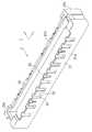
本発明の第1の実施の形態のコネクタ1は、図1の斜視図に示すように、ハウジング2と導電シェル3により構成されている。本実施の形態では、互いに直交するx軸、y軸、及び、z軸を用いて説明する。ハウジング2は、z軸に直交する方向から導電シェル3によって覆われている。コネクタ1は、z軸の正の方向を挿入方向として、z軸の正の方向に位置する図6に示すような相手方コネクタ4に嵌め合わされる。すなわち、コネクタ1において、z軸の正の方向側の部位10が挿入方向先端となり、z軸の負の方向側の部位11が挿入方向後端となる。 The
なお、本実施の形態のコネクタ1は回路基板に固定されているが、ケーブルの端部に形成されたものであってもよい。また、本実施の形態の相手方コネクタ4は回路基板に固定されているが、ケーブルの端部に形成されたものであってもよい。 In addition, although the
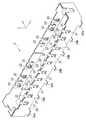
図2の斜視図に示すように、ハウジング2は、ほぼ直方体形状をもち凹部20と外周面21と溝22と鉤溝23とを有し、z軸の負の方向側において回路基板に固定されている。凹部20は、y軸方向よりもx軸方向に長い開口をもち、z軸の負の方向に深く形成され、内部には複数のコンタクトが設けられている。外周面21は、zx平面に平行な第1の外周面21a及び第2の外周面21b、並びに、yz平面に平行な第3の外周面21c及び第4の外周面21dの4面で凹部20を囲んでいる。溝22及び鉤溝23は、第1の外周面21a及び第2の外周面21bに複数設けられている。溝22はz軸に沿って設けられており、z軸の正の方向に開口するとともに、z軸の負の方向においてz軸に交差する底部24を有している。 As shown in the perspective view of FIG. 2, the
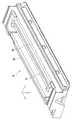
図3の斜視図に示すように、導電シェル3は、板部30とバネ片32と鉤部33と端子部34aと端子部34bとを有する。板部30は、金属板により形成されており図2のハウジング2の外周面21を平行に覆っている。板部30にはx軸方向に並んだ長方形状の複数の貫通孔31が設けられている。貫通孔31は、板部30を、y軸方向に貫通している。なお、貫通孔31は、挿入方向後端側に開口した切り欠きであってもよい。 As shown in the perspective view of FIG. 3, the
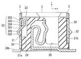
図4は、図1のコネクタのA−A断面図であり、図4に示されるように、バネ片32は、板部30の挿入方向先端側からハウジング2側に延びた後挿入方向後端側に向かって延び、更に、板部30側に傾斜しながら挿入方向後端側に向かって延びながら貫通孔31を通じて板部30のハウジング2と反対側に突出し、更に、板部30側に傾斜しながら挿入方向後端側に向かってわずかにのびた形状をもつ。具体的には、バネ片32は、第1の部位300と第2の部位301と先端部302とを有しており、板部30と一体に形成されている。 4 is a cross-sectional view taken along the line AA of the connector of FIG. 1. As shown in FIG. 4, the
第1の部位300は、板部30の挿入方向先端側から延びており、板部30からハウジング2側に屈曲したのち挿入方向後端側に向かって延びている。すなわち、第1の部位300の一端303は板部30上に設けられており、他端304は板部30よりもハウジング2側に位置している。 The
第2の部位301は、第1の部位300の他端304から挿入方向後端側に向かうとともに板部30側に傾斜しながら延設されており、貫通孔31で板部30と交差してハウジング2の反対側に突出している。すなわち、第2の部位301は、板部30よりもハウジング2側に位置しており第1の部位300の他端304に一致している一端と、板部30を挟んでハウジング2の反対側に位置する他端305とを有している。バネ片32は、第2の部位301の他端305付近でy軸方向に最も突出している。 The
先端部302は、第2の部位301の他端305から挿入方向後端側に向かうとともに貫通孔31側へ屈曲するように延設されている。 The
バネ片32の全長は、貫通孔31のz軸方向の長さよりも大きい。バネ片32は、側壁30と一体に打ち抜かれた板を曲げ加工することにより形成されているため、バネ片32の全長を貫通孔31のz軸方向の長さよりも大きくすることができる。すなわち、貫通孔31内からバネ片を切り起こす場合に比較して、強い弾性力をもち塑性変形しにくいバネ片32を形成することができる。 The overall length of the
ハウジング2の溝22は、バネ片32に対向する位置でバネ片32の可動範囲に設けられている。底部24は、溝22の挿入方向後端側に設けられており、バネ片32の可動範囲以外に溝22を延ばさないことにより、ハウジング2の肉厚をできるだけ厚くしてハウジング2の耐久性を高くすることができる。 The
図5の導電シェル3の側面図に示すように、第2の部位301の他端305付近すなわち接触点付近のx方向の幅は、折り曲げ加工時に貫通孔31から突出させることができるように貫通孔31のx方向の幅よりも狭く形成されている。本実施の形態のバネ片32では、バネ片32の全体にわたってx方向の幅が貫通孔31のx方向の幅よりも狭くなるように形成されているが、バネ片32の塑性変形を防ぐために第1の部位300の一端303付近などのバネ片32の一部の幅が貫通孔31のx方向の幅よりも広く形成されたものであってもよい。 As shown in the side view of the
図3に示す鉤部33は、板部30の挿入方向先端側からハウジング2側に屈曲しながら延び、更に、挿入方向後端側に向けて延設されている。鉤部33の先端は、図2のハウジングの鉤溝32に挿入することができる程度に幅広に形成されている。 The
図3に示す端子部34a及び端子部34bは、板部30の挿入方向後端側に設けられており、板部30を回路基板のグランドに導通させる。 The
導電シェル3は、ハウジング2が回路基板に搭載されている状態で、z軸の負方向に向かってハウジング2に嵌め合わせることができる。導電シェル3とハウジング2との嵌合時に、鉤部33をハウジング2の鉤溝23に挿入することにより導電シェル3を固定する。溝22は、挿入方向先端側に開口をもつため、バネ片32をハウジング2にあてることなく、導電シェル3をハウジング2に嵌め合わせることができる。 The
図6の斜視図に示すように、相手方コネクタ4は、凸部41と相手方導電シェル42とを有する。凸部41は、z軸の負の方向に突出した形状をもちy軸方向よりもx軸方向に幅広く形成されており、y軸方向表面には複数のコンタクトが設けられている。相手方導電シェル42は、zx平面に平行な金属板で形成されており、y軸方向両側から凸部41に対向するように配設されている。 As shown in the perspective view of FIG. 6, the
図7は、図1のコネクタ1に図6に示す相手方コネクタ4を嵌め合わせた状態における、図1に示すA−Aに沿った断面図である。相手方コネクタ4は、z軸の正の方向からコネクタ1を覆うように嵌め合わされる。相手方コネクタ4がコネクタ1に嵌め合わされた状態では、相手方コネクタ4の凸部41が、ハウジング2の凹部20に挿入されており、相手方コネクタ4の相手方コンタクト43がハウジング2のコンタクト25に導通されている。相手方コネクタ4の相手方導電シェル42は、板部30の表面に沿って案内され、y軸方向両側から導電シェル2の板部30を挟むように嵌め合わされる。相手方導電シェル42は、第2の部位301の他端305付近の接触点を押すことにより、バネ片32を溝22側に押す。相手方導電シェル42が斜めに挿入されても、板部30が貫通孔31の周囲を完全に覆っていることから、バネ片32が変形されることが防止される。 7 is a cross-sectional view taken along the line AA shown in FIG. 1 in a state in which the
なお、コネクタ1は、図8の断面図に示すように、第1の部位300の一端303を板部30の挿入方向後端側に設け、接触点を第1の部位300の一端303よりも挿入方向先端側に設けたものであってもよい。 As shown in the cross-sectional view of FIG. 8, the
図9は、第2の実施の形態のコネクタ5の斜視図である。コネクタ5は、ハウジング6と導電シェル7とにより構成されている。ハウジング6は、z軸に直交する方向から導電シェル7によって覆われている。第1の実施の形態の導電性シェル3と比較したときの導電シェル7の特徴は、板部70に切り欠き71とバネ片72とを有している点である。 FIG. 9 is a perspective view of the connector 5 according to the second embodiment. The connector 5 includes a
図10は、図9のB−Bにおける断面図である。図9及び図10に示されるように、切り欠き71は、板部70をy軸方向に貫通しているとともに、板部70の面内において板部70の挿入方向先端部に開放されており、z軸に沿って形成されている。図10に示すようにバネ片72は、切り欠き71の挿入方向後端側からハウジング6側に延びた後挿入方向先端側に延び、更に、挿入方向先端側で板部70側に屈曲した後挿入方向後端側に向かって延び、更に、切り欠き71を通じて板部70のハウジング6と反対側に突出し、更に、板部70側に傾斜しながら挿入方向後端側に向かって延びている。 10 is a cross-sectional view taken along line BB in FIG. As shown in FIGS. 9 and 10, the
具体的には、バネ片72は、第1の部位700と第2の部位701と先端部702とを有している。第1の部位700は、切り欠き71の挿入方向後端側から延びており、板部70からハウジング6側に屈曲したのち挿入方向先端側に向かって延びている。すなわち、第1の部位700の一端703は板部70上に設けられており、他端704は板部70よりもハウジング6側に位置している。第2の部位701は、第1の部位700の他端705から挿入方向後端側に向かうとともに板部70側に傾斜しながら延設されており、切り欠き71で板部70と交差してハウジング6の反対側に突出している。すなわち、第2の部位701は、板部70よりもハウジング6側に位置しており第1の部位700の他端704に一致している一端と、板部70を挟んでハウジング6の反対側に位置する他端705とを有している。バネ片72は、第2の部位701の他端705付近でy軸方向に最も突出している。先端部702は、第2の部位701の他端705から挿入方向後端側に向かうとともに切り欠き71側に屈曲するように延設されている。先端部702は、第1の部位700の一端703付近に位置することとなる。ハウジング6には、バネ片72に対向する位置にバネ片72の可動範囲以上の大きさをもつ溝62が設けられており、溝62の挿入方向後端側には底部64が設けられている。 Specifically, the
なお、コネクタ5は、図11の断面図に示すように、切り欠き71を挿入方向後端側に開口させ、第1の部位700の一端703を板部70の挿入方向先端側に設け、第2の部位701の他端705付近の接触点を第1の部位700の一端703よりも挿入方向後端側に設けたものであってもよい。 As shown in the sectional view of FIG. 11, the connector 5 has a
1 コネクタ
2 ハウジング
3 導電シェル
4 相手方コネクタ
5 コネクタ
6 ハウジング
7 導電シェル
10 部位
11 部位
20 凹部
21 外周面
21a 第1の外周面
21b 第2の外周面
21c 第3の外周面
21d 第4の外周面
22 溝
23 鉤溝
24 底部
25 コンタクト
30 板部
31 貫通孔
32 バネ片
33 鉤部
34a 端子部
34b 端子部
41 凸部
42 相手方導電シェル
43 相手方コンタクト
62 溝
64 底部
70 板部
71 切り欠き
72 バネ片
300 第1の部位
301 第2の部位
302 先端部
303 一端
304 他端
305 他端
700 第1の部位
701 第2の部位
702 先端部
703 一端
704 他端
705 他端
DESCRIPTION OF
Claims (6)
Translated fromJapanese前記板部は、貫通部を有し、
前記貫通部は、孔状に形成されており、
前記導電シェルは、バネ片を更に有し、
前記バネ片は、前記板部の前記所定方向先端側から前記ハウジング側に延びた後に前記貫通部を通じて前記板部の前記ハウジングと反対側に突出した部位を有している
コネクタ。A connector that fits into the mating connector by being inserted into the mating connector along at least a part in a predetermined direction, and includes a contact, a housing that holds the contact, and the direction orthogonal to the predetermined direction. In a connector comprising a conductive shell including a plate portion covering at least a part of the periphery of the housing,
The plate portion has a penetrating portion;
The penetrating part is formed in a hole shape,
The conductive shell further includes a spring piece,
Said spring piece, <br/> connectorthat have a portion that protrudes on the opposite side of the housing of the plate portion through the penetrating part after extending to the housing side fromthe predetermined direction leading end side of the plate portion.
前記板部は、貫通部を有し、
前記貫通部は、孔状に形成されており、
前記導電シェルは、バネ片を更に有し、
前記バネ片は、前記板部の前記所定方向後端側から前記ハウジング側に延びた後に前記貫通部を通じて前記板部の前記ハウジングと反対側に突出した部位を有している
コネクタ。A connector that fits into the mating connector by being inserted into the mating connector along at least a part in a predetermined direction, and includes a contact, a housing that holds the contact, and the direction orthogonal to the predetermined direction. In a connector comprising a conductive shell including a plate portion covering at least a part of the periphery of the housing,
The plate portion has a penetrating portion;
The penetrating part is formed in a hole shape,
The conductive shell further includes a spring piece,
Said spring piece, <br/> connectorthat have a portion that protrudes on the opposite side of the housing of the plate portion through the penetrating portion fromsaid predetermined direction rear end side of the plate portion after extending to the housing side .
請求項1又は請求項2記載のコネクタ。The connector according toclaim 1or 2 , wherein a total length of the spring piece is larger than a length along the predetermined direction of the penetrating portion.
請求項1から請求項3のいずれかに記載のコネクタ。The housing connectoraccording to any one of claims 1 to3 having a groove with an opening in the predetermined direction leading end side provided in a position opposed to the spring piece.
請求項4記載のコネクタ。The connector according to claim4 , wherein the groove has a bottom portion having a surface intersecting the predetermined direction.
請求項1から請求項5のいずれかに記載のコネクタ。The spring piece connectoraccording to any one of claims 1 to5 in which the width in the direction perpendicular to the insertion direction has a predetermined direction greater than the width in the direction orthogonal to the site of the penetrating portion.
Priority Applications (5)
| Application Number | Priority Date | Filing Date | Title |
|---|---|---|---|
| JP2006008202AJP4175657B2 (en) | 2006-01-17 | 2006-01-17 | connector |
| CN2006101721370ACN101005176B (en) | 2006-01-17 | 2006-12-29 | Connector |
| US11/651,877US7431617B2 (en) | 2006-01-17 | 2007-01-10 | Connector |
| KR1020070004659AKR100905576B1 (en) | 2006-01-17 | 2007-01-16 | Connector |
| TW096101537ATWI335106B (en) | 2006-01-17 | 2007-01-16 | Connector |
Applications Claiming Priority (1)
| Application Number | Priority Date | Filing Date | Title |
|---|---|---|---|
| JP2006008202AJP4175657B2 (en) | 2006-01-17 | 2006-01-17 | connector |
Publications (2)
| Publication Number | Publication Date |
|---|---|
| JP2007193949A JP2007193949A (en) | 2007-08-02 |
| JP4175657B2true JP4175657B2 (en) | 2008-11-05 |
Family
ID=38263816
Family Applications (1)
| Application Number | Title | Priority Date | Filing Date |
|---|---|---|---|
| JP2006008202AExpired - Fee RelatedJP4175657B2 (en) | 2006-01-17 | 2006-01-17 | connector |
Country Status (5)
| Country | Link |
|---|---|
| US (1) | US7431617B2 (en) |
| JP (1) | JP4175657B2 (en) |
| KR (1) | KR100905576B1 (en) |
| CN (1) | CN101005176B (en) |
| TW (1) | TWI335106B (en) |
Families Citing this family (12)
| Publication number | Priority date | Publication date | Assignee | Title |
|---|---|---|---|---|
| JP5110271B2 (en)* | 2007-08-22 | 2012-12-26 | 第一精工株式会社 | Connector device |
| JP4493710B2 (en) | 2008-09-19 | 2010-06-30 | 株式会社アイペックス | Electrical connector |
| EP2351162A1 (en)* | 2008-10-22 | 2011-08-03 | Fci | Shielded connector |
| JP4704477B2 (en)* | 2009-02-19 | 2011-06-15 | 日本航空電子工業株式会社 | Connector assembly |
| JP5594053B2 (en)* | 2010-10-22 | 2014-09-24 | 第一精工株式会社 | Electrical connector and assembly thereof |
| JP5818016B2 (en)* | 2012-05-17 | 2015-11-18 | 第一精工株式会社 | Connector device |
| US9065228B2 (en)* | 2013-11-21 | 2015-06-23 | Japan Aviation Electronics Industry, Limited | Connector |
| JP6167997B2 (en)* | 2014-06-05 | 2017-07-26 | 株式会社村田製作所 | Connector set and connector |
| JP7502167B2 (en)* | 2020-12-10 | 2024-06-18 | 日本航空電子工業株式会社 | Board to Board Connectors, Connector Assemblies |
| TWI782354B (en)* | 2020-04-24 | 2022-11-01 | 大陸商東莞立訊技術有限公司 | Board end connector and connector assembly |
| CN113675666A (en)* | 2020-05-13 | 2021-11-19 | 日本航空电子工业株式会社 | Connector |
| TWD212168S (en) | 2020-09-24 | 2021-06-11 | 大陸商東莞立訊技術有限公司 | Part of connector housing |
Family Cites Families (19)
| Publication number | Priority date | Publication date | Assignee | Title |
|---|---|---|---|---|
| US4346952A (en) | 1980-06-16 | 1982-08-31 | Amp Incorporated | Connector for a ceramic substrate |
| EP0205876A1 (en)* | 1985-06-19 | 1986-12-30 | Siemens Aktiengesellschaft | Multipole pluggable device having a locating strip with a shielding device |
| JP3203501B2 (en)* | 1995-11-20 | 2001-08-27 | モレックス インコーポレーテッド | Edge connectors for printed circuit boards |
| JPH0298075A (en)* | 1988-10-04 | 1990-04-10 | Hirose Electric Co Ltd | electrical connectors |
| JPH0313681A (en) | 1989-06-10 | 1991-01-22 | Eidai Co Ltd | building materials |
| JPH0729586Y2 (en)* | 1989-06-27 | 1995-07-05 | ホシデン株式会社 | connector |
| US5637014A (en)* | 1994-01-31 | 1997-06-10 | Mitsumi Electric Co., Ltd. | Electrical connector |
| JP3361645B2 (en)* | 1995-03-03 | 2003-01-07 | 富士通株式会社 | Jack connector and connector including jack connector |
| US5496195A (en)* | 1995-03-13 | 1996-03-05 | The Whitaker Corporation | High performance shielded connector |
| JPH10289760A (en)* | 1997-04-11 | 1998-10-27 | Molex Inc | Metal shell connection means |
| JP3323444B2 (en) | 1998-07-22 | 2002-09-09 | 株式会社アドバンスト・ディスプレイ | Liquid crystal display |
| JP4574883B2 (en)* | 2001-03-26 | 2010-11-04 | モレックス インコーポレイテド | Connector shield connection device |
| US6478623B1 (en) | 2001-12-11 | 2002-11-12 | Hon Hai Precision Ind. Co., Ltd. | Header connector with shell |
| US6485328B1 (en)* | 2001-12-19 | 2002-11-26 | Hon Hai Precision Ind. Co., Ltd. | Header connector with shell |
| CN2600951Y (en)* | 2003-01-24 | 2004-01-21 | 富士康(昆山)电脑接插件有限公司 | Electric connector assembly |
| JP3516163B1 (en) | 2003-04-24 | 2004-04-05 | 日本航空電子工業株式会社 | connector |
| TWM250431U (en)* | 2003-08-08 | 2004-11-11 | Hon Hai Prec Ind Co Ltd | Electrical connector |
| CN2665984Y (en)* | 2003-08-27 | 2004-12-22 | 富士康(昆山)电脑接插件有限公司 | Electric connector |
| JP3890060B2 (en)* | 2004-09-16 | 2007-03-07 | ヒロセ電機株式会社 | Electrical connector |
- 2006
- 2006-01-17JPJP2006008202Apatent/JP4175657B2/ennot_activeExpired - Fee Related
- 2006-12-29CNCN2006101721370Apatent/CN101005176B/ennot_activeExpired - Fee Related
- 2007
- 2007-01-10USUS11/651,877patent/US7431617B2/ennot_activeExpired - Fee Related
- 2007-01-16KRKR1020070004659Apatent/KR100905576B1/ennot_activeExpired - Fee Related
- 2007-01-16TWTW096101537Apatent/TWI335106B/ennot_activeIP Right Cessation
Also Published As
| Publication number | Publication date |
|---|---|
| TWI335106B (en) | 2010-12-21 |
| KR20070076502A (en) | 2007-07-24 |
| JP2007193949A (en) | 2007-08-02 |
| TW200746548A (en) | 2007-12-16 |
| CN101005176A (en) | 2007-07-25 |
| US7431617B2 (en) | 2008-10-07 |
| KR100905576B1 (en) | 2009-07-02 |
| CN101005176B (en) | 2010-05-19 |
| US20070167078A1 (en) | 2007-07-19 |
Similar Documents
| Publication | Publication Date | Title |
|---|---|---|
| JP4175657B2 (en) | connector | |
| JP4809816B2 (en) | connector | |
| CN101183758B (en) | Electrical connector | |
| JP4368897B2 (en) | connector | |
| JP4749919B2 (en) | Spring loaded female terminal | |
| US7806739B2 (en) | Battery connector with time-delay function | |
| US20070141891A1 (en) | Electrical connector | |
| US8942007B2 (en) | Electrical component | |
| JP2009016138A (en) | Electrical connector | |
| EP2472678A2 (en) | Connector member comprising a retainer | |
| JP2009517802A (en) | Electrical connector | |
| TWI865565B (en) | Safe, robust, compact connector and method for mating connector | |
| JP2005294217A (en) | Pressure contact type contact and electrical connector using the same | |
| JP2008112682A (en) | Card edge type connector | |
| JP6815029B2 (en) | Contact, connector member, connector and connected member | |
| JP4353537B2 (en) | connector | |
| JP2000311740A (en) | Electrical contacts | |
| KR101175170B1 (en) | Socket contact | |
| JP5388350B2 (en) | Electrical connection terminal and connector using the same | |
| JP6687260B1 (en) | connector | |
| US8851922B2 (en) | Electrical connector device and connector used in the electrical connector device | |
| JP6723567B2 (en) | connector | |
| JP2007042398A (en) | Receptacle, plug and connector | |
| CN201142395Y (en) | Conductive terminals and electrical connectors | |
| JP3745977B2 (en) | Wire connection device |
Legal Events
| Date | Code | Title | Description |
|---|---|---|---|
| A977 | Report on retrieval | Free format text:JAPANESE INTERMEDIATE CODE: A971007 Effective date:20080417 | |
| A131 | Notification of reasons for refusal | Free format text:JAPANESE INTERMEDIATE CODE: A131 Effective date:20080430 | |
| A521 | Written amendment | Free format text:JAPANESE INTERMEDIATE CODE: A523 Effective date:20080625 | |
| TRDD | Decision of grant or rejection written | ||
| A01 | Written decision to grant a patent or to grant a registration (utility model) | Free format text:JAPANESE INTERMEDIATE CODE: A01 Effective date:20080814 | |
| A01 | Written decision to grant a patent or to grant a registration (utility model) | Free format text:JAPANESE INTERMEDIATE CODE: A01 | |
| A61 | First payment of annual fees (during grant procedure) | Free format text:JAPANESE INTERMEDIATE CODE: A61 Effective date:20080818 | |
| FPAY | Renewal fee payment (event date is renewal date of database) | Free format text:PAYMENT UNTIL: 20110829 Year of fee payment:3 | |
| R150 | Certificate of patent or registration of utility model | Free format text:JAPANESE INTERMEDIATE CODE: R150 | |
| FPAY | Renewal fee payment (event date is renewal date of database) | Free format text:PAYMENT UNTIL: 20120829 Year of fee payment:4 | |
| FPAY | Renewal fee payment (event date is renewal date of database) | Free format text:PAYMENT UNTIL: 20120829 Year of fee payment:4 | |
| FPAY | Renewal fee payment (event date is renewal date of database) | Free format text:PAYMENT UNTIL: 20120829 Year of fee payment:4 | |
| FPAY | Renewal fee payment (event date is renewal date of database) | Free format text:PAYMENT UNTIL: 20120829 Year of fee payment:4 | |
| FPAY | Renewal fee payment (event date is renewal date of database) | Free format text:PAYMENT UNTIL: 20130829 Year of fee payment:5 | |
| FPAY | Renewal fee payment (event date is renewal date of database) | Free format text:PAYMENT UNTIL: 20130829 Year of fee payment:5 | |
| R250 | Receipt of annual fees | Free format text:JAPANESE INTERMEDIATE CODE: R250 | |
| R250 | Receipt of annual fees | Free format text:JAPANESE INTERMEDIATE CODE: R250 | |
| R250 | Receipt of annual fees | Free format text:JAPANESE INTERMEDIATE CODE: R250 | |
| LAPS | Cancellation because of no payment of annual fees |