JP4175370B2 - Hybrid vehicle and control method thereof - Google Patents
Hybrid vehicle and control method thereofDownload PDFInfo
- Publication number
- JP4175370B2 JP4175370B2JP2006006236AJP2006006236AJP4175370B2JP 4175370 B2JP4175370 B2JP 4175370B2JP 2006006236 AJP2006006236 AJP 2006006236AJP 2006006236 AJP2006006236 AJP 2006006236AJP 4175370 B2JP4175370 B2JP 4175370B2
- Authority
- JP
- Japan
- Prior art keywords
- power
- internal combustion
- output
- combustion engine
- engine
- Prior art date
- Legal status (The legal status is an assumption and is not a legal conclusion. Google has not performed a legal analysis and makes no representation as to the accuracy of the status listed.)
- Active
Links
Images


Classifications
- B—PERFORMING OPERATIONS; TRANSPORTING
- B60—VEHICLES IN GENERAL
- B60W—CONJOINT CONTROL OF VEHICLE SUB-UNITS OF DIFFERENT TYPE OR DIFFERENT FUNCTION; CONTROL SYSTEMS SPECIALLY ADAPTED FOR HYBRID VEHICLES; ROAD VEHICLE DRIVE CONTROL SYSTEMS FOR PURPOSES NOT RELATED TO THE CONTROL OF A PARTICULAR SUB-UNIT
- B60W10/00—Conjoint control of vehicle sub-units of different type or different function
- B60W10/04—Conjoint control of vehicle sub-units of different type or different function including control of propulsion units
- B60W10/06—Conjoint control of vehicle sub-units of different type or different function including control of propulsion units including control of combustion engines
- B—PERFORMING OPERATIONS; TRANSPORTING
- B60—VEHICLES IN GENERAL
- B60L—PROPULSION OF ELECTRICALLY-PROPELLED VEHICLES; SUPPLYING ELECTRIC POWER FOR AUXILIARY EQUIPMENT OF ELECTRICALLY-PROPELLED VEHICLES; ELECTRODYNAMIC BRAKE SYSTEMS FOR VEHICLES IN GENERAL; MAGNETIC SUSPENSION OR LEVITATION FOR VEHICLES; MONITORING OPERATING VARIABLES OF ELECTRICALLY-PROPELLED VEHICLES; ELECTRIC SAFETY DEVICES FOR ELECTRICALLY-PROPELLED VEHICLES
- B60L58/00—Methods or circuit arrangements for monitoring or controlling batteries or fuel cells, specially adapted for electric vehicles
- B60L58/10—Methods or circuit arrangements for monitoring or controlling batteries or fuel cells, specially adapted for electric vehicles for monitoring or controlling batteries
- B60L58/12—Methods or circuit arrangements for monitoring or controlling batteries or fuel cells, specially adapted for electric vehicles for monitoring or controlling batteries responding to state of charge [SoC]
- B60L58/15—Preventing overcharging
- B—PERFORMING OPERATIONS; TRANSPORTING
- B60—VEHICLES IN GENERAL
- B60K—ARRANGEMENT OR MOUNTING OF PROPULSION UNITS OR OF TRANSMISSIONS IN VEHICLES; ARRANGEMENT OR MOUNTING OF PLURAL DIVERSE PRIME-MOVERS IN VEHICLES; AUXILIARY DRIVES FOR VEHICLES; INSTRUMENTATION OR DASHBOARDS FOR VEHICLES; ARRANGEMENTS IN CONNECTION WITH COOLING, AIR INTAKE, GAS EXHAUST OR FUEL SUPPLY OF PROPULSION UNITS IN VEHICLES
- B60K6/00—Arrangement or mounting of plural diverse prime-movers for mutual or common propulsion, e.g. hybrid propulsion systems comprising electric motors and internal combustion engines
- B60K6/20—Arrangement or mounting of plural diverse prime-movers for mutual or common propulsion, e.g. hybrid propulsion systems comprising electric motors and internal combustion engines the prime-movers consisting of electric motors and internal combustion engines, e.g. HEVs
- B60K6/42—Arrangement or mounting of plural diverse prime-movers for mutual or common propulsion, e.g. hybrid propulsion systems comprising electric motors and internal combustion engines the prime-movers consisting of electric motors and internal combustion engines, e.g. HEVs characterised by the architecture of the hybrid electric vehicle
- B60K6/44—Series-parallel type
- B60K6/445—Differential gearing distribution type
- B—PERFORMING OPERATIONS; TRANSPORTING
- B60—VEHICLES IN GENERAL
- B60K—ARRANGEMENT OR MOUNTING OF PROPULSION UNITS OR OF TRANSMISSIONS IN VEHICLES; ARRANGEMENT OR MOUNTING OF PLURAL DIVERSE PRIME-MOVERS IN VEHICLES; AUXILIARY DRIVES FOR VEHICLES; INSTRUMENTATION OR DASHBOARDS FOR VEHICLES; ARRANGEMENTS IN CONNECTION WITH COOLING, AIR INTAKE, GAS EXHAUST OR FUEL SUPPLY OF PROPULSION UNITS IN VEHICLES
- B60K6/00—Arrangement or mounting of plural diverse prime-movers for mutual or common propulsion, e.g. hybrid propulsion systems comprising electric motors and internal combustion engines
- B60K6/20—Arrangement or mounting of plural diverse prime-movers for mutual or common propulsion, e.g. hybrid propulsion systems comprising electric motors and internal combustion engines the prime-movers consisting of electric motors and internal combustion engines, e.g. HEVs
- B60K6/42—Arrangement or mounting of plural diverse prime-movers for mutual or common propulsion, e.g. hybrid propulsion systems comprising electric motors and internal combustion engines the prime-movers consisting of electric motors and internal combustion engines, e.g. HEVs characterised by the architecture of the hybrid electric vehicle
- B60K6/44—Series-parallel type
- B60K6/448—Electrical distribution type
- B—PERFORMING OPERATIONS; TRANSPORTING
- B60—VEHICLES IN GENERAL
- B60L—PROPULSION OF ELECTRICALLY-PROPELLED VEHICLES; SUPPLYING ELECTRIC POWER FOR AUXILIARY EQUIPMENT OF ELECTRICALLY-PROPELLED VEHICLES; ELECTRODYNAMIC BRAKE SYSTEMS FOR VEHICLES IN GENERAL; MAGNETIC SUSPENSION OR LEVITATION FOR VEHICLES; MONITORING OPERATING VARIABLES OF ELECTRICALLY-PROPELLED VEHICLES; ELECTRIC SAFETY DEVICES FOR ELECTRICALLY-PROPELLED VEHICLES
- B60L15/00—Methods, circuits, or devices for controlling the traction-motor speed of electrically-propelled vehicles
- B60L15/20—Methods, circuits, or devices for controlling the traction-motor speed of electrically-propelled vehicles for control of the vehicle or its driving motor to achieve a desired performance, e.g. speed, torque, programmed variation of speed
- B60L15/2009—Methods, circuits, or devices for controlling the traction-motor speed of electrically-propelled vehicles for control of the vehicle or its driving motor to achieve a desired performance, e.g. speed, torque, programmed variation of speed for braking
- B—PERFORMING OPERATIONS; TRANSPORTING
- B60—VEHICLES IN GENERAL
- B60L—PROPULSION OF ELECTRICALLY-PROPELLED VEHICLES; SUPPLYING ELECTRIC POWER FOR AUXILIARY EQUIPMENT OF ELECTRICALLY-PROPELLED VEHICLES; ELECTRODYNAMIC BRAKE SYSTEMS FOR VEHICLES IN GENERAL; MAGNETIC SUSPENSION OR LEVITATION FOR VEHICLES; MONITORING OPERATING VARIABLES OF ELECTRICALLY-PROPELLED VEHICLES; ELECTRIC SAFETY DEVICES FOR ELECTRICALLY-PROPELLED VEHICLES
- B60L15/00—Methods, circuits, or devices for controlling the traction-motor speed of electrically-propelled vehicles
- B60L15/20—Methods, circuits, or devices for controlling the traction-motor speed of electrically-propelled vehicles for control of the vehicle or its driving motor to achieve a desired performance, e.g. speed, torque, programmed variation of speed
- B60L15/2045—Methods, circuits, or devices for controlling the traction-motor speed of electrically-propelled vehicles for control of the vehicle or its driving motor to achieve a desired performance, e.g. speed, torque, programmed variation of speed for optimising the use of energy
- B—PERFORMING OPERATIONS; TRANSPORTING
- B60—VEHICLES IN GENERAL
- B60L—PROPULSION OF ELECTRICALLY-PROPELLED VEHICLES; SUPPLYING ELECTRIC POWER FOR AUXILIARY EQUIPMENT OF ELECTRICALLY-PROPELLED VEHICLES; ELECTRODYNAMIC BRAKE SYSTEMS FOR VEHICLES IN GENERAL; MAGNETIC SUSPENSION OR LEVITATION FOR VEHICLES; MONITORING OPERATING VARIABLES OF ELECTRICALLY-PROPELLED VEHICLES; ELECTRIC SAFETY DEVICES FOR ELECTRICALLY-PROPELLED VEHICLES
- B60L50/00—Electric propulsion with power supplied within the vehicle
- B60L50/10—Electric propulsion with power supplied within the vehicle using propulsion power supplied by engine-driven generators, e.g. generators driven by combustion engines
- B60L50/16—Electric propulsion with power supplied within the vehicle using propulsion power supplied by engine-driven generators, e.g. generators driven by combustion engines with provision for separate direct mechanical propulsion
- B—PERFORMING OPERATIONS; TRANSPORTING
- B60—VEHICLES IN GENERAL
- B60L—PROPULSION OF ELECTRICALLY-PROPELLED VEHICLES; SUPPLYING ELECTRIC POWER FOR AUXILIARY EQUIPMENT OF ELECTRICALLY-PROPELLED VEHICLES; ELECTRODYNAMIC BRAKE SYSTEMS FOR VEHICLES IN GENERAL; MAGNETIC SUSPENSION OR LEVITATION FOR VEHICLES; MONITORING OPERATING VARIABLES OF ELECTRICALLY-PROPELLED VEHICLES; ELECTRIC SAFETY DEVICES FOR ELECTRICALLY-PROPELLED VEHICLES
- B60L50/00—Electric propulsion with power supplied within the vehicle
- B60L50/50—Electric propulsion with power supplied within the vehicle using propulsion power supplied by batteries or fuel cells
- B60L50/60—Electric propulsion with power supplied within the vehicle using propulsion power supplied by batteries or fuel cells using power supplied by batteries
- B60L50/61—Electric propulsion with power supplied within the vehicle using propulsion power supplied by batteries or fuel cells using power supplied by batteries by batteries charged by engine-driven generators, e.g. series hybrid electric vehicles
- B—PERFORMING OPERATIONS; TRANSPORTING
- B60—VEHICLES IN GENERAL
- B60L—PROPULSION OF ELECTRICALLY-PROPELLED VEHICLES; SUPPLYING ELECTRIC POWER FOR AUXILIARY EQUIPMENT OF ELECTRICALLY-PROPELLED VEHICLES; ELECTRODYNAMIC BRAKE SYSTEMS FOR VEHICLES IN GENERAL; MAGNETIC SUSPENSION OR LEVITATION FOR VEHICLES; MONITORING OPERATING VARIABLES OF ELECTRICALLY-PROPELLED VEHICLES; ELECTRIC SAFETY DEVICES FOR ELECTRICALLY-PROPELLED VEHICLES
- B60L58/00—Methods or circuit arrangements for monitoring or controlling batteries or fuel cells, specially adapted for electric vehicles
- B60L58/10—Methods or circuit arrangements for monitoring or controlling batteries or fuel cells, specially adapted for electric vehicles for monitoring or controlling batteries
- B60L58/24—Methods or circuit arrangements for monitoring or controlling batteries or fuel cells, specially adapted for electric vehicles for monitoring or controlling batteries for controlling the temperature of batteries
- B60L58/25—Methods or circuit arrangements for monitoring or controlling batteries or fuel cells, specially adapted for electric vehicles for monitoring or controlling batteries for controlling the temperature of batteries by controlling the electric load
- B—PERFORMING OPERATIONS; TRANSPORTING
- B60—VEHICLES IN GENERAL
- B60L—PROPULSION OF ELECTRICALLY-PROPELLED VEHICLES; SUPPLYING ELECTRIC POWER FOR AUXILIARY EQUIPMENT OF ELECTRICALLY-PROPELLED VEHICLES; ELECTRODYNAMIC BRAKE SYSTEMS FOR VEHICLES IN GENERAL; MAGNETIC SUSPENSION OR LEVITATION FOR VEHICLES; MONITORING OPERATING VARIABLES OF ELECTRICALLY-PROPELLED VEHICLES; ELECTRIC SAFETY DEVICES FOR ELECTRICALLY-PROPELLED VEHICLES
- B60L7/00—Electrodynamic brake systems for vehicles in general
- B60L7/10—Dynamic electric regenerative braking
- B60L7/14—Dynamic electric regenerative braking for vehicles propelled by AC motors
- B—PERFORMING OPERATIONS; TRANSPORTING
- B60—VEHICLES IN GENERAL
- B60L—PROPULSION OF ELECTRICALLY-PROPELLED VEHICLES; SUPPLYING ELECTRIC POWER FOR AUXILIARY EQUIPMENT OF ELECTRICALLY-PROPELLED VEHICLES; ELECTRODYNAMIC BRAKE SYSTEMS FOR VEHICLES IN GENERAL; MAGNETIC SUSPENSION OR LEVITATION FOR VEHICLES; MONITORING OPERATING VARIABLES OF ELECTRICALLY-PROPELLED VEHICLES; ELECTRIC SAFETY DEVICES FOR ELECTRICALLY-PROPELLED VEHICLES
- B60L7/00—Electrodynamic brake systems for vehicles in general
- B60L7/24—Electrodynamic brake systems for vehicles in general with additional mechanical or electromagnetic braking
- B60L7/26—Controlling the braking effect
- B—PERFORMING OPERATIONS; TRANSPORTING
- B60—VEHICLES IN GENERAL
- B60W—CONJOINT CONTROL OF VEHICLE SUB-UNITS OF DIFFERENT TYPE OR DIFFERENT FUNCTION; CONTROL SYSTEMS SPECIALLY ADAPTED FOR HYBRID VEHICLES; ROAD VEHICLE DRIVE CONTROL SYSTEMS FOR PURPOSES NOT RELATED TO THE CONTROL OF A PARTICULAR SUB-UNIT
- B60W10/00—Conjoint control of vehicle sub-units of different type or different function
- B60W10/04—Conjoint control of vehicle sub-units of different type or different function including control of propulsion units
- B60W10/08—Conjoint control of vehicle sub-units of different type or different function including control of propulsion units including control of electric propulsion units, e.g. motors or generators
- B—PERFORMING OPERATIONS; TRANSPORTING
- B60—VEHICLES IN GENERAL
- B60W—CONJOINT CONTROL OF VEHICLE SUB-UNITS OF DIFFERENT TYPE OR DIFFERENT FUNCTION; CONTROL SYSTEMS SPECIALLY ADAPTED FOR HYBRID VEHICLES; ROAD VEHICLE DRIVE CONTROL SYSTEMS FOR PURPOSES NOT RELATED TO THE CONTROL OF A PARTICULAR SUB-UNIT
- B60W10/00—Conjoint control of vehicle sub-units of different type or different function
- B60W10/24—Conjoint control of vehicle sub-units of different type or different function including control of energy storage means
- B60W10/26—Conjoint control of vehicle sub-units of different type or different function including control of energy storage means for electrical energy, e.g. batteries or capacitors
- B—PERFORMING OPERATIONS; TRANSPORTING
- B60—VEHICLES IN GENERAL
- B60W—CONJOINT CONTROL OF VEHICLE SUB-UNITS OF DIFFERENT TYPE OR DIFFERENT FUNCTION; CONTROL SYSTEMS SPECIALLY ADAPTED FOR HYBRID VEHICLES; ROAD VEHICLE DRIVE CONTROL SYSTEMS FOR PURPOSES NOT RELATED TO THE CONTROL OF A PARTICULAR SUB-UNIT
- B60W20/00—Control systems specially adapted for hybrid vehicles
- B60W20/10—Controlling the power contribution of each of the prime movers to meet required power demand
- B60W20/15—Control strategies specially adapted for achieving a particular effect
- F—MECHANICAL ENGINEERING; LIGHTING; HEATING; WEAPONS; BLASTING
- F01—MACHINES OR ENGINES IN GENERAL; ENGINE PLANTS IN GENERAL; STEAM ENGINES
- F01N—GAS-FLOW SILENCERS OR EXHAUST APPARATUS FOR MACHINES OR ENGINES IN GENERAL; GAS-FLOW SILENCERS OR EXHAUST APPARATUS FOR INTERNAL-COMBUSTION ENGINES
- F01N3/00—Exhaust or silencing apparatus having means for purifying, rendering innocuous, or otherwise treating exhaust
- F01N3/02—Exhaust or silencing apparatus having means for purifying, rendering innocuous, or otherwise treating exhaust for cooling, or for removing solid constituents of, exhaust
- F01N3/04—Exhaust or silencing apparatus having means for purifying, rendering innocuous, or otherwise treating exhaust for cooling, or for removing solid constituents of, exhaust using liquids
- F—MECHANICAL ENGINEERING; LIGHTING; HEATING; WEAPONS; BLASTING
- F02—COMBUSTION ENGINES; HOT-GAS OR COMBUSTION-PRODUCT ENGINE PLANTS
- F02D—CONTROLLING COMBUSTION ENGINES
- F02D29/00—Controlling engines, such controlling being peculiar to the devices driven thereby, the devices being other than parts or accessories essential to engine operation, e.g. controlling of engines by signals external thereto
- F02D29/02—Controlling engines, such controlling being peculiar to the devices driven thereby, the devices being other than parts or accessories essential to engine operation, e.g. controlling of engines by signals external thereto peculiar to engines driving vehicles; peculiar to engines driving variable pitch propellers
- B—PERFORMING OPERATIONS; TRANSPORTING
- B60—VEHICLES IN GENERAL
- B60L—PROPULSION OF ELECTRICALLY-PROPELLED VEHICLES; SUPPLYING ELECTRIC POWER FOR AUXILIARY EQUIPMENT OF ELECTRICALLY-PROPELLED VEHICLES; ELECTRODYNAMIC BRAKE SYSTEMS FOR VEHICLES IN GENERAL; MAGNETIC SUSPENSION OR LEVITATION FOR VEHICLES; MONITORING OPERATING VARIABLES OF ELECTRICALLY-PROPELLED VEHICLES; ELECTRIC SAFETY DEVICES FOR ELECTRICALLY-PROPELLED VEHICLES
- B60L2240/00—Control parameters of input or output; Target parameters
- B60L2240/40—Drive Train control parameters
- B60L2240/42—Drive Train control parameters related to electric machines
- B60L2240/421—Speed
- B—PERFORMING OPERATIONS; TRANSPORTING
- B60—VEHICLES IN GENERAL
- B60L—PROPULSION OF ELECTRICALLY-PROPELLED VEHICLES; SUPPLYING ELECTRIC POWER FOR AUXILIARY EQUIPMENT OF ELECTRICALLY-PROPELLED VEHICLES; ELECTRODYNAMIC BRAKE SYSTEMS FOR VEHICLES IN GENERAL; MAGNETIC SUSPENSION OR LEVITATION FOR VEHICLES; MONITORING OPERATING VARIABLES OF ELECTRICALLY-PROPELLED VEHICLES; ELECTRIC SAFETY DEVICES FOR ELECTRICALLY-PROPELLED VEHICLES
- B60L2240/00—Control parameters of input or output; Target parameters
- B60L2240/40—Drive Train control parameters
- B60L2240/42—Drive Train control parameters related to electric machines
- B60L2240/423—Torque
- B—PERFORMING OPERATIONS; TRANSPORTING
- B60—VEHICLES IN GENERAL
- B60L—PROPULSION OF ELECTRICALLY-PROPELLED VEHICLES; SUPPLYING ELECTRIC POWER FOR AUXILIARY EQUIPMENT OF ELECTRICALLY-PROPELLED VEHICLES; ELECTRODYNAMIC BRAKE SYSTEMS FOR VEHICLES IN GENERAL; MAGNETIC SUSPENSION OR LEVITATION FOR VEHICLES; MONITORING OPERATING VARIABLES OF ELECTRICALLY-PROPELLED VEHICLES; ELECTRIC SAFETY DEVICES FOR ELECTRICALLY-PROPELLED VEHICLES
- B60L2240/00—Control parameters of input or output; Target parameters
- B60L2240/40—Drive Train control parameters
- B60L2240/44—Drive Train control parameters related to combustion engines
- B60L2240/441—Speed
- B—PERFORMING OPERATIONS; TRANSPORTING
- B60—VEHICLES IN GENERAL
- B60L—PROPULSION OF ELECTRICALLY-PROPELLED VEHICLES; SUPPLYING ELECTRIC POWER FOR AUXILIARY EQUIPMENT OF ELECTRICALLY-PROPELLED VEHICLES; ELECTRODYNAMIC BRAKE SYSTEMS FOR VEHICLES IN GENERAL; MAGNETIC SUSPENSION OR LEVITATION FOR VEHICLES; MONITORING OPERATING VARIABLES OF ELECTRICALLY-PROPELLED VEHICLES; ELECTRIC SAFETY DEVICES FOR ELECTRICALLY-PROPELLED VEHICLES
- B60L2240/00—Control parameters of input or output; Target parameters
- B60L2240/40—Drive Train control parameters
- B60L2240/44—Drive Train control parameters related to combustion engines
- B60L2240/443—Torque
- B—PERFORMING OPERATIONS; TRANSPORTING
- B60—VEHICLES IN GENERAL
- B60L—PROPULSION OF ELECTRICALLY-PROPELLED VEHICLES; SUPPLYING ELECTRIC POWER FOR AUXILIARY EQUIPMENT OF ELECTRICALLY-PROPELLED VEHICLES; ELECTRODYNAMIC BRAKE SYSTEMS FOR VEHICLES IN GENERAL; MAGNETIC SUSPENSION OR LEVITATION FOR VEHICLES; MONITORING OPERATING VARIABLES OF ELECTRICALLY-PROPELLED VEHICLES; ELECTRIC SAFETY DEVICES FOR ELECTRICALLY-PROPELLED VEHICLES
- B60L2240/00—Control parameters of input or output; Target parameters
- B60L2240/40—Drive Train control parameters
- B60L2240/54—Drive Train control parameters related to batteries
- B60L2240/545—Temperature
- B—PERFORMING OPERATIONS; TRANSPORTING
- B60—VEHICLES IN GENERAL
- B60L—PROPULSION OF ELECTRICALLY-PROPELLED VEHICLES; SUPPLYING ELECTRIC POWER FOR AUXILIARY EQUIPMENT OF ELECTRICALLY-PROPELLED VEHICLES; ELECTRODYNAMIC BRAKE SYSTEMS FOR VEHICLES IN GENERAL; MAGNETIC SUSPENSION OR LEVITATION FOR VEHICLES; MONITORING OPERATING VARIABLES OF ELECTRICALLY-PROPELLED VEHICLES; ELECTRIC SAFETY DEVICES FOR ELECTRICALLY-PROPELLED VEHICLES
- B60L2240/00—Control parameters of input or output; Target parameters
- B60L2240/80—Time limits
- B—PERFORMING OPERATIONS; TRANSPORTING
- B60—VEHICLES IN GENERAL
- B60L—PROPULSION OF ELECTRICALLY-PROPELLED VEHICLES; SUPPLYING ELECTRIC POWER FOR AUXILIARY EQUIPMENT OF ELECTRICALLY-PROPELLED VEHICLES; ELECTRODYNAMIC BRAKE SYSTEMS FOR VEHICLES IN GENERAL; MAGNETIC SUSPENSION OR LEVITATION FOR VEHICLES; MONITORING OPERATING VARIABLES OF ELECTRICALLY-PROPELLED VEHICLES; ELECTRIC SAFETY DEVICES FOR ELECTRICALLY-PROPELLED VEHICLES
- B60L2250/00—Driver interactions
- B60L2250/26—Driver interactions by pedal actuation
- B—PERFORMING OPERATIONS; TRANSPORTING
- B60—VEHICLES IN GENERAL
- B60L—PROPULSION OF ELECTRICALLY-PROPELLED VEHICLES; SUPPLYING ELECTRIC POWER FOR AUXILIARY EQUIPMENT OF ELECTRICALLY-PROPELLED VEHICLES; ELECTRODYNAMIC BRAKE SYSTEMS FOR VEHICLES IN GENERAL; MAGNETIC SUSPENSION OR LEVITATION FOR VEHICLES; MONITORING OPERATING VARIABLES OF ELECTRICALLY-PROPELLED VEHICLES; ELECTRIC SAFETY DEVICES FOR ELECTRICALLY-PROPELLED VEHICLES
- B60L2260/00—Operating Modes
- B60L2260/10—Temporary overload
- B60L2260/12—Temporary overload of combustion engines
- B—PERFORMING OPERATIONS; TRANSPORTING
- B60—VEHICLES IN GENERAL
- B60L—PROPULSION OF ELECTRICALLY-PROPELLED VEHICLES; SUPPLYING ELECTRIC POWER FOR AUXILIARY EQUIPMENT OF ELECTRICALLY-PROPELLED VEHICLES; ELECTRODYNAMIC BRAKE SYSTEMS FOR VEHICLES IN GENERAL; MAGNETIC SUSPENSION OR LEVITATION FOR VEHICLES; MONITORING OPERATING VARIABLES OF ELECTRICALLY-PROPELLED VEHICLES; ELECTRIC SAFETY DEVICES FOR ELECTRICALLY-PROPELLED VEHICLES
- B60L2260/00—Operating Modes
- B60L2260/20—Drive modes; Transition between modes
- B60L2260/24—Coasting mode
- B—PERFORMING OPERATIONS; TRANSPORTING
- B60—VEHICLES IN GENERAL
- B60W—CONJOINT CONTROL OF VEHICLE SUB-UNITS OF DIFFERENT TYPE OR DIFFERENT FUNCTION; CONTROL SYSTEMS SPECIALLY ADAPTED FOR HYBRID VEHICLES; ROAD VEHICLE DRIVE CONTROL SYSTEMS FOR PURPOSES NOT RELATED TO THE CONTROL OF A PARTICULAR SUB-UNIT
- B60W2510/00—Input parameters relating to a particular sub-units
- B60W2510/10—Change speed gearings
- B—PERFORMING OPERATIONS; TRANSPORTING
- B60—VEHICLES IN GENERAL
- B60W—CONJOINT CONTROL OF VEHICLE SUB-UNITS OF DIFFERENT TYPE OR DIFFERENT FUNCTION; CONTROL SYSTEMS SPECIALLY ADAPTED FOR HYBRID VEHICLES; ROAD VEHICLE DRIVE CONTROL SYSTEMS FOR PURPOSES NOT RELATED TO THE CONTROL OF A PARTICULAR SUB-UNIT
- B60W2510/00—Input parameters relating to a particular sub-units
- B60W2510/24—Energy storage means
- B60W2510/242—Energy storage means for electrical energy
- B60W2510/244—Charge state
- B—PERFORMING OPERATIONS; TRANSPORTING
- B60—VEHICLES IN GENERAL
- B60W—CONJOINT CONTROL OF VEHICLE SUB-UNITS OF DIFFERENT TYPE OR DIFFERENT FUNCTION; CONTROL SYSTEMS SPECIALLY ADAPTED FOR HYBRID VEHICLES; ROAD VEHICLE DRIVE CONTROL SYSTEMS FOR PURPOSES NOT RELATED TO THE CONTROL OF A PARTICULAR SUB-UNIT
- B60W2540/00—Input parameters relating to occupants
- B60W2540/10—Accelerator pedal position
- B—PERFORMING OPERATIONS; TRANSPORTING
- B60—VEHICLES IN GENERAL
- B60W—CONJOINT CONTROL OF VEHICLE SUB-UNITS OF DIFFERENT TYPE OR DIFFERENT FUNCTION; CONTROL SYSTEMS SPECIALLY ADAPTED FOR HYBRID VEHICLES; ROAD VEHICLE DRIVE CONTROL SYSTEMS FOR PURPOSES NOT RELATED TO THE CONTROL OF A PARTICULAR SUB-UNIT
- B60W2710/00—Output or target parameters relating to a particular sub-units
- B60W2710/08—Electric propulsion units
- B60W2710/083—Torque
- F—MECHANICAL ENGINEERING; LIGHTING; HEATING; WEAPONS; BLASTING
- F02—COMBUSTION ENGINES; HOT-GAS OR COMBUSTION-PRODUCT ENGINE PLANTS
- F02D—CONTROLLING COMBUSTION ENGINES
- F02D2200/00—Input parameters for engine control
- F02D2200/50—Input parameters for engine control said parameters being related to the vehicle or its components
- F02D2200/503—Battery correction, i.e. corrections as a function of the state of the battery, its output or its type
- F—MECHANICAL ENGINEERING; LIGHTING; HEATING; WEAPONS; BLASTING
- F02—COMBUSTION ENGINES; HOT-GAS OR COMBUSTION-PRODUCT ENGINE PLANTS
- F02D—CONTROLLING COMBUSTION ENGINES
- F02D41/00—Electrical control of supply of combustible mixture or its constituents
- F02D41/02—Circuit arrangements for generating control signals
- F02D41/04—Introducing corrections for particular operating conditions
- F02D41/12—Introducing corrections for particular operating conditions for deceleration
- Y—GENERAL TAGGING OF NEW TECHNOLOGICAL DEVELOPMENTS; GENERAL TAGGING OF CROSS-SECTIONAL TECHNOLOGIES SPANNING OVER SEVERAL SECTIONS OF THE IPC; TECHNICAL SUBJECTS COVERED BY FORMER USPC CROSS-REFERENCE ART COLLECTIONS [XRACs] AND DIGESTS
- Y02—TECHNOLOGIES OR APPLICATIONS FOR MITIGATION OR ADAPTATION AGAINST CLIMATE CHANGE
- Y02T—CLIMATE CHANGE MITIGATION TECHNOLOGIES RELATED TO TRANSPORTATION
- Y02T10/00—Road transport of goods or passengers
- Y02T10/10—Internal combustion engine [ICE] based vehicles
- Y02T10/40—Engine management systems
- Y—GENERAL TAGGING OF NEW TECHNOLOGICAL DEVELOPMENTS; GENERAL TAGGING OF CROSS-SECTIONAL TECHNOLOGIES SPANNING OVER SEVERAL SECTIONS OF THE IPC; TECHNICAL SUBJECTS COVERED BY FORMER USPC CROSS-REFERENCE ART COLLECTIONS [XRACs] AND DIGESTS
- Y02—TECHNOLOGIES OR APPLICATIONS FOR MITIGATION OR ADAPTATION AGAINST CLIMATE CHANGE
- Y02T—CLIMATE CHANGE MITIGATION TECHNOLOGIES RELATED TO TRANSPORTATION
- Y02T10/00—Road transport of goods or passengers
- Y02T10/60—Other road transportation technologies with climate change mitigation effect
- Y02T10/62—Hybrid vehicles
- Y—GENERAL TAGGING OF NEW TECHNOLOGICAL DEVELOPMENTS; GENERAL TAGGING OF CROSS-SECTIONAL TECHNOLOGIES SPANNING OVER SEVERAL SECTIONS OF THE IPC; TECHNICAL SUBJECTS COVERED BY FORMER USPC CROSS-REFERENCE ART COLLECTIONS [XRACs] AND DIGESTS
- Y02—TECHNOLOGIES OR APPLICATIONS FOR MITIGATION OR ADAPTATION AGAINST CLIMATE CHANGE
- Y02T—CLIMATE CHANGE MITIGATION TECHNOLOGIES RELATED TO TRANSPORTATION
- Y02T10/00—Road transport of goods or passengers
- Y02T10/60—Other road transportation technologies with climate change mitigation effect
- Y02T10/64—Electric machine technologies in electromobility
- Y—GENERAL TAGGING OF NEW TECHNOLOGICAL DEVELOPMENTS; GENERAL TAGGING OF CROSS-SECTIONAL TECHNOLOGIES SPANNING OVER SEVERAL SECTIONS OF THE IPC; TECHNICAL SUBJECTS COVERED BY FORMER USPC CROSS-REFERENCE ART COLLECTIONS [XRACs] AND DIGESTS
- Y02—TECHNOLOGIES OR APPLICATIONS FOR MITIGATION OR ADAPTATION AGAINST CLIMATE CHANGE
- Y02T—CLIMATE CHANGE MITIGATION TECHNOLOGIES RELATED TO TRANSPORTATION
- Y02T10/00—Road transport of goods or passengers
- Y02T10/60—Other road transportation technologies with climate change mitigation effect
- Y02T10/70—Energy storage systems for electromobility, e.g. batteries
- Y—GENERAL TAGGING OF NEW TECHNOLOGICAL DEVELOPMENTS; GENERAL TAGGING OF CROSS-SECTIONAL TECHNOLOGIES SPANNING OVER SEVERAL SECTIONS OF THE IPC; TECHNICAL SUBJECTS COVERED BY FORMER USPC CROSS-REFERENCE ART COLLECTIONS [XRACs] AND DIGESTS
- Y02—TECHNOLOGIES OR APPLICATIONS FOR MITIGATION OR ADAPTATION AGAINST CLIMATE CHANGE
- Y02T—CLIMATE CHANGE MITIGATION TECHNOLOGIES RELATED TO TRANSPORTATION
- Y02T10/00—Road transport of goods or passengers
- Y02T10/60—Other road transportation technologies with climate change mitigation effect
- Y02T10/7072—Electromobility specific charging systems or methods for batteries, ultracapacitors, supercapacitors or double-layer capacitors
- Y—GENERAL TAGGING OF NEW TECHNOLOGICAL DEVELOPMENTS; GENERAL TAGGING OF CROSS-SECTIONAL TECHNOLOGIES SPANNING OVER SEVERAL SECTIONS OF THE IPC; TECHNICAL SUBJECTS COVERED BY FORMER USPC CROSS-REFERENCE ART COLLECTIONS [XRACs] AND DIGESTS
- Y02—TECHNOLOGIES OR APPLICATIONS FOR MITIGATION OR ADAPTATION AGAINST CLIMATE CHANGE
- Y02T—CLIMATE CHANGE MITIGATION TECHNOLOGIES RELATED TO TRANSPORTATION
- Y02T10/00—Road transport of goods or passengers
- Y02T10/60—Other road transportation technologies with climate change mitigation effect
- Y02T10/72—Electric energy management in electromobility
- Y—GENERAL TAGGING OF NEW TECHNOLOGICAL DEVELOPMENTS; GENERAL TAGGING OF CROSS-SECTIONAL TECHNOLOGIES SPANNING OVER SEVERAL SECTIONS OF THE IPC; TECHNICAL SUBJECTS COVERED BY FORMER USPC CROSS-REFERENCE ART COLLECTIONS [XRACs] AND DIGESTS
- Y10—TECHNICAL SUBJECTS COVERED BY FORMER USPC
- Y10S—TECHNICAL SUBJECTS COVERED BY FORMER USPC CROSS-REFERENCE ART COLLECTIONS [XRACs] AND DIGESTS
- Y10S903/00—Hybrid electric vehicles, HEVS
- Y10S903/902—Prime movers comprising electrical and internal combustion motors
- Y10S903/903—Prime movers comprising electrical and internal combustion motors having energy storing means, e.g. battery, capacitor
- Y10S903/93—Conjoint control of different elements
Landscapes
- Engineering & Computer Science (AREA)
- Mechanical Engineering (AREA)
- Transportation (AREA)
- Combustion & Propulsion (AREA)
- Chemical & Material Sciences (AREA)
- Power Engineering (AREA)
- Sustainable Energy (AREA)
- Life Sciences & Earth Sciences (AREA)
- Sustainable Development (AREA)
- General Engineering & Computer Science (AREA)
- Automation & Control Theory (AREA)
- Physics & Mathematics (AREA)
- Electromagnetism (AREA)
- Hybrid Electric Vehicles (AREA)
- Electric Propulsion And Braking For Vehicles (AREA)
- Arrangement Of Transmissions (AREA)
- Control Of Vehicle Engines Or Engines For Specific Uses (AREA)
- Combined Controls Of Internal Combustion Engines (AREA)
Abstract
Description
Translated fromJapanese本発明は、ハイブリッド車両およびその制御方法に関する。 The present invention relates to a hybrid vehicle and a control method thereof.
従来から、ハイブリッド車両の一例として、内燃機関の動力を駆動軸に伝達するトルクコンバータと自動変速機との間にモータジェネレータを配置したものが知られている(例えば、特許文献1参照。)。このハイブリッド車両では、高温下でリーン雰囲気に晒されることによる触媒の劣化を抑制するために、触媒の温度が所定の判断基準値よりも高い状態にあると判断されると内燃機関の燃料カットを抑制する制御が実行される。そして、アクセルオフに基づく減速要求がなされても、触媒の温度状態から燃料カットが禁止されているときには、燃料カットの禁止に伴う減速度の低下を補うために、モータジェネレータにより回生制動力を発生させ、回生電力を二次電池等の蓄電装置に蓄えている。また、このハイブリッド車両では、触媒が高温状態にあるときにアクセルオフに基づく減速要求がなされた場合に蓄電装置の状態によってモータジェネレータによる回生電力を蓄電装置に蓄えられないおそれがあれば、モータジェネレータによる回生制動力に代えて、要求される制動力を油圧ブレーキにより発生させている。なお、このような燃料カットに関連する技術としては、内燃機関のみを駆動源とすると共にマニュアル変速モードを選択可能な自動変速機を備えた車両において、いわゆるエンジンブレーキの効きをよくすると共に燃費を改善したり、乗り心地や走行フィーリングを良好にする観点から、マニュアル変速モード選択時には自動変速モード選択時に比べて燃料カット回転数を低くするものや(例えば、特許文献2参照。)、マニュアル変速モード選択時には自動変速モード選択時に比べて燃料供給を再開させるための燃料カット復帰回転数を高くするもの(例えば、特許文献3参照。)も知られている。
ところで、上述のようなハイブリッド車両では、内燃機関を任意の運転ポイントで運転することが可能である。このため、近年では、運転者の様々なニーズに応えるべく、走行に要求される要求駆動力の設定可能範囲や要求駆動力に対応した内燃機関の目標回転数を定めるための運転ポイント制約とをそれぞれ異なる態様で規定する複数の運転条件の中から所望の運転条件をシフトポジションの変更により任意に設定可能とするシフト装置をハイブリッド車両に適用することが提案されている。そして、このようなシフト装置をハイブリッド車両に適用し、アクセルオフ時等の減速要求時に燃料カットした状態の内燃機関の回転数を変化させれば、選択されたシフトポジションに応じたエンジンブレーキによる制動力を発生させることができる。ただし、運転者に任意のシフトポジション(運転条件)の選択が許容されている状態では、触媒の状態に応じて燃料カットが禁止されていなければ、燃料カットが頻繁に行われることも想定される。そして、このように燃料カットが頻繁に行われると、多量の空気が排ガス浄化用の触媒に送り込まれることにより、触媒に酸素が付着し、触媒のNOxの浄化性能が低下してしまうおそれもある。 By the way, in the hybrid vehicle as described above, the internal combustion engine can be operated at an arbitrary operating point. Therefore, in recent years, in order to meet the various needs of the driver, there are operating point restrictions for determining the settable range of the required driving force required for traveling and the target rotational speed of the internal combustion engine corresponding to the required driving force. It has been proposed to apply to a hybrid vehicle a shift device that can arbitrarily set a desired driving condition by changing a shift position among a plurality of driving conditions that are defined in different modes. If such a shift device is applied to a hybrid vehicle and the speed of the internal combustion engine in a state where fuel is cut off when a deceleration request is made, such as when the accelerator is off, the engine brake is controlled according to the selected shift position. Power can be generated. However, in a state where the driver is allowed to select an arbitrary shift position (operating condition), it is assumed that fuel cut is frequently performed unless fuel cut is prohibited according to the state of the catalyst. . If the fuel cut is frequently performed in this way, a large amount of air is sent to the exhaust gas purification catalyst, so that oxygen adheres to the catalyst, and the NOx purification performance of the catalyst may deteriorate. .
そこで、本発明によるハイブリッド車両およびその制御方法は、走行に要求される要求駆動力の設定可能範囲を規定する運転条件の任意の選択が許容されている際に、排ガス浄化用の触媒の浄化性能の低下を抑制することを目的の一つとする。また、本発明によるハイブリッド車両およびその制御方法は、排ガス浄化用の触媒の浄化性能の低下を良好に抑制してエミッションの改善を図ることを目的の一つとする。 Therefore, the hybrid vehicle and the control method thereof according to the present invention provide the purification performance of the exhaust gas purification catalyst when any selection of operating conditions that define the settable range of the required driving force required for traveling is allowed. One of the purposes is to suppress the decrease in the level. Another object of the hybrid vehicle and the control method thereof according to the present invention is to improve emission by satisfactorily suppressing a decrease in purification performance of the exhaust gas purification catalyst.
本発明によるハイブリッド車両およびその制御方法は、上述の目的の少なくとも一部を達成するために以下の手段を採っている。 The hybrid vehicle and the control method thereof according to the present invention employ the following means in order to achieve at least a part of the above-described object.
本発明によるハイブリッド車両は、
内燃機関と、
前記内燃機関から排出される排ガスを浄化するための触媒を含む浄化手段と、
何れかの車軸である第1車軸と前記内燃機関の出力軸とに接続されて電力と動力の入出力を伴って前記第1車軸および前記出力軸に動力を入出力可能な電力動力入出力手段と、
前記第1車軸または該第1車軸とは異なる車軸の何れかである第2車軸に動力を入出力可能な電動機と、
前記電力動力入出力手段および前記電動機との間で電力をやりとり可能な蓄電手段と、
前記蓄電手段の状態に基づいて前記内燃機関に対する燃料供給の停止を禁止し得るか否か判定する燃料供給停止判定手段と、
少なくとも走行に要求される要求駆動力の設定可能範囲をそれぞれ異なる態様で規定する複数の運転条件の中から何れか一つを実行用運転条件として設定すると共に、所定条件下で運転者に任意の運転条件の選択を許容する運転条件設定手段と、
前記設定された実行用運転条件に従って要求駆動力を設定する要求駆動力設定手段と、
運転者に任意の運転条件の選択が許容されている状態で減速要求がなされたときに、前記蓄電手段の状態に基づいて前記内燃機関に対する燃料供給の停止を禁止し得ないと判断されている場合には、前記内燃機関に対する燃料供給の停止を伴って前記設定された要求駆動力に基づく駆動力が出力されるように前記内燃機関と前記電力動力入出力手段と前記電動機とを制御する一方、前記蓄電手段の状態に基づいて前記内燃機関に対する燃料供給の停止を禁止し得ると判断されている場合には、前記内燃機関が所定回転数で実質的に自立運転されると共に前記設定された要求駆動力に基づく駆動力が出力されるように前記内燃機関と前記電力動力入出力手段と前記電動機とを制御する制御手段と、
を備えるものである。The hybrid vehicle according to the present invention
An internal combustion engine;
Purification means including a catalyst for purifying exhaust gas discharged from the internal combustion engine;
Power power input / output means connected to the first axle as one of the axles and the output shaft of the internal combustion engine and capable of inputting / outputting power to / from the first axle and the output shaft with input / output of power and power When,
An electric motor capable of inputting / outputting power to / from a second axle that is either the first axle or an axle different from the first axle;
Power storage means capable of exchanging power between the power drive input / output means and the electric motor;
Fuel supply stop determination means for determining whether or not the fuel supply to the internal combustion engine can be stopped based on the state of the power storage means;
Set at least one of a plurality of operating conditions that define a settable range of the required driving force required for traveling in a different manner as an operating condition for execution, and arbitrarily set the driver under a predetermined condition. Operating condition setting means for allowing selection of operating conditions;
Requested driving force setting means for setting the requested driving force in accordance with the set operation condition for execution;
When a deceleration request is made in a state where the driver is allowed to select an arbitrary operating condition, it is determined that the stop of fuel supply to the internal combustion engine cannot be prohibited based on the state of the power storage means. In this case, the internal combustion engine, the power power input / output means, and the electric motor are controlled so that a driving force based on the set required driving force is output with a stop of fuel supply to the internal combustion engine. When it is determined that the stop of fuel supply to the internal combustion engine can be prohibited based on the state of the power storage means, the internal combustion engine is substantially independently operated at a predetermined rotational speed and the set Control means for controlling the internal combustion engine, the electric power drive input / output means and the electric motor so that a driving force based on a required driving force is output;
Is provided.
このハイブリッド車両では、所定条件下で、少なくとも走行に要求される要求駆動力の設定可能範囲をそれぞれ規定する複数の運転条件の中から何れか一つを運転者が任意に選択できるようになっている。そして、運転者に任意の運転条件の選択が許容されている状態で減速要求がなされたときに、蓄電手段の状態に基づいて内燃機関に対する燃料供給の停止を禁止し得ないと判断されている場合には、内燃機関に対する燃料供給の停止を伴って設定された要求駆動力に基づく駆動力が出力されるように内燃機関と電力動力入出力手段と電動機とが制御される一方、蓄電手段の状態に基づいて内燃機関に対する燃料供給の停止を禁止し得ると判断されている場合には、内燃機関が所定回転数で実質的に自立運転されると共に設定された要求駆動力に基づく駆動力が出力されるように内燃機関と電力動力入出力手段と電動機とが制御される。すなわち、運転者に任意の運転条件の選択が許容されている状態では、選択された運転条件に基づく要求駆動力との関係から減速要求がなされたときに燃料供給が停止されやすくなり、何ら対策を施さなければ、燃料供給の停止により排ガス浄化用の触媒に多量の空気が送り込まれて当該触媒に酸素が付着することに起因した浄化性能の低下を招くおそれがある。このため、運転者に任意の運転条件の選択が許容されている状態で減速要求がなされたときには、蓄電手段の状態から内燃機関に対する燃料供給の停止を禁止せざるを得ない場合を除いて、燃料供給を停止することなく内燃機関の実質的な自立運転を伴いながら要求駆動力に基づく駆動力を得るようにすれば、燃料供給の停止に起因した触媒の浄化性能の低下を抑制することが可能となり、ひいてはエミッションの改善を図ることができる。なお、ここでいう内燃機関の実質的な自立運転には、内燃機関からの動力(トルク)の出力を伴わない運転の他、内燃機関からの若干の動力(トルク)の出力を伴う運転も含まれる。 In this hybrid vehicle, the driver can arbitrarily select any one of a plurality of driving conditions that respectively define a settable range of the required driving force required for traveling under a predetermined condition. Yes. Then, when a deceleration request is made in a state where the driver is allowed to select an arbitrary operating condition, it is determined that the stop of fuel supply to the internal combustion engine cannot be prohibited based on the state of the power storage means. In this case, the internal combustion engine, the power power input / output means, and the electric motor are controlled so that the driving force based on the required driving force set with the stop of the fuel supply to the internal combustion engine is output, while the power storage means When it is determined that the stop of fuel supply to the internal combustion engine can be prohibited based on the state, the internal combustion engine is substantially independently operated at a predetermined rotational speed and the driving force based on the set required driving force is The internal combustion engine, the power drive input / output means, and the electric motor are controlled so as to be output. That is, in a state where the driver is allowed to select an arbitrary driving condition, the fuel supply is likely to be stopped when a deceleration request is made in relation to the required driving force based on the selected driving condition. If this is not applied, there is a risk that the purification performance will be reduced due to the fact that a large amount of air is sent to the exhaust gas purification catalyst due to the stop of the fuel supply and oxygen adheres to the catalyst. For this reason, when a deceleration request is made in a state where the driver is allowed to select an arbitrary operating condition, except when it is necessary to prohibit the stop of fuel supply to the internal combustion engine from the state of the power storage means, If the driving force based on the required driving force is obtained while accompanying the substantial self-sustaining operation of the internal combustion engine without stopping the fuel supply, it is possible to suppress a decrease in the purification performance of the catalyst due to the stop of the fuel supply. It becomes possible, and as a result, the emission can be improved. In addition, the substantially independent operation of the internal combustion engine here includes not only an operation that does not involve output of power (torque) from the internal combustion engine but also an operation that involves output of slight power (torque) from the internal combustion engine. It is.
また、前記減速要求には、アクセル操作状態がアクセルオフ状態とされることによる減速要求と、アクセル操作状態がアクセルオン状態のままでアクセル開度が減じられることによる減速要求とが含まれてもよい。これらの減速要求がなされた場合、通常、内燃機関に対する燃料供給を停止することが多いので、このような場合に、蓄電手段の状態から内燃機関に対する燃料供給の停止を禁止せざるを得ない場合を除いて、燃料供給を停止することなく内燃機関の実質的な自立運転を伴いながら要求駆動力に基づく駆動力(制動力)を得るようにすれば、触媒の浄化性能の低下を抑制してエミッションの改善を図ることが可能となる。 The deceleration request may include a deceleration request when the accelerator operation state is the accelerator off state and a deceleration request when the accelerator opening is reduced while the accelerator operation state is the accelerator on state. Good. When these deceleration requests are made, usually the fuel supply to the internal combustion engine is often stopped. In such a case, it is unavoidable to stop the fuel supply to the internal combustion engine from the state of the power storage means. If the driving force (braking force) based on the required driving force is obtained without stopping the fuel supply and accompanied by the substantial self-sustaining operation of the internal combustion engine, the deterioration of the purification performance of the catalyst is suppressed. Emissions can be improved.
更に、前記燃料供給停止判定手段は、前記蓄電手段の蓄電残量が所定の上限値以下であるか、あるいは前記蓄電手段の状態に基づいて設定される該蓄電手段の充電に許容される電力である充電許容電力が所定の充電限界値以下である場合に前記内燃機関に対する燃料供給の停止を禁止し得ると判断するものであってもよい。これにより、蓄電手段の状態に基づいて内燃機関に対する燃料供給の停止を禁止し得るか否かをより適正に判定することが可能となる。 Further, the fuel supply stop determination means is a power allowed for charging the power storage means, which is set based on a state where the remaining power of the power storage means is less than a predetermined upper limit value or based on a state of the power storage means. It may be determined that stopping of fuel supply to the internal combustion engine can be prohibited when a certain charge allowable power is equal to or less than a predetermined charge limit value. This makes it possible to more appropriately determine whether or not the fuel supply to the internal combustion engine can be stopped based on the state of the power storage means.
また、前記上限値および前記充電限界値は、減速要求時の要求駆動力を燃料供給の停止無しに前記内燃機関の実質的な自立運転を伴って得る際に前記電力動力入出力手段と前記電動機とにより入出力される電力に基づいてそれぞれ定められてもよい。このようにして閾値としての上限値および充電限界値を定めておけば、適切なタイミングで内燃機関に対する燃料供給の停止の禁止を解除して蓄電手段の過充電による劣化を抑制することが可能となる。 The upper limit value and the charging limit value are obtained when the required driving force at the time of deceleration request is obtained with substantial self-sustaining operation of the internal combustion engine without stopping fuel supply, and the electric power input / output means and the electric motor. And may be determined based on the electric power input / output by. If the upper limit value and the charging limit value are determined as threshold values in this way, it is possible to cancel the prohibition of stopping the fuel supply to the internal combustion engine at an appropriate timing and to suppress deterioration due to overcharging of the power storage means. Become.
更に、前記運転条件設定手段は、運転者のシフト操作に応じて複数のシフトポジションの中から実行用シフトポジションを設定するシフト設定手段であってもよく、前記複数の運転条件は、前記複数のシフトポジションに対応づけられると共に、前記複数のシフトポジションには、運転者に任意のシフトポジションの選択を許容するシーケンシャルシフトポジションが含まれていてもよい。 Further, the driving condition setting means may be a shift setting means for setting an execution shift position from a plurality of shift positions in accordance with a driver's shift operation, and the plurality of driving conditions are the plurality of driving conditions. The shift positions may be associated with each other, and the plurality of shift positions may include a sequential shift position that allows the driver to select an arbitrary shift position.
また、前記シーケンシャルシフトポジションが選択されたときに運転者に選択が許容される運転条件は、前記要求駆動力の設定可能範囲と、前記要求駆動力に対応する前記内燃機関の目標回転数を定めるための運転ポイント制約とを規定するものであってもよく、前記制御手段は、前記蓄電手段の状態に基づいて前記燃料供給の停止を禁止し得ないと判断されている場合、前記内燃機関に対する燃料供給の停止を伴って前記運転ポイント制約に基づいて設定される目標回転数で前記内燃機関が運転されると共に、前記設定された要求駆動力に基づく駆動力が出力されるように前記内燃機関と前記電力動力入出力手段と前記電動機とを制御するものであってもよい。 Further, the driving conditions that are allowed to be selected by the driver when the sequential shift position is selected determine a settable range of the required driving force and a target rotational speed of the internal combustion engine corresponding to the required driving force. Operating point restriction for the internal combustion engine when it is determined that the control means cannot prohibit the stop of the fuel supply based on the state of the power storage means. The internal combustion engine is operated at a target rotational speed that is set based on the operating point constraint with the stop of fuel supply, and a driving force based on the set required driving force is output. And the electric power drive input / output means and the electric motor may be controlled.
そして、前記電力動力入出力手段は、前記第1車軸と前記内燃機関の出力軸と回転可能な第3軸とに接続され、これら3軸のうちの何れか2軸に入出力される動力に基づいて定まる動力を残余の軸に入出力する3軸式動力入出力手段と、前記第3軸に動力を入出力可能な発電機とを備えるものであってもよい。 The power power input / output means is connected to the first axle, the output shaft of the internal combustion engine, and a rotatable third shaft, and is used for power input / output to any two of these three shafts. There may be provided three-axis power input / output means for inputting / outputting power determined on the basis of the remaining shaft, and a generator capable of inputting / outputting power to / from the third shaft.
本発明によるハイブリッド車両の制御方法は、内燃機関と、該内燃機関から排出される排ガスを浄化するための触媒を含む浄化手段と、何れかの車軸である第1車軸と前記内燃機関の出力軸とに接続されて電力と動力の入出力を伴って前記第1車軸および前記出力軸に動力を入出力可能な電力動力入出力手段と、前記第1車軸または該第1車軸とは異なる車軸の何れかである第2車軸に動力を入出力可能な電動機と、前記電力動力入出力手段および前記電動機との間で電力をやりとり可能な蓄電手段と、少なくとも走行に要求される要求駆動力の範囲を定める駆動力設定制約をそれぞれ異なる態様で規定する複数の運転条件の中から何れか一つを実行用運転条件として設定すると共に、所定条件下で運転者に任意の運転条件の選択を許容する運転条件設定手段とを備えたハイブリッド車両の制御方法であって、
運転者に任意の運転条件の選択が許容されている状態で減速要求がなされたときに、前記蓄電手段の状態に基づいて前記内燃機関に対する燃料供給の停止を禁止し得ないと判断されている場合には、前記内燃機関に対する燃料供給の停止を伴って前記設定された実行用運転条件に従って設定された要求駆動力に基づく駆動力が出力されるように前記内燃機関と前記電力動力入出力手段と前記電動機とを制御する一方、前記蓄電手段の状態に基づいて前記内燃機関に対する燃料供給の停止を禁止し得ると判断されている場合には、前記内燃機関が所定回転数で実質的に自立運転されると共に前記設定された実行用運転条件に従って設定された要求駆動力に基づく駆動力が出力されるように前記内燃機関と前記電力動力入出力手段と前記電動機とを制御するものである。A control method for a hybrid vehicle according to the present invention includes an internal combustion engine, a purification means including a catalyst for purifying exhaust gas discharged from the internal combustion engine, a first axle as one of the axles, and an output shaft of the internal combustion engine. And an electric power / power input / output means capable of inputting / outputting power to / from the first axle and the output shaft with input / output of electric power and power, and the first axle or an axle different from the first axle. An electric motor capable of inputting / outputting power to / from the second axle, power storage input / output means and power storage means capable of exchanging electric power between the motor, and at least a required driving force range required for traveling The driving force setting constraint that defines the driving conditions is set as an execution driving condition from among a plurality of driving conditions that define different modes, and the driver is allowed to select an arbitrary driving condition under a predetermined condition. A method of controlling a hybrid vehicle having a rolling condition setting means,
When a deceleration request is made in a state where the driver is allowed to select an arbitrary operating condition, it is determined that the stop of fuel supply to the internal combustion engine cannot be prohibited based on the state of the power storage means. In this case, the internal combustion engine and the power power input / output means are output so that a driving force based on the required driving force set according to the set operation condition for execution is output with a stop of fuel supply to the internal combustion engine. And the electric motor, while it is determined that the stop of fuel supply to the internal combustion engine can be prohibited based on the state of the power storage means, the internal combustion engine is substantially self-supporting at a predetermined rotational speed. The internal combustion engine, the electric power drive input / output means, and the electric motor so that a driving force based on the required driving force set in accordance with the set execution operating condition is output. It is intended to control.
この方法が適用されるハイブリッド車両のように、少なくとも走行に要求される要求駆動力の設定可能範囲をそれぞれ規定する複数の運転条件の中から何れか一つを運転者が任意に選択できるようになっている場合、運転者に任意の運転条件の選択が許容されている状態では、選択された運転条件に基づく要求駆動力との関係から減速要求がなされたときに燃料供給が停止されやすくなり、燃料供給の停止により排ガス浄化用の触媒に多量の空気が送り込まれると、当該触媒に酸素が付着することに起因した浄化性能の低下を招くおそれがある。従って、この方法のように、運転者に任意の運転条件の選択が許容されている状態で減速要求がなされたときには、蓄電手段の状態から内燃機関に対する燃料供給の停止を禁止せざるを得ない場合を除いて、燃料供給を停止することなく内燃機関の実質的な自立運転を伴いながら要求駆動力に基づく駆動力を得るようにすれば、触媒の浄化性能の低下を抑制することが可能となり、ひいてはエミッションの改善を図ることができる。 Like a hybrid vehicle to which this method is applied, the driver can arbitrarily select any one of a plurality of driving conditions that respectively define a settable range of the required driving force required for traveling. If the driver is allowed to select any driving condition, the fuel supply is likely to stop when a deceleration request is made in relation to the required driving force based on the selected driving condition. When a large amount of air is sent to the exhaust gas purification catalyst due to the stop of the fuel supply, there is a possibility that the purification performance is lowered due to oxygen adhering to the catalyst. Therefore, as in this method, when a deceleration request is made in a state where the driver is allowed to select an arbitrary operating condition, the fuel supply to the internal combustion engine cannot be stopped from the state of the power storage means. Except in some cases, if the driving force based on the required driving force is obtained while substantially independently operating the internal combustion engine without stopping the fuel supply, it is possible to suppress a decrease in the purification performance of the catalyst. As a result, emissions can be improved.
次に、本発明を実施するための最良の形態を実施例を用いて説明する。 Next, the best mode for carrying out the present invention will be described using examples.
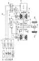
図1は、本発明の実施例に係るハイブリッド自動車の概略構成図である。図1に示すハイブリッド自動車20は、エンジン22と、エンジン22の出力軸としてのクランクシャフト26にダンパ28を介して接続された3軸式の動力分配統合機構30と、動力分配統合機構30に接続された発電可能なモータMG1と、動力分配統合機構30に接続された駆動軸としてのリングギヤ軸32aに取り付けられた減速ギヤ35と、この減速ギヤ35に接続されたモータMG2と、動力出力装置全体をコントロールするハイブリッド用電子制御ユニット(以下、「ハイブリッドECU」という)70とを備える。 FIG. 1 is a schematic configuration diagram of a hybrid vehicle according to an embodiment of the present invention. A
エンジン22は、例えばガソリンや軽油といった炭化水素系の燃料を用いて動力を出力可能な内燃機関として構成されている。エンジン22は、図2からわかるように、エアクリーナ122により清浄された空気をスロットルバルブ124を介して吸気ポートに取り入れると共に燃料噴射弁126からガソリンを噴射して吸入空気とガソリンとを混合させ、この混合気を吸気バルブ128を介して燃焼室に吸入すると共に点火プラグ130による電気火花によって爆発燃焼させて、そのエネルギにより押し下げられるピストン132の往復運動をクランクシャフト26の回転運動に変換するものである。エンジン22からの排気ガスは、一酸化炭素(CO)や炭化水素(HC)、窒素酸化物(NOx)といった有害成分を浄化する排ガス浄化触媒(三元触媒)を備えた浄化装置134を介して外部へと排出される。浄化装置134の排ガス浄化触媒は、白金(Pt)やパラジウム(Pd)等の酸化触媒と、ロジウム(Rh)等の還元触媒と、セリア(CeO2)等の助触媒等から構成されるとよい。この場合、酸化触媒の作用により排ガスに含まれるCOやHCが水(H2O)や二酸化炭素(CO2)に浄化され、還元触媒の作用により排ガスに含まれるNOxが窒素(N2)や酸素(O2)に浄化される。The
このように構成されるエンジン22は、エンジン用電子制御ユニット(以下、エンジンECUという)24により制御される。エンジンECU24は、図2に示すように、CPU24aを中心とするマイクロプロセッサとして構成されており、CPU24aの他に処理プログラムを記憶するROM24bと、データを一時的に記憶するRAM24cと、図示しない入出力ポートおよび通信ポートとを備える。例えば、エンジンECU24には、クランクシャフト26の回転位置を検出するクランクポジションセンサ140からのクランクポジション、エンジン22の冷却水の温度を検出する水温センサ142からの冷却水温、燃焼室内の圧力である筒内圧力を検出する圧力センサ143からの筒内圧力、燃焼室へ吸排気を行なう吸気バルブ128や排気バルブを開閉するカムシャフトの回転位置を検出するカムポジションセンサ144からのカムポジション、スロットルバルブ124のポジションを検出するスロットルバルブポジションセンサ146からのスロットルポジション、吸気管に設けられたエアフローメータ148からの信号、同様に吸気管に設けられた温度センサ149からの吸気温度、浄化装置134に設けられた温度センサ135からの触媒床温Tcat等が入力ポートを介して入力されている。また、エンジンECU24からは、エンジン22を駆動するための種々の制御信号、例えば、燃料噴射弁126への駆動信号や、スロットルバルブ124のポジションを調節するスロットルモータ136への駆動信号、イグナイタと一体化されたイグニッションコイル138への制御信号、吸気バルブ128の開閉タイミングを変更可能な可変バルブタイミング機構150への制御信号等が出力ポートを介して出力される。なお、エンジンECU24は、ハイブリッド用電子制御ユニット70と通信しており、ハイブリッド用電子制御ユニット70からの制御信号によりエンジン22を運転制御すると共に必要に応じてエンジン22の運転状態に関するデータをハイブリッドECU70に出力する。 The
動力分配統合機構30は、外歯歯車のサンギヤ31と、このサンギヤ31と同心円上に配置された内歯歯車のリングギヤ32と、サンギヤ31に噛合すると共にリングギヤ32に噛合する複数のピニオンギヤ33と、複数のピニオンギヤ33を自転かつ公転自在に保持するキャリア34とを備え、サンギヤ31とリングギヤ32とキャリア34とを回転要素として差動作用を行なう遊星歯車機構として構成されている。キャリア34にはエンジン22のクランクシャフト26が、サンギヤ31にはモータMG1が、リングギヤ32にはリングギヤ軸32aを介して減速ギヤ35がそれぞれ連結されており、動力分配統合機構30は、モータMG1が発電機として機能するときにはキャリア34から入力されるエンジン22からの動力をサンギヤ31側とリングギヤ32側にそのギヤ比に応じて分配し、モータMG1が電動機として機能するときにはキャリア34から入力されるエンジン22からの動力とサンギヤ31から入力されるモータMG1からの動力を統合してリングギヤ32側に出力する。リングギヤ32に出力された動力は、リングギヤ軸32aからギヤ機構60およびデファレンシャルギヤ62を介して、最終的には車両の駆動輪63a,63bに出力される。 The power distribution and
モータMG1およびモータMG2は、何れも発電機として作動することができると共に電動機として作動可能な周知の同期発電電動機として構成されており、インバータ41,42を介してバッテリ50と電力のやりとりを行なう。インバータ41,42とバッテリ50とを接続する電力ライン54は、各インバータ41,42が共用する正極母線および負極母線として構成されており、モータMG1,MG2の何れかで発電される電力を他のモータで消費することができるようになっている。したがって、バッテリ50は、モータMG1,MG2の何れかから生じた電力や不足する電力により充放電されることになる。なお、モータMG1,MG2により電力収支のバランスをとるものとすれば、バッテリ50は充放電されない。モータMG1,MG2は、何れもモータ用電子制御ユニット(以下、「モータECU」という)40により駆動制御されている。モータECU40には、モータMG1,MG2を駆動制御するために必要な信号、例えばモータMG1,MG2の回転子の回転位置を検出する回転位置検出センサ43,44からの信号や図示しない電流センサにより検出されるモータMG1,MG2に印加される相電流等が入力されており、モータECU40からは、インバータ41,42へのスイッチング制御信号が出力されている。モータECU40は、ハイブリッドECU70と通信しており、ハイブリッドECU70からの制御信号によってモータMG1,MG2を駆動制御すると共に必要に応じてモータMG1,MG2の運転状態に関するデータをハイブリッドECU70に出力する。 Both the motor MG1 and the motor MG2 are configured as well-known synchronous generator motors that can operate as a generator and operate as an electric motor, and exchange power with the
バッテリ50は、バッテリ用電子制御ユニット(以下、「バッテリECU」という)52によって管理されている。バッテリECU52には、バッテリ50を管理するのに必要な信号、例えば、バッテリ50の端子間に設置された図示しない電圧センサからの端子間電圧、バッテリ50の出力端子に接続された電力ライン54に取り付けられた図示しない電流センサからの充放電電流、バッテリ50に取り付けられた温度センサ51からの電池温度Tb等が入力されており、バッテリECU52は、必要に応じてバッテリ50の状態に関するデータを通信によりハイブリッドECU70やエンジンECU24に出力する。なお、バッテリECU52は、バッテリ50を管理するために電流センサにより検出された充放電電流の積算値に基づいて残容量SOCも算出している。 The
ハイブリッドECU70は、CPU72を中心とするマイクロプロセッサとして構成されており、CPU72の他に処理プログラムを記憶するROM74と、データを一時的に記憶するRAM76と、図示しない入出力ポートおよび通信ポートとを備える。ハイブリッドECU70には、イグニッションスイッチ80からのイグニッション信号、シフトレバー81の操作位置であるシフトポジションSPを検出するシフトポジションセンサ82からのシフトポジションSP、アクセルペダル83の踏み込み量を検出するアクセルペダルポジションセンサ84からのアクセル開度Acc、ブレーキペダル85の踏み込み量を検出するブレーキペダルポジションセンサ86からのブレーキペダルポジションBP、車速センサ88からの車速V等が入力ポートを介して入力される。ハイブリッドECU70は、上述したように、エンジンECU24やモータECU40、バッテリECU52と通信ポートを介して接続されており、エンジンECU24やモータECU40、バッテリECU52と各種制御信号やデータのやりとりを行なっている。 The
また、実施例のハイブリッド自動車20では、シフトレバー81のシフトポジションSPとして、駐車時に用いる駐車ポジション、後進走行用のリバースポジション、中立のニュートラルポジション、前進走行用の通常のドライブポジション(以下、「Dポジション」という)の他に、シーケンシャルシフトポジション(以下、「Sポジション」という)、アップシフト指示ポジションおよびダウンシフト指示ポジションが用意されている。シフトポジションSPとしてDポジションを選択すると、実施例のハイブリッド自動車20は、エンジン22が効率よく運転されるように駆動制御される。また、シフトポジションSPとしてSポジションを選択すれば、主として減速時に、車速Vに対するエンジン22の回転数の比を例えば6段階(SP1〜SP6)に変更することが可能となる。実施例では、運転者によりシフトレバー81がSポジションにセットされると、シフトポジションSPが5段目のSP5とされ、シフトポジションセンサ82によりシフトポジションSP=SP5である旨が検出される。以後、シフトレバー81がアップシフト指示ポジションにセットされるとシフトポジションSPが1段ずつ上げられる(アップシフトされる)一方、シフトレバー81がダウンシフト指示ポジションにセットされるとシフトポジションSPが1段ずつ下げられ(ダウンシフトされ)、シフトポジションセンサ82は、シフトレバー81の操作に応じて現在のシフトポジションSPを出力する。 In the
上述のように構成された実施例のハイブリッド自動車20では、運転者によるアクセルペダル83の踏み込み量に対応するアクセル開度Accと車速Vとに基づいて駆動軸としてのリングギヤ軸32aに出力すべき要求トルクTr*が計算され、この要求トルクTr*に対応する動力がリングギヤ軸32aに出力されるようにエンジン22とモータMG1とモータMG2とが運転制御される。エンジン22とモータMG1とモータMG2の運転制御モードとしては、要求動力に見合う動力がエンジン22から出力されるようにエンジン22を運転制御すると共にエンジン22から出力される動力のすべてが動力分配統合機構30とモータMG1とモータMG2とによってトルク変換されてリングギヤ軸32aに出力されるようモータMG1およびモータMG2を駆動制御するトルク変換運転モードや、要求動力とバッテリ50の充放電に必要な電力との和に見合う動力がエンジン22から出力されるようにエンジン22を運転制御すると共にバッテリ50の充放電を伴ってエンジン22から出力される動力の全部またはその一部が動力分配統合機構30とモータMG1とモータMG2とによるトルク変換を伴って要求動力がリングギヤ軸32aに出力されるようモータMG1およびモータMG2を駆動制御する充放電運転モード、エンジン22の運転を停止してモータMG2から要求動力に見合う動力をリングギヤ軸32aに出力するように運転制御するモータ運転モード等がある。 In the
次に、実施例のハイブリッド自動車20の動作、特に、運転者によりシフトポジションSPとしてSポジションが選択されているときのハイブリッド自動車20の動作について説明する。ここでは、Sポジション選択時におけるハイブリッド自動車20の動作をアクセル操作状態がアクセルオン状態にある場合と、アクセル操作状態がアクセルオフ状態にある場合とに分けて説明する。 Next, the operation of the
図3は、運転者によりシフトポジションSPとしてSポジションが選択されており、かつアクセル操作状態がアクセルオン状態にあるときに、ハイブリッドECU70により実行される駆動制御ルーチンの一例を示すフローチャートである。このルーチンは、アクセル操作状態がアクセルオン状態にあるときに所定時間毎(例えば数msec毎)に繰り返し実行される。図3の駆動制御ルーチンが開始されると、ハイブリッドECU70のCPU72は、まず、アクセルペダルポジションセンサ84からのアクセル開度Acc、車速センサ88からの車速V、モータMG1,MG2の回転数Nm1,Nm2、シフトポジションセンサ82からのシフトポジションSP、バッテリ50が充放電すべき充放電要求パワーPb*、バッテリ50の残容量SOC、バッテリ50の入出力制限Win,Woutといった制御に必要なデータの入力処理を実行する(ステップS100)。この場合、モータMG1,MG2の回転数Nm1,Nm2は、回転位置検出センサ43,44により検出されるモータMG1,MG2の回転子の回転位置に基づいて計算されたものをモータECU40から通信により入力するものとした。充放電要求パワーPb*や残容量SOCは、バッテリECU52から通信により入力するものとした。バッテリ50の充電に許容される電力である充電許容電力としての入力制限Winと、その放電に許容される電力である放電許容電力としての出力制限Woutとは、温度センサ51により検出されたバッテリ50の電池温度Tbとバッテリ50の残容量SOCとに基づいて設定されたものをバッテリECU52から通信により入力するものとした。なお、バッテリ50の入出力制限Win,Woutは、電池温度Tbに基づいて入出力制限Win,Woutの基本値を設定し、バッテリ50の残容量(SOC)に基づいて出力制限用補正係数と入力制限用補正係数とを設定し、設定した入出力制限Win,Woutの基本値に補正係数を乗じて設定することが可能である。図4に電池温度Tbと入出力制限Win,Woutとの関係の一例を示し、図5にバッテリ50の残容量(SOC)と入出力制限Win,Woutの補正係数との関係の一例を示す。 FIG. 3 is a flowchart showing an example of a drive control routine executed by the
ステップS100のデータ入力処理の後、入力したアクセル開度Acc、車速VおよびシフトポジションSPに基づいて駆動輪63a,63bに接続された駆動軸としてのリングギヤ軸32aに出力すべき要求トルクTr*と、走行に際して車両全体に要求される要求パワーP*とを設定する(ステップS110)。実施例では、アクセル開度Acc、車速VおよびシフトポジションSPと要求トルクTr*との関係を予め定めて要求駆動力の設定可能範囲を規定する要求トルク設定用マップとしてROM74に記憶しておき、アクセル開度Acc、車速VおよびシフトポジションSPが与えられると当該マップからこれらに対応する要求トルクTr*を導出して設定するものとした。なお、実施例では、シフトポジションSPがDポジションである場合とSP1〜SP6の何れかである場合とで、アクセルオン状態にあるときには同一の制約のもとで要求トルクTr*が設定される一方、アクセル開度Accが0%(アクセルオフ)のときに設定される要求トルク(制動トルク)Tr*が相違するものとした。図6に要求トルク設定用マップの一例を示す。また、実施例では、設定した要求トルクTr*にリングギヤ軸32aの回転数Nr(=Nm2/Gr)を乗じたものとバッテリ50が充放電すべき充放電要求パワーPb*とロスLossとの和として要求パワーP*を設定するものとした。 After the data input process in step S100, the required torque Tr * to be output to the
続いて、設定した要求パワーP*が所定の閾値Pref以上であるか否かを判定する(ステップS120)。ここで用いられる閾値Prefは、エンジン22に動力(トルク)を出力させるべきか否かを判定するために、エンジン22やモータMG2の特性等に基づいて定められ、エンジン22を比較的効率よく運転することができる領域における下限のパワーまたはその近傍の値とされる。そして、ステップS120にて要求パワーP*が閾値Pref以上であると判断された場合、当該要求パワーP*をエンジン22に出力させるものとし、要求パワーP*に基づいてエンジン22の仮目標回転数Netmpと仮目標トルクTetmpとを設定する(ステップS130)。ここでは、エンジン22を効率よく動作させる動作ラインと要求パワーP*とに基づいて仮目標回転数Netmpと仮目標トルクTetmpとを設定するものとした。図7に、エンジン22の動作ラインの一例と仮目標回転数Netmpと仮目標トルクTetmpとの相関曲線の一例とを示す。同図に示すように、仮目標回転数Netmpと仮目標トルクTetmpは、動作ラインと要求パワーP*(Netmp×Tetmp)が一定となること示す相関曲線との交点から求めることができる。こうして仮目標回転数Netmpと仮目標トルクTetmpとを設定したならば、次に、ステップS100で入力したシフトポジションSPに基づいてエンジン22の回転数の下限値としての下限エンジン回転数Neminを設定する(ステップS140)。下限エンジン回転数Neminは、シフトポジションSP1〜SP6ごとに、エンジン22からの動力を増減できる幅が充分広くなり、かつ動力の迅速な増減を可能にする最小の回転数として予め定められており、ROM74に記憶されている。なお、下限エンジン回転数Neminは、全車速域あるいは車速Vが所定値未満である場合、シフトポジションSPと車速Vとに基づいて定められてもよく、この場合には、予めシフトポジションSPと車速Vと下限エンジン回転数Neminとの関係を定めるマップを作成してROM74に記憶しておけばよい。 Subsequently, it is determined whether or not the set required power P * is equal to or greater than a predetermined threshold value Pref (step S120). The threshold value Pref used here is determined based on the characteristics of the
下限エンジン回転数Neminを設定したならば、当該下限エンジン回転数NeminとステップS130で設定した仮目標回転数Netmとを比較し(ステップS150)、仮目標回転数Netmpが下限エンジン回転数Nemin以上であれば、エンジン22からの動力を増減できる幅が充分広く、かつ動力の迅速な増減が可能であるとみなして、ステップS130で設定した仮目標回転数Netmpをエンジン22の目標回転数Ne*として設定すると共に、ステップS130で設定した仮目標トルクTetmpをエンジン22の目標トルクTe*として設定する(ステップS160)。これに対して、仮目標回転数Netmpが下限エンジン回転数Nemin未満であれば、エンジン22からの動力を増減できる幅が充分広くなり、かつ動力の迅速な増減を可能とするように、ステップS140で設定した下限エンジン回転数Neminをエンジン22の目標回転数Ne*として設定すると共に、設定した目標回転数Ne*(=Netmp)と要求パワーP*とからエンジン22の目標トルクTe*(P*/Ne*)を計算してエンジン22の目標トルクTe*として設定する(ステップS170)。このように、シフトポジションSPとしてSポジションが選択されているときには、エンジン22の目標回転数Ne*がシフトポジションSP1〜SP6ごとに定められた下限回転数Nemin以上とされるので、運転者の加減速要求に応答性よく対応することが可能となる。 If the lower limit engine speed Nemin is set, the lower limit engine speed Nemin is compared with the temporary target speed Netm set in step S130 (step S150), and the temporary target speed Netmp is equal to or higher than the lower limit engine speed Nemin. If so, it is considered that the range in which the power from the
こうしてエンジン指令としてのエンジン22の目標回転数Ne*と目標トルクTe*とを設定したならば、設定した目標回転数Ne*とリングギヤ軸32aの回転数Nr(=Nm2/Gr)と動力分配統合機構30のギヤ比ρとに基づいて次式(1)を用いた計算によりモータMG1の目標回転数Nm1*を求めると共に、求めた目標回転数Nm1*と現在の回転数Nm1とに基づいて次式(2)を用いた計算によりモータMG1のトルク指令Tm1*を設定する(ステップS180)。式(1)は、動力分配統合機構30の回転要素に関連する力学的な関係式である。図8にアクセルオン時における動力分配統合機構30における各回転要素における回転数とトルクとの力学的な関係を表す共線図の一例を示す。図中、左のS軸はモータMG1の回転数Nm1に一致するサンギヤ31の回転数を示し、C軸はエンジン22の回転数Neに一致するキャリア34の回転数を示し、R軸はモータMG2の回転数Nm2を減速ギヤ35のギヤ比Grで除したリングギヤ32の回転数Nrを示す。また、R軸上の2つの太線矢印は、モータMG1からトルクTm1を出力したときにこのトルク出力によりリングギヤ軸32aに作用するトルクと、モータMG2から出力されるトルクTm2が減速ギヤ35を介してリングギヤ軸32aに作用するトルクとを示す。モータMG1の目標回転数Nm1*を求めるための式(1)は、この共線図における回転数の関係を用いれば容易に導くことができる。なお、式(1)中のρは、動力分配統合機構30のギヤ比(サンギヤ31の歯数/リングギヤ32の歯数)であり、式(2)中、右辺第2項の「k1」は比例項のゲインであり、右辺第3項の「k2」は積分項のゲインである。 If the target rotational speed Ne * and the target torque Te * of the
Nm1*=Ne*・(1+ρ)/ρ−Nm2/(Gr・ρ) …(1)
Tm1*=前回Tm1*+k1(Nm1*−Nm1)+k2∫(Nm1*−Nm1)dt …(2)Nm1 * = Ne * ・ (1 + ρ) / ρ−Nm2 / (Gr ・ ρ) (1)
Tm1 * = previous Tm1 * + k1 (Nm1 * −Nm1) + k2∫ (Nm1 * −Nm1) dt (2)
トルク指令Tm1*を設定すると、次式(3)および式(4)に従ってステップS100で入力したバッテリ50の出力制限Woutまたは入力制限Winと、設定したモータMG1のトルク指令Tm1*に現在のモータMG1の回転数Nm1を乗じて得られるモータMG1の消費電力との偏差をモータMG2の回転数Nm2で除することによりモータMG2から出力してもよいトルクの上下限としてのトルク制限Tmax,Tminを計算する(ステップS190)。更に、要求トルクTr*とトルク指令Tm1*と動力分配統合機構30のギヤ比ρと減速ギヤ35のギヤ比Grとを用いて次式(5)に従ってモータMG2から出力すべきトルクとしての仮モータトルクTm2tmpを計算し(ステップS200)、計算した仮モータトルクTm2tmpをトルク制限Tmax,Tminで制限することによりモータMG2のトルク指令Tm2*を設定する(ステップS210)。このようにしてモータMG2のトルク指令Tm2*を設定することにより、リングギヤ軸32aに出力する要求トルクTr*を基本的にバッテリ50の入出力制限Win,Woutの範囲内に制限したトルクとして設定することができる。なお、式(5)は、図8の共線図から容易に導き出すことができる。こうしてエンジン22の目標回転数Ne*や目標トルクTe*、モータMG1,MG2のトルク指令Tm1*,Tm2*を設定すると、エンジン指令としてのエンジン22の目標回転数Ne*および目標トルクTe*をエンジンECU24に、モータMG1,MG2のトルク指令Tm1*,Tm2*をモータECU40にそれぞれ送信し(ステップS220)、本ルーチンを一旦終了させる。目標回転数Ne*と目標トルクTe*とを受信したエンジンECU24は、目標回転数Ne*と目標トルクTe*とを得るための制御を実行する。また、トルク指令Tm1*,Tm2*を受信したモータECU40は、トルク指令Tm1*に従ってモータMG1が駆動されると共にトルク指令Tm2*に従ってモータMG2が駆動されるようにインバータ41,42のスイッチング素子のスイッチング制御を行なう。 When the torque command Tm1 * is set, the current motor MG1 is added to the output limit Wout or the input limit Win of the
Tmax=(Wout*−Tm1*・Nm1)/Nm2 …(3)
Tmin=(Win−Tm1*・Nm1)/Nm2 …(4)
Tm2tmp=(Tr*+Tm1*/ρ)/Gr …(5)Tmax = (Wout * −Tm1 * ・ Nm1) / Nm2 (3)
Tmin = (Win−Tm1 * ・ Nm1) / Nm2 (4)
Tm2tmp = (Tr * + Tm1 * / ρ) / Gr (5)
一方、例えば運転者によりアクセル開度Accが比較的大きい状態(例えば全開に近い状態)から比較的小さい状態(例えば5%程度)まで急激に減じられ、アクセル操作状態がアクセルオン状態のままでアクセル開度が減じられることによる減速要求がなされたような場合等には、ステップS110にて車両全体に要求される要求パワーP*が比較的小さな値に設定されることから、ステップS120にて要求パワーP*が閾値Pref未満であると判断されることがある。このような場合には、まず、ステップS100で入力したバッテリ50の残容量SOCが予め定められた上限値SOC1以下であるか否かを判定し(ステップS230)、残容量SOCが上限値SOC1以下であれば、ステップS100で入力したバッテリ50の入力制限Winが充電電力として所定の充電限界値Win1以下であるか否かを判定する(ステップS240)。ステップS230にて用いられる上限値SOC1と、ステップS240にて用いられる充電限界値Win1とは、後述のようにして減速要求時の要求駆動力を燃料カット無しにエンジン22の実質的な自立運転を伴って得る際にモータMG1およびMG2により入出力される電力に基づいてそれぞれ定められる。 On the other hand, for example, the driver suddenly reduces the accelerator opening Acc from a relatively large state (for example, a state close to full opening) to a relatively small state (for example, about 5%), and the accelerator operation state remains in the accelerator on state. In the case where a deceleration request is made by reducing the opening, the required power P * required for the entire vehicle is set to a relatively small value in step S110, so that the request is requested in step S120. The power P * may be determined to be less than the threshold value Pref. In such a case, first, it is determined whether or not the remaining capacity SOC of the
残容量SOCが上限値SOC1以下であり、かつバッテリ50の入力制限Winが充電限界値Win1以下であれば、エンジン指令としてエンジン22の爆発燃焼(ファイアリング)を継続させるための指令を設定すると共に、エンジン22が実質的にトルクの出力を行なうことなく自立運転するように、エンジン22の目標回転数Ne*を当該爆発燃焼の継続時の回転数Ne0に設定する(ステップS250)。実施例では、回転数Ne0は、例えばアイドル時の回転数(800〜1000rpm)であるものとした。続いて、設定した目標回転数Ne*(=Ne0)とステップS100で入力したエンジン22の回転数Neとに基づいて次式(6)に従った計算を行い、爆発燃焼を継続させた状態でエンジン22の回転数Neが目標回転数Ne*(=Ne0)に至るようにするためのモータMG1のトルク指令Tm1*を設定する(ステップS260)。式(6)は、エンジン22の爆発燃焼の継続を伴ってエンジン22の回転数Neを目標回転数Ne*にするためのフィードバック制御における関係式であり、式(2)中、右辺第1項の「k1」は比例項のゲインであり、右辺第2項の「k2」は積分項のゲインである。これらのゲイン「k1」,「k2」は、エンジン22の爆発燃焼を継続する必要から、エンジン22から比較的大きなトルクを出力しているときに比べて小さな値に設定されている。 If the remaining capacity SOC is equal to or less than the upper limit value SOC1 and the input limit Win of the
こうしてトルク指令Tm1*を設定すると、設定したトルク指令Tm1*を用いてモータMG2のトルク指令Tm2*を設定し(ステップS190〜S210)、エンジン指令(ファイアリング指令および目標回転数Ne*)をエンジンECU24に、トルク指令Tm1*,Tm2*をモータECU40に送信して(ステップS220)、本ルーチンを一旦終了させる。このように、アクセルオン状態で減速要求がなされたときにエンジン22の爆発燃焼を継続させる場合には、上述のようにしてモータMG1を駆動制御することにより、燃料カット無しにエンジン22の回転数Neを目標回転数Ne*(=Ne0)まで迅速に低下させ、ハイブリッド自動車20を減速させることが可能となる。この際、エンジンECU24は、失火を生じさせない程度に吸入空気の量が確保されるようにスロットルバルブ124の開度を小さく設定する。図9にアクセルオン状態でエンジン22の爆発燃焼を継続させるときの動力分配統合機構30における各回転要素の回転数とトルクとの力学的な関係を表す共線図の一例を示す。同図からわかるように、エンジン22を回転数Ne0で運転したときには、エンジン22から若干の駆動トルクが出力され、この駆動トルクが出力軸としてのリングギヤ軸32aに作用するので、モータMG2は、要求トルク(制動トルク)Tr*に基づくトルクからこの駆動トルクを減じた分のトルクを出力することになる。 When the torque command Tm1 * is set in this way, the torque command Tm2 * of the motor MG2 is set using the set torque command Tm1 * (steps S190 to S210), and the engine command (firing command and target rotational speed Ne *) is set to the engine. Torque commands Tm1 * and Tm2 * are transmitted to the
Tm1*=k1・(Ne*−Ne)+k2∫(Ne*−Ne)・dt …(6) Tm1 * = k1 ・ (Ne * −Ne) + k2∫ (Ne * −Ne) ・ dt (6)
ここで、図9において二点鎖線で示すように車速Vが高い状態でアクセルオン状態のままアクセル開度Accが急激に減じられた場合にエンジン22の爆発燃焼を継続させるとすれば、モータMG1によりエンジン22の回転数を急峻に目標回転数Ne0まで低下させる必要があり、これに伴ってモータMG1により回生される電力が大きくなる。従って、バッテリ50の残容量SOCや、残容量SOC等に基づいて設定されるバッテリ50の入力制限Winの値によっては、燃料カットを行わずにエンジン22を実質的に自立運転させるに際してモータMG1により回生される電力をバッテリ50に蓄えられなくなるおそれもある。このため、ステップS230にてバッテリ50の残容量SOCが上限値SOC1未満であると判断された場合や、ステップS240にてバッテリ50の入力制限Winが充電電力として充電限界値Win1未満であると判断された場合には、燃料カットを禁止し得ないとみなし、エンジン22に対する燃料噴射を一時的に停止する燃料カットを実行させるための指令を設定すると共に(ステップS270)、モータMG1のトルク指令Tm1*に値0を設定する(ステップS280)。そして、設定したトルク指令Tm1*(=0)を用いてモータMG2のトルク指令Tm2*を設定し(ステップS190〜S210)、エンジン指令(燃料カット指令)をエンジンECU24に、トルク指令Tm1*,Tm2*をモータECU40に送信して(ステップS220)、本ルーチンを一旦終了させる。このように、燃料カットを実行することにより、エンジン22の回転数を速やかに低下させ、ハイブリッド自動車20を減速させることが可能となる。図10にアクセルオン状態で燃料カットを実行したときの動力分配統合機構30における各回転要素の回転数とトルクとの力学的な関係を表す共線図の一例を示す。 Here, as shown by the alternate long and two short dashes line in FIG. 9, if the
上述のように、実施例のハイブリッド自動車20では、シフトポジションSPがSポジションに設定されて走行に要求される要求トルクTr*の設定可能範囲を規定するシフトポジションSP1〜SP6の任意の選択(手動選択)が許容されている状態でアクセルオン状態での減速要求がなされたときに、バッテリ50の状態、すなわち残容量SOCや入力制限Winに基づいて燃料カットを禁止し得ないと判断された場合には、エンジン22における燃料カットを伴って設定された要求トルクTr*に基づく駆動力が出力されるようにエンジン22とモータMG1およびMG2とが制御される(ステップS270,S280,S190〜S220)。また、シフトポジションSPがSポジションが設定された状態でアクセルオン状態での減速要求がなされたときに、バッテリ50の残容量SOCや入力制限Winに基づいて燃料カットを禁止し得ると判断された場合には、エンジン22が目標回転数Ne0で実質的に自立運転されると共に設定された要求トルクTr*に基づく駆動力が出力されるようにエンジン22とモータMG1およびMG2とが制御される(ステップS250,S260,S190〜S220)。 As described above, in the
引き続き、運転者によりシフトポジションSPとしてSポジションが選択されており、かつアクセル操作状態がアクセルオフ状態にあるときのハイブリッド自動車20の動作について説明する。図11は、運転者によりシフトポジションSPとしてSポジションが選択されており、かつアクセル操作状態がアクセルオフ状態にあるときに、ハイブリッドECU70により実行される駆動制御ルーチンの一例を示すフローチャートである。このルーチンもアクセル操作状態がアクセルオフ状態にあるときに所定時間毎(例えば数msec毎)に繰り返し実行される。図11の駆動制御ルーチンが開始されると、ハイブリッドECU70のCPU72は、まず、車速センサ88からの車速V、モータMG1,MG2の回転数Nm1,Nm2、シフトポジションセンサ82からのシフトポジションSP、バッテリ50が充放電すべき充放電要求パワーPb*、バッテリ50の残容量SOC、バッテリ50の入力制限Winといった制御に必要なデータの入力処理を実行する(ステップS300)。各データの入力手順については、図3のルーチンの場合と同様とされる。ステップS300のデータ入力処理の後、車速VおよびシフトポジションSPに基づいて駆動輪63a,63bに接続された駆動軸としてのリングギヤ軸32aに出力すべき要求トルク(制動トルク)Tr*と、走行に際して車両全体に要求される要求パワーP*とを設定する(ステップS310)。実施例において、要求トルクTr*の設定処理は、図6に例示される要求トルク設定用マップから車速VとシフトポジションSPとに対応するアクセル開度Accが0%のときの要求トルクTr*を導出して設定するものとした。また、要求パワーP*は、図3のルーチンの場合と同様にして設定するものとした。続いて、ステップS300で入力したバッテリ50の残容量SOCが予め定められた上限値SOC1以下であるか否かを判定し(ステップS320)、残容量SOCが上限値SOC1以下であれば、ステップS300で入力したバッテリ50の入力制限Winが所定の充電限界値Win1以下であるか否かを判定する(ステップS330)。上限値SOC1と充電限界値Win1とは、それぞれ図3のルーチンの場合と同じ値とされる。 Next, the operation of the
残容量SOCが上限値SOC1以下であり、かつバッテリ50の入力制限Winが充電限界値Win1以下であれば、エンジン指令としてエンジン22の爆発燃焼(ファイアリング)を継続させるための指令を設定すると共に(ステップS340)、エンジン22が実質的にトルクの出力を行なうことなく自立運転するように、エンジン22の目標回転数Ne*を当該爆発燃焼の継続時の回転数Ne0に設定する(ステップS350)。回転数Ne0は、図3のルーチンの場合と同様に、例えばアイドル時の回転数(800〜1000rpm)とされる。続いて、設定した目標回転数Ne*(=Ne0)とステップS300で入力したエンジン22の回転数Neとに基づいて上記式(6)に従った計算を行い、爆発燃焼を継続させた状態でエンジン22の回転数Neが目標回転数Ne*(=Ne0)に至るようにするためのモータMG1のトルク指令Tm1*を設定する(ステップS360)。そして、トルク指令Tm1*を設定すると、ステップS300で入力したバッテリ50の入力制限Winと、設定したモータMG1のトルク指令Tm1*に現在のモータMG1の回転数Nm1を乗じて得られるモータMG1の消費電力との偏差をモータMG2の回転数Nm2で除することによりモータMG2から出力してもよいトルクの下限としてのトルク制限Tminを計算する(ステップS370)。更に、要求トルクTr*とトルク指令Tm1*と動力分配統合機構30のギヤ比ρと減速ギヤ35のギヤ比Grとを用いて図3のルーチンにおけるステップS200と同様にしてモータMG2から出力すべきトルクとしての仮モータトルクTm2tmpを計算し(ステップS380)、計算した仮モータトルクTm2tmpをトルク制限Tminで制限することによりモータMG2のトルク指令Tm2*を設定する(ステップS390)。このようにしてモータMG2のトルク指令Tm2*を設定することにより、リングギヤ軸32aに出力する要求トルクTr*を基本的にバッテリ50の入力制限Winで制限したトルクとして設定することができる。そして、エンジン指令(ファイアリング指令および目標回転数Ne*)やモータMG1,MG2のトルク指令Tm1*,Tm2*を設定すると、エンジン指令をエンジンECU24に、モータMG1,MG2のトルク指令Tm1*,Tm2*をモータECU40にそれぞれ送信し(ステップS400)、本ルーチンを一旦終了させる。 If the remaining capacity SOC is equal to or less than the upper limit value SOC1 and the input limit Win of the
このように、アクセルオフに基づく減速要求がなされたときにエンジン22の爆発燃焼を継続させる場合には、上述のようにしてモータMG1およびMG2を駆動制御することにより、燃料カット無しにエンジン22の回転数Neを目標回転数Ne*(=Ne0)まで迅速に低下させつつ、モータMG2の回生により制動力を発生させてハイブリッド自動車20を減速させることが可能となる。この場合も、エンジンECU24は、失火を生じさせない程度に吸入空気の量が確保されるようにスロットルバルブ124の開度を小さく設定する。図12にアクセルオフ状態でエンジン22の爆発燃焼を継続させるときの動力分配統合機構30における各回転要素の回転数とトルクとの力学的な関係を表す共線図の一例を示す。また、アクセルオフ状態においても、エンジン22を回転数Ne0で運転したときには、図12に示すように、エンジン22から出力軸としてのリングギヤ軸32aに若干の駆動トルクが出力されるので、モータMG2は、要求トルク(制動トルク)Tr*に基づくトルクと当該駆動トルクをキャンセルする分のトルクとの和を出力することになる。 As described above, when the explosion combustion of the
ただし、このようなアクセルオフ状態においても、図12において二点鎖線で示すように車速Vが高い状態でアクセルオン状態のままアクセル開度Accが急激に減じられた場合にエンジン22の爆発燃焼を継続させるとすると、モータMG1によりエンジン22の回転数を急峻に目標回転数Ne0まで低下させる必要があり、これに伴ってモータMG1により回生される電力が大きくなる。また、アクセルオフ時には、図6からわかるように車速が高いほど、またシフトポジションSPが下段側(SP1側)にあるほど、設定される要求トルクTr*が制動力として大きくなることから、モータMG2に要求される回生制動力も大きくなり、その分だけモータMG2からバッテリ50に入力される電力も大きくなる。従って、バッテリ50の残容量SOCや、残容量SOC等に基づいて設定されるバッテリ50の入力制限Winの値によっては、燃料カットを行わずにエンジン22を実質的に自立運転させるに際してモータMG1により回生される電力をバッテリ50に蓄えられなくなるおそれもある。 However, even in such an accelerator-off state, as shown by a two-dot chain line in FIG. 12, when the accelerator opening degree Acc is sharply reduced while the vehicle speed V is high and the accelerator is in the on-state, the
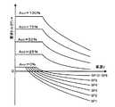
このため、ステップS320にてバッテリ50の残容量SOCが上限値SOC1未満であると判断された場合や、ステップS330にてバッテリ50の入力制限Winが充電電力として充電限界値Win1未満であると判断された場合には、燃料カットを禁止し得ないとみなし、エンジン22に対する燃料噴射を一時的に停止する燃料カットを実行させるための指令を設定した上で(ステップS410)、いわゆるエンジンブレーキにより制動力の一部をまかなうべく、シフトポジションSPと車速Vとに基づいてエンジン22の目標回転数Ne*を設定する(ステップS420)。実施例では、Sポジション選択時のために、SP1からSP6までのシフトポジションSPと車速Vとエンジン22の目標回転数Ne*との関係を予め定めてSポジション選択時用の運転ポイント制約たる目標回転数設定用マップとしてROM74に記憶しておき、シフトポジションSPと車速Vとが与えられると当該マップから両者に対応するエンジン22の目標回転数Ne*を導出して設定するものとした。Sポジション選択時に用いられる目標回転数設定用マップの一例を図13に示す。こうしてエンジン22の目標回転数Ne*を設定したならば、上述のステップS360からS400の処理を実行し、本ルーチンを一旦終了させる。このように、アクセルオフに基づく減速要求がなされたときに燃料カットを実行すると共に上述のようにモータMG1およびMG2を駆動制御すれば、駆動軸としてのリングギヤ軸32aに、エンジン22からのエンジンブレーキによる制動トルク(直達トルク=−1/ρ・Tm1*)とモータMG2からの回生による制動力とを出力することが可能となり、その分だけモータMG2の回生によりバッテリ50に入力される電力を減らすことができる。特に車速Vがある程度高く、かつシフトポジションSPが下段側にあると、図6からわかるように要求トルクとして比較的大きな制動トルクが設定され、図13からわかるようにエンジン22の目標回転Ne*が比較的高く設定され、モータMG1等のモータリングにより、エンジン22の回転数が高く保たれることから、その分だけモータMG2の負担を小さくすることができる。図14に、アクセルオフ状態で燃料カットを実行したときの動力分配統合機構30における各回転要素の回転数とトルクとの力学的な関係を表す共線図の一例を示す。 For this reason, when it is determined in step S320 that the remaining capacity SOC of the
上述のように、実施例のハイブリッド自動車20では、シフトポジションSPがSポジションに設定されてシフトポジションSP1〜SP6の任意の選択が許容されている状態でアクセルオフに基づく減速要求がなされたときに、バッテリ50の状態、すなわち残容量SOCや入力制限Winに基づいて燃料カットを禁止し得ないと判断された場合には、エンジン22における燃料カットを伴って設定された要求トルクTr*に基づく駆動力が出力されるようにエンジン22とモータMG1およびMG2とが制御される(S410,S420,S360〜S400)。また、シフトポジションSPがSポジションが設定された状態でアクセルオン状態での減速要求がなされたときに、バッテリ50の残容量SOCや入力制限Winに基づいて燃料カットを禁止し得ると判断された場合には、エンジン22が目標回転数Ne0で実質的に自立運転されると共に設定された要求トルクTr*に基づく駆動力が出力されるようにエンジン22とモータMG1およびMG2とが制御される(S340〜S400)。 As described above, in the
以上説明したように、実施例のハイブリッド自動車20では、シフトポジションSPがSポジションに設定されてシフトポジションSP1〜SP6の任意の選択が許容されている状態で、アクセルオン状態での減速要求やアクセルオフに基づく減速要求がなされたときに、バッテリ50の状態、すなわち残容量SOCや入力制限Winから燃料カットを禁止せざるを得ない場合を除いて、燃料カットを実行することなくエンジン22の実質的な自立運転を伴いながら要求トルクTr*に基づく駆動力(制動力)を得ている。すなわち、運転者にシフトポジションSP1〜SP6の任意の選択が許容されている場合、アクセル開度Accが急激に減じられることによるアクセルオン状態での減速要求やアクセルオフに基づく減速要求がなされると、通常、燃料カットが実行され、それにより浄化装置134の排ガス浄化触媒に多量の空気が送り込まれて当該触媒に酸素が付着することに起因したNOxの浄化性能の低下を招くおそれがある。従って、バッテリ50の状態から燃料カットを禁止せざるを得ない場合を除いて、燃料カットを実行することなくエンジン22の実質的な自立運転を伴いながら要求トルクTr*に基づく駆動力(制動力)を得るようにすれば、燃料カットに起因して多量の空気が浄化装置134に送り込まれることにより排ガス浄化触媒の浄化性能の低下を抑制することが可能となり、ひいてはエミッションの改善を図ることができる。 As described above, in the
また、上述のように、減速要求時の要求トルクTr*を燃料カット無しにエンジン22の実質的な自立運転を伴って得る際にモータMG1およびMG2より入出力される電力に基づいて閾値としての上限値SOC1および充電限界値Win1をそれぞれ定め、バッテリ50の残容量SOCが上限値SOC1以下であるか、あるいはバッテリ50の状態に基づいて設定される充電許容電力としての入力制限Winが充電限界値Win1以下である場合に燃料カットを禁止し得ると判断すれば、バッテリ50の状態に基づいて燃料カットを禁止し得るか否かをより適正に判定すると共に、適切なタイミングで燃料カットの禁止を解除してバッテリ50の過充電による劣化を抑制することが可能となる。 Further, as described above, the threshold value based on the electric power input / output from the motors MG1 and MG2 when the required torque Tr * at the time of the deceleration request is obtained with substantial self-sustained operation of the
なお、上記実施例のハイブリッド自動車20は、シフトレバー81のシフトポジションに、運転者にシフトポジションSP1〜SP6の任意の選択を許容するSポジションが含まれるものとして説明したが、本発明の適用対象はこれに限られるものではない。すなわち、シフトレバー81のシフトポジションSPに、主として例えば下り坂を比較的高速で走行しているような場合に選択され、それに対応する駆動力の設定可能範囲がDポジションに比べて動力範囲の下限が小さく定められているブレーキポジションが用意されている場合、ブレーキポジションが選択されたときに、図3や図11の駆動制御ルーチンを実行するようにしてもよい。 In the
以上、実施例を用いて本発明の実施の形態について説明したが、本発明は上記実施例に何ら限定されるものではなく、本発明の要旨を逸脱しない範囲内において、様々な変更をなし得ることはいうまでもない。 The embodiments of the present invention have been described above using the embodiments. However, the present invention is not limited to the above embodiments, and various modifications can be made without departing from the scope of the present invention. Needless to say.
すなわち、上記実施例のハイブリッド自動車20では、駆動軸としてのリングギヤ軸32aとモータMG2とがモータMG2の回転数を減速してリングギヤ軸32aに伝達する減速ギヤ35を介して連結しているが、減速ギヤ35の代わりに、例えばHi,Loの2段の変速段あるいは3段以上の変速段を有し、モータMG2の回転数を変速してリングギヤ軸32aに伝達する変速機を採用してもよい。 That is, in the
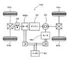
また、上記実施例のハイブリッド自動車20では、モータMG2の動力を減速ギヤ35により減速してリングギヤ軸32aに出力しているが、図15に示す変形例としてのハイブリッド自動車120のように、モータMG2の動力を変速機65により変速してリングギヤ軸32aが接続された車軸(駆動輪63a,63bが接続された車軸)とは異なる車軸(図15中、車輪63c,63dに接続された車軸)に伝達するようにしてもよい。 In the
更に、上記各実施例のハイブリッド自動車20、20Bは、エンジン22の動力を動力分配統合機構30を介して駆動輪63a,63bに接続された駆動軸としてのリングギヤ軸32aに出力するものであるが、図16に示す変形例としてのハイブリッド自動車220のように、エンジン22のクランクシャフト26に接続されたインナーロータ232と駆動輪63a,63bに動力を出力する駆動軸に接続されたアウターロータ234とを有し、エンジン22の動力の一部を駆動軸に伝達すると共に残余の動力を電力に変換する対ロータ電動機230を備えるものであってもよい。 Furthermore, the
20,120,220 ハイブリッド自動車、22 エンジン、24 エンジン用電子制御ユニット(エンジンECU)、24a,72 CPU、24b,74 ROM、24c,76 RAM、26 クランクシャフト、28 ダンパ、30 動力分配統合機構、31 サンギヤ、32 リングギヤ、32a リングギヤ軸、33 ピニオンギヤ、34 キャリア、35 減速ギヤ、40 モータ用電子制御ユニット(モータECU)、41,42 インバータ、43,44 回転位置検出センサ、50 バッテリ、51 温度センサ、52 バッテリ用電子制御ユニット(バッテリECU)、54 電力ライン、60 ギヤ機構、62 デファレンシャルギヤ、63a,63b 駆動輪、63c,63d 車輪、65 変速機、70 ハイブリッド用電子制御ユニット(ハイブリッドECU)、80 イグニッションスイッチ、81 シフトレバー、82 シフトポジションセンサ、83 アクセルペダル、84 アクセルペダルポジションセンサ、85 ブレーキペダル、86 ブレーキペダルポジションセンサ、88 車速センサ、122 エアクリーナ、124 スロットルバルブ、126 燃料噴射弁、128 吸気バルブ、130 点火プラグ、132 ピストン、134 浄化装置、135 温度センサ、136 スロットルモータ、138 イグニッションコイル、140 クランクポジションセンサ、142 水温センサ、143 圧力センサ、144 カムポジションセンサ、146 スロットルバルブポジションセンサ、148 エアフローメータ、149 温度センサ、150 可変バルブタイミング機構、230 対ロータ電動機、232 インナーロータ、234 アウターロータ、MG1,MG2 モータ。
20, 120, 220 Hybrid vehicle, 22 engine, 24 engine electronic control unit (engine ECU), 24a, 72 CPU, 24b, 74 ROM, 24c, 76 RAM, 26 crankshaft, 28 damper, 30 power distribution integration mechanism, 31 sun gear, 32 ring gear, 32a ring gear shaft, 33 pinion gear, 34 carrier, 35 reduction gear, 40 electronic control unit for motor (motor ECU), 41, 42 inverter, 43, 44 rotational position detection sensor, 50 battery, 51 temperature sensor , 52 battery electronic control unit (battery ECU), 54 power line, 60 gear mechanism, 62 differential gear, 63a, 63b driving wheel, 63c, 63d wheel, 65 transmission, 70 hybrid electronic control unit (hybrid) ECU), 80 ignition switch, 81 shift lever, 82 shift position sensor, 83 accelerator pedal, 84 accelerator pedal position sensor, 85 brake pedal, 86 brake pedal position sensor, 88 vehicle speed sensor, 122 air cleaner, 124 throttle valve, 126 Fuel injection valve, 128 Intake valve, 130 Spark plug, 132 Piston, 134 Purification device, 135 Temperature sensor, 136 Throttle motor, 138 Ignition coil, 140 Crank position sensor, 142 Water temperature sensor, 143 Pressure sensor, 144 Cam position sensor, 146 Throttle valve position sensor, 148 air flow meter, 149 temperature sensor, 150 variable valve timing mechanism, 230 rotor motor, 32 Inner rotor 234 outer rotor, MG1, MG2 motor.
Claims (8)
Translated fromJapanese前記内燃機関から排出される排ガスを浄化するための触媒を含む浄化手段と、
何れかの車軸である第1車軸と前記内燃機関の出力軸とに接続されて電力と動力の入出力を伴って前記第1車軸および前記出力軸に動力を入出力可能な電力動力入出力手段と、
前記第1車軸または該第1車軸とは異なる車軸の何れかである第2車軸に動力を入出力可能な電動機と、
前記電力動力入出力手段および前記電動機との間で電力をやりとり可能な蓄電手段と、
前記蓄電手段の状態に基づいて前記内燃機関に対する燃料供給の停止を禁止し得るか否か判定する燃料供給停止判定手段と、
少なくとも走行に要求される要求駆動力の設定可能範囲をそれぞれ異なる態様で規定する複数の運転条件の中から何れか一つを実行用運転条件として設定すると共に、所定条件下で運転者に任意の運転条件の選択を許容する運転条件設定手段と、
前記設定された実行用運転条件に従って要求駆動力を設定する要求駆動力設定手段と、
運転者に任意の運転条件の選択が許容されている状態で減速要求がなされたときに、前記蓄電手段の状態に基づいて前記内燃機関に対する燃料供給の停止を禁止し得ないと判断されている場合には、前記内燃機関に対する燃料供給の停止を伴って前記設定された要求駆動力に基づく駆動力が出力されるように前記内燃機関と前記電力動力入出力手段と前記電動機とを制御する一方、前記蓄電手段の状態に基づいて前記内燃機関に対する燃料供給の停止を禁止し得ると判断されている場合には、前記内燃機関が所定回転数で実質的に自立運転されると共に前記設定された要求駆動力に基づく駆動力が出力されるように前記内燃機関と前記電力動力入出力手段と前記電動機とを制御する制御手段と、
を備えるハイブリッド車両。An internal combustion engine;
Purification means including a catalyst for purifying exhaust gas discharged from the internal combustion engine;
Power power input / output means connected to the first axle as one of the axles and the output shaft of the internal combustion engine and capable of inputting / outputting power to / from the first axle and the output shaft with input / output of power and power When,
An electric motor capable of inputting / outputting power to / from a second axle that is either the first axle or an axle different from the first axle;
Power storage means capable of exchanging power between the power drive input / output means and the electric motor;
Fuel supply stop determination means for determining whether or not the fuel supply to the internal combustion engine can be stopped based on the state of the power storage means;
Set at least one of a plurality of operating conditions that define a settable range of the required driving force required for traveling in a different manner as an operating condition for execution, and arbitrarily set the driver under a predetermined condition. Operating condition setting means for allowing selection of operating conditions;
Requested driving force setting means for setting the requested driving force in accordance with the set operation condition for execution;
When a deceleration request is made in a state where the driver is allowed to select an arbitrary operating condition, it is determined that the stop of fuel supply to the internal combustion engine cannot be prohibited based on the state of the power storage means. In this case, the internal combustion engine, the power power input / output means, and the electric motor are controlled so that a driving force based on the set required driving force is output with a stop of fuel supply to the internal combustion engine. When it is determined that the stop of fuel supply to the internal combustion engine can be prohibited based on the state of the power storage means, the internal combustion engine is substantially independently operated at a predetermined rotational speed and the set Control means for controlling the internal combustion engine, the electric power drive input / output means and the electric motor so that a driving force based on a required driving force is output;
A hybrid vehicle comprising:
前記シーケンシャルシフトポジションが選択されたときに運転者に選択が許容される運転条件は、前記要求駆動力の設定可能範囲と、前記要求駆動力に対応する前記内燃機関の目標回転数を定めるための運転ポイント制約とを規定しており、
前記制御手段は、前記蓄電手段の状態に基づいて前記燃料供給の停止を禁止し得ないと判断されている場合、前記内燃機関に対する燃料供給の停止を伴って前記運転ポイント制約に基づいて設定される目標回転数で前記内燃機関が運転されると共に、前記設定された要求駆動力に基づく駆動力が出力されるように前記内燃機関と前記電力動力入出力手段と前記電動機とを制御するハイブリッド車両。The hybrid vehicle according to claim 5,
The driving conditions that the driver is allowed to select when the sequential shift position is selected are a setting range of the required driving force and a target rotational speed of the internal combustion engine corresponding to the required driving force. And operating point restrictions.
The control means is set based on the operating point restriction with the stop of fuel supply to the internal combustion engine when it is determined that the stop of the fuel supply cannot be prohibited based on the state of the power storage means. The internal combustion engine is operated at a target rotational speed and the internal combustion engine, the electric power drive input / output means, and the electric motor are controlled so that a driving force based on the set required driving force is output. .
運転者に任意の運転条件の選択が許容されている状態で減速要求がなされたときに、前記蓄電手段の状態に基づいて前記内燃機関に対する燃料供給の停止を禁止し得ないと判断されている場合には、前記内燃機関に対する燃料供給の停止を伴って前記設定された実行用運転条件に従って設定された要求駆動力に基づく駆動力が出力されるように前記内燃機関と前記電力動力入出力手段と前記電動機とを制御する一方、前記蓄電手段の状態に基づいて前記内燃機関に対する燃料供給の停止を禁止し得ると判断されている場合には、前記内燃機関が所定回転数で実質的に自立運転されると共に前記設定された実行用運転条件に従って設定された要求駆動力に基づく駆動力が出力されるように前記内燃機関と前記電力動力入出力手段と前記電動機とを制御するハイブリッド車両の制御方法。
An internal combustion engine, purification means including a catalyst for purifying exhaust gas discharged from the internal combustion engine, a first axle as one of the axles, and an output shaft of the internal combustion engine are connected to input power and power. Power is input / output means capable of inputting / outputting power to / from the first axle and the output shaft with output, and power is applied to the second axle, which is either the first axle or an axle different from the first axle. Aspects in which input / output motors, power power input / output means and power storage means capable of exchanging electric power with the motor, and driving force setting constraints that define at least a range of required driving force required for traveling are different. A hybrid vehicle provided with driving condition setting means for setting any one of the plurality of driving conditions defined in the above as an execution driving condition and allowing the driver to select an arbitrary driving condition under a predetermined condition A control method,
When a deceleration request is made in a state where the driver is allowed to select an arbitrary operating condition, it is determined that the stop of fuel supply to the internal combustion engine cannot be prohibited based on the state of the power storage means. In this case, the internal combustion engine and the power power input / output means are output so that a driving force based on the required driving force set according to the set operation condition for execution is output with a stop of fuel supply to the internal combustion engine. And the electric motor, while it is determined that the stop of fuel supply to the internal combustion engine can be prohibited based on the state of the power storage means, the internal combustion engine is substantially self-supporting at a predetermined rotational speed. The internal combustion engine, the electric power drive input / output means, and the electric motor so that a driving force based on the required driving force set in accordance with the set execution operating condition is output. Control method for a hybrid vehicle to control.
Priority Applications (6)
| Application Number | Priority Date | Filing Date | Title |
|---|---|---|---|
| JP2006006236AJP4175370B2 (en) | 2006-01-13 | 2006-01-13 | Hybrid vehicle and control method thereof |
| KR1020087016757AKR101045078B1 (en) | 2006-01-13 | 2006-12-11 | Hybrid vehicle and its control method |
| PCT/JP2006/324656WO2007080729A1 (en) | 2006-01-13 | 2006-12-11 | Hybrid vehicle and its control method |
| US12/087,540US7971668B2 (en) | 2006-01-13 | 2006-12-11 | Hybrid vehicle and control method of the same |
| EP06834411AEP1972518B1 (en) | 2006-01-13 | 2006-12-11 | Hybrid vehicle and its control method |
| CN2006800509354ACN101356088B (en) | 2006-01-13 | 2006-12-11 | Hybrid vehicle and its control method |
Applications Claiming Priority (1)
| Application Number | Priority Date | Filing Date | Title |
|---|---|---|---|
| JP2006006236AJP4175370B2 (en) | 2006-01-13 | 2006-01-13 | Hybrid vehicle and control method thereof |
Publications (2)
| Publication Number | Publication Date |
|---|---|
| JP2007186111A JP2007186111A (en) | 2007-07-26 |
| JP4175370B2true JP4175370B2 (en) | 2008-11-05 |
Family
ID=38256141
Family Applications (1)
| Application Number | Title | Priority Date | Filing Date |
|---|---|---|---|
| JP2006006236AActiveJP4175370B2 (en) | 2006-01-13 | 2006-01-13 | Hybrid vehicle and control method thereof |
Country Status (6)
| Country | Link |
|---|---|
| US (1) | US7971668B2 (en) |
| EP (1) | EP1972518B1 (en) |
| JP (1) | JP4175370B2 (en) |
| KR (1) | KR101045078B1 (en) |
| CN (1) | CN101356088B (en) |
| WO (1) | WO2007080729A1 (en) |
Families Citing this family (46)
| Publication number | Priority date | Publication date | Assignee | Title |
|---|---|---|---|---|
| JP5167720B2 (en)* | 2007-08-10 | 2013-03-21 | トヨタ自動車株式会社 | Control device for vehicle power transmission device |
| JP4577582B2 (en)* | 2007-08-31 | 2010-11-10 | 株式会社デンソー | Hybrid vehicle power control system |
| US8676414B2 (en) | 2007-12-27 | 2014-03-18 | Byd Co. Ltd. | Hybrid vehicle having multi-mode controller |
| JP2009275631A (en)* | 2008-05-15 | 2009-11-26 | Toyota Motor Corp | Apparatus and method for controlling vehicle |
| CN102405341B (en)* | 2009-06-01 | 2014-05-07 | 丰田自动车株式会社 | vehicle control device |
| JP5246090B2 (en)* | 2009-07-30 | 2013-07-24 | トヨタ自動車株式会社 | Hybrid vehicle and control method thereof |
| KR101114381B1 (en)* | 2009-11-19 | 2012-02-14 | 현대자동차주식회사 | Economic driving control device and method of hybrid vehicle |
| US8613333B2 (en) | 2010-01-13 | 2013-12-24 | GM Global Technology Operations LLC | Method of operating a hybrid powertrain |
| US20110172860A1 (en)* | 2010-01-13 | 2011-07-14 | Gm Global Technology Operations, Inc. | Method of operating a hybrid powertrain |
| US8494700B2 (en)* | 2010-01-19 | 2013-07-23 | GM Global Technology Operations LLC | Derivative-based hybrid drive motor control for driveline oscillation smoothing |
| JP5359937B2 (en)* | 2010-03-08 | 2013-12-04 | トヨタ自動車株式会社 | Hybrid vehicle |
| JP5387460B2 (en)* | 2010-03-12 | 2014-01-15 | トヨタ自動車株式会社 | Vehicle and control method thereof |
| JP2011201329A (en)* | 2010-03-24 | 2011-10-13 | Toyota Motor Corp | Hybrid car and method for controlling the same |
| CN103026613B (en)* | 2010-07-22 | 2015-09-16 | 丰田自动车株式会社 | Vehicle control system |
| JP5093319B2 (en)* | 2010-09-17 | 2012-12-12 | トヨタ自動車株式会社 | Hybrid car |
| JP5685887B2 (en)* | 2010-10-22 | 2015-03-18 | 日産自動車株式会社 | Control device for hybrid vehicle |
| WO2012098743A1 (en)* | 2011-01-20 | 2012-07-26 | 日野自動車株式会社 | Regenerative control device, hybrid automobile, regenerative control method, and program |
| JP2012192813A (en)* | 2011-03-16 | 2012-10-11 | Toyota Motor Corp | Controller for vehicle provided with internal combustion engine with valve stopping mechanism |
| KR101294054B1 (en) | 2011-06-01 | 2013-08-07 | 현대자동차주식회사 | Fuel cut mehod of hybrid vehicle |
| DE102011081724A1 (en)* | 2011-08-29 | 2013-02-28 | Robert Bosch Gmbh | Method for controlling a deceleration arrangement of a motor vehicle |
| US8634939B2 (en)* | 2011-09-13 | 2014-01-21 | Ford Global Technologies, Llc | Method and system for vehicle speed control |
| EP2783936B1 (en)* | 2011-11-24 | 2018-05-30 | Toyota Jidosha Kabushiki Kaisha | Vehicle, and vehicle control method |
| BR112013016919A2 (en)* | 2012-03-30 | 2019-09-24 | Honda Motor Co Ltd | internal combustion engine control apparatus and internal combustion engine control method |
| CN104602939B (en)* | 2012-09-05 | 2019-03-01 | 丰田自动车株式会社 | Drive device for hybrid vehicle |
| JP5696708B2 (en)* | 2012-10-02 | 2015-04-08 | トヨタ自動車株式会社 | Control device for plug-in hybrid vehicle |
| FR3003526B1 (en)* | 2013-03-21 | 2015-04-03 | Peugeot Citroen Automobiles Sa | METHOD FOR TEMPORARALLY LIFTING ORGANIC PROTECTIONS FOR MOTOR VEHICLES AND CORRESPONDING MOTOR VEHICLES |
| CN105142948B (en)* | 2013-04-25 | 2018-01-30 | 丰田自动车株式会社 | Controller of vehicle |
| JP5867457B2 (en)* | 2013-06-26 | 2016-02-24 | トヨタ自動車株式会社 | Internal combustion engine control device and vehicle |
| JP2015055155A (en)* | 2013-09-10 | 2015-03-23 | スズキ株式会社 | Power generation control device during deceleration |
| JP6187268B2 (en)* | 2014-01-10 | 2017-08-30 | トヨタ自動車株式会社 | Electric vehicle |
| KR101628545B1 (en)* | 2014-11-27 | 2016-06-08 | 현대자동차주식회사 | The regenerative braking control method of the hybrid vehicle |
| JP6458769B2 (en)* | 2016-05-18 | 2019-01-30 | トヨタ自動車株式会社 | Hybrid car |
| JP6544342B2 (en) | 2016-11-29 | 2019-07-17 | トヨタ自動車株式会社 | Hybrid car |
| JP6958329B2 (en)* | 2017-12-20 | 2021-11-02 | トヨタ自動車株式会社 | Hybrid vehicle |
| JP7073938B2 (en)* | 2018-06-26 | 2022-05-24 | トヨタ自動車株式会社 | Hybrid car |
| KR102537877B1 (en) | 2018-11-01 | 2023-05-30 | 현대자동차주식회사 | Hybrid vehicle and method of driving control for the same |
| CN111114529B (en)* | 2018-11-01 | 2021-05-14 | 比亚迪股份有限公司 | Idling power generation method and device for hybrid vehicle and vehicle |
| CN109240125B (en)* | 2018-11-12 | 2021-06-18 | 江铃汽车股份有限公司 | Method for calculating two-shaft required torque of gearbox of hybrid vehicle |
| JP7155938B2 (en)* | 2018-11-22 | 2022-10-19 | トヨタ自動車株式会社 | hybrid car |
| JP2020125015A (en)* | 2019-02-05 | 2020-08-20 | トヨタ自動車株式会社 | Control device of hybrid vehicle |
| JP7239880B2 (en)* | 2019-05-30 | 2023-03-15 | マツダ株式会社 | vehicle system |
| JP7088228B2 (en)* | 2020-03-31 | 2022-06-21 | トヨタ自動車株式会社 | Hybrid vehicle control device |
| KR20210152209A (en)* | 2020-06-08 | 2021-12-15 | 현대자동차주식회사 | Control device and method for hybrid electric vehicle |
| US11339740B1 (en)* | 2021-02-04 | 2022-05-24 | Ford Global Technologies, Llc | Methods and system for managing fuel cut off for hybrid vehicles |
| JP2024031382A (en)* | 2022-08-26 | 2024-03-07 | トヨタ自動車株式会社 | Control device |
| JP2024035417A (en)* | 2022-09-02 | 2024-03-14 | トヨタ自動車株式会社 | Control device |
Family Cites Families (20)
| Publication number | Priority date | Publication date | Assignee | Title |
|---|---|---|---|---|
| JPH0559982A (en) | 1991-09-02 | 1993-03-09 | Toyota Motor Corp | Engine control device for vehicle with automatic transmission in which manual mode can be selected |
| JP3201153B2 (en) | 1994-06-27 | 2001-08-20 | トヨタ自動車株式会社 | Fuel supply control device for vehicles with automatic transmission |
| JP3178503B2 (en)* | 1994-07-01 | 2001-06-18 | 株式会社デンソー | Hybrid vehicle control device |
| JPH0879907A (en) | 1994-09-01 | 1996-03-22 | Mitsubishi Motors Corp | Regenerative brake controller for electric vehicle |
| JP4223580B2 (en) | 1997-03-17 | 2009-02-12 | トヨタ自動車株式会社 | Fuel cut control device for internal combustion engine |
| EP1346870B1 (en)* | 1998-04-17 | 2005-07-20 | Toyota Jidosha Kabushiki Kaisha | Control device for restarting engine of vehicle |
| JP3712910B2 (en)* | 2000-03-23 | 2005-11-02 | トヨタ自動車株式会社 | Vehicle transmission control device |
| US6307277B1 (en)* | 2000-04-18 | 2001-10-23 | General Motors Corporation | Apparatus and method for a torque and fuel control system for a hybrid vehicle |
| JP4032639B2 (en)* | 2000-11-30 | 2008-01-16 | トヨタ自動車株式会社 | Vehicle regeneration control device |
| JP3593983B2 (en)* | 2001-01-16 | 2004-11-24 | 日産自動車株式会社 | Vehicle driving force control device |
| JP3815256B2 (en)* | 2001-05-29 | 2006-08-30 | トヨタ自動車株式会社 | NOx emission suppression operation method for intermittent operation internal combustion engine for vehicle |
| JP3827980B2 (en)* | 2001-09-21 | 2006-09-27 | 本田技研工業株式会社 | Control device for hybrid vehicle |
| JP4066660B2 (en) | 2002-01-10 | 2008-03-26 | トヨタ自動車株式会社 | Vehicle control device |
| JP3705230B2 (en) | 2002-03-12 | 2005-10-12 | トヨタ自動車株式会社 | Vehicle deceleration control device |
| US7077223B2 (en)* | 2002-05-29 | 2006-07-18 | Honda Giken Kogyo Kabushiki Kaisha | Hybrid vehicle |
| JP2004224110A (en)* | 2003-01-21 | 2004-08-12 | Suzuki Motor Corp | Regeneration power generation control device for hybrid vehicle |
| JP3841052B2 (en)* | 2003-02-17 | 2006-11-01 | 日産自動車株式会社 | Control device for hybrid vehicle |
| JP3746775B2 (en)* | 2003-07-04 | 2006-02-15 | 本田技研工業株式会社 | Control device for hybrid vehicle |
| JP4086018B2 (en)* | 2004-07-15 | 2008-05-14 | トヨタ自動車株式会社 | HYBRID VEHICLE, ITS CONTROL METHOD, AND POWER OUTPUT DEVICE |
| JP4086044B2 (en) | 2004-08-04 | 2008-05-14 | トヨタ自動車株式会社 | Power output device, automobile equipped with the same, control method for power output device, and control program therefor |
- 2006
- 2006-01-13JPJP2006006236Apatent/JP4175370B2/enactiveActive
- 2006-12-11WOPCT/JP2006/324656patent/WO2007080729A1/enactiveApplication Filing
- 2006-12-11KRKR1020087016757Apatent/KR101045078B1/ennot_activeExpired - Fee Related
- 2006-12-11CNCN2006800509354Apatent/CN101356088B/ennot_activeExpired - Fee Related
- 2006-12-11EPEP06834411Apatent/EP1972518B1/ennot_activeNot-in-force
- 2006-12-11USUS12/087,540patent/US7971668B2/ennot_activeExpired - Fee Related
Also Published As
| Publication number | Publication date |
|---|---|
| EP1972518A1 (en) | 2008-09-24 |
| KR20080077278A (en) | 2008-08-21 |
| EP1972518B1 (en) | 2012-10-17 |
| EP1972518A4 (en) | 2011-06-29 |
| US7971668B2 (en) | 2011-07-05 |
| WO2007080729A1 (en) | 2007-07-19 |
| CN101356088A (en) | 2009-01-28 |
| KR101045078B1 (en) | 2011-06-28 |
| JP2007186111A (en) | 2007-07-26 |
| US20090159351A1 (en) | 2009-06-25 |
| CN101356088B (en) | 2011-05-04 |
Similar Documents
| Publication | Publication Date | Title |
|---|---|---|
| JP4175370B2 (en) | Hybrid vehicle and control method thereof | |
| JP4293182B2 (en) | Hybrid vehicle and control method thereof | |
| JP4513751B2 (en) | Hybrid vehicle and control method thereof | |
| JP4321619B2 (en) | Vehicle and control method thereof | |
| JP4321520B2 (en) | POWER OUTPUT DEVICE, VEHICLE MOUNTING THE SAME, AND METHOD FOR CONTROLLING POWER OUTPUT DEVICE | |
| JP4544163B2 (en) | Vehicle and control method thereof | |
| JP4293183B2 (en) | Hybrid vehicle and control method thereof | |
| JP4530079B2 (en) | Vehicle and control method thereof | |
| JP2008189267A (en) | Hybrid vehicle and control method thereof | |
| JP2007210414A (en) | Vehicle and control method thereof | |
| JP4293184B2 (en) | Hybrid vehicle and control method thereof | |
| JP5246090B2 (en) | Hybrid vehicle and control method thereof | |
| JP4285552B2 (en) | Vehicle and control method thereof | |
| JP4311414B2 (en) | Vehicle and control method thereof | |
| JP4375329B2 (en) | Hybrid vehicle and control method thereof | |
| JP2009274628A (en) | Hybrid vehicle and its control method | |
| JP2010024891A (en) | Automobile and its control method | |
| JP2007283899A (en) | INTERNAL COMBUSTION ENGINE DEVICE, ITS CONTROL METHOD, AND VEHICLE | |
| JP2007216795A (en) | Power output device, automobile equipped with the same, and control method of power output device | |
| JP2007120382A (en) | POWER OUTPUT DEVICE, ITS CONTROL METHOD, AND VEHICLE | |
| JP4229116B2 (en) | Hybrid vehicle and control method thereof | |
| JP4215051B2 (en) | Hybrid vehicle and control method thereof | |
| JP2007129881A (en) | POWER OUTPUT DEVICE, ITS CONTROL METHOD, AND VEHICLE |
Legal Events
| Date | Code | Title | Description |
|---|---|---|---|
| A621 | Written request for application examination | Free format text:JAPANESE INTERMEDIATE CODE: A621 Effective date:20080311 | |
| TRDD | Decision of grant or rejection written | ||
| A01 | Written decision to grant a patent or to grant a registration (utility model) | Free format text:JAPANESE INTERMEDIATE CODE: A01 Effective date:20080729 | |
| A01 | Written decision to grant a patent or to grant a registration (utility model) | Free format text:JAPANESE INTERMEDIATE CODE: A01 | |
| A61 | First payment of annual fees (during grant procedure) | Free format text:JAPANESE INTERMEDIATE CODE: A61 Effective date:20080811 | |
| FPAY | Renewal fee payment (event date is renewal date of database) | Free format text:PAYMENT UNTIL: 20110829 Year of fee payment:3 | |
| R151 | Written notification of patent or utility model registration | Ref document number:4175370 Country of ref document:JP Free format text:JAPANESE INTERMEDIATE CODE: R151 | |
| FPAY | Renewal fee payment (event date is renewal date of database) | Free format text:PAYMENT UNTIL: 20110829 Year of fee payment:3 | |
| FPAY | Renewal fee payment (event date is renewal date of database) | Free format text:PAYMENT UNTIL: 20120829 Year of fee payment:4 | |
| FPAY | Renewal fee payment (event date is renewal date of database) | Free format text:PAYMENT UNTIL: 20130829 Year of fee payment:5 |