JP4174553B1 - Imaging lens - Google Patents
Imaging lensDownload PDFInfo
- Publication number
- JP4174553B1 JP4174553B1JP2008008130AJP2008008130AJP4174553B1JP 4174553 B1JP4174553 B1JP 4174553B1JP 2008008130 AJP2008008130 AJP 2008008130AJP 2008008130 AJP2008008130 AJP 2008008130AJP 4174553 B1JP4174553 B1JP 4174553B1
- Authority
- JP
- Japan
- Prior art keywords
- lens
- imaging lens
- image
- imaging
- center thickness
- Prior art date
- Legal status (The legal status is an assumption and is not a legal conclusion. Google has not performed a legal analysis and makes no representation as to the accuracy of the status listed.)
- Expired - Fee Related
Links
- 238000003384imaging methodMethods0.000titleclaimsabstractdescription99
- 230000014509gene expressionEffects0.000claimsabstractdescription34
- 230000005499meniscusEffects0.000claimsabstractdescription9
- 230000003287optical effectEffects0.000abstractdescription29
- 230000004075alterationEffects0.000description43
- 238000010586diagramMethods0.000description24
- 239000011521glassSubstances0.000description18
- 239000000463materialSubstances0.000description17
- 201000009310astigmatismDiseases0.000description12
- 229920005989resinPolymers0.000description10
- 239000011347resinSubstances0.000description10
- 238000000034methodMethods0.000description5
- 238000001444catalytic combustion detectionMethods0.000description3
- 238000012937correctionMethods0.000description3
- 238000004519manufacturing processMethods0.000description3
- VYPSYNLAJGMNEJ-UHFFFAOYSA-NSilicium dioxideChemical compoundO=[Si]=OVYPSYNLAJGMNEJ-UHFFFAOYSA-N0.000description2
- 238000000465mouldingMethods0.000description2
- 229920000098polyolefinPolymers0.000description2
- 238000005549size reductionMethods0.000description2
- 239000004925Acrylic resinSubstances0.000description1
- 229920000178Acrylic resinPolymers0.000description1
- GWEVSGVZZGPLCZ-UHFFFAOYSA-NTitan oxideChemical compoundO=[Ti]=OGWEVSGVZZGPLCZ-UHFFFAOYSA-N0.000description1
- 238000013459approachMethods0.000description1
- 238000005266castingMethods0.000description1
- 238000000748compression mouldingMethods0.000description1
- 239000006059cover glassSubstances0.000description1
- 125000004122cyclic groupChemical group0.000description1
- -1cyclic olefinChemical class0.000description1
- 150000001925cycloalkenesChemical class0.000description1
- 239000003822epoxy resinSubstances0.000description1
- 230000002349favourable effectEffects0.000description1
- 239000010419fine particleSubstances0.000description1
- 230000009477glass transitionEffects0.000description1
- 230000001771impaired effectEffects0.000description1
- 238000001746injection mouldingMethods0.000description1
- 229910000484niobium oxideInorganic materials0.000description1
- URLJKFSTXLNXLG-UHFFFAOYSA-Nniobium(5+);oxygen(2-)Chemical compound[O-2].[O-2].[O-2].[O-2].[O-2].[Nb+5].[Nb+5]URLJKFSTXLNXLG-UHFFFAOYSA-N0.000description1
- JRZJOMJEPLMPRA-UHFFFAOYSA-NolefinNatural productsCCCCCCCC=CJRZJOMJEPLMPRA-UHFFFAOYSA-N0.000description1
- TWNQGVIAIRXVLR-UHFFFAOYSA-Noxo(oxoalumanyloxy)alumaneChemical compoundO=[Al]O[Al]=OTWNQGVIAIRXVLR-UHFFFAOYSA-N0.000description1
- 239000002245particleSubstances0.000description1
- 230000002093peripheral effectEffects0.000description1
- 229920005668polycarbonate resinPolymers0.000description1
- 239000004431polycarbonate resinSubstances0.000description1
- 229920000647polyepoxidePolymers0.000description1
- 229920001225polyester resinPolymers0.000description1
- 239000004645polyester resinSubstances0.000description1
- 229920005672polyolefin resinPolymers0.000description1
- 229920005990polystyrene resinPolymers0.000description1
- 210000001747pupilAnatomy0.000description1
- 238000012827research and developmentMethods0.000description1
- 239000010703siliconSubstances0.000description1
- 229910052710siliconInorganic materials0.000description1
- 239000000377silicon dioxideSubstances0.000description1
- 238000004381surface treatmentMethods0.000description1
- 229920005992thermoplastic resinPolymers0.000description1
- 229920001187thermosetting polymerPolymers0.000description1
- OGIDPMRJRNCKJF-UHFFFAOYSA-Ntitanium oxideInorganic materials[Ti]=OOGIDPMRJRNCKJF-UHFFFAOYSA-N0.000description1
- 238000001721transfer mouldingMethods0.000description1
- 238000002834transmittanceMethods0.000description1
Images


Classifications
- G—PHYSICS
- G02—OPTICS
- G02B—OPTICAL ELEMENTS, SYSTEMS OR APPARATUS
- G02B13/00—Optical objectives specially designed for the purposes specified below
- G02B13/001—Miniaturised objectives for electronic devices, e.g. portable telephones, webcams, PDAs, small digital cameras
- G02B13/0015—Miniaturised objectives for electronic devices, e.g. portable telephones, webcams, PDAs, small digital cameras characterised by the lens design
- G02B13/002—Miniaturised objectives for electronic devices, e.g. portable telephones, webcams, PDAs, small digital cameras characterised by the lens design having at least one aspherical surface
- G02B13/003—Miniaturised objectives for electronic devices, e.g. portable telephones, webcams, PDAs, small digital cameras characterised by the lens design having at least one aspherical surface having two lenses
Landscapes
- Physics & Mathematics (AREA)
- General Physics & Mathematics (AREA)
- Optics & Photonics (AREA)
- Lenses (AREA)
Abstract
Translated fromJapaneseDescription
Translated fromJapanese本発明は撮像レンズに関する。特に、高画素用CCD、COMS等の固体撮像素子を使用した小型撮像装置、光センサー、携帯用モジュールカメラ、WEBカメラなどに好適な、小型で良好な光学特性を有する2枚のレンズで構成される撮像レンズに関する。 The present invention relates to an imaging lens. In particular, it is composed of two lenses with small and good optical characteristics, which are suitable for small image pickup devices using solid-state image pickup devices such as CCD and COMS for high pixels, optical sensors, portable module cameras, and WEB cameras. The present invention relates to an imaging lens.
近年、CCDやCMOSなどの固体撮像素子を使用した各種撮像装置が広く普及している。これら撮像素子の高性能化、小型化にともない、従来以上に、小型、軽量で、良好な光学特性を有する撮像レンズが求められている。 In recent years, various imaging devices using a solid-state imaging device such as a CCD or a CMOS have been widely used. As these image sensors become higher performance and smaller, there is a need for an imaging lens that is smaller, lighter, and has better optical characteristics than ever.
従来、小型化と良好な光学特性をともに満足させる撮像レンズに関し、多くの研究開発が行われている。CCDなどの固体撮像素子の高性能化により、撮像レンズに求められる小型化や光学特性のレベルは高くなっている。撮像レンズを小型化するには、構成するレンズ枚数が少ないほど有利となる。一方、光学特性に関しては、レンズ枚数が多くなるほど、諸収差の補正が好適に行え、良好な光学特性を有する撮像レンズを得ることが容易となる。これらを考慮して、小型化と良好な光学特性とをバランスさせた2枚のレンズで構成される撮像レンズが提案されている。 Conventionally, much research and development has been conducted on an imaging lens that satisfies both downsizing and good optical characteristics. With the improvement in performance of solid-state imaging devices such as CCDs, the level of miniaturization and optical characteristics required for imaging lenses has increased. In order to reduce the size of the imaging lens, the smaller the number of lenses, the more advantageous. On the other hand, regarding the optical characteristics, the larger the number of lenses, the better the correction of various aberrations, and the easier it is to obtain an imaging lens having good optical characteristics. In consideration of these, an imaging lens composed of two lenses that balances downsizing and good optical characteristics has been proposed.
特許文献1には、物体から順に、物体側に凸面を向けた正のパワーを有するメニスカス形状の第1レンズと両凸の正のパワーを有する第2レンズで構成される撮像レンズが開示されている。開示されている撮像レンズは、第1レンズの中心厚が厚く、物体側面及び像面側面の曲率半径が大きいため、撮像レンズ全体の焦点距離は比較的長くなり易く、小型化や収差の補正が不十分となることがある。なお、本発明でのパワーは焦点距離の逆数で表される量を意味する。 Patent Document 1 discloses an imaging lens including a meniscus first lens having a positive power with a convex surface facing the object side and a second lens having a biconvex positive power in order from the object. Yes. In the disclosed imaging lens, the center thickness of the first lens is thick and the radius of curvature of the object side surface and the image side surface is large. Therefore, the focal length of the entire imaging lens tends to be relatively long, and miniaturization and correction of aberrations can be achieved. It may be insufficient. The power in the present invention means an amount represented by the reciprocal of the focal length.
特許文献2には、物体から順に、物体側に凸面を向けた正のパワーを有するメニスカス形状の第1レンズと両凸の正のパワーを有する第2レンズで構成される撮像レンズが開示されている。開示されている撮像レンズは、特許文献1と同様で、第1レンズの中心厚が厚く、物体側面及び像面側面の曲率半径が大きいため、撮像レンズ全体の焦点距離は比較的長くなり易く、小型化や収差の補正が不十分となることがある。 Patent Document 2 discloses an imaging lens including a meniscus first lens having a positive power with a convex surface facing the object side and a second lens having a biconvex positive power in order from the object. Yes. The disclosed imaging lens is similar to Patent Document 1, and since the center thickness of the first lens is thick and the curvature radius of the object side surface and the image side surface is large, the focal length of the entire imaging lens tends to be relatively long. Miniaturization and correction of aberrations may be insufficient.
本発明は、上記従来例の問題点を解決するためになされたものであり、撮像レンズ全体の焦点距離が短く、中心厚の薄い2枚のレンズで構成される、小型で、光学特性が良好な撮像レンズの提供を目的とする。 The present invention has been made in order to solve the above-described problems of the conventional example, and is small in size and excellent in optical characteristics, which is composed of two lenses having a short focal length and a thin center thickness. An object is to provide a simple imaging lens.
上記目的を達成するため、鋭意検討した結果、第1レンズのメニスカス形状と第2レンズの中芯厚と撮像レンズ全体の焦点距離の関係を特定化することより、本発明の目的の撮像レンズが得られることを見出し、本発明に到達した。 As a result of earnest studies to achieve the above object, the relationship between the meniscus shape of the first lens, the core thickness of the second lens, and the focal length of the entire imaging lens is specified. As a result, the present invention was reached.
請求項1の発明の撮像レンズは、物体から像面側へ向かって順に、絞り、物体側に凸面を向けた正のパワーを有するメニスカス形状の第1レンズと像面側に凸面を向けた正のパワーを有する第2レンズを配置し、下記の条件式(1)及び(2)を満足することを特徴とする撮像レンズである。
0.50<R1/R2<0.65 (1)
0.30<d3/f<0.50 (2)
但し、
R1:第1レンズの物体側の面の曲率半径
R2:第1レンズの像面側の面の曲率半径
d3:第2レンズの中心厚
f:撮像レンズ全体の焦点距離
である。
The imaging lens according to the first aspect of the present invention includes, in order from the object toward the image plane side, a diaphragm, a first meniscus lens having a positive power with the convex surface facing the object side, and a positive lens with the convex surface facing the image plane side. The imaging lens is characterized in that a second lens having the following power is disposed and the following conditional expressions (1) and (2) are satisfied.
0.50 <R1 / R2 <0.65 (1)
0.30 <d3 / f <0.50 (2)
However,
R1: radius of curvature of the object side surface of the first lens R2: radius of curvature of the image side surface of the first lens d3: center thickness of the second lens f: focal length of the entire imaging lens.
請求項2の発明の撮像レンズは、第2レンズが両凸の正パワーのレンズである請求項1記載の撮像レンズである。 The imaging lens according to a second aspect of the present invention is the imaging lens according to the first aspect, wherein the second lens is a biconvex positive power lens.
請求項3の発明の撮像レンズは、下記の条件式(3)及び(4)を満足することを特徴とする請求項1または請求項2のいずれかに記載の撮像レンズである。
0.60<d1/d2<1.80 (3)
0.40<d1/d3<0.85 (4)
但し、
d1:第1レンズの中心厚
d2:第1レンズの像面側の面と第2レンズの物体側の面との間の距離
d3:第2レンズの中心厚
である。The imaging lens according to a third aspect of the present invention is the imaging lens according to the first or second aspect, wherein the following conditional expressions (3) and (4) are satisfied.
0.60 <d1 / d2 <1.80 (3)
0.40 <d1 / d3 <0.85 (4)
However,
d1: Center thickness of the first lens d2: Distance between the image side surface of the first lens and the object side surface of the second lens d3: Center thickness of the second lens.
請求項1の発明によれば、物体から像面側へ向かって順に、絞り、物体側に凸面を向けた正のパワーを有するメニスカス形状の第1レンズと像面側に凸面を向けた正のパワーを有する第2レンズを配置し、上記条件式(1)及び(2)を満足することにより、本発明の目的の2枚レンズ構成の小型で、光学特性の良好な撮像レンズを得ることができる。得られる撮像レンズは、携帯用モジュールカメラ、WEBカメラ、パソコン、デジタルカメラ、自動車や各種産業機器の光センサー、モニターなどに使用され、これらの機器の小型、軽量化や高性能化に寄与する。 According to the first aspect of the present invention, in order from the object toward the image surface side, the stop, the first meniscus lens having a positive power with the convex surface facing the object side, and the positive surface with the convex surface facing the image surface side By disposing a second lens having power and satisfying the above conditional expressions (1) and (2), it is possible to obtain a compact imaging lens having a good optical characteristic with the objective of the present invention. it can. The obtained imaging lens is used for portable module cameras, WEB cameras, personal computers, digital cameras, optical sensors and monitors for automobiles and various industrial devices, and contributes to the reduction in size, weight and performance of these devices.
請求項2の発明によれば、請求項1記載の発明において、第2レンズを両凸の正パワーのレンズとすることにより、本発明の目的の2枚レンズ構成のレンズ厚の薄い小型で、光学特性の良好な撮像レンズを得ることがより容易となる。 According to the invention of claim 2, in the invention of claim 1, the second lens is a biconvex positive power lens. It becomes easier to obtain an imaging lens with good optical characteristics.
請求項3の発明によれば、請求項1または請求項2のいずれかの発明の撮像レンズにおいて、上記条件式(3)及び(4)を満足することにより、本発明の目的の2枚レンズ構成の小型で、光学特性の良好な撮像レンズを得ることがより容易となる。 According to the invention of claim 3, in the imaging lens of the invention of claim 1 or 2, satisfying the conditional expressions (3) and (4), the two-lens object of the present invention It becomes easier to obtain an imaging lens having a small configuration and good optical characteristics.
本発明に係る撮像レンズLAの一実施形態について、以下、図面を参照しつつ説明する。本発明の一実施形態にかかる撮像レンズの構成図を図1に示す。この撮像レンズLAは、物体側(図示せず)から像面に向かって順に、絞りS1、第1レンズL1、第2レンズL2が配列された2枚のレンズで構成されるレンズ系である。第2レンズL2と像面との間に、ガラス平板GFが置かれる。このガラス平板GFは、カバーガラス、IRカットフィルタ、又は、ローパスフィルタ等の機能を有するものを使用することができる。 Hereinafter, an embodiment of an imaging lens LA according to the present invention will be described with reference to the drawings. The block diagram of the imaging lens concerning one Embodiment of this invention is shown in FIG. The imaging lens LA is a lens system including two lenses in which an aperture S1, a first lens L1, and a second lens L2 are arranged in order from the object side (not shown) toward the image plane. A glass flat plate GF is placed between the second lens L2 and the image plane. As the glass flat plate GF, a glass plate having a function such as a cover glass, an IR cut filter, or a low-pass filter can be used.
絞りS1を第1レンズL1より物体側(図示せず)へ配置することにより、入射瞳位置を像面から遠い位置にとることができる。これにより、高いテレセントリック性を確保することが可能となり、像面に対する入射角を好適にすることが可能となる。 By disposing the stop S1 on the object side (not shown) from the first lens L1, the entrance pupil position can be set at a position far from the image plane. As a result, high telecentricity can be ensured, and the incident angle with respect to the image plane can be made suitable.
第1レンズL1は1面以上が非球面、好ましくは両面が非球面の物体側に凸面を向けた正のパワーを有するメニスカス形状のレンズである。第2レンズL2は1面以上が非球面、好ましくは両面が非球面の像面側に凸面を向けた正のパワーを有するレンズである。第2レンズL2として、1面以上が非球面、好ましくは両面が非球面の正のパワーを有する両凸レンズを使用することはより好ましい。 The first lens L1 is a meniscus lens having a positive power with one or more surfaces being aspheric, preferably both surfaces being aspheric and having a convex surface facing the object side. The second lens L2 is a lens having a positive power in which one or more surfaces are aspheric surfaces, and preferably both surfaces are aspheric surfaces, and the convex surface is directed to the image surface side. As the second lens L2, it is more preferable to use a biconvex lens having positive power in which one or more surfaces are aspheric surfaces, preferably both surfaces are aspheric surfaces.
本発明では、小型で、良好な撮像レンズLAを得るため、第1レンズL1の物体側面の曲率半径R1と像側面の曲率半径R2の関係を条件式(1)で、第2レンズL2の中心厚d3と撮像レンズLA全体の焦点距離fの関係を条件式(2)とした。
0.50<R1/R2<0.65 (1)
0.30<d3/f<0.50 (2)
In the present invention, in order to obtain a small and favorable imaging lens LA, the relationship between the curvature radius R1 of the object side surface of the first lens L1 and the curvature radius R2 of the image side surface is expressed by the conditional expression (1), and the center of the second lens L2 The relationship between the thickness d3 and the focal length f of the entire imaging lens LA is defined as conditional expression (2).
0.50 <R1 / R2 <0.65 (1)
0.30 <d3 / f <0.50 (2)
条件式(1)は、第1レンズL1のメニスカス度合を規定する。本発明では、条件式(1)を満足することが好ましい。第1レンズL1の物体側の面の曲率半径R1と第1レンズL1の像面側の面の曲率半径R2の比、R1/R2が条件式(1)の下限以下では、第1レンズL1の前方主点位置が像側へ近づき撮像レンズLAの小型化が困難になることがある。一方、上限以上では、歪曲収差の補正が困難になる。Conditional expression (1) defines the meniscus degree of the first lens L1. In the present invention,it has preferable to satisfy conditional expression(1). When the ratio of the radius of curvature R1 of the object side surface of the first lens L1 to the radius of curvature R2 of the image side surface of the first lens L1, R1 / R2 is less than or equal to the lower limit of the conditional expression (1), the first lens L1 The front principal point may approach the image side, and it may be difficult to reduce the size of the imaging lens LA. On the other hand, above the upper limit, it becomes difficult to correct distortion.
条件式(2)は、第2レンズL2の中心厚d3と撮像レンズLA全体の焦点距離fの関係を規定する。本発明では、条件式(2)を満足することが好ましく、更に、好ましい条件式は、0.33<d3/f<0.50である。第2レンズL2の中心厚d3と撮像レンズLA全体の焦点距離fの比、d3/fが条件式(2)の下限以下では、小型化は有効になるが、第2レンズL2の製造が困難になることがある。一方、上限以上では、小型化もしくはバックフォーカスの確保が困難になることがある。 Conditional expression (2) defines the relationship between the center thickness d3 of the second lens L2 and the focal length f of the entire imaging lens LA. In the present invention, it is preferable that the conditional expression (2) is satisfied, and further a preferable conditional expression is 0.33 <d3 / f <0.50. If the ratio of the center thickness d3 of the second lens L2 to the focal length f of the entire imaging lens LA, d3 / f is equal to or lower than the lower limit of the conditional expression (2), the size reduction is effective, but the second lens L2 is difficult to manufacture. May be. On the other hand, above the upper limit, it may be difficult to reduce the size or secure the back focus.
第1レンズL1で発生した収差は、第2レンズL2で補正する。そのため、第2レンズL2は像面側に凸面を向けた形状、より好ましくは両凸の形状である。また、第1レンズL1の中心厚d1と第1レンズL1の像側面と第2レンズL2の物体側面との間の距離d2との関係が条件式(3)を、第1レンズL1の中心厚d1と第2レンズL2の中心厚d3との関係が条件式(4)となるようにした。
0.60<d1/d2<1.80 (3)
0.40<d1/d3<0.85 (4)The aberration generated by the first lens L1 is corrected by the second lens L2. Therefore, the second lens L2 has a shape with a convex surface facing the image surface side, more preferably a biconvex shape. The relationship between the center thickness d1 of the first lens L1 and the distance d2 between the image side surface of the first lens L1 and the object side surface of the second lens L2 is conditional expression (3), and the center thickness of the first lens L1. The relationship between d1 and the center thickness d3 of the second lens L2 was made to satisfy the conditional expression (4).
0.60 <d1 / d2 <1.80 (3)
0.40 <d1 / d3 <0.85 (4)
条件式(3)は、第1レンズL1の中心厚d1と第1レンズL1の像側面と第2レンズL2の物体側面との間の距離d2の関係を規定する。本発明では、条件式(3)を満足することが好ましく、更に、好ましい条件式は、0.65<d1/d2<1.75である。第1レンズL1の中心厚d1と第1レンズL1の像面側の面と第2レンズL2の物体側の面との間の距離d2との比、d1/d2が条件式(3)の下限以下では、第1レンズL1と第2レンズL2との間の距離が長くなり、小型化が困難になることがある。一方、上限以上では、諸収差、特に、色収差の補正が困難になることがある。 Conditional expression (3) defines the relationship between the center thickness d1 of the first lens L1 and the distance d2 between the image side surface of the first lens L1 and the object side surface of the second lens L2. In the present invention, it is preferable that the conditional expression (3) is satisfied, and the more preferable conditional expression is 0.65 <d1 / d2 <1.75. The ratio between the center thickness d1 of the first lens L1 and the distance d2 between the image side surface of the first lens L1 and the object side surface of the second lens L2, d1 / d2 is the lower limit of the conditional expression (3) Below, the distance between the 1st lens L1 and the 2nd lens L2 becomes long, and size reduction may become difficult. On the other hand, above the upper limit, it may be difficult to correct various aberrations, particularly chromatic aberration.
条件式(4)は、第1レンズL1の中心厚d1と第2レンズL2の中心厚d3の関係を規定する。本発明では、条件式(4)を満足することが好ましく、より好ましい条件式は、0.50<d1/d3<0.80である。第1レンズL1の中心厚d1と第2レンズL2の中心厚d3との比、d1/d3が条件式(4)の下限以下では、撮像レンズLAの小型化が難しくなる。一方、上限以上では、第1レンズL1の中心厚d1が厚くなり、撮像レンズLAの小型化や収差の補正が困難になることがある。 Conditional expression (4) defines the relationship between the center thickness d1 of the first lens L1 and the center thickness d3 of the second lens L2. In the present invention, it is preferable that the conditional expression (4) is satisfied, and a more preferable conditional expression is 0.50 <d1 / d3 <0.80. When the ratio d1 / d3 of the center thickness d1 of the first lens L1 to the center thickness d3 of the second lens L2 is equal to or less than the lower limit of the conditional expression (4), it is difficult to reduce the size of the imaging lens LA. On the other hand, above the upper limit, the center thickness d1 of the first lens L1 becomes thick, and it may be difficult to reduce the size of the imaging lens LA and correct aberrations.
上記の条件式を満足することにより、本発明の撮像レンズLA全体の焦点距離fを2.000mm以下に、第1レンズL1の中心厚d1を0.400mm以下に、第2レンズL2の中心厚d3を0.600mm以下にすることが可能となった。 By satisfying the above conditional expression, the focal length f of the entire imaging lens LA of the present invention is set to 2.000 mm or less, the center thickness d1 of the first lens L1 is set to 0.400 mm or less, and the center thickness of the second lens L2 is set. It became possible to make d3 0.600 mm or less.
第1レンズL1及び第2レンズL2は、ガラスあるいは樹脂材料で形成可能である。レンズ材料としてガラスを使用する場合、ガラス転移温度が、400℃以下のガラス材料を使用することが好ましい。これにより、金型の耐久性を向上させることが可能となる。 The first lens L1 and the second lens L2 can be formed of glass or a resin material. When glass is used as the lens material, it is preferable to use a glass material having a glass transition temperature of 400 ° C. or lower. Thereby, it becomes possible to improve the durability of the mold.
レンズ材料には、ASTM D542法に準じて測定されたd線の屈折率が1.450〜1.650の範囲、より好ましくは、1.500〜1.600の範囲にあり、かつ、波長450〜600nmの範囲での光線透過率が80%以上、より好ましくは85%以上の光線透過率を有する材料が使用される。 The lens material has a d-line refractive index measured according to the ASTM D542 method in the range of 1.450 to 1.650, more preferably in the range of 1.500 to 1.600, and a wavelength of 450. A material having a light transmittance of 80% or more, more preferably 85% or more in a range of ˜600 nm is used.
樹脂材料は複雑な面形状のレンズを効率よく製造することが可能であり、生産性の面から、ガラス材料より好ましいレンズ材料である。樹脂材料としては、熱可塑性樹脂であっても、熱硬化性樹脂であっても良い。また、第1レンズL1と第2レンズL2とは同一の材料であっても、異なる材料であっても良い。 A resin material can efficiently manufacture a lens having a complicated surface shape, and is a preferable lens material over a glass material in terms of productivity. The resin material may be a thermoplastic resin or a thermosetting resin. Further, the first lens L1 and the second lens L2 may be the same material or different materials.
樹脂材料の具体例としては、シクロ環や、その他の環状構造を有する非結晶性のポリオレフィン系樹脂、ポリスチレン系樹脂、アクリル系樹脂、ポリカーボネート系樹脂、透明性のポリエステル系樹脂、エポキシ系樹脂、シリコン系樹脂などが挙げられる。これらの中ではシクロオレフィン系を含有するポリオレフィンや環状オレフィンを含有するポリオレフィンなどが好ましく使用される。樹脂材料でのレンズ製造は、射出成形法、圧縮成形法、注型成形法、トランスファー成形法などの公知の成形加工法を利用して製造される。 Specific examples of the resin material include a non-crystalline polyolefin resin having a cyclo ring or other cyclic structure, a polystyrene resin, an acrylic resin, a polycarbonate resin, a transparent polyester resin, an epoxy resin, silicon. Based resins and the like. Among these, polyolefins containing a cycloolefin system and polyolefins containing a cyclic olefin are preferably used. The lens production using a resin material is performed using a known molding method such as an injection molding method, a compression molding method, a casting molding method, or a transfer molding method.
なお、樹脂材料は温度変化により屈折率が変動することは良く知られている。この変動を抑えるため、平均粒子径100nm以下、より好ましくは50nm以下のシリカ、酸化ニオブ、酸化チタン、酸化アルミなどの微粒子が分散混合された前記の透明性を有する樹脂材料をレンズ材料として使用することができる。 It is well known that the refractive index of a resin material varies with temperature. In order to suppress this variation, the above-described transparent resin material in which fine particles such as silica, niobium oxide, titanium oxide, aluminum oxide having an average particle diameter of 100 nm or less, more preferably 50 nm or less are dispersed and mixed is used as a lens material. be able to.
レンズが樹脂材料で製造される場合、第1レンズL1及び第2レンズL2はレンズ外周部にコバを設けることができる。コバ形状は、レンズの性能を損なわなければ、特に制約は無い。レンズの成形加工性の面から、コバの厚さはレンズ外周部の厚さの70〜130%の範囲にあることが好ましい。レンズ外周部にコバを設けた場合、コバ部に光が入射すると、ゴーストやフレアの原因となることがある。その場合は、必要に応じて、レンズ間に入射光を制限する遮光マスクを設ければよい。 When the lens is manufactured from a resin material, the first lens L1 and the second lens L2 can be provided with an edge on the outer periphery of the lens. The edge shape is not particularly limited as long as the performance of the lens is not impaired. From the viewpoint of lens moldability, the edge thickness is preferably in the range of 70 to 130% of the thickness of the outer periphery of the lens. When the edge is provided on the outer peripheral portion of the lens, if light enters the edge portion, it may cause ghost or flare. In that case, a light shielding mask for restricting incident light may be provided between the lenses as necessary.
本発明の撮像レンズLAは、撮像モジュールなどに利用される前に、第1レンズL1及び第2レンズL2のそれぞれの物体側、像面側のレンズ表面に反射防止膜、IRカット膜、表面硬化など公知の表面処理を施しても良い。撮像レンズLAを使用した撮像モジュールは、携帯用モジュールカメラ、WEBカメラ、パソコン、デジタルカメラ、自動車や各種産業機器の光センサー、モニターなどに使用される。 The imaging lens LA of the present invention is used in an imaging module or the like before the anti-reflection film, IR cut film, and surface hardening on the object-side and image-side lens surfaces of the first lens L1 and the second lens L2. For example, a known surface treatment may be performed. The imaging module using the imaging lens LA is used for a portable module camera, a WEB camera, a personal computer, a digital camera, an optical sensor of an automobile or various industrial devices, a monitor, and the like.
以下、本発明の撮像レンズLAの具体的実施例について説明する。各実施例に記載されている記号は以下のことを示す。なお、中心厚、距離の単位はmmである。
f :撮像レンズLA全体の焦点距離
f1 :第1レンズL1の焦点距離
f2 :第2レンズL2の焦点距離
Fno :Fナンバー
S1 :絞り
R :光学面の曲率半径、レンズの場合は中心曲率半径
R1 :第1レンズL1の物体側面の曲率半径
R2 :第1レンズL1の像側の面の曲率半径
R3 :第2レンズL2の物体側の面の曲率半径
R4 :第2レンズL2の像側の面の曲率半径
R5 :ガラス平板GFの物体側の面
R6 :ガラス平板GFの像側の面
d :レンズの中心厚又はレンズ間距離
d1 :第1レンズL1の中心厚
d2 :第1レンズL1の像面側面と第2レンズL2の物体側面との間の距離
d3 :第2レンズL2の中心厚
d4 :第2レンズL2の像面側面とガラス平板GFの物体側面との間の距離
d5 :ガラス平板GFの中心厚
nd :d線の屈折率
n1 :第1レンズL1の屈折率
n2 :第2レンズL2の屈折率
n3 :ガラス平板GFの屈折率
νd :d線でのアッベ数
ν1 :第1レンズL1のアッベ数
ν2 :第2レンズL2のアッベ数
ν3 :ガラス平板GFのアッベ数
TTL :撮像レンズLAの光学長Hereinafter, specific examples of the imaging lens LA of the present invention will be described. The symbols described in each example indicate the following. The unit of the center thickness and distance is mm.
f: focal length f1 of the imaging lens LA as a whole: focal length f2 of the first lens L1: focal length Fno of the second lens L2: F number S1: aperture R: radius of curvature of the optical surface, or center radius of curvature R1 in the case of a lens : Curvature radius R2 of the object side surface of the first lens L1: curvature radius R3 of the image side surface of the first lens L1: curvature radius R4 of the object side surface of the second lens L2: image side surface of the second lens L2 Radius of curvature R5: object side surface R6 of glass flat plate GF: image side surface of glass flat plate GF d: lens center thickness or inter-lens distance d1: center thickness d2 of first lens L1: image of first lens L1 Distance d3 between the surface side surface and the object side surface of the second lens L2: Center thickness d4 of the second lens L2: Distance d5 between the image surface side surface of the second lens L2 and the object side surface of the glass plate GF: Glass plate GF center thickness nd: d Refractive index n1 of the line: refractive index n2 of the first lens L1: refractive index n3 of the second lens L2: refractive index νd of the glass plate GF: Abbe number ν1 at the d-line: Abbe number ν2 of the first lens L1: first 2 Abbe number ν3 of lens L2: Abbe number TTL of glass flat plate GF: Optical length of imaging lens LA
撮像レンズLAの第1レンズL1、第2レンズL2のそれぞれのレンズ面の非球面形状は、yを光の進行方向を正とした光軸に、xを光軸と直交する方向とした軸として、下記の非球面多項式で表される。 The aspherical shape of each lens surface of the first lens L1 and the second lens L2 of the imaging lens LA is such that y is an optical axis with the light traveling direction as positive and x is a direction orthogonal to the optical axis. The following aspheric polynomial is used.

ただし、Rは光軸上の曲率半径、kは円錐係数、A4、A6、A8、A10、A12、A14は非球面係数である。 However, R is a radius of curvature on the optical axis, k is a conical coefficient, and A4, A6, A8, A10, A12, and A14 are aspherical coefficients.
各レンズ面の非球面は、便宜上、式(5)で表される非球面を使用している。しかしながら、特に、式(5)の非球面多項式に限定するものではない。 As an aspheric surface of each lens surface, an aspheric surface represented by Expression (5) is used for convenience. However, the present invention is not particularly limited to the aspheric polynomial of Expression (5).
(実施例1)
図2は、実施例1の撮像レンズLAの配置を示す構成図である。実施例1の撮像レンズLAを構成する第1レンズL1及び第2レンズL2のそれぞれの物体側面及び像面側面の曲率半径R、レンズの中心厚あるいはレンズ間距離d、屈折率nd、アッベ数νdを表1に、円錐係数k、非球面係数の値を表2に示す。(Example 1)
FIG. 2 is a configuration diagram illustrating an arrangement of the imaging lens LA according to the first embodiment. The curvature radius R of the object side surface and the image surface side surface of each of the first lens L1 and the second lens L2 constituting the imaging lens LA of Example 1, the center thickness of the lens or the inter-lens distance d, the refractive index nd, and the Abbe number νd. Table 1 shows the conic coefficient k and the aspheric coefficient values.
実施例1の撮像レンズLAは、表9に示すように条件式(1)〜(4)を満足し、撮像レンズLA全体の焦点距離f、光学長TTLは短い。 As shown in Table 9, the imaging lens LA of Example 1 satisfies the conditional expressions (1) to (4), and the focal length f and the optical length TTL of the entire imaging lens LA are short.
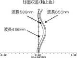
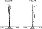
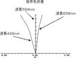
実施例1の撮像レンズLAの球面収差(軸上色収差)を図3に、非点収差及び歪曲収差を図4に、倍率色収差を図5に示す。なお、各図の収差は、波長486nm、波長588nm、波長656nmの3波長におけるそれぞれの収差の結果である。又、非点収差のSはサジタル像面に対する収差、Tはタンジェンシャル像面に対する収差である。以上の結果より、実施例1の撮像レンズLAは、小型で、良好な光学特性を有している。 FIG. 3 shows spherical aberration (axial chromatic aberration) of the imaging lens LA of Example 1, FIG. 4 shows astigmatism and distortion, and FIG. 5 shows lateral chromatic aberration. In addition, the aberration of each figure is a result of each aberration in three wavelengths, wavelength 486nm, wavelength 588nm, and wavelength 656nm. Further, astigmatism S is an aberration with respect to the sagittal image surface, and T is an aberration with respect to the tangential image surface. From the above results, the imaging lens LA of Example 1 is small and has good optical characteristics.
(実施例2)
図6は、実施例2の撮像レンズLAの配置を示す構成図である。実施例2の撮像レンズLAを構成する第1レンズL1及び第2レンズL2のそれぞれの物体側面及び像面側面の曲率半径R、レンズの中心厚あるいはレンズ間距離d、屈折率nd、アッベ数νdを表3に、円錐係数k、非球面係数の値を表4に示す。(Example 2)
FIG. 6 is a configuration diagram illustrating the arrangement of the imaging lens LA according to the second embodiment. The curvature radius R of the object side surface and the image surface side surface of each of the first lens L1 and the second lens L2 constituting the imaging lens LA of Example 2, the lens center thickness or the inter-lens distance d, the refractive index nd, and the Abbe number νd. Table 3 shows the values of the conical coefficient k and the aspheric coefficient.
実施例2の撮像レンズLAは、表9に示すように条件式(1)〜(4)を満足し、撮像レンズLA全体の焦点距離f、光学長TTLは短い。 The imaging lens LA of Example 2 satisfies the conditional expressions (1) to (4) as shown in Table 9, and the focal length f and the optical length TTL of the entire imaging lens LA are short.
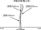
実施例2の撮像レンズLAの球面収差(軸上色収差)を図7に、非点収差及び歪曲収差を図8に、倍率色収差を図9に示す。なお、各図の収差は、波長486nm、波長588nm、波長656nmの3波長におけるそれぞれの収差の結果である。又、非点収差のSはサジタル像面に対する収差、Tはタンジェンシャル像面に対する収差である。以上の結果より、実施例2の撮像レンズLAは、小型で、良好な光学特性を有している。 FIG. 7 shows spherical aberration (axial chromatic aberration) of the imaging lens LA of Example 2, FIG. 8 shows astigmatism and distortion, and FIG. 9 shows lateral chromatic aberration. In addition, the aberration of each figure is a result of each aberration in three wavelengths, wavelength 486nm, wavelength 588nm, and wavelength 656nm. Further, astigmatism S is an aberration with respect to the sagittal image surface, and T is an aberration with respect to the tangential image surface. From the above results, the imaging lens LA of Example 2 is small and has good optical characteristics.
(実施例3)
図10は、実施例3の撮像レンズLAの配置を示す構成図である。実施例3の撮像レンズLAを構成する第1レンズL1及び第2レンズL2のそれぞれの物体側面及び像面側面の曲率半径R、レンズの中心厚あるいはレンズ間距離d、屈折率nd、アッベ数νdを表5に、円錐係数k、非球面係数の値を表6に示す。(Example 3)
FIG. 10 is a configuration diagram illustrating an arrangement of the imaging lens LA according to the third embodiment. The curvature radius R of the object side surface and the image surface side surface of each of the first lens L1 and the second lens L2 constituting the imaging lens LA of Embodiment 3, the lens center thickness or the inter-lens distance d, the refractive index nd, and the Abbe number νd. Table 5 shows the values of the conical coefficient k and the aspheric coefficient.
実施例3の撮像レンズLAは、表9に示すように条件式(1)〜(4)を満足し、撮像レンズLA全体の焦点距離f、光学長TTLは短い。 The imaging lens LA of Example 3 satisfies the conditional expressions (1) to (4) as shown in Table 9, and the focal length f and the optical length TTL of the entire imaging lens LA are short.
実施例3の撮像レンズLAの球面収差(軸上色収差)を図11に、非点収差及び歪曲収差を図12に、倍率色収差を図13に示す。なお、各図の収差は、波長486nm、波長588nm、波長656nmの3波長におけるそれぞれの収差の結果である。又、非点収差のSはサジタル像面に対する収差、Tはタンジェンシャル像面に対する収差である。以上の結果より、実施例3の撮像レンズLAは、小型で、良好な光学特性を有している。 FIG. 11 shows spherical aberration (axial chromatic aberration) of the imaging lens LA of Example 3, FIG. 12 shows astigmatism and distortion, and FIG. 13 shows lateral chromatic aberration. In addition, the aberration of each figure is a result of each aberration in three wavelengths, wavelength 486nm, wavelength 588nm, and wavelength 656nm. Further, astigmatism S is an aberration with respect to the sagittal image surface, and T is an aberration with respect to the tangential image surface. From the above results, the imaging lens LA of Example 3 is small and has good optical characteristics.
(実施例4)
図14は、実施例4の撮像レンズLAの配置を示す構成図である。実施例4の撮像レンズLAを構成する第1レンズL1及び第2レンズL2のそれぞれの物体側面及び像面側面の曲率半径R、レンズの中心厚あるいはレンズ間距離d、屈折率nd、アッベ数νdを表7に、円錐係数k、非球面係数の値を表8に示す。Example 4
FIG. 14 is a configuration diagram illustrating the arrangement of the imaging lens LA according to the fourth embodiment. The curvature radius R of the object side surface and the image surface side surface of each of the first lens L1 and the second lens L2 constituting the imaging lens LA of Example 4, the lens center thickness or inter-lens distance d, the refractive index nd, and the Abbe number νd Table 7 shows the conic coefficient k and aspheric coefficient values.
実施例4の撮像レンズLAは、表9に示すように条件式(1)〜(4)を満足し、撮像レンズLA全体の焦点距離f、光学長TTLは短い。 The imaging lens LA of Example 4 satisfies the conditional expressions (1) to (4) as shown in Table 9, and the focal length f and the optical length TTL of the entire imaging lens LA are short.
実施例4の撮像レンズLAの球面収差(軸上色収差)を図15に、非点収差及び歪曲収差を図16に、倍率色収差を図17に示す。なお、各図の収差は、波長486nm、波長588nm、波長656nmの3波長におけるそれぞれの収差の結果である。又、非点収差のSはサジタル像面に対する収差、Tはタンジェンシャル像面に対する収差である。以上の結果より、実施例4の撮像レンズLAは、小型で、良好な光学特性を有している。 FIG. 15 shows spherical aberration (axial chromatic aberration) of the imaging lens LA of Example 4, FIG. 16 shows astigmatism and distortion, and FIG. 17 shows lateral chromatic aberration. In addition, the aberration of each figure is a result of each aberration in three wavelengths, wavelength 486nm, wavelength 588nm, and wavelength 656nm. Further, astigmatism S is an aberration with respect to the sagittal image surface, and T is an aberration with respect to the tangential image surface. From the above results, the imaging lens LA of Example 4 is small and has good optical characteristics.
表9に各数値実施例の諸値及び条件式(1)〜(4)で規定したパラメーターに対応する値を示す。尚、表9に示す諸値単位は、f(mm)、f1(mm)、f2(mm)、TTL(mm)である。 Table 9 shows values corresponding to the parameters defined in the numerical values and conditional expressions (1) to (4) of each numerical example. The units of values shown in Table 9 are f (mm), f1 (mm), f2 (mm), and TTL (mm).
LA :撮像レンズ
S1 :絞り
L1 :第1レンズ
L2 :第2レンズ
GF :ガラス平板
R1 :第1レンズL1の物体側の面の曲率半径
R2 :第1レンズL1の像面側の面の曲率半径
R3 :第2レンズL2の物体側の面の曲率半径
R4 :第2レンズL2の像面側の面の曲率半径
R5 :ガラス平板GFの物体側の面
R6 :ガラス平板GFの像面側の面
d1 :第1レンズL1の中心厚
d2 :第1レンズL1の像面側面と第2レンズL2の物体側面との間の距離
d3 :第2レンズL2の中心厚
d4 :第2レンズL2の像面側面とガラス平板GFの物体側面との間の距離
d5 :ガラス平板GFの中心厚LA: Imaging lens S1: Diaphragm L1: First lens L2: Second lens GF: Glass flat plate R1: Curvature radius of the object side surface of the first lens L1 R2: Curvature radius of the image side surface of the first lens L1 R3: radius of curvature of the object side surface of the second lens L2 R4: radius of curvature of the image side surface of the second lens L2 R5: object side surface R6 of the glass plate GF: image side surface of the glass plate GF d1: Center thickness of the first lens L1 d2: Distance between the image surface side surface of the first lens L1 and the object side surface of the second lens L2 d3: Center thickness of the second lens L2 d4: Image surface of the second lens L2 Distance d5 between side surface and object side surface of glass flat plate GF: center thickness of glass flat plate GF
Claims (3)
Translated fromJapanese0.50<R1/R2<0.65 (1)
0.30<d3/f<0.50 (2)
但し、
R1:第1レンズの物体側の面の曲率半径
R2:第1レンズの像面側の面の曲率半径
d3:第2レンズの中心厚
f:撮像レンズ全体の焦点距離
である。
In order from the object to the image surface side, a stop, a meniscus first lens having a positive power with the convex surface facing the object side, and a second lens having a positive power with the convex surface facing the image surface side are arranged. An imaging lens that satisfies the following conditional expressions (1) and (2):
0.50 <R1 / R2 <0.65 (1)
0.30 <d3 / f <0.50 (2)
However,
R1: radius of curvature of the object side surface of the first lens R2: radius of curvature of the image side surface of the first lens d3: center thickness of the second lens f: focal length of the entire imaging lens.
0.60<d1/d2<1.80 (3)
0.40<d1/d3<0.85 (4)
但し、
d1:第1レンズの中心厚
d2:第1レンズの像面側の面と第2レンズの物体側の面との間の距離
d3:第2レンズの中心厚
である。The imaging lens according to claim 1, wherein the following conditional expressions (3) and (4) are satisfied.
0.60 <d1 / d2 <1.80 (3)
0.40 <d1 / d3 <0.85 (4)
However,
d1: Center thickness of the first lens d2: Distance between the image side surface of the first lens and the object side surface of the second lens d3: Center thickness of the second lens.
Priority Applications (2)
| Application Number | Priority Date | Filing Date | Title |
|---|---|---|---|
| JP2008008130AJP4174553B1 (en) | 2008-01-17 | 2008-01-17 | Imaging lens |
| US12/342,326US7852573B2 (en) | 2008-01-17 | 2008-12-23 | Image taking lens |
Applications Claiming Priority (1)
| Application Number | Priority Date | Filing Date | Title |
|---|---|---|---|
| JP2008008130AJP4174553B1 (en) | 2008-01-17 | 2008-01-17 | Imaging lens |
Publications (2)
| Publication Number | Publication Date |
|---|---|
| JP4174553B1true JP4174553B1 (en) | 2008-11-05 |
| JP2009169165A JP2009169165A (en) | 2009-07-30 |
Family
ID=40056050
Family Applications (1)
| Application Number | Title | Priority Date | Filing Date |
|---|---|---|---|
| JP2008008130AExpired - Fee RelatedJP4174553B1 (en) | 2008-01-17 | 2008-01-17 | Imaging lens |
Country Status (2)
| Country | Link |
|---|---|
| US (1) | US7852573B2 (en) |
| JP (1) | JP4174553B1 (en) |
Families Citing this family (11)
| Publication number | Priority date | Publication date | Assignee | Title |
|---|---|---|---|---|
| JP4902700B2 (en)* | 2009-07-14 | 2012-03-21 | シャープ株式会社 | Imaging module |
| JP5059065B2 (en)* | 2009-08-07 | 2012-10-24 | シャープ株式会社 | Imaging module, imaging lens, and code reading method |
| JP4886016B2 (en)* | 2009-10-08 | 2012-02-29 | シャープ株式会社 | Imaging lens, imaging module, imaging lens manufacturing method, and imaging module manufacturing method |
| JP4943518B2 (en)* | 2010-01-14 | 2012-05-30 | シャープ株式会社 | Imaging lens, imaging module, and portable information device |
| JP5043146B2 (en) | 2010-04-12 | 2012-10-10 | シャープ株式会社 | Imaging lens and imaging module |
| WO2012100405A1 (en)* | 2011-01-24 | 2012-08-02 | Ether Precision, Inc. | Two lens module including a plano-convex lens |
| JP2012220590A (en) | 2011-04-05 | 2012-11-12 | Sharp Corp | Imaging lens and imaging module |
| US8385007B2 (en)* | 2011-05-03 | 2013-02-26 | Himax Technologies Limited | Micro-lens module |
| CN108873261B (en)* | 2018-08-02 | 2021-01-22 | 诚瑞光学(苏州)有限公司 | Image pickup optical lens |
| CN110251049B (en)* | 2019-06-14 | 2021-05-04 | 江西联创电子有限公司 | Endoscope lens |
| CN113009675B (en)* | 2021-03-24 | 2022-05-13 | 天津欧菲光电有限公司 | Optical system, image capturing module and electronic equipment |
Family Cites Families (5)
| Publication number | Priority date | Publication date | Assignee | Title |
|---|---|---|---|---|
| JP3822268B2 (en)* | 1995-08-24 | 2006-09-13 | オリンパス株式会社 | Zoom lens |
| JP4442184B2 (en) | 2003-10-14 | 2010-03-31 | コニカミノルタビジネステクノロジーズ株式会社 | Imaging lens |
| JP3753183B1 (en) | 2004-10-19 | 2006-03-08 | 株式会社エンプラス | Imaging lens |
| JP4914136B2 (en)* | 2005-09-06 | 2012-04-11 | キヤノン株式会社 | Zoom lens and imaging apparatus having the same |
| KR100703210B1 (en)* | 2005-11-25 | 2007-04-06 | 삼성전기주식회사 | Ultra compact imaging optics |
- 2008
- 2008-01-17JPJP2008008130Apatent/JP4174553B1/ennot_activeExpired - Fee Related
- 2008-12-23USUS12/342,326patent/US7852573B2/ennot_activeExpired - Fee Related
Also Published As
| Publication number | Publication date |
|---|---|
| US7852573B2 (en) | 2010-12-14 |
| US20090185294A1 (en) | 2009-07-23 |
| JP2009169165A (en) | 2009-07-30 |
Similar Documents
| Publication | Publication Date | Title |
|---|---|---|
| JP4071819B1 (en) | Imaging lens | |
| JP4174553B1 (en) | Imaging lens | |
| JP4418844B2 (en) | Imaging lens | |
| JP4887507B1 (en) | Imaging lens | |
| JP5513641B1 (en) | Imaging lens | |
| JP4361120B2 (en) | Imaging lens | |
| JP4781487B1 (en) | Imaging lens | |
| JP4792542B1 (en) | Imaging lens | |
| JP4071817B1 (en) | Imaging lens | |
| JP4222623B1 (en) | Imaging lens | |
| JP2008292651A (en) | Imaging lens | |
| JP4064434B1 (en) | Imaging lens | |
| JP2009103897A (en) | Imaging lens | |
| JP2009103896A (en) | Imaging lens | |
| JP4256443B1 (en) | Imaging lens | |
| TWI440880B (en) | Camera lens | |
| JP2008158122A (en) | Imaging lens | |
| JP2008203307A (en) | Imaging lens | |
| JP2009098183A (en) | Imaging lens | |
| JP4256442B1 (en) | Imaging lens | |
| JP4548861B1 (en) | Imaging lens | |
| JP4376954B1 (en) | Imaging lens | |
| JP4145952B1 (en) | Imaging lens | |
| JP2009116063A (en) | Imaging lens | |
| JP4121546B1 (en) | Imaging lens |
Legal Events
| Date | Code | Title | Description |
|---|---|---|---|
| TRDD | Decision of grant or rejection written | ||
| A01 | Written decision to grant a patent or to grant a registration (utility model) | Free format text:JAPANESE INTERMEDIATE CODE: A01 Effective date:20080805 | |
| A01 | Written decision to grant a patent or to grant a registration (utility model) | Free format text:JAPANESE INTERMEDIATE CODE: A01 | |
| A61 | First payment of annual fees (during grant procedure) | Free format text:JAPANESE INTERMEDIATE CODE: A61 Effective date:20080818 | |
| R150 | Certificate of patent or registration of utility model | Free format text:JAPANESE INTERMEDIATE CODE: R150 | |
| FPAY | Renewal fee payment (event date is renewal date of database) | Free format text:PAYMENT UNTIL: 20110822 Year of fee payment:3 | |
| FPAY | Renewal fee payment (event date is renewal date of database) | Free format text:PAYMENT UNTIL: 20110822 Year of fee payment:3 | |
| FPAY | Renewal fee payment (event date is renewal date of database) | Free format text:PAYMENT UNTIL: 20120822 Year of fee payment:4 | |
| LAPS | Cancellation because of no payment of annual fees |