JP4173737B2 - Counter balance mechanism and pan / tilt head - Google Patents
Counter balance mechanism and pan / tilt headDownload PDFInfo
- Publication number
- JP4173737B2 JP4173737B2JP2002564294AJP2002564294AJP4173737B2JP 4173737 B2JP4173737 B2JP 4173737B2JP 2002564294 AJP2002564294 AJP 2002564294AJP 2002564294 AJP2002564294 AJP 2002564294AJP 4173737 B2JP4173737 B2JP 4173737B2
- Authority
- JP
- Japan
- Prior art keywords
- cam
- support
- mechanism according
- counterbalance mechanism
- axis
- Prior art date
- Legal status (The legal status is an assumption and is not a legal conclusion. Google has not performed a legal analysis and makes no representation as to the accuracy of the status listed.)
- Expired - Fee Related
Links
- 230000007246mechanismEffects0.000titleclaimsdescription32
- 230000006835compressionEffects0.000claimsdescription4
- 238000007906compressionMethods0.000claimsdescription4
- 230000005484gravityEffects0.000description6
- 230000000694effectsEffects0.000description5
- 230000007423decreaseEffects0.000description3
- 239000012530fluidSubstances0.000description2
- 238000004364calculation methodMethods0.000description1
- 238000010276constructionMethods0.000description1
- 238000012886linear functionMethods0.000description1
- 238000000034methodMethods0.000description1
- 230000036316preloadEffects0.000description1
- 239000007787solidSubstances0.000description1
- 230000000087stabilizing effectEffects0.000description1
Images


Classifications
- F—MECHANICAL ENGINEERING; LIGHTING; HEATING; WEAPONS; BLASTING
- F16—ENGINEERING ELEMENTS AND UNITS; GENERAL MEASURES FOR PRODUCING AND MAINTAINING EFFECTIVE FUNCTIONING OF MACHINES OR INSTALLATIONS; THERMAL INSULATION IN GENERAL
- F16M—FRAMES, CASINGS OR BEDS OF ENGINES, MACHINES OR APPARATUS, NOT SPECIFIC TO ENGINES, MACHINES OR APPARATUS PROVIDED FOR ELSEWHERE; STANDS; SUPPORTS
- F16M11/00—Stands or trestles as supports for apparatus or articles placed thereon ; Stands for scientific apparatus such as gravitational force meters
- F16M11/02—Heads
- F16M11/04—Means for attachment of apparatus; Means allowing adjustment of the apparatus relatively to the stand
- F16M11/06—Means for attachment of apparatus; Means allowing adjustment of the apparatus relatively to the stand allowing pivoting
- F16M11/10—Means for attachment of apparatus; Means allowing adjustment of the apparatus relatively to the stand allowing pivoting around a horizontal axis
- F—MECHANICAL ENGINEERING; LIGHTING; HEATING; WEAPONS; BLASTING
- F16—ENGINEERING ELEMENTS AND UNITS; GENERAL MEASURES FOR PRODUCING AND MAINTAINING EFFECTIVE FUNCTIONING OF MACHINES OR INSTALLATIONS; THERMAL INSULATION IN GENERAL
- F16F—SPRINGS; SHOCK-ABSORBERS; MEANS FOR DAMPING VIBRATION
- F16F15/00—Suppression of vibrations in systems; Means or arrangements for avoiding or reducing out-of-balance forces, e.g. due to motion
- F16F15/28—Counterweights, i.e. additional weights counterbalancing inertia forces induced by the reciprocating movement of masses in the system, e.g. of pistons attached to an engine crankshaft; Attaching or mounting same
- F—MECHANICAL ENGINEERING; LIGHTING; HEATING; WEAPONS; BLASTING
- F16—ENGINEERING ELEMENTS AND UNITS; GENERAL MEASURES FOR PRODUCING AND MAINTAINING EFFECTIVE FUNCTIONING OF MACHINES OR INSTALLATIONS; THERMAL INSULATION IN GENERAL
- F16M—FRAMES, CASINGS OR BEDS OF ENGINES, MACHINES OR APPARATUS, NOT SPECIFIC TO ENGINES, MACHINES OR APPARATUS PROVIDED FOR ELSEWHERE; STANDS; SUPPORTS
- F16M2200/00—Details of stands or supports
- F16M2200/04—Balancing means
- F16M2200/041—Balancing means for balancing rotational movement of the head
Landscapes
- Engineering & Computer Science (AREA)
- General Engineering & Computer Science (AREA)
- Mechanical Engineering (AREA)
- Physics & Mathematics (AREA)
- Acoustics & Sound (AREA)
- Aviation & Aerospace Engineering (AREA)
- Accessories Of Cameras (AREA)
- Transmission Devices (AREA)
- Vehicle Step Arrangements And Article Storage (AREA)
- Manipulator (AREA)
Description
Translated fromJapanese本発明は、カウンターバランス機構に関する。特に、三脚に取り付けられると共に、水平軸の周囲でチルト可能なカメラや他の機器を支持するための、流体(油圧)式ヘッド(fluid head)等のパン/チルトヘッドの一部を構成するカウンターバランス機構に関するが、これに限定されない。 The present invention relates to a counterbalance mechanism. In particular, a counter that is attached to a tripod and forms part of a pan / tilt head such as a fluid (hydraulic) head for supporting a camera or other device that can be tilted around a horizontal axis. Although it is related with a balance mechanism, it is not limited to this.
カメラ装置を水平軸の周囲の任意の所望の角度でバランスさせて保持可能なヘッドを用いて、カメラ装置を水平軸の周囲でチルトさせる必要がしばしばある。カメラを所望の角度にセットしてからヘッドをその角度に固定するという、手動の機構を用いることもできるが、これは業務目的では不十分で煩わしく、さほど実用的ではない。 It is often necessary to tilt the camera device about the horizontal axis using a head that can hold the camera device balanced at any desired angle about the horizontal axis. A manual mechanism can be used in which the camera is set at a desired angle and then the head is fixed at that angle, but this is insufficient and cumbersome for business purposes and is not very practical.
過去に多くのカウンターバランス機構が提案されているが、今日まで、実質的に任意の所望の角度の荷重(例えばカメラでは、約50キログラムまでのかなりの荷重となり得る)に対して効果的に釣り合いをとるカウンターバランス機構を得ることは、非常に困難であると認められている。図1を参照すると、荷重Lのカメラが水平軸Aの周囲を所望の角度だけ回転させられる場合、任意の角度におけるトルクは、荷重L×軸から荷重までの水平距離Lに等しく、これは、垂直からの角度が増加するにつれ、概ね正弦曲線を描いて増加する。カウンターバランス機構はこれを打ち消すことが要求されるが、これは線形関数ではないので、許容可能なサイズ/質量の組み合わせの範囲内で達成するのは困難である。 Many counterbalance mechanisms have been proposed in the past, but to date, they are effectively balanced against virtually any desired angular load (for example, a camera can be a significant load up to about 50 kilograms). It is recognized that it is very difficult to obtain a counterbalance mechanism that takes Referring to FIG. 1, if a camera with a load L is rotated around the horizontal axis A by a desired angle, the torque at any angle is equal to the load L × the horizontal distance L from the axis to the load, which is As the angle from vertical increases, it generally increases in a sinusoidal manner. Counterbalance mechanisms are required to counteract this, but since this is not a linear function, it is difficult to achieve within an acceptable size / mass combination.
更に、第一に、支持体上に配置されて傾けられる品物の様々な重量に対して、第二に、品物の様々な重心位置(例えば、三脚に取り付けられたカメラの重心は、三脚の中心の直上に取り付けられた場合の点と一致しない場合がある)に対して、許容誤差を設けなければならない。 In addition, first, for different weights of items placed and tilted on the support, secondly, different center of gravity positions of the items (for example, the center of gravity of the camera attached to the tripod is the center of the tripod) For some cases, it may not match the point when it is mounted directly above.
本発明は、改良されたカウンターバランス機構を提供する試みにおいて生まれたものである。 The present invention was born in an attempt to provide an improved counterbalance mechanism.
第1の態様の本発明によれば、水平軸の周囲でチルトされる(傾けられる)品物を支持する支持体と、前記支持体の回転面に対して垂直な方向に変化するカム面を有する、前記支持体と共に可動なカムと、弾性手段によって付勢されたカム従動子であって、前記支持体が回転すると、前記カム従動子及び前記弾性手段が、前記支持体の回転によって生じるトルクを実質的に打ち消すように及ぼされる戻り力を生じる、カム従動子と、を含む、カウンターバランス機構が提供される。 According to the first aspect of the present invention, there is provided a support body that supports an article tilted (tilted) around a horizontal axis, and a cam surface that changes in a direction perpendicular to the rotation surface of the support body. A cam movable together with the support and a cam follower biased by elastic means, and when the support rotates, the cam follower and the elastic means generate torque generated by the rotation of the support. A counterbalance mechanism is provided that includes a cam follower that produces a return force exerted to substantially cancel.
前記弾性手段は1つ以上のばねであるのが好ましい。 The elastic means is preferably one or more springs.
好ましくは、前記支持体上の荷重に従って前記戻り力を変化させる手段が設けられ、前記カム及び前記弾性手段が、前記支持体が回転する中心軸からオフセットされた中心周りに回転可能であり、特定の角度にわたる前記支持体の回転に起因して及ぼされる前記戻り力を変化させるために、前記カム従動子の力が反作用する点である可変反作用点を設定する手段を含む。Preferably, a means for changing the return force according to a load on the support is provided, and the cam and the elastic means are rotatable around a center offset from a central axis around which the support rotates. Means for setting a variable reaction point, which is the point at which the force of thecam follower reacts to change the return force exerted due to rotation of the support over an angle of.
本発明によれば、更に、本明細書で説明する新規な特徴の任意の1つ以上を有するカウンターバランス機構又はチルトヘッドが提供される。 The present invention further provides a counterbalance mechanism or tilt head having any one or more of the novel features described herein.
次に、添付の図面を参照し、本発明の実施形態を単に例として説明する。 Embodiments of the present invention will now be described by way of example only with reference to the accompanying drawings.
上述したように、図1a及び図1bを参照すると、プラットフォーム上の荷重が軸の周囲で傾けられると、この荷重は可変のトルクを加える。本発明は、任意の所望の傾斜角度においてこの影響に対する釣り合いをとることが可能な、カメラや他の視聴覚機器用のチルト/パンヘッド等の、チルト可能プラットフォーム用の機構を提供する試みにおいて生まれたものである。 As described above, with reference to FIGS. 1a and 1b, when the load on the platform is tilted around the axis, this load applies a variable torque. The present invention was born in an attempt to provide a mechanism for a tiltable platform, such as a tilt / pan head for cameras and other audiovisual equipment, that can balance this effect at any desired tilt angle. Is.
図2を参照すると、チルト/パンヘッドはプラットフォーム1を有し、その上に、カメラ等の支持される装置を取り付けることができる。プラットフォーム1は、離間された2つの長方形の板2、3の上に取り付けられている。板3は、図7に詳細に示されており、板2も同様である。図2及び図3に示されるように、板2には、一方の面から他方の板に向かって延出して概ね環状の軸方向の突起を形成するカム4が設けられている。カムは板と一体であってもよく、又は、板に取り付けられてもよい。カムの高さは、カムの周囲で半径方向に変化する。板2は、水平軸の周囲で、流体が充填された概ね円柱形の本体5に対して相対的に回転可能に取り付けられる。相対回転は、これらの間のベアリング(明確化のために図示せず)の周囲で生じる。同様に、板3は、円柱形の本体6及びハブ22に対して相対的に回転し、ここでもベアリングが設けられている。本体5及び6は共通構造7に接続されており、共通構造7は、三脚又は他の安定構造に取り付けられるか、又は実際にその一部を構成することもあり、その上にヘッドを取り付けることができる。ヘッドがチルト及びパンヘッドである場合には、この構造7は、水平及び垂直平面の両方における回転が達成されるように、垂直軸周りに回転するよう構成されてもよい。通常はこの範囲又は回転が望ましい。 Referring to FIG. 2, the tilt / pan head has a platform 1 on which a supported device such as a camera can be mounted. The platform 1 is mounted on two
更なる円柱形の本体(又はドラム)8は、カム4によって定められる環状領域内に位置することが可能なサイズであり、その側面にカム従動子9を有する。これは、一般的に、本体8の外面から延出するスタッド、ピン又は突起10と、ピンと同軸であってピンに対して自由に回転するよう構成された環状リング11とを有し、リングはカム4の上面に対してスライド可能である。 The further cylindrical body (or drum) 8 is sized to be located in an annular region defined by the
本体8は、ハブ22に最も近い本体表面に開口した複数のボアホール14が設けられている以外は、概ね中実である。各ボアホールに1つずつの複数のばね12が取り付けられており、これらの他端部は、ハブ22に取り付けられるか、又は単にハブ22によって支持されている。板3は、これに対して相対回転する。他のタイプの弾性手段を設けてもよいが、これらはばねであるのが好ましく、予め応力が与えられているのが好ましい。一実施形態では、各ばねのレーティング(rating)が約9.72N/mmである20個のばねが設けられるが、これに限定されない。 The
部材8のボアは、単にばねの場所を設けるためのものであり、その代わりに、ばねは、単に、円柱形の本体8の一端部に接触するよう取り付けられてもよい。 The bore of the
使用に際しては、ヘッドアセンブリ13は、三脚又は他の安定構造の上に配置され、チルトされるカメラ又は他の装置は、適切な手段によってプラットフォーム1に固定される。装置がチルトされる際には、カム4も回転する。ばね12によってカム従動子がカムに対して押しつけられるので、カム従動子は、カムの作用による動きの縦方向(longitudinal)の成分で移動する。これにより、ばね12の圧縮の程度が増加又は減少し、ハブ22が、本体8に対する等しく且つ逆向きの戻り力を生じるので、カム従動子9が、より大きな又は小さな戻り力をカム4に及ぼす。図5に模式的に示されるように、カムの面に対して垂直ではない方向の戻り力Fは、力Fに対して90°の成分を有する力も生じ、これは、カム4の動きに抵抗するよう作用する。カムが縦方向に前後に移動するにつれて、ばねにかかる戻り力が変化すると、この抵抗力が変化し、これは、傾いた荷重の可変のトルクに対して釣り合いをとるよう作用する。 In use, the
プラットフォームが回転する際のトルクの変化は線形ではないので、カムの形状は、この非線形を考慮しなければならない。高さ及び回転の度合いに関するカムのプロファイル(形状)は、次の項目を考慮しなければならない。
(a)中心から外れる荷重によって与えられるモーメント
(b)荷重が軸周りに回動することに起因するレバー(てこ)の実効長さの変化
(c)カムの高さによって与えられる圧縮に起因するばねエネルギー
(d)カムの勾配Since the change in torque as the platform rotates is not linear, the cam shape must take this nonlinearity into account. The cam profile (shape) with respect to height and degree of rotation must consider the following items:
(A) Moment given by load deviating from center (b) Change in effective length of lever (lever) caused by load turning around axis (c) Resulting from compression given by cam height Spring energy (d) Cam slope
ばねエネルギーは、予荷重と、カムの高さによって与えられる追加の圧縮とに依存する。尚、カムの高さ及び勾配は相互作用する。プロファイルは、例えば10分の1度以内までのカム上の各点について計算されるのが好ましいが、他の(例えば、より大きな)増分で与えられてもよく、又は、コンピュータ支援機械で製造される場合には式によって与えられてもよく、これは当業者によって実行可能である。一例では、特定の荷重について、荷重の重心の軸が、傾いた装置の中心軸と一致すると仮定すると、1組のカム及びカムの上昇角度(cam rise angles)は、カムの角度と共に、次のように変化する。
これは、有効搭載量が40kg、荷重半径が250mm、各々のレーティングが9.72N/mmで自由長さが89.9mmで最小長さが44.27mmの20個のばねを使用した場合である。 This is the case when 20 springs having an effective load of 40 kg, a load radius of 250 mm, a rating of 9.72 N / mm, a free length of 89.9 mm and a minimum length of 44.27 mm are used. .
カム従動子がカムの周囲を移動するために、本発明の一実施形態では、カム従動子は拘束され、カムがカム従動子に対して相対的に回転する。 In order to move the cam follower around the cam, in one embodiment of the present invention, the cam follower is constrained and the cam rotates relative to the cam follower.
図2には1つの従動子が示されているが、良好な実施と調和するよう、軸回りの力の釣り合いをとるためには、複数の等間隔の従動子が非常に望ましく、一般的に用いられる。 Although a single follower is shown in FIG. 2, a plurality of equally spaced followers are highly desirable and generally used to balance the forces around the axis to harmonize with good practice. Used.
本体8及び22は、ねじれ方向には互いに関して剛性でありつつ、軸方向には相対移動可能である必要がある。これは、キーやスプライン等の多くの手段によって達成できる。しかし、有害なバックラッシュ又は軸摩擦を回避するために、コーダル接続(chordal link)又は次の方法のいずれかを用いてもよい。この好ましい実施形態では、カム従動子本体8に更に1対の突起20、21(図4)が設けられており、使用に際しては、これらがハブ22の周軸方向突起22bに当たる。カム従動子10の軸方向の移動を妨げないために、ハブ22にはカットアウト22aが必要な場合もある。要素20及び21は、これら及び本体8がハブ22に対して縦方向にスライド可能なように、本体8からの突起及び回転可能なディスクを有するカム従動子と類似の構成であってもよい。力の釣り合いのために好ましいように、1つ以上の突起を設ける場合には、同数の関連づけられた要素20及び21の対(カム従動子)を等間隔で設けてもよい。 The
上記の実施形態では、カムのプロファイル及び/又はばねのレーティングは、特定の重量の荷重に対して選択され、荷重の傾きに対して釣り合いをとるために等価且つ逆向きの戻り力を与えるために、荷重は、その重心が支持機構に対して特定の位置になるよう取り付けられる。実際には、異なる重量、又は、装置の中心には存在しないかもしれない様々な重心の荷重に対応できるのが望ましい。従って、本発明の好ましい実施形態では、この適応性を提供するための機構が含まれる。 In the above embodiment, the cam profile and / or the spring rating is selected for a specific weight load to provide an equivalent and reverse return force to balance the load slope. The load is attached so that its center of gravity is at a specific position with respect to the support mechanism. In practice, it is desirable to be able to accommodate different weights or loads of various centers of gravity that may not exist at the center of the device. Accordingly, a preferred embodiment of the present invention includes a mechanism for providing this flexibility.
図4は、「エネルギーパック」40と呼んでもよい装置の部品を示す。これは、従動子10、20、21を有するドラム8と、ハブ22と、板22、26を貫通して板2の中へと延びる軸23を有するレバー27とを含む。従って、「エネルギーパック」は、プラットフォームの回転軸Oからオフセットした軸周りに回転可能である。軸23は、ハブ22の中心穴のキー溝25に嵌るキー20(図7)を有するので、ハブ22(並びに、カム従動子及びばね)は、軸23と共に回転する。カムも、板の2の中心からオフセットして取り付けられているので、カム及び弾性手段の回転軸は、支持体(ベアリング26と同軸)の回転軸からオフセットしている。 FIG. 4 shows the parts of the device that may be referred to as an “energy pack” 40. This includes a
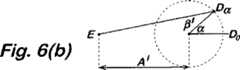
図6(a)及び図6(b)はこの効果を示す。図6(a)では、点Oはチルト回転の中心であり、Dはエネルギーパックの中心であり、Eはエネルギーパックの反作用点である。以下に、これを達成する機構を更に説明する。荷重の質量はKであり、チルト回転の中心Oから、αによって与えられると共にαと比例する距離Mだけ離れた点Gで、重心が作用するよう配置されている。 6 (a) and 6 (b) show this effect. In FIG. 6A, point O is the center of tilt rotation, D is the center of the energy pack, and E is the reaction point of the energy pack. The mechanism for achieving this will be further described below. The mass of the load is K, and it is arranged so that the center of gravity acts at a point G which is given by α and is separated from the center O of the tilt rotation by a distance M which is proportional to α.
荷重が角度αだけチルトされると、カム従動子は、反作用点Eによって制約されることにより、カムの周囲を角度β°だけ回転する。このカム/ばね構成は、±90°の間の任意の角度αにおける負荷のトルクKMに等しく且つ逆方向の作用を与えるように設計されている。上述したように、これは、荷重及び半径OGが一定であれば正確に計算可能である。荷重K又は半径OG(及びそれに従ってM)の変化に対応するために、距離Aを調整してもよい。即ち、反作用点の位置を調整してもよい。モーメントKMが減少すると、Aも低減される必要があり、これによって、カム周囲の従動子の回転Bが減少することにより、反作用が減少する。これは図6(b)に示されており、ここでは、点Eは、チルト回転の中心Oからの距離がA’となるよう移動されている。 When the load is tilted by the angle α, the cam follower is constrained by the reaction point E and rotates around the cam by an angle β °. This cam / spring configuration is designed to provide an equal and opposite effect on the load torque KM at any angle α between ± 90 °. As mentioned above, this can be calculated accurately if the load and radius OG are constant. The distance A may be adjusted to accommodate changes in load K or radius OG (and M accordingly). That is, the position of the reaction point may be adjusted. As the moment KM decreases, A also needs to be reduced, thereby reducing the reaction by reducing the rotation B of the follower around the cam. This is shown in FIG. 6B, where the point E is moved so that the distance from the center O of the tilt rotation is A '.
図6(a)と図6(b)との比較からわかるように、角度αが同じ場合、距離AがAからA’に減少すると、角度βもβからβ’に変化する。この実際の効果は、カムの異なる部分がカム従動子に作用するので、同じチルト角度に対して、異なる戻り力、及びそれに従って釣り合いをとる力を及ぼすことである。従って、α°チルトされた軽い荷重は、カムの、異なる角度α±Δαにおいてより重い荷重が用いる部分を用いてもよい。例えば、60°チルトされた軽い荷重は、それより重い荷重が例えば30°で用いるカムの部分を用いてもよい。 As can be seen from the comparison between FIG. 6A and FIG. 6B, when the angle α is the same, when the distance A decreases from A to A ′, the angle β also changes from β to β ′. The actual effect is that different parts of the cam act on the cam follower, so that for the same tilt angle, different return forces and correspondingly balanced forces are exerted. Therefore, a light load tilted by α ° may use a portion of the cam that uses a heavier load at different angles α ± Δα. For example, a light load tilted by 60 ° may use a portion of a cam that uses a heavier load, for example, 30 °.
カムの計算は、距離Aが固定されている場合のαの変化に伴う長さEDの変化を考慮する必要がある。図7に示されるように、調整可能な反作用点Eは、板3(図2)内のほぼ中心にあるベアリング24を貫通するレバー23を設け、キー40及びキー溝25を介してハブ22を駆動することによって達成される。レバー23は、板6(図2)を貫通して延びており、その中心が、板3及び2の中心から軸がずれて取り付けられると共に、ベアリング26周りに回転可能である。レバーは、2つのアーム28及び29を有する概ねU型の部分27を有し、アーム28及び29の間には、アーム間の空隙内をスライド可能な可動キー30が保持される。板6内に固定された後部部材31には、スロット又は切取部32が設けられ、その中では、ピンがねじ山付きボルト34等に取り付けられ、本体31の中心から離れるよう及び中心に向かうよう、ボルトに対して相対移動する。これは、例えば、公知の機構によってピンをボルトに対して相対的に移動可能な簡単な回転つまみによって、板の他方の側から調節されるのが好ましい。エネルギーパックが反作用する点を調節するために、ピン33は適切な半径位置に移動され、これによりキー30がレバー23に対して相対的に移動される。この調節は、各異なる荷重で試行錯誤することによって実行可能であり、或いは、一旦荷重が既知になれば及び/又は中心からの荷重の質量のオフセットが既知になれば位置Eを設定可能なように、装置を較正できるのがより好ましい。 In the calculation of the cam, it is necessary to consider the change in the length ED accompanying the change in α when the distance A is fixed. As shown in FIG. 7, the adjustable reaction point E is provided with a
Claims (15)
Translated fromJapanese前記支持体の回転面に対して垂直な方向に変化するカム面を有する、前記支持体と共に可動な環状のカムと、
弾性手段によって付勢されたカム従動子であって、前記支持体が回転すると、前記カム従動子及び前記弾性手段が、前記支持体の回転によって生じるトルクを実質的に打ち消すように及ぼされる戻り力を生じる、カム従動子と、
を含むカウンターバランス機構であって、
前記支持体上の荷重に従って前記戻り力を変化させる手段が設けられ、
前記カムが、前記支持体の回転軸からオフセットした前記カム自体の軸周りに回転可能であり、
特定の角度にわたる前記支持体の回転に起因して及ぼされる前記戻り力を変化させるために、前記カム従動子の力が反作用する点である可変反作用点を設定する手段を含む、
カウンターバランス機構。A support for supporting an item tilted about a horizontal axis;
An annular cam movable with the support having a cam surface that changes in a direction perpendicular to the rotational surface of the support;
A cam follower biased by elastic means, and when the support rotates, the cam follower and the elastic means exert a return force exerted so as to substantially cancel the torque generated by the rotation of the support. A cam follower,
A counterbalance mechanism including
Means for changing the return force according to the load on the support is provided;
The cam is rotatable about the axis of the cam itself offset from the axis of rotation of the support;
Means for setting a variable reaction point, which is the point at which the force of the cam follower reacts to change the return force exerted due to rotation of the support over a particular angle;
Counter balance mechanism.
ランス機構。The counterbalance mechanism according to any one of claims 1 to 4, wherein the elastic means is one or more springs.
(a)中心から外れた荷重によって与えられるモーメント、
(b)前記軸周りに旋回する荷重に起因するレバーの実行長さの変化、
(c)カム高さに由来する圧縮に起因するばねエネルギー、及び
(d)カムの勾配
を考慮して選択された、請求項1〜9のいずれかに記載のカウンターバランス機構。The cam profile is
(A) the moment given by the off-center load;
(B) change in the effective length of the lever due to the load swiveling about the axis;
The counterbalance mechanism according to any one of claims 1 to 9, which is selected in consideration of (c) spring energy resulting from compression derived from cam height, and (d) cam gradient.
Applications Claiming Priority (2)
| Application Number | Priority Date | Filing Date | Title |
|---|---|---|---|
| GBGB0103180.6AGB0103180D0 (en) | 2001-02-09 | 2001-02-09 | Counter-balancing mechanism |
| PCT/GB2002/000529WO2002065013A1 (en) | 2001-02-09 | 2002-02-08 | Counter-balancing mechanism |
Publications (2)
| Publication Number | Publication Date |
|---|---|
| JP2004520558A JP2004520558A (en) | 2004-07-08 |
| JP4173737B2true JP4173737B2 (en) | 2008-10-29 |
Family
ID=9908390
Family Applications (1)
| Application Number | Title | Priority Date | Filing Date |
|---|---|---|---|
| JP2002564294AExpired - Fee RelatedJP4173737B2 (en) | 2001-02-09 | 2002-02-08 | Counter balance mechanism and pan / tilt head |
Country Status (10)
| Country | Link |
|---|---|
| US (1) | US7055791B2 (en) |
| EP (1) | EP1358428B1 (en) |
| JP (1) | JP4173737B2 (en) |
| AU (1) | AU2002229918B2 (en) |
| CA (1) | CA2437590C (en) |
| DE (1) | DE60211116T2 (en) |
| ES (1) | ES2262786T3 (en) |
| GB (1) | GB0103180D0 (en) |
| WO (1) | WO2002065013A1 (en) |
| ZA (1) | ZA200306151B (en) |
Families Citing this family (10)
| Publication number | Priority date | Publication date | Assignee | Title |
|---|---|---|---|---|
| JP3880848B2 (en)* | 2001-12-05 | 2007-02-14 | 松下電器産業株式会社 | Surveillance camera device |
| DE10211046B4 (en)* | 2002-03-13 | 2004-04-29 | Sachtler Gmbh & Co. Kg | Tripod head, especially camera tripod head |
| US20040223062A1 (en)* | 2003-05-05 | 2004-11-11 | Richard Pettegrew | Pan and tilt camera system |
| US7746511B2 (en)* | 2004-04-23 | 2010-06-29 | Symbol Technologies, Inc. | Scan head rotation at different optimum angles |
| JP4900734B2 (en)* | 2009-03-19 | 2012-03-21 | 徳真電機工業株式会社 | Stopper device and continuous conveying device |
| JP5513090B2 (en)* | 2009-12-04 | 2014-06-04 | 学校法人慶應義塾 | Hinge type mechanical load compensation mechanism |
| US9068602B2 (en)* | 2011-11-10 | 2015-06-30 | Low Boon Hoe | Locking mechanism for the support arm elbow of a selectively adjustable multipurpose support stand |
| ITUA20162628A1 (en)* | 2016-04-15 | 2017-10-15 | Vitec Imaging Solutions S P A | BALANCED SUPPORT HEAD FOR VIDEO-PHOTOGRAPHIC EQUIPMENT |
| DE102017215152A1 (en)* | 2017-08-30 | 2019-02-28 | Carl Zeiss Meditec Ag | Device for generating a torque |
| JP6694625B1 (en)* | 2019-12-05 | 2020-05-20 | 株式会社A−Traction | Passive joint device |
Family Cites Families (7)
| Publication number | Priority date | Publication date | Assignee | Title |
|---|---|---|---|---|
| GB1524461A (en)* | 1976-01-17 | 1978-09-13 | Vinten Ltd | Tilt mountling heads |
| US4083524A (en)* | 1976-09-10 | 1978-04-11 | Oconnor Chadwell | Panhead drag mechanism |
| JPS62274194A (en) | 1986-05-23 | 1987-11-28 | 株式会社 昭特製作所 | Balancer of universal head for camera |
| US4959671A (en)* | 1989-02-09 | 1990-09-25 | Heiwa Seiki Kogyo Co., Ltd. | Vertical tilting apparatus of tripod head |
| JPH0629594Y2 (en)* | 1989-06-07 | 1994-08-10 | 株式会社ダイワ | Counterbalance mechanism for camera platform |
| JPH0544890A (en)* | 1991-08-09 | 1993-02-23 | Heiwa Seiki Kogyo Kk | Universal head |
| US5553821A (en)* | 1994-08-09 | 1996-09-10 | Heiwa Seiki Kogyo Co., Ltd. | Counterbalancing unit |
- 2001
- 2001-02-09GBGBGB0103180.6Apatent/GB0103180D0/ennot_activeCeased
- 2002
- 2002-02-08DEDE60211116Tpatent/DE60211116T2/ennot_activeExpired - Lifetime
- 2002-02-08JPJP2002564294Apatent/JP4173737B2/ennot_activeExpired - Fee Related
- 2002-02-08WOPCT/GB2002/000529patent/WO2002065013A1/enactiveIP Right Grant
- 2002-02-08USUS10/467,686patent/US7055791B2/ennot_activeExpired - Lifetime
- 2002-02-08EPEP02711023Apatent/EP1358428B1/ennot_activeExpired - Lifetime
- 2002-02-08CACA2437590Apatent/CA2437590C/ennot_activeExpired - Fee Related
- 2002-02-08AUAU2002229918Apatent/AU2002229918B2/ennot_activeCeased
- 2002-02-08ESES02711023Tpatent/ES2262786T3/ennot_activeExpired - Lifetime
- 2003
- 2003-08-08ZAZA2003/06151Apatent/ZA200306151B/enunknown
Also Published As
| Publication number | Publication date |
|---|---|
| DE60211116T2 (en) | 2007-04-19 |
| JP2004520558A (en) | 2004-07-08 |
| ZA200306151B (en) | 2005-05-25 |
| WO2002065013A1 (en) | 2002-08-22 |
| AU2002229918B2 (en) | 2006-10-05 |
| DE60211116D1 (en) | 2006-06-08 |
| CA2437590A1 (en) | 2002-08-22 |
| GB0103180D0 (en) | 2001-03-28 |
| EP1358428A1 (en) | 2003-11-05 |
| EP1358428B1 (en) | 2006-05-03 |
| US20040051024A1 (en) | 2004-03-18 |
| US7055791B2 (en) | 2006-06-06 |
| ES2262786T3 (en) | 2006-12-01 |
| CA2437590C (en) | 2012-01-31 |
Similar Documents
| Publication | Publication Date | Title |
|---|---|---|
| CA2028068C (en) | Adjustable damping and load balancing system for a camera panhead | |
| JP4173737B2 (en) | Counter balance mechanism and pan / tilt head | |
| EP3982029B1 (en) | Support frame device | |
| EP2217412B1 (en) | Counterbalance assembly | |
| JPH08266556A (en) | Compensator to balance angular moment which is determined byrotary angle,and medical stand with such compensator | |
| JPS61103023A (en) | Adjustable torsion spring | |
| US5605101A (en) | Tiltable payload mounting | |
| AU2002229918A1 (en) | Counter-balancing mechanism | |
| WO2017179020A1 (en) | Balanced support head for video/ photographic equipment | |
| US10794530B2 (en) | Rotating module | |
| WO2022118228A1 (en) | Balanced support head for video-photographic equipment | |
| JPH0235197B2 (en) | ||
| JP4229844B2 (en) | Tiltable mount for heavy loads or improvements related to it | |
| EP0958472B1 (en) | Improvements in or relating to rotary load counterbalancing mechanisms | |
| JP2004520550A (en) | Camera tripod head with weight compensation | |
| US11318626B1 (en) | Compliant joint for a robotic arm | |
| AU2004290130B2 (en) | Camera-support head with weight compensation | |
| EP4565809A1 (en) | Balance mechanism mounting apparatus | |
| US4601107A (en) | Scale balancing device in universal parallel ruler device | |
| HK1093785B (en) | Camera-support head with weight compensation | |
| JPH03125013A (en) | tilt mechanism | |
| JP2014040900A (en) | Universal head | |
| JP2015075230A (en) | Load support mechanism | |
| JPH10159427A (en) | Automatic torque adjusting hinge | |
| JPS61104895A (en) | Balancer for rule in universal parallel rule |
Legal Events
| Date | Code | Title | Description |
|---|---|---|---|
| A621 | Written request for application examination | Free format text:JAPANESE INTERMEDIATE CODE: A621 Effective date:20050207 | |
| A131 | Notification of reasons for refusal | Free format text:JAPANESE INTERMEDIATE CODE: A131 Effective date:20070814 | |
| A601 | Written request for extension of time | Free format text:JAPANESE INTERMEDIATE CODE: A601 Effective date:20071108 | |
| A602 | Written permission of extension of time | Free format text:JAPANESE INTERMEDIATE CODE: A602 Effective date:20071115 | |
| A521 | Request for written amendment filed | Free format text:JAPANESE INTERMEDIATE CODE: A523 Effective date:20080214 | |
| A131 | Notification of reasons for refusal | Free format text:JAPANESE INTERMEDIATE CODE: A131 Effective date:20080408 | |
| A521 | Request for written amendment filed | Free format text:JAPANESE INTERMEDIATE CODE: A523 Effective date:20080702 | |
| TRDD | Decision of grant or rejection written | ||
| A01 | Written decision to grant a patent or to grant a registration (utility model) | Free format text:JAPANESE INTERMEDIATE CODE: A01 Effective date:20080722 | |
| A01 | Written decision to grant a patent or to grant a registration (utility model) | Free format text:JAPANESE INTERMEDIATE CODE: A01 | |
| A61 | First payment of annual fees (during grant procedure) | Free format text:JAPANESE INTERMEDIATE CODE: A61 Effective date:20080814 | |
| R150 | Certificate of patent or registration of utility model | Free format text:JAPANESE INTERMEDIATE CODE: R150 | |
| FPAY | Renewal fee payment (event date is renewal date of database) | Free format text:PAYMENT UNTIL: 20110822 Year of fee payment:3 | |
| FPAY | Renewal fee payment (event date is renewal date of database) | Free format text:PAYMENT UNTIL: 20120822 Year of fee payment:4 | |
| FPAY | Renewal fee payment (event date is renewal date of database) | Free format text:PAYMENT UNTIL: 20120822 Year of fee payment:4 | |
| FPAY | Renewal fee payment (event date is renewal date of database) | Free format text:PAYMENT UNTIL: 20130822 Year of fee payment:5 | |
| R250 | Receipt of annual fees | Free format text:JAPANESE INTERMEDIATE CODE: R250 | |
| R250 | Receipt of annual fees | Free format text:JAPANESE INTERMEDIATE CODE: R250 | |
| LAPS | Cancellation because of no payment of annual fees |