JP4172912B2 - Intravascular stent and method for manufacturing the intravascular stent - Google Patents
Intravascular stent and method for manufacturing the intravascular stentDownload PDFInfo
- Publication number
- JP4172912B2 JP4172912B2JP2000520076AJP2000520076AJP4172912B2JP 4172912 B2JP4172912 B2JP 4172912B2JP 2000520076 AJP2000520076 AJP 2000520076AJP 2000520076 AJP2000520076 AJP 2000520076AJP 4172912 B2JP4172912 B2JP 4172912B2
- Authority
- JP
- Japan
- Prior art keywords
- stent
- groove
- longitudinal axis
- cross
- sectional shape
- Prior art date
- Legal status (The legal status is an assumption and is not a legal conclusion. Google has not performed a legal analysis and makes no representation as to the accuracy of the status listed.)
- Expired - Fee Related
Links
- 238000000034methodMethods0.000titleclaimsdescription23
- 238000004519manufacturing processMethods0.000titleclaimsdescription14
- 210000002889endothelial cellAnatomy0.000claimsdescription14
- 239000002184metalSubstances0.000claimsdescription11
- 229910052751metalInorganic materials0.000claimsdescription11
- 230000005012migrationEffects0.000claimsdescription10
- 238000013508migrationMethods0.000claimsdescription10
- 230000001154acute effectEffects0.000claimsdescription6
- 230000008859changeEffects0.000claimsdescription5
- 210000001367arteryAnatomy0.000description13
- 210000003038endotheliumAnatomy0.000description10
- 210000001519tissueAnatomy0.000description8
- 208000007536ThrombosisDiseases0.000description7
- 230000006872improvementEffects0.000description5
- 229910001220stainless steelInorganic materials0.000description4
- 230000002792vascularEffects0.000description4
- 238000002399angioplastyMethods0.000description3
- 230000008901benefitEffects0.000description3
- 208000029078coronary artery diseaseDiseases0.000description3
- 238000002513implantationMethods0.000description3
- 238000007373indentationMethods0.000description3
- 239000000463materialSubstances0.000description3
- 230000008569processEffects0.000description3
- 239000010935stainless steelSubstances0.000description3
- 230000002885thrombogenetic effectEffects0.000description3
- 230000015572biosynthetic processEffects0.000description2
- 239000008280bloodSubstances0.000description2
- 210000004369bloodAnatomy0.000description2
- 230000017531blood circulationEffects0.000description2
- 239000011248coating agentSubstances0.000description2
- 238000000576coating methodMethods0.000description2
- 230000008021depositionEffects0.000description2
- 230000008034disappearanceEffects0.000description2
- 230000000694effectsEffects0.000description2
- 230000010595endothelial cell migrationEffects0.000description2
- 230000003511endothelial effectEffects0.000description2
- 239000012530fluidSubstances0.000description2
- 206010020718hyperplasiaDiseases0.000description2
- 230000003902lesionEffects0.000description2
- 206010061660Artery dissectionDiseases0.000description1
- 102000004506Blood ProteinsHuman genes0.000description1
- 108010017384Blood ProteinsProteins0.000description1
- 102000009123FibrinHuman genes0.000description1
- 108010073385FibrinProteins0.000description1
- BWGVNKXGVNDBDI-UHFFFAOYSA-NFibrin monomerChemical compoundCNC(=O)CNC(=O)CNBWGVNKXGVNDBDI-UHFFFAOYSA-N0.000description1
- 108060003393GranulinProteins0.000description1
- 206010038563ReocclusionDiseases0.000description1
- 208000033990Stent malfunctionDiseases0.000description1
- 206010053648Vascular occlusionDiseases0.000description1
- 208000027418Wounds and injuryDiseases0.000description1
- 239000003082abrasive agentSubstances0.000description1
- 229910045601alloyInorganic materials0.000description1
- 239000000956alloySubstances0.000description1
- WYTGDNHDOZPMIW-RCBQFDQVSA-NalstonineNatural productsC1=CC2=C3C=CC=CC3=NC2=C2N1C[C@H]1[C@H](C)OC=C(C(=O)OC)[C@H]1C2WYTGDNHDOZPMIW-RCBQFDQVSA-N0.000description1
- 239000003146anticoagulant agentSubstances0.000description1
- 229940127219anticoagulant drugDrugs0.000description1
- 210000004204blood vesselAnatomy0.000description1
- 210000004027cellAnatomy0.000description1
- 230000015271coagulationEffects0.000description1
- 238000005345coagulationMethods0.000description1
- 230000001010compromised effectEffects0.000description1
- 238000010276constructionMethods0.000description1
- 230000006378damageEffects0.000description1
- 238000013461designMethods0.000description1
- 238000011161developmentMethods0.000description1
- 230000018109developmental processEffects0.000description1
- 238000005516engineering processMethods0.000description1
- 238000005530etchingMethods0.000description1
- 230000002349favourable effectEffects0.000description1
- 229950003499fibrinDrugs0.000description1
- 239000003527fibrinolytic agentSubstances0.000description1
- 230000003480fibrinolytic effectEffects0.000description1
- 230000035876healingEffects0.000description1
- 238000000338in vitroMethods0.000description1
- 208000014674injuryDiseases0.000description1
- 238000001361intraarterial administrationMethods0.000description1
- 238000010329laser etchingMethods0.000description1
- 239000007769metal materialSubstances0.000description1
- 150000002739metalsChemical class0.000description1
- 238000012986modificationMethods0.000description1
- 230000004048modificationEffects0.000description1
- 210000000107myocyteAnatomy0.000description1
- HLXZNVUGXRDIFK-UHFFFAOYSA-Nnickel titaniumChemical compound[Ti].[Ti].[Ti].[Ti].[Ti].[Ti].[Ti].[Ti].[Ti].[Ti].[Ti].[Ni].[Ni].[Ni].[Ni].[Ni].[Ni].[Ni].[Ni].[Ni].[Ni].[Ni].[Ni].[Ni].[Ni]HLXZNVUGXRDIFK-UHFFFAOYSA-N0.000description1
- 229910001000nickel titaniumInorganic materials0.000description1
- 230000001453nonthrombogenic effectEffects0.000description1
- 238000010899nucleationMethods0.000description1
- 230000035755proliferationEffects0.000description1
- 230000001737promoting effectEffects0.000description1
- 238000005086pumpingMethods0.000description1
- 238000011084recoveryMethods0.000description1
- 230000008929regenerationEffects0.000description1
- 238000011069regeneration methodMethods0.000description1
- 208000037803restenosisDiseases0.000description1
- 230000000717retained effectEffects0.000description1
- 230000000250revascularizationEffects0.000description1
- 210000000329smooth muscle myocyteAnatomy0.000description1
- 239000000126substanceSubstances0.000description1
- 239000000758substrateSubstances0.000description1
- 238000001356surgical procedureMethods0.000description1
- 238000012876topographyMethods0.000description1
- 208000021331vascular occlusion diseaseDiseases0.000description1
- 210000003462veinAnatomy0.000description1
Images


Classifications
- A—HUMAN NECESSITIES
- A61—MEDICAL OR VETERINARY SCIENCE; HYGIENE
- A61F—FILTERS IMPLANTABLE INTO BLOOD VESSELS; PROSTHESES; DEVICES PROVIDING PATENCY TO, OR PREVENTING COLLAPSING OF, TUBULAR STRUCTURES OF THE BODY, e.g. STENTS; ORTHOPAEDIC, NURSING OR CONTRACEPTIVE DEVICES; FOMENTATION; TREATMENT OR PROTECTION OF EYES OR EARS; BANDAGES, DRESSINGS OR ABSORBENT PADS; FIRST-AID KITS
- A61F2/00—Filters implantable into blood vessels; Prostheses, i.e. artificial substitutes or replacements for parts of the body; Appliances for connecting them with the body; Devices providing patency to, or preventing collapsing of, tubular structures of the body, e.g. stents
- A61F2/82—Devices providing patency to, or preventing collapsing of, tubular structures of the body, e.g. stents
- A61F2/86—Stents in a form characterised by the wire-like elements; Stents in the form characterised by a net-like or mesh-like structure
- A61F2/90—Stents in a form characterised by the wire-like elements; Stents in the form characterised by a net-like or mesh-like structure characterised by a net-like or mesh-like structure
- A61F2/91—Stents in a form characterised by the wire-like elements; Stents in the form characterised by a net-like or mesh-like structure characterised by a net-like or mesh-like structure made from perforated sheets or tubes, e.g. perforated by laser cuts or etched holes
- A61F2/915—Stents in a form characterised by the wire-like elements; Stents in the form characterised by a net-like or mesh-like structure characterised by a net-like or mesh-like structure made from perforated sheets or tubes, e.g. perforated by laser cuts or etched holes with bands having a meander structure, adjacent bands being connected to each other
- A—HUMAN NECESSITIES
- A61—MEDICAL OR VETERINARY SCIENCE; HYGIENE
- A61F—FILTERS IMPLANTABLE INTO BLOOD VESSELS; PROSTHESES; DEVICES PROVIDING PATENCY TO, OR PREVENTING COLLAPSING OF, TUBULAR STRUCTURES OF THE BODY, e.g. STENTS; ORTHOPAEDIC, NURSING OR CONTRACEPTIVE DEVICES; FOMENTATION; TREATMENT OR PROTECTION OF EYES OR EARS; BANDAGES, DRESSINGS OR ABSORBENT PADS; FIRST-AID KITS
- A61F2/00—Filters implantable into blood vessels; Prostheses, i.e. artificial substitutes or replacements for parts of the body; Appliances for connecting them with the body; Devices providing patency to, or preventing collapsing of, tubular structures of the body, e.g. stents
- A61F2/82—Devices providing patency to, or preventing collapsing of, tubular structures of the body, e.g. stents
- A61F2/86—Stents in a form characterised by the wire-like elements; Stents in the form characterised by a net-like or mesh-like structure
- A61F2/90—Stents in a form characterised by the wire-like elements; Stents in the form characterised by a net-like or mesh-like structure characterised by a net-like or mesh-like structure
- A61F2/91—Stents in a form characterised by the wire-like elements; Stents in the form characterised by a net-like or mesh-like structure characterised by a net-like or mesh-like structure made from perforated sheets or tubes, e.g. perforated by laser cuts or etched holes
- A—HUMAN NECESSITIES
- A61—MEDICAL OR VETERINARY SCIENCE; HYGIENE
- A61F—FILTERS IMPLANTABLE INTO BLOOD VESSELS; PROSTHESES; DEVICES PROVIDING PATENCY TO, OR PREVENTING COLLAPSING OF, TUBULAR STRUCTURES OF THE BODY, e.g. STENTS; ORTHOPAEDIC, NURSING OR CONTRACEPTIVE DEVICES; FOMENTATION; TREATMENT OR PROTECTION OF EYES OR EARS; BANDAGES, DRESSINGS OR ABSORBENT PADS; FIRST-AID KITS
- A61F2/00—Filters implantable into blood vessels; Prostheses, i.e. artificial substitutes or replacements for parts of the body; Appliances for connecting them with the body; Devices providing patency to, or preventing collapsing of, tubular structures of the body, e.g. stents
- A61F2/0077—Special surfaces of prostheses, e.g. for improving ingrowth
- A—HUMAN NECESSITIES
- A61—MEDICAL OR VETERINARY SCIENCE; HYGIENE
- A61F—FILTERS IMPLANTABLE INTO BLOOD VESSELS; PROSTHESES; DEVICES PROVIDING PATENCY TO, OR PREVENTING COLLAPSING OF, TUBULAR STRUCTURES OF THE BODY, e.g. STENTS; ORTHOPAEDIC, NURSING OR CONTRACEPTIVE DEVICES; FOMENTATION; TREATMENT OR PROTECTION OF EYES OR EARS; BANDAGES, DRESSINGS OR ABSORBENT PADS; FIRST-AID KITS
- A61F2/00—Filters implantable into blood vessels; Prostheses, i.e. artificial substitutes or replacements for parts of the body; Appliances for connecting them with the body; Devices providing patency to, or preventing collapsing of, tubular structures of the body, e.g. stents
- A61F2/82—Devices providing patency to, or preventing collapsing of, tubular structures of the body, e.g. stents
- A61F2/86—Stents in a form characterised by the wire-like elements; Stents in the form characterised by a net-like or mesh-like structure
- A61F2/90—Stents in a form characterised by the wire-like elements; Stents in the form characterised by a net-like or mesh-like structure characterised by a net-like or mesh-like structure
- A61F2/91—Stents in a form characterised by the wire-like elements; Stents in the form characterised by a net-like or mesh-like structure characterised by a net-like or mesh-like structure made from perforated sheets or tubes, e.g. perforated by laser cuts or etched holes
- A61F2/915—Stents in a form characterised by the wire-like elements; Stents in the form characterised by a net-like or mesh-like structure characterised by a net-like or mesh-like structure made from perforated sheets or tubes, e.g. perforated by laser cuts or etched holes with bands having a meander structure, adjacent bands being connected to each other
- A61F2002/91533—Stents in a form characterised by the wire-like elements; Stents in the form characterised by a net-like or mesh-like structure characterised by a net-like or mesh-like structure made from perforated sheets or tubes, e.g. perforated by laser cuts or etched holes with bands having a meander structure, adjacent bands being connected to each other characterised by the phase between adjacent bands
- A61F2002/91541—Adjacent bands are arranged out of phase
- A—HUMAN NECESSITIES
- A61—MEDICAL OR VETERINARY SCIENCE; HYGIENE
- A61F—FILTERS IMPLANTABLE INTO BLOOD VESSELS; PROSTHESES; DEVICES PROVIDING PATENCY TO, OR PREVENTING COLLAPSING OF, TUBULAR STRUCTURES OF THE BODY, e.g. STENTS; ORTHOPAEDIC, NURSING OR CONTRACEPTIVE DEVICES; FOMENTATION; TREATMENT OR PROTECTION OF EYES OR EARS; BANDAGES, DRESSINGS OR ABSORBENT PADS; FIRST-AID KITS
- A61F2/00—Filters implantable into blood vessels; Prostheses, i.e. artificial substitutes or replacements for parts of the body; Appliances for connecting them with the body; Devices providing patency to, or preventing collapsing of, tubular structures of the body, e.g. stents
- A61F2/82—Devices providing patency to, or preventing collapsing of, tubular structures of the body, e.g. stents
- A61F2/86—Stents in a form characterised by the wire-like elements; Stents in the form characterised by a net-like or mesh-like structure
- A61F2/90—Stents in a form characterised by the wire-like elements; Stents in the form characterised by a net-like or mesh-like structure characterised by a net-like or mesh-like structure
- A61F2/91—Stents in a form characterised by the wire-like elements; Stents in the form characterised by a net-like or mesh-like structure characterised by a net-like or mesh-like structure made from perforated sheets or tubes, e.g. perforated by laser cuts or etched holes
- A61F2/915—Stents in a form characterised by the wire-like elements; Stents in the form characterised by a net-like or mesh-like structure characterised by a net-like or mesh-like structure made from perforated sheets or tubes, e.g. perforated by laser cuts or etched holes with bands having a meander structure, adjacent bands being connected to each other
- A61F2002/9155—Adjacent bands being connected to each other
- A61F2002/91558—Adjacent bands being connected to each other connected peak to peak
- A—HUMAN NECESSITIES
- A61—MEDICAL OR VETERINARY SCIENCE; HYGIENE
- A61F—FILTERS IMPLANTABLE INTO BLOOD VESSELS; PROSTHESES; DEVICES PROVIDING PATENCY TO, OR PREVENTING COLLAPSING OF, TUBULAR STRUCTURES OF THE BODY, e.g. STENTS; ORTHOPAEDIC, NURSING OR CONTRACEPTIVE DEVICES; FOMENTATION; TREATMENT OR PROTECTION OF EYES OR EARS; BANDAGES, DRESSINGS OR ABSORBENT PADS; FIRST-AID KITS
- A61F2230/00—Geometry of prostheses classified in groups A61F2/00 - A61F2/26 or A61F2/82 or A61F9/00 or A61F11/00 or subgroups thereof
- A61F2230/0002—Two-dimensional shapes, e.g. cross-sections
- A61F2230/0028—Shapes in the form of latin or greek characters
- A61F2230/0054—V-shaped
- A—HUMAN NECESSITIES
- A61—MEDICAL OR VETERINARY SCIENCE; HYGIENE
- A61F—FILTERS IMPLANTABLE INTO BLOOD VESSELS; PROSTHESES; DEVICES PROVIDING PATENCY TO, OR PREVENTING COLLAPSING OF, TUBULAR STRUCTURES OF THE BODY, e.g. STENTS; ORTHOPAEDIC, NURSING OR CONTRACEPTIVE DEVICES; FOMENTATION; TREATMENT OR PROTECTION OF EYES OR EARS; BANDAGES, DRESSINGS OR ABSORBENT PADS; FIRST-AID KITS
- A61F2250/00—Special features of prostheses classified in groups A61F2/00 - A61F2/26 or A61F2/82 or A61F9/00 or A61F11/00 or subgroups thereof
- A61F2250/0058—Additional features; Implant or prostheses properties not otherwise provided for
- A61F2250/0067—Means for introducing or releasing pharmaceutical products into the body
- A61F2250/0068—Means for introducing or releasing pharmaceutical products into the body the pharmaceutical product being in a reservoir
- Y—GENERAL TAGGING OF NEW TECHNOLOGICAL DEVELOPMENTS; GENERAL TAGGING OF CROSS-SECTIONAL TECHNOLOGIES SPANNING OVER SEVERAL SECTIONS OF THE IPC; TECHNICAL SUBJECTS COVERED BY FORMER USPC CROSS-REFERENCE ART COLLECTIONS [XRACs] AND DIGESTS
- Y10—TECHNICAL SUBJECTS COVERED BY FORMER USPC
- Y10S—TECHNICAL SUBJECTS COVERED BY FORMER USPC CROSS-REFERENCE ART COLLECTIONS [XRACs] AND DIGESTS
- Y10S623/00—Prosthesis, i.e. artificial body members, parts thereof, or aids and accessories therefor
- Y10S623/901—Method of manufacturing prosthetic device
Landscapes
- Health & Medical Sciences (AREA)
- Engineering & Computer Science (AREA)
- Biomedical Technology (AREA)
- Heart & Thoracic Surgery (AREA)
- Life Sciences & Earth Sciences (AREA)
- Cardiology (AREA)
- Oral & Maxillofacial Surgery (AREA)
- Transplantation (AREA)
- Physics & Mathematics (AREA)
- Vascular Medicine (AREA)
- Optics & Photonics (AREA)
- Animal Behavior & Ethology (AREA)
- General Health & Medical Sciences (AREA)
- Public Health (AREA)
- Veterinary Medicine (AREA)
- Media Introduction/Drainage Providing Device (AREA)
- Prostheses (AREA)
Description
Translated fromJapanese【0001】
【関連出願】
本出願は1997年11月7日出願の米国仮出願番号第60/064,916号のベネフイット(benefit)を請求するものである。
【0002】
【発明の技術分野】
本発明は脈管内ステント(intravascular stent)と脈管内ステントの製造方法とに関するが、その場合該脈管内ステントは該脈管内ステントの内面上への内皮細胞(endothelial cell)の移住(migration)を促進するよう処理されたその内面を有している。
【0003】
【関連技術の説明】
近年種々の種類の脈管内ステントが使用されて来た。一般に脈管内ステントは治癒期間中に生きた組織の支持用に使用される、内部構造の支持を含む、装置をさしている。カテーテル装置の使用による時、管腔内に配置される脈管内ステント、又はステントは血管閉鎖の患部(sites of vascular occlusion)への初期の回復する開通に非常に効き目があることが示されて来た。脈管内ステント、又はステントは、パルマズ(PalmazO)及びパルマズシャーズ(Palmaz-SchatzO)気球膨張型ステント(balloon-expandable stents)として、ニュージャージー州、ウオレン市、ジョンソンアンドジョンソンインターベンショナルシステムズ(Johnson & Johnson Inteventional Systems, of Warren, New Jersey)から配布されている、米国特許第4、733、665号又は第5,195、984号のそれらや、当該技術で公知の様な、他の製造者の気球膨張型ステントの様な、気球膨張型(balloon-expandable type)であってもよい。他の種類の脈管内ステントはニチノールコイルステント(Nitinol coil stents)又はジグザグのチューブ状の形状に成形されたステンレス鋼ワイヤ製の自己膨張型ステント(self-expanding stent)の様な、自己膨張型ステントとして公知である。
【0004】
一般に、脈管内ステントはエラスチックリコイル(elastic recoil)及び動脈内膜解剖(intimal dissection)の様な、経皮的気球血管形成術(percutaneous balloon angioplasty)の最も共通の問題を解決する機械的手段として使用される。管腔内ステント配置が、バイパス手術及び気球血管形成術を含む、他の脈管再生過程(revascularization procedure)と共に関与する1つの問題は該動脈の再狭窄(restenosis)である。ステント配置の患部(site)でこの起こり得る再閉鎖(reocclusion)を助長する重要な要素は、該動脈管腔の自然な血栓非形成性ライニング(natural nonthrombogenic lining)、該内皮(the endothelium)、の傷害又は消失である。補充性材料(prosthic material)の一般的な血栓性の性質(thrombogenic nature)と共に、血栓性動脈壁(thrombogenic arterial wall)の基質タンパク質(matrix protein)を露出する、該内皮の消失は、血小板の堆積と凝固カスケード(coagulation cascade)の賦活を始動する。フィブリノーゲン分解システム(fibrinolytic system)の活動、凝固防止剤(anticoagulants)の使用、及び病巣基盤(lesion substrate)の性質の様な、多数の要因に依り、この過程の結果は、小さな壁(small mural)から閉鎖的血栓(occlusive thrombus)までに及ぶ。第2に、該介入患部(interventional site)での内皮の消失は該患部での結果的な動脈内膜の過形成(eventual intimal hyperplasia)の進展とその進み度合とに重要である。前の研究は傷害の動脈患部での無傷内皮層(intact endothelial layer)の存在はスムーズな筋細胞関連の動脈内膜の過形成(muscle cell-related intimal hyperplasia)の度合を著しく抑制出来ることを示した。該ステントの補充面、又は内面の内皮形成(endothelialization of the prosthic surface, or inner suface of the stent)のみならず、該動脈壁の迅速な再内皮形成は、従って遅い流れの血栓の防止のためそして連続した開通(continued patency)のために重要である。他のソースからの内皮細胞がどうにか導入され該患部に種蒔かれ(seeded)ないならば、該内皮の傷害を受けた範囲を覆うことは、少なくとも最初は、無傷内皮の近接動脈範囲からの内皮細胞の移住(migration)により、主に達成される。
【0005】
金属ステント上への種蒔かれた内皮細胞の形でのステントへの体外の生物学的コーティング(an in vitro biological coating to a stent)が前に提案されたが、越えがたいことが分かった活きた細胞の種蒔きに関する深刻な補給問題(logistic problems)があると思われる。かくして、無傷内皮の近接動脈範囲からの内皮細胞が、該動脈を通る血流に曝される該ステントの内面上へ移住するレート(rate)を高めることが有利である。現在、大抵の脈管内ステントはステンレス鋼で作られこの様なステントは配置後組織成長の数週から数ケ月までに該動脈壁内に埋め込まれている。この好都合な結果は、それが合理的に低い金属面を有し該動脈を通る流体、すなわち血液の流れを妨害しないならば、どんなステント設計とも調和してもたらされる。更に、該血液/内皮のインターフエースそれ自体と共に、該動脈を通る血液のポンプ作用で引き起こされる内側動脈壁に沿った流体動特性(fluid dynamics)のために、該ステント表面上への内皮細胞の移住を容易化するために該ステントが非常にスムーズな表面を有することが望ましかった。事実、膨張後の該ステント表面のスムーズさはステントの生物学的両立性(biocompatibility)に重要であり、かくしてスムーズなことと異なるどんな表面トポグラフイ(surface topography)も望ましくないと報告されて来た。”クリストフヘーリエイン他、表面組織と電荷の脈管内ステントの生体適合性への影響、冠状動脈疾患、第6巻、581−586頁、(1995年){Christoph Hehriein, et. al., Influence of Surface Texture and Charge On the Biocompatibility of Endovascular Stents, Coronary Artery Disease, Vol. 6, pages 581-586(1995)}”。該ステントが血清タンパクでコートされた後、内皮の連続層が、数日乃至数週間で、該ステント表面を覆うまで、該内皮は該ステントの内面上でフィブリンをコートした金属面(fibrin-coated metal surface)上に成長する。内皮は血栓形成の金属表面(thrombogenic metal surface)をゆっくりした又は乱流の流れで形成されそうな血栓堆積から保護されるようにする。現在、ステンレス鋼、又は他の合金又は金属製の全ての脈管内ステントは該金属ステント表面を電解研磨(electropolishing)することにより通常得られる様な極端にスムーズな表面仕上げ(surface finish)を備え付けられている。特にパルマズ(PalmazO)及びパルマズシャーズ(Palmaz-SchatzO)気球膨張型ステントを含めて、現在公知の脈管内ステントは冠状動脈疾患の治療に成功していることが示されて来たが、もし該ステントの内面上への内皮細胞移住のレート及び/又は速度が増加出来れば、気球型血管形成術への付加物として、脈管内ステントはなお更に成功することになり効き目がある可能性がある。従って、当該技術はそれが移植された後該ステント内面上への内皮細胞の移住レートを増加させる脈管内ステントと脈管内ステントの製造方法を追求して来た。
【0006】
【発明の概要】
本発明に依れば、前記利点は外面と内面を有する本発明の脈管内ステントを通して達成された。本発明は、該ステントの内面に配置された少なくとも1つの溝を提供することにより、この様な脈管内ステントでの改良と、この様な脈管内ステントを製造する方法での改良を含んでいる。本発明の更に進んだ特徴は該少なくとも1つの溝が幅と、長さと、そして深さを有しており、そして該幅と深さが該少なくとも1つの溝の長さに沿って変化しないことである。本発明の更に進んだ特徴は、該溝の幅が該少なくとも1つの溝の長さに沿って変化してもよく、該溝の深さが該少なくとも1つの溝の長さに沿って変化してもよく、そして該幅と該深さと両方が該少なくとも1つの溝の長さに沿って変化してもよいことである。
【0007】
本発明のもう1つの特徴は該少なくとも1つの溝が長さと、長手方向の軸線と、そして断面形状を有しており、該少なくとも1つの溝の断面形状は該少なくとも1つの溝の長さに沿って変化してもよいことである。本発明の追加的特徴は該少なくとも1つの溝の断面形状が該少なくとも1つの溝の長さに沿って変化しないことである。本発明の更に進んだ特徴は該少なくとも1つの溝の断面形状が、該少なくとも1つの溝の長手方向軸線の周りに実質的に対称であったり、該少なくとも1つの溝の長手方向軸線の周りに実質的に非対称であったり、実質的に3角形の形状であったり、実質的に長方形の形状であったり、実質的に正方形の形状であったり、実質的にU字型であったり、又は実質的にV字型であったりしてもよいことである。
【0008】
本発明の更に進んだ特徴は該少なくとも1つの溝の長手方向軸線が、該ステントの長手方向軸線と実質的に平行にも、該ステントの長手方向軸線と実質的に直角にも、該ステントの長手方向軸線に対し鈍角にも、又は該ステントの長手方向軸線に対し鋭角にも配置されてよいことである。本発明の追加的特徴は該溝が約2分の1から約10マイクロメートルの範囲内の深さを有し、そして該少なくとも1つの溝が約2から約40マイクロメートルの範囲内の幅を有することである。
【0009】
本発明の脈管内ステントと脈管内ステントの製造方法との改良は、現在公知の脈管内ステント及びこの様なステントの製造方法と比較した時、該脈管内ステントの内面上への内皮細胞の移住レートを向上する利点を有する。
【0010】
本発明を好ましい実施例に関連して説明するが本発明をその実施例に限定するよう意図されてはいないことは理解されるであろう。反対に、全ての代替え物、変型体、及び等価物は、付属する請求項により規定される本発明の精神と範囲内に含まれるものとして、カバーされるよう意図されている。
【0011】
【本発明の詳細説明】
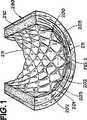
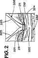
図1と2を参照すると、血管用ステント200が動脈壁210と係合して動脈290内に配置されて図解されている。図解の目的のみのため、図1−6で示す血管用ステントは当該技術で公知のパルマズ気球膨張型ステント(PalmazO balloon-expandable stent)であり、ステント200は内面201と外面202を有する。図1と2はステント200をそれが動脈290内に置かれた直後とステント200が、当該技術で公知の様に、動脈壁210内へ埋め込まれた後とで図解している。図1と2は血管用ステントを正しく置くことで一般的に特徴付けられることを図解している。ステント200はステンレス鋼又は当該技術で公知の他の金属材料製の、複数の金属部材、又はストラット、203を有するのが好ましい。図1と2に図解される様に、ステント200を正しく置くことが結果的に、ストラット203が該動脈壁210内に埋め込まれた後、該ストラット203の間に突出する組織のマウンド(mounds)211となる。又ストラット203は動脈壁210内にトラフ(troughs)又は線状の凹み(linear depressions)204を形成する。動脈290の阻止作用の度合(degree of blockage)及びステント200を置く前に使用された器具の種類と量により、該組織のマウンド211は内皮細胞(endothelial cells)を保持するかもしれない(図示せず)。
【0012】
図3と4を参照すると、時間の経過後、血栓215の薄い層が該凹み204を迅速に充たし、そしてステント200の内面201を覆う。図4で見られる様に、血栓215の縁216はは該ストラット203間に突出する組織のマウンド211に向かって羽状となる。組織マウンド211上に保持された該内皮細胞は動脈壁210の再内皮化(reendothelialization)を提供する。
【0013】
図5と6を参照すると、動脈壁210の内皮の再生は、矢印217に図解される様に、多数中心の仕方で(in a multicentric fashion )進み、内皮細胞は血栓215で覆われたステント200のストラット203へ、そしてその上へと移住する。該ステント200が、図1と2で図解される様に、適当に移植された、又は置かれたと仮定すると、満足すべき、迅速な内皮化は図7に示す様な薄い組織層218となる。当該技術で公知の様に、ステント200の適当な配置、又は埋め込みを達成するために、ステント200は僅かに過大に膨張されていなければならない。気球膨張型ステントのステント200の場合、ステント200の最終膨張用に選ばれた気球直径は、移植患部に近接した、動脈又は静脈のマッチした直径より10から15%大きくなければならない。図7に示す様に、動脈290の管腔219の直径Diは満足すべきものである。もし動脈壁210の再内皮化がステント配置前、又はその間に該ステントの不足膨張(underexpansion)又は該動脈壁の過剰な裸化(denudation)により害された場合、再内皮化はより遅くなる。これは増大した血栓堆積、筋細胞の増殖、そしてより厚いネオインチマル層の形成のために、管腔直径Diの減少となる。
【0014】
図8を参照すると、本発明の脈管内ステント300が図解されている。図解の目的のためのみにより、血管用のステント300の構造は、当該技術で公知の、パルマズ気球膨張型ステント(PalmazO balloon-expandable stent)で図解されており、その最初の、未膨張形状で図解されている。本発明の改良がこの後説明される如何なる構造を有する、如何なる材料製の如何なる血管内のステントでの使用にも好適であると信じられることは理解されるべきである。同様に、血管内のステントの製造方法に於ける本発明の改良も又この後説明される如何なる種類の血管内のステントの製造にも適用出来ると信じられる。
【0015】
図8に図解される様に、血管内のステント、又はステント、300は内面301、及び外面302を有しており、外面302は通常動脈壁210内に接触関係を有して埋め込まれる。本発明に依れば、ステント300の内面301は少なくとも1つの溝(groove)400を備え付けられている。望むならば、この後詳細に説明する様に、複数の溝400がステント300の内面301の上又は中に備え付けられることが可能である。この明細書を通してそして請求項内で用語”溝(groove)”の使用は、チャンネル(channel)又は凹み(depression)、ノッチ又はV字型又は丸いインデンテーション(indetation)、又は鋭い又はギザギザのある(jagged)何かで作られたスクラッチ(scratch)又はマーク(mark)として解釈されるよう意図されている。本発明の該少なくとも1つの溝400、又は複数の溝は、少なくとも1つの溝400を提供するためにステント300の内面301を研磨する(abrading)か、化学的又は機械的腐蝕(etching)工程、レーザ又はレーザ腐蝕(laser etching)工程の使用、ダイアモンドチップ付き工具(diamond-tipped tool)の使用、何等かの適当な研磨材料(abrasive material)の使用、又はこの後詳細に説明される様な、ステント300の内面301内、又はその上の望ましい溝、又は複数の溝、400を提供出来る、何等かの工具又は工程の使用の様な、何等かの好適な仕方でステント300の内面301の中、又はその上に、提供されてもよい。
【0016】
図8に示す様に、該少なくとも1つの溝、又は複数の溝、400は、ステント300の長手方向軸線305と実質的に平行に配置されたその長手方向軸線410を有して配置されている。代わって、溝400""により図解される様に、該少なくとも1つの溝400の長手方向軸線410はステント300の長手方向軸線305と実質的に直角に配置されてもよく、或いは溝400’により図解される様に、該溝の長手方向軸線410はステント300の長手方向軸線305に対して鈍角又は鋭角で配置されてもよい。溝400’が長手方向軸線305に対し作る角度は該角度がステント300の長手方向軸線305に対しどの方向から測定されるかに依って鋭角か鈍角か何れかになる。例えば、溝400’の長手方向軸線と長手方向軸線305の間の角度がもし矢印Aで示される様に測定されれば、該角度は鋭角である。もし該角度が、矢印Bの様に、測定されれば、該角度は鈍角である。
【0017】
なお図8を参照すると、複数の溝400がステント300の内面301上に提供されてもよく、2つの溝400は唯図解の目的のみのため示されている。溝400の様な、複数の個別溝の代わりに、ステント300の内面301を望むだけ多く覆うために、1つの溝400”がサーペンタイン式(in a serpentine fashion)に提供されてもよい。同様に、該溝は、溝400"’で示す様に、網目上の仕方、又はパターンで提供されることも可能である。対称又は非対称のパターンの溝を含め、望まれるどんなパターンの溝も提供するために、溝400,400’、400”400"’,そして400"”が望まれる様に、単独又は相互組み合わせで提供可能である。種々の溝400−400"”の角度的配置と位置は動脈201内でステント300が膨張時(図1)は変わり、変えられ、図8ではステント300はその未膨張形状で図解されていることは注意すべきである。同様に、もしステント300がワイヤ又は或る長さのワイヤで作られたステントである場合は、この様なワイヤ又はワイヤ部材上で形成された溝の配置と角度的配向はこの様なステントの膨張と移植時に同様に変えられる。該脈管内ステントの内面の上及びその全体での内皮細胞の移住レートを増加させるために、本発明の溝、又は複数の溝、が何等かの脈管内ステントの内面の中又は上に提供されることは、前に説明した様に、更に注意されるべきである。
【0018】
図9−16を参照して、溝400の種々の実施例を詳細に説明する。一般に、図9で見られる様に、溝400は幅W、深さD、及び長さLを有する(図8)。幅Wと深さDは、溝400の長さLに沿って同じで、変化しなくてもよい。代わって、該溝の幅Wは溝400の長さLに沿って変わってもよい。代わって、該溝の深さDは少なくとも1つの溝の長さLに沿って変わってもよい。代わって、該溝400の幅Wと深さDの双方共該少なくとも1つの溝の長さに沿って変わってもよい。同様に、図8に関連して説明した様に、溝又は複数の溝、400の位置と角度的配置に於ける様に、該溝、又は複数の溝、400の幅W、深さD、及び長さLは、望む様に変えることが出来て、溝400の種々の種類とパターンがステント300の内面301上に配置されることが可能である。
【0019】
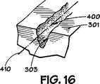
図9−16に示す様に、溝400は種々の異なる断面形状を有してもよい。望む様に、該溝又は複数の溝、400は該溝の長さLに沿って変化してもよく、或いは該溝の断面形状は該少なくとも1つの溝400の長さに沿っては変化しなくてもよい。同様に、該溝の断面形状の組み合わせを利用することも出来る。該溝又は複数の溝、400の断面形状は図8と9に図解する様に溝400の長手方向軸線401の周りに実質的に対称であってもよく、或いは該少なくとも1つの溝の断面形状は図14と16に図解する様に、該少なくとも1つの溝の長手方向軸線410の周りに実質的に対称であってもよい。該溝400の断面形状は種々の形を取ることが出来るが、その幾つかは図9−16に図解されており実質的に、正方形の形状であったり(図9)、U字型であったり(図10)、3角形、又はV型であったり(図11)、長方形であったり(図12)、そして3角形、又はキー溝型(図13)であったりする断面形状を含んでいる。各溝400の壁面303は図9−13に図解する様に実質的にスムーズでってもよく、或いは壁面303は図14−16に図解する様に、ギザギザであったり租であってもよい。図15に図解されている様に、壁面303は又もし望むならば少なくとも1つの突出部304と少なくとも1つのインデンテージョン(indentation)305を備え付けられることも出来て、そして望むならば追加の突出部とインデンテーション304,305を備え付けられることも可能である。
【0020】
溝、又は複数の溝、400の深さDは約2分の1から約10マイクロメートルの範囲内にあってもよい。溝、又は複数の溝、400の幅は約2から約40マイクロメートルの範囲内にあってもよい。ステント300上への内皮細胞の移住レートが害されないならば、勿論該幅Wと深さDは前記範囲から変わってもよい。溝400の長さLは図8の溝400の様に、ステント300の全長に延びてもよく、或いは溝の長さL’は図8の溝400"”の様に、ステント300の全長より短くてもよい。本発明の溝、又は複数の溝、はステント300の内面301に沿って連続していても、不連続であってもよい。
【0021】
本発明の溝、又は複数の溝、400を備え付けられなかったステント300の内面301の部分は、当該技術で公知の、電解研磨面の様な、どんな好適な、又は望ましい面仕上げを有してもよく、或いは望まれるどんな面仕上げ又はコーテイングを備え付けられてもよい。本発明の少なくとも1つの溝が血管内のステント300の内面301の上又は中に配置され、又は備え付けられた時は、ステント300の移植後、ステント300の内面301上への内皮細胞の移住レートは該内面301が本発明の少なくとも1つの溝を備え付けられなかった場合得られる移住レート以上に増加することが信じられる。
【0022】
明らかな変型や等価物が当業者には明らかななので、本発明が、示され図解された構造、動作、の精確な詳細又は精確な材料、実施例に限定されないことは理解されるべきである。従って、本発明はそれ故付属する請求項の範囲のみにより限定される。
【図面の簡単な説明】
【図1】 患者の動脈壁内に埋め込まれた脈管内ステントの部分の部分的断面斜視図である。
【図2】 2と呼称される図1の輪郭を描かれた部分の組立分解図である。
【図3】 時間経過後に於ける図1に対応する部分的断面斜視図である。
【図4】 4と呼称される図3の輪郭を描かれた部分の組立分解図である。
【図5】 時間の更に経過後の図1と3のステントと動脈の部分的断面図である。
【図6】 5と呼称される図5の輪郭を描かれた部分の組立分解図である。
【図7】 図5の7−7線に沿って取られた図5のステントと動脈の部分的断面図であり、該ステントを覆う薄いネオインチマルな(neointimal)層となる迅速な内皮形成(endothelialization)を図解している。
【図8】 本発明の未膨張の動脈内ステントの内部部分の平面図である。
【図9−16】 図8の9−9線に沿って取られた溝の組立分解図の種々の実施例であり、本発明の溝の種々の実施例の種々の断面形状と特性を図解している。[0001]
[Related Applications]
This application claims the benefit of US Provisional Application No. 60 / 064,916 filed Nov. 7, 1997.
[0002]
TECHNICAL FIELD OF THE INVENTION
The present invention relates to an intravascular stent and a method of manufacturing an intravascular stent, where the intravascular stent facilitates migration of endothelial cells onto the inner surface of the intravascular stent. Having its inner surface treated.
[0003]
[Description of related technology]
In recent years, various types of intravascular stents have been used. Intravascular stents generally refer to devices that include support for internal structures that are used to support living tissue during healing. When using a catheter device, intravascular stents, or stents placed within the lumen, have been shown to be very effective at initial recovery opening to sites of vascular occlusion. It was. Intravascular stents, or stents, are known as PalmazO and Palmaz-SchatzO balloon-expandable stents, Johnson & Johnson Inteventional Systems, Warren, NJ , of Warren, New Jersey), US Pat. Nos. 4,733,665 or 5,195,984, and other manufacturers' balloon inflation types as known in the art. It may be a balloon-expandable type, such as a stent. Other types of intravascular stents are self-expanding stents such as Nitinol coil stents or self-expanding stents made of stainless steel wire formed into a zigzag tubular shape. It is known as
[0004]
In general, intravascular stents are used as a mechanical means to solve the most common problems of percutaneous balloon angioplasty, such as elastic recoil and intimal dissection Is done. One problem in which endoluminal stent placement is involved with other revascularization procedures, including bypass surgery and balloon angioplasty, is restenosis of the artery. An important factor in promoting this possible reocclusion at the site of stent placement is the natural nonthrombogenic lining of the arterial lumen, the endothelium, Injury or disappearance. Along with the general thrombogenic nature of prosthic material, the matrix protein of the thrombogenic arterial wall is exposed. And activate the coagulation cascade. Depending on a number of factors, such as the activity of the fibrinolytic system, the use of anticoagulants, and the nature of the lesion substrate, the result of this process is a small mural To occlusive thrombus. Secondly, the disappearance of the endothelium at the interventional site is important for the development of the resulting eventual intimal hyperplasia and its progression. Previous studies have shown that the presence of an intact endothelial layer in the affected arterial lesion can significantly suppress the degree of smooth muscle cell-related intimal hyperplasia. It was. Not only the replacement surface of the stent, or the endothelialization of the prosthic surface, or the inner suface of the stent, but also the rapid re-endothelialization of the arterial wall is therefore to prevent slow flow thrombus and Important for continued patency. If endothelial cells from other sources are somehow introduced and not seeded into the affected area, covering the damaged area of the endothelium, at least initially, from the proximal arterial area of the intact endothelium This is mainly achieved through migration.
[0005]
An in vitro biological coating to a stent in the form of seeded endothelial cells on metal stents has been previously proposed, but has proven to be difficult to overcome There appears to be serious logistic problems with cell seeding. Thus, it is advantageous to increase the rate at which endothelial cells from the proximal arterial area of the intact endothelium migrate to the inner surface of the stent that is exposed to blood flow through the artery. Currently, most intravascular stents are made of stainless steel and such stents are implanted within the arterial wall several weeks to several months after tissue deployment. This favorable result is consistent with any stent design provided that it has a reasonably low metal surface and does not interfere with fluid flow through the artery, ie, blood flow. Furthermore, because of the fluid dynamics along the inner arterial wall caused by the pumping of blood through the artery along with the blood / endothelial interface itself, the endothelial cells on the stent surface It was desirable for the stent to have a very smooth surface to facilitate migration. In fact, the smoothness of the stent surface after expansion has been reported to be important for the biocompatibility of the stent, and thus any surface topography that differs from smoothness has been reported to be undesirable. "Christoph Helier, et al., Effects of surface tissue and charge on the biocompatibility of intravascular stents, coronary artery disease, vol. 6, 581-586, (1995) {Christoph Hehriein, et. Al., Influence of Surface Texture and Charge On the Biocompatibility of Endovascular Stents, Coronary Artery Disease, Vol. 6, pages 581-586 (1995)} ”. After the stent is coated with serum protein, the endothelium is covered with a fibrin-coated metal surface on the inner surface of the stent until a continuous layer of endothelium covers the stent surface within days to weeks. metal surface). The endothelium allows the thrombogenic metal surface to be protected from thrombus deposition that is likely to form with slow or turbulent flow. Currently, all intravascular stents made of stainless steel or other alloys or metals are equipped with an extremely smooth surface finish, usually obtained by electropolishing the surface of the metal stent. ing. Although currently known intravascular stents have been shown to be successful in treating coronary artery disease, particularly including PalmazO and Palmaz-SchatzO balloon-expandable stents, If the rate and / or rate of endothelial cell migration on the inner surface can be increased, the intravascular stent may be even more successful as an adjunct to balloon angioplasty. Accordingly, the art has sought an intravascular stent and a method of manufacturing an intravascular stent that increases the rate of migration of endothelial cells onto the inner surface of the stent after it has been implanted.
[0006]
SUMMARY OF THE INVENTION
In accordance with the present invention, the above advantages have been achieved through an intravascular stent of the present invention having an outer surface and an inner surface. The present invention includes improvements in such intravascular stents and improvements in the method of manufacturing such intravascular stents by providing at least one groove disposed on the inner surface of the stent. . A further feature of the invention is that the at least one groove has a width, a length, and a depth, and the width and depth do not vary along the length of the at least one groove. It is. A further feature of the invention is that the width of the groove may vary along the length of the at least one groove, and the depth of the groove varies along the length of the at least one groove. And both the width and the depth may vary along the length of the at least one groove.
[0007]
Another feature of the invention is that the at least one groove has a length, a longitudinal axis, and a cross-sectional shape, the cross-sectional shape of the at least one groove being the length of the at least one groove. It may vary along. An additional feature of the present invention is that the cross-sectional shape of the at least one groove does not change along the length of the at least one groove. A further feature of the present invention is that the cross-sectional shape of the at least one groove is substantially symmetric about the longitudinal axis of the at least one groove, or about the longitudinal axis of the at least one groove. Substantially asymmetric, substantially triangular, substantially rectangular, substantially square, substantially U-shaped, or It may be substantially V-shaped.
[0008]
A further feature of the present invention is that the longitudinal axis of the at least one groove is substantially parallel to the longitudinal axis of the stent or substantially perpendicular to the longitudinal axis of the stent. It may be arranged at an obtuse angle with respect to the longitudinal axis or at an acute angle with respect to the longitudinal axis of the stent. An additional feature of the present invention is that the groove has a depth in the range of about one-half to about 10 micrometers, and the at least one groove has a width in the range of about 2 to about 40 micrometers. Is to have.
[0009]
The improvement of the intravascular stent and the method of manufacturing the intravascular stent of the present invention is that the migration of endothelial cells onto the inner surface of the intravascular stent as compared to the currently known intravascular stent and the method of manufacturing such a stent. Has the advantage of improving the rate.
[0010]
While the invention will be described in conjunction with the preferred embodiment, it will be understood that it is not intended to limit the invention to that embodiment. On the contrary, all alternatives, modifications, and equivalents are intended to be covered as included within the spirit and scope of the invention as defined by the appended claims.
[0011]
[Detailed Description of the Invention]
With reference to FIGS. 1 and 2, a
[0012]
Referring to FIGS. 3 and 4, after time, a thin layer of
[0013]
With reference to FIGS. 5 and 6, the regeneration of the endothelium of the
[0014]
Referring to FIG. 8, an
[0015]
As illustrated in FIG. 8, an intravascular stent, or stent, 300 has an
[0016]
As shown in FIG. 8, the at least one groove or plurality of grooves, 400, is disposed with its
[0017]
Still referring to FIG. 8, a plurality of
[0018]
Various embodiments of the
[0019]
As shown in FIGS. 9-16, the
[0020]
The depth D of the groove or
[0021]
The portion of the
[0022]
Since obvious variations and equivalents will be apparent to those skilled in the art, it is to be understood that the invention is not limited to the precise details or precise materials, examples of construction and operation shown and illustrated. . Accordingly, the invention is therefore limited only by the scope of the appended claims.
[Brief description of the drawings]
FIG. 1 is a partial cross-sectional perspective view of a portion of an intravascular stent implanted within a patient's arterial wall.
FIG. 2 is an exploded view of the outlined portion of FIG.
FIG. 3 is a partial cross-sectional perspective view corresponding to FIG. 1 after a lapse of time.
4 is an exploded view of the outlined portion of FIG.
FIG. 5 is a partial cross-sectional view of the stent and artery of FIGS. 1 and 3 after a further passage of time.
6 is an exploded view of the outlined portion of FIG. 5 designated 5;
7 is a partial cross-sectional view of the stent and artery of FIG. 5 taken along line 7-7 of FIG. 5, with rapid endothelium formation resulting in a thin neointimal layer covering the stent. (Endothelialization) is illustrated.
FIG. 8 is a plan view of the internal portion of the unexpanded intra-arterial stent of the present invention.
9-16 are various embodiments of an exploded view of the groove taken along line 9-9 of FIG. 8, illustrating various cross-sectional shapes and characteristics of various embodiments of the groove of the present invention. is doing.
Claims (44)
Translated fromJapanese該ステントの該内面内に配置された少なくとも1つの溝、該少なくとも1つの溝は、該ステントが埋め込まれた後、該ステントの該内面上への内皮細胞の移住レートを増加させるのに適した形状を有するように形成され、ここで該少なくとも1つの溝は巾と該巾より大きい寸法を有する長さと深さを有し、該深さは該ステントの該内面と該外面の間の距離より小さいものである、を具備することを特徴とする改良された金属製の脈管内ステント。In a metal intravascular stent having an outer surface and an inner surface,
At least one groove disposed within the inner surface of the stent, wherein the at least onegroove is suitable for increasing the rate of migration of endothelial cells onto the inner surface of the stent after the stent is implanted. The at least one groove has a width and a length and depth having dimensions greater than the width, the depth being greater than the distance between the inner surface and the outer surface of the stent. An improved intravascular stent made of metal, characterized inthat it is small .
該ステントの該内面内に少なくとも1つの溝、該少なくとも1つの溝は、該ステントが埋め込まれた後、該ステントの該内面上への内皮細胞の移住レートを増加させるのに適した形状を有するように形成され、ここで該少なくとも1つの溝は巾と該巾より大きい寸法を有する長さと深さを有し、該深さは該ステントの該内面と該外面の間の距離より小さいものである、を提供する過程を具備することを特徴とする金属製の脈管内ステントの製造方法。In a method for manufacturing a metal intravascular stent, the stent has an outer surface and an inner surface;
At least one groove within the inner surface of the stent, the at least one groovehaving a shape suitable for increasing the rate of migration of endothelial cells onto the inner surface of the stent after the stent is implanted Wherein the at least one groove has a width and a length and depth having dimensions greater than the width, the depth being less than the distance between the inner surface and the outer surface of the stent. A method for producing a metallic intravascular stent, comprisingthe step of providing acertain .
Applications Claiming Priority (3)
| Application Number | Priority Date | Filing Date | Title |
|---|---|---|---|
| US6491697P | 1997-11-07 | 1997-11-07 | |
| US60/064,916 | 1997-11-07 | ||
| PCT/US1998/023609WO1999023977A1 (en) | 1997-11-07 | 1998-11-05 | Intravascular stent and method for manufacturing an intravascular stent |
Publications (2)
| Publication Number | Publication Date |
|---|---|
| JP2001522640A JP2001522640A (en) | 2001-11-20 |
| JP4172912B2true JP4172912B2 (en) | 2008-10-29 |
Family
ID=22059114
Family Applications (1)
| Application Number | Title | Priority Date | Filing Date |
|---|---|---|---|
| JP2000520076AExpired - Fee RelatedJP4172912B2 (en) | 1997-11-07 | 1998-11-05 | Intravascular stent and method for manufacturing the intravascular stent |
Country Status (7)
| Country | Link |
|---|---|
| US (1) | US6190404B1 (en) |
| EP (1) | EP1028672B2 (en) |
| JP (1) | JP4172912B2 (en) |
| AU (1) | AU749980B2 (en) |
| CA (1) | CA2308177C (en) |
| DE (1) | DE69830605T3 (en) |
| WO (1) | WO1999023977A1 (en) |
Families Citing this family (164)
| Publication number | Priority date | Publication date | Assignee | Title |
|---|---|---|---|---|
| AU713514B2 (en)* | 1994-10-19 | 1999-12-02 | Arterial Vascular Engineering, Inc | Stent surface anchor |
| US20040106985A1 (en) | 1996-04-26 | 2004-06-03 | Jang G. David | Intravascular stent |
| JP4636634B2 (en)* | 1996-04-26 | 2011-02-23 | ボストン サイエンティフィック サイムド,インコーポレイテッド | Intravascular stent |
| US20040225347A1 (en)* | 2000-06-05 | 2004-11-11 | Lang G. David | Intravascular stent with increasing coating retaining capacity |
| US6783543B2 (en) | 2000-06-05 | 2004-08-31 | Scimed Life Systems, Inc. | Intravascular stent with increasing coating retaining capacity |
| US6235053B1 (en) | 1998-02-02 | 2001-05-22 | G. David Jang | Tubular stent consists of chevron-shape expansion struts and contralaterally attached diagonal connectors |
| US5954743A (en)* | 1996-04-26 | 1999-09-21 | Jang; G. David | Intravascular stent |
| US6241760B1 (en)* | 1996-04-26 | 2001-06-05 | G. David Jang | Intravascular stent |
| US7341598B2 (en) | 1999-01-13 | 2008-03-11 | Boston Scientific Scimed, Inc. | Stent with protruding branch portion for bifurcated vessels |
| US6102942A (en)* | 1998-03-30 | 2000-08-15 | Endovascular Technologies, Inc. | Stent/graft deployment catheter with a stent/graft attachment mechanism |
| US7179289B2 (en) | 1998-03-30 | 2007-02-20 | Conor Medsystems, Inc. | Expandable medical device for delivery of beneficial agent |
| US7713297B2 (en) | 1998-04-11 | 2010-05-11 | Boston Scientific Scimed, Inc. | Drug-releasing stent with ceramic-containing layer |
| WO2000010623A1 (en)* | 1998-08-25 | 2000-03-02 | Tricardia, L.L.C. | An implantable device for promoting repair of a body lumen |
| US20060216313A1 (en)* | 1999-08-10 | 2006-09-28 | Allergan, Inc. | Methods for treating a stricture with a botulinum toxin |
| US6767544B2 (en)* | 2002-04-01 | 2004-07-27 | Allergan, Inc. | Methods for treating cardiovascular diseases with botulinum toxin |
| US6254631B1 (en)* | 1999-09-23 | 2001-07-03 | Intratherapeutics, Inc. | Stent with enhanced friction |
| US6733513B2 (en) | 1999-11-04 | 2004-05-11 | Advanced Bioprosthetic Surfaces, Ltd. | Balloon catheter having metal balloon and method of making same |
| US6379383B1 (en)* | 1999-11-19 | 2002-04-30 | Advanced Bio Prosthetic Surfaces, Ltd. | Endoluminal device exhibiting improved endothelialization and method of manufacture thereof |
| US7300457B2 (en) | 1999-11-19 | 2007-11-27 | Advanced Bio Prosthetic Surfaces, Ltd. | Self-supporting metallic implantable grafts, compliant implantable medical devices and methods of making same |
| US8458879B2 (en) | 2001-07-03 | 2013-06-11 | Advanced Bio Prosthetic Surfaces, Ltd., A Wholly Owned Subsidiary Of Palmaz Scientific, Inc. | Method of fabricating an implantable medical device |
| US6849085B2 (en) | 1999-11-19 | 2005-02-01 | Advanced Bio Prosthetic Surfaces, Ltd. | Self-supporting laminated films, structural materials and medical devices manufactured therefrom and method of making same |
| US7235092B2 (en) | 1999-11-19 | 2007-06-26 | Advanced Bio Prosthetic Surfaces, Ltd. | Guidewires and thin film catheter-sheaths and method of making same |
| US7195641B2 (en) | 1999-11-19 | 2007-03-27 | Advanced Bio Prosthetic Surfaces, Ltd. | Valvular prostheses having metal or pseudometallic construction and methods of manufacture |
| US10172730B2 (en) | 1999-11-19 | 2019-01-08 | Vactronix Scientific, Llc | Stents with metallic covers and methods of making same |
| US7736687B2 (en)* | 2006-01-31 | 2010-06-15 | Advance Bio Prosthetic Surfaces, Ltd. | Methods of making medical devices |
| US6537310B1 (en) | 1999-11-19 | 2003-03-25 | Advanced Bio Prosthetic Surfaces, Ltd. | Endoluminal implantable devices and method of making same |
| US6936066B2 (en)* | 1999-11-19 | 2005-08-30 | Advanced Bio Prosthetic Surfaces, Ltd. | Complaint implantable medical devices and methods of making same |
| US9566148B2 (en) | 2000-05-12 | 2017-02-14 | Vactronix Scientific, Inc. | Self-supporting laminated films, structural materials and medical devices manufactured therefrom and methods of making same |
| US8632583B2 (en) | 2011-05-09 | 2014-01-21 | Palmaz Scientific, Inc. | Implantable medical device having enhanced endothelial migration features and methods of making the same |
| US20120185037A1 (en)* | 2000-05-19 | 2012-07-19 | Palmaz Scientific, Inc. | Grooved drug-eluting medical devices and method of making same |
| AU2001264750B2 (en)* | 2000-05-19 | 2006-08-31 | Vactronix Scientific, Llc | Methods and apparatus for manufacturing an intravascular stent |
| US8252044B1 (en) | 2000-11-17 | 2012-08-28 | Advanced Bio Prosthestic Surfaces, Ltd. | Device for in vivo delivery of bioactive agents and method of manufacture thereof |
| JP4754714B2 (en) | 2000-06-01 | 2011-08-24 | テルモ株式会社 | Intraluminal indwelling |
| US6709451B1 (en)* | 2000-07-14 | 2004-03-23 | Norman Noble, Inc. | Channeled vascular stent apparatus and method |
| US7766956B2 (en) | 2000-09-22 | 2010-08-03 | Boston Scientific Scimed, Inc. | Intravascular stent and assembly |
| US6254632B1 (en)* | 2000-09-28 | 2001-07-03 | Advanced Cardiovascular Systems, Inc. | Implantable medical device having protruding surface structures for drug delivery and cover attachment |
| EP1498084B1 (en)* | 2000-10-16 | 2014-06-18 | Innovational Holdings, LLC | Expandable medical device for delivery of beneficial agent |
| WO2002038080A2 (en)* | 2000-11-07 | 2002-05-16 | Advanced Bio Prosthetic Surfaces, Ltd. | Endoluminal stent, self-fupporting endoluminal graft and methods of making same |
| US8372139B2 (en) | 2001-02-14 | 2013-02-12 | Advanced Bio Prosthetic Surfaces, Ltd. | In vivo sensor and method of making same |
| US6752829B2 (en)* | 2001-01-30 | 2004-06-22 | Scimed Life Systems, Inc. | Stent with channel(s) for containing and delivering a biologically active material and method for manufacturing the same |
| US20040073294A1 (en) | 2002-09-20 | 2004-04-15 | Conor Medsystems, Inc. | Method and apparatus for loading a beneficial agent into an expandable medical device |
| WO2003002243A2 (en) | 2001-06-27 | 2003-01-09 | Remon Medical Technologies Ltd. | Method and device for electrochemical formation of therapeutic species in vivo |
| US6979346B1 (en)* | 2001-08-08 | 2005-12-27 | Advanced Cardiovascular Systems, Inc. | System and method for improved stent retention |
| US7056338B2 (en) | 2003-03-28 | 2006-06-06 | Conor Medsystems, Inc. | Therapeutic agent delivery device with controlled therapeutic agent release rates |
| US7014654B2 (en)* | 2001-11-30 | 2006-03-21 | Scimed Life Systems, Inc. | Stent designed for the delivery of therapeutic substance or other agents |
| US6850804B2 (en)* | 2002-01-18 | 2005-02-01 | Calfacior Corporation | System method and apparatus for localized heating of tissue |
| US6993394B2 (en) | 2002-01-18 | 2006-01-31 | Calfacion Corporation | System method and apparatus for localized heating of tissue |
| US7048756B2 (en)* | 2002-01-18 | 2006-05-23 | Apasara Medical Corporation | System, method and apparatus for evaluating tissue temperature |
| US7162302B2 (en)* | 2002-03-04 | 2007-01-09 | Nanoset Llc | Magnetically shielded assembly |
| US20050260331A1 (en)* | 2002-01-22 | 2005-11-24 | Xingwu Wang | Process for coating a substrate |
| US6846985B2 (en) | 2002-01-22 | 2005-01-25 | Nanoset, Llc | Magnetically shielded assembly |
| US20040225213A1 (en)* | 2002-01-22 | 2004-11-11 | Xingwu Wang | Magnetic resonance imaging coated assembly |
| US7091412B2 (en)* | 2002-03-04 | 2006-08-15 | Nanoset, Llc | Magnetically shielded assembly |
| DE10235689A1 (en)* | 2002-07-31 | 2004-02-19 | Biotronik Meß- und Therapiegeräte GmbH & Co. Ingenieurbüro Berlin | Implant to administer small doses of an active agent directly into the bloodstream at a blood vessel, comprising a base body against the blood vessel wall with micro-injectors through the artery wall |
| AU2003270817B2 (en)* | 2002-09-26 | 2009-09-17 | Vactronix Scientific, Llc | High strength vacuum deposited nitionol alloy films, medical thin film graft materials and method of making same |
| AU2003272710B2 (en) | 2002-09-26 | 2008-05-15 | Vactronix Scientific, Llc | Implantable materials having engineered surfaces and method of making same |
| US8268340B2 (en) | 2002-09-26 | 2012-09-18 | Advanced Bio Prosthetic Surfaces, Ltd. | Implantable materials having engineered surfaces and method of making same |
| US8679517B2 (en)* | 2002-09-26 | 2014-03-25 | Palmaz Scientific, Inc. | Implantable materials having engineered surfaces made by vacuum deposition and method of making same |
| US6923829B2 (en) | 2002-11-25 | 2005-08-02 | Advanced Bio Prosthetic Surfaces, Ltd. | Implantable expandable medical devices having regions of differential mechanical properties and methods of making same |
| US7044965B1 (en)* | 2002-12-13 | 2006-05-16 | Spielberg Theodore E | Therapeutic cellular stent |
| AU2004226327A1 (en) | 2003-03-28 | 2004-10-14 | Innovational Holdings, Llc | Implantable medical device with beneficial agent concentration gradient |
| EP1620047B1 (en) | 2003-05-07 | 2009-11-11 | Advanced Bio Prosthetic Surfaces, Ltd. | Metallic implantable grafts and method of making same |
| US20040243221A1 (en)* | 2003-05-27 | 2004-12-02 | Fawzi Natalie V. | Endovascular graft including substructure for positioning and sealing within vasculature |
| GB0315714D0 (en)* | 2003-07-04 | 2003-08-13 | Tayside Flow Technologies Ltd | An internal formation for a conduit |
| US20050027350A1 (en)* | 2003-07-30 | 2005-02-03 | Biotronik Mess-Und Therapiegeraete Gmbh & Co Ingenieurbuero Berlin | Endovascular implant for the injection of an active substance into the media of a blood vessel |
| JP2005128771A (en)* | 2003-10-23 | 2005-05-19 | Fujitsu Ltd | Data file system, data access server, and data access program |
| US8435285B2 (en) | 2003-11-25 | 2013-05-07 | Boston Scientific Scimed, Inc. | Composite stent with inner and outer stent elements and method of using the same |
| US7901447B2 (en)* | 2004-12-29 | 2011-03-08 | Boston Scientific Scimed, Inc. | Medical devices including a metallic film and at least one filament |
| US20050197687A1 (en)* | 2004-03-02 | 2005-09-08 | Masoud Molaei | Medical devices including metallic films and methods for making same |
| US20060142838A1 (en)* | 2004-12-29 | 2006-06-29 | Masoud Molaei | Medical devices including metallic films and methods for loading and deploying same |
| US8998973B2 (en)* | 2004-03-02 | 2015-04-07 | Boston Scientific Scimed, Inc. | Medical devices including metallic films |
| US8632580B2 (en)* | 2004-12-29 | 2014-01-21 | Boston Scientific Scimed, Inc. | Flexible medical devices including metallic films |
| US8992592B2 (en)* | 2004-12-29 | 2015-03-31 | Boston Scientific Scimed, Inc. | Medical devices including metallic films |
| US8591568B2 (en)* | 2004-03-02 | 2013-11-26 | Boston Scientific Scimed, Inc. | Medical devices including metallic films and methods for making same |
| CN101193606A (en)* | 2004-03-04 | 2008-06-04 | 拜罗克国际公司 | Surgical stent with micro-geometrically patterned surface |
| JP5054524B2 (en) | 2004-06-08 | 2012-10-24 | アドバンスド ステント テクノロジーズ, インコーポレイテッド | Stent with protruding branch for branch pipe |
| US7585318B2 (en)* | 2004-06-18 | 2009-09-08 | Boston Scientific Scimed, Inc. | Medical devices and methods of making the same |
| US20060054604A1 (en)* | 2004-09-10 | 2006-03-16 | Saunders Richard J | Laser process to produce drug delivery channel in metal stents |
| CN1605366A (en)* | 2004-12-03 | 2005-04-13 | 北京美中双和医疗器械有限公司 | Vascular stent mounted with non penetrable slot or blind hole and its preparing method |
| US20060127443A1 (en)* | 2004-12-09 | 2006-06-15 | Helmus Michael N | Medical devices having vapor deposited nanoporous coatings for controlled therapeutic agent delivery |
| US8221824B2 (en)* | 2005-02-03 | 2012-07-17 | Boston Scientific Scimed, Inc. | Deforming surface of drug eluting coating to alter drug release profile of a medical device |
| US7854760B2 (en)* | 2005-05-16 | 2010-12-21 | Boston Scientific Scimed, Inc. | Medical devices including metallic films |
| US8187327B2 (en)* | 2005-05-18 | 2012-05-29 | Kyphon Sarl | Selectively-expandable bone scaffold |
| US20070038176A1 (en)* | 2005-07-05 | 2007-02-15 | Jan Weber | Medical devices with machined layers for controlled communications with underlying regions |
| US7935379B2 (en)* | 2005-11-14 | 2011-05-03 | Boston Scientific Scimed, Inc. | Coated and imprinted medical devices and methods of making the same |
| US20070112421A1 (en)* | 2005-11-14 | 2007-05-17 | O'brien Barry | Medical device with a grooved surface |
| US7540881B2 (en) | 2005-12-22 | 2009-06-02 | Boston Scientific Scimed, Inc. | Bifurcation stent pattern |
| US8840660B2 (en) | 2006-01-05 | 2014-09-23 | Boston Scientific Scimed, Inc. | Bioerodible endoprostheses and methods of making the same |
| US8089029B2 (en)* | 2006-02-01 | 2012-01-03 | Boston Scientific Scimed, Inc. | Bioabsorbable metal medical device and method of manufacture |
| US20070224235A1 (en) | 2006-03-24 | 2007-09-27 | Barron Tenney | Medical devices having nanoporous coatings for controlled therapeutic agent delivery |
| US8187620B2 (en) | 2006-03-27 | 2012-05-29 | Boston Scientific Scimed, Inc. | Medical devices comprising a porous metal oxide or metal material and a polymer coating for delivering therapeutic agents |
| US8048150B2 (en) | 2006-04-12 | 2011-11-01 | Boston Scientific Scimed, Inc. | Endoprosthesis having a fiber meshwork disposed thereon |
| US20070264303A1 (en)* | 2006-05-12 | 2007-11-15 | Liliana Atanasoska | Coating for medical devices comprising an inorganic or ceramic oxide and a therapeutic agent |
| US8815275B2 (en) | 2006-06-28 | 2014-08-26 | Boston Scientific Scimed, Inc. | Coatings for medical devices comprising a therapeutic agent and a metallic material |
| WO2008002778A2 (en) | 2006-06-29 | 2008-01-03 | Boston Scientific Limited | Medical devices with selective coating |
| EP2054537A2 (en) | 2006-08-02 | 2009-05-06 | Boston Scientific Scimed, Inc. | Endoprosthesis with three-dimensional disintegration control |
| EP2068757B1 (en) | 2006-09-14 | 2011-05-11 | Boston Scientific Limited | Medical devices with drug-eluting coating |
| EP2959925B1 (en) | 2006-09-15 | 2018-08-29 | Boston Scientific Limited | Medical devices and methods of making the same |
| ES2357661T3 (en) | 2006-09-15 | 2011-04-28 | Boston Scientific Scimed, Inc. | BIOEROSIONABLE ENDOPROOTHESIS WITH BIOESTABLE INORGANIC LAYERS. |
| WO2008034066A1 (en)* | 2006-09-15 | 2008-03-20 | Boston Scientific Limited | Bioerodible endoprostheses and methods of making the same |
| JP2010503489A (en) | 2006-09-15 | 2010-02-04 | ボストン サイエンティフィック リミテッド | Biodegradable endoprosthesis and method for producing the same |
| WO2008036548A2 (en) | 2006-09-18 | 2008-03-27 | Boston Scientific Limited | Endoprostheses |
| US7875069B2 (en)* | 2006-09-21 | 2011-01-25 | Boston Scientific Scimed, Inc. | Stent with support element |
| WO2008045184A1 (en)* | 2006-10-05 | 2008-04-17 | Boston Scientific Limited | Polymer-free coatings for medical devices formed by plasma electrolytic deposition |
| US7951191B2 (en) | 2006-10-10 | 2011-05-31 | Boston Scientific Scimed, Inc. | Bifurcated stent with entire circumferential petal |
| US7981150B2 (en) | 2006-11-09 | 2011-07-19 | Boston Scientific Scimed, Inc. | Endoprosthesis with coatings |
| US7832251B2 (en)* | 2006-11-15 | 2010-11-16 | Abbott Laboratories | Patterned mold for medical device |
| US7842082B2 (en) | 2006-11-16 | 2010-11-30 | Boston Scientific Scimed, Inc. | Bifurcated stent |
| US20080140179A1 (en)* | 2006-12-12 | 2008-06-12 | Ladisa John F | Apparatus and method for minimizing flow disturbances in a stented region of a lumen |
| ES2506144T3 (en) | 2006-12-28 | 2014-10-13 | Boston Scientific Limited | Bioerodible endoprosthesis and their manufacturing procedure |
| US8114466B2 (en)* | 2007-01-03 | 2012-02-14 | Boston Scientific Scimed, Inc. | Methods of applying coating to the inside surface of a stent |
| US7682388B2 (en) | 2007-01-30 | 2010-03-23 | Medtronic Vascular, Inc. | Stent with longitudinal groove |
| US8431149B2 (en) | 2007-03-01 | 2013-04-30 | Boston Scientific Scimed, Inc. | Coated medical devices for abluminal drug delivery |
| US8070797B2 (en) | 2007-03-01 | 2011-12-06 | Boston Scientific Scimed, Inc. | Medical device with a porous surface for delivery of a therapeutic agent |
| US8067054B2 (en) | 2007-04-05 | 2011-11-29 | Boston Scientific Scimed, Inc. | Stents with ceramic drug reservoir layer and methods of making and using the same |
| US20080275543A1 (en)* | 2007-05-02 | 2008-11-06 | Boston Scientific Scimed, Inc. | Stent |
| US7976915B2 (en)* | 2007-05-23 | 2011-07-12 | Boston Scientific Scimed, Inc. | Endoprosthesis with select ceramic morphology |
| DE102007029672A1 (en) | 2007-06-27 | 2009-01-02 | Lzh Laserzentrum Hannover E.V. | Implant and method for its production |
| US20090011117A1 (en)* | 2007-07-03 | 2009-01-08 | Endotronix, Inc. | Methods for texturing a surface of an endovascular implant |
| US8002823B2 (en) | 2007-07-11 | 2011-08-23 | Boston Scientific Scimed, Inc. | Endoprosthesis coating |
| US7942926B2 (en) | 2007-07-11 | 2011-05-17 | Boston Scientific Scimed, Inc. | Endoprosthesis coating |
| EP2187988B1 (en) | 2007-07-19 | 2013-08-21 | Boston Scientific Limited | Endoprosthesis having a non-fouling surface |
| US8815273B2 (en) | 2007-07-27 | 2014-08-26 | Boston Scientific Scimed, Inc. | Drug eluting medical devices having porous layers |
| US7931683B2 (en) | 2007-07-27 | 2011-04-26 | Boston Scientific Scimed, Inc. | Articles having ceramic coated surfaces |
| WO2009018340A2 (en) | 2007-07-31 | 2009-02-05 | Boston Scientific Scimed, Inc. | Medical device coating by laser cladding |
| JP2010535541A (en) | 2007-08-03 | 2010-11-25 | ボストン サイエンティフィック リミテッド | Coating for medical devices with large surface area |
| US7959669B2 (en) | 2007-09-12 | 2011-06-14 | Boston Scientific Scimed, Inc. | Bifurcated stent with open ended side branch support |
| US8052745B2 (en) | 2007-09-13 | 2011-11-08 | Boston Scientific Scimed, Inc. | Endoprosthesis |
| US20090076591A1 (en)* | 2007-09-19 | 2009-03-19 | Boston Scientific Scimed, Inc. | Stent Design Allowing Extended Release of Drug and/or Enhanced Adhesion of Polymer to OD Surface |
| US8216632B2 (en) | 2007-11-02 | 2012-07-10 | Boston Scientific Scimed, Inc. | Endoprosthesis coating |
| US7938855B2 (en) | 2007-11-02 | 2011-05-10 | Boston Scientific Scimed, Inc. | Deformable underlayer for stent |
| US8029554B2 (en) | 2007-11-02 | 2011-10-04 | Boston Scientific Scimed, Inc. | Stent with embedded material |
| US20090118813A1 (en)* | 2007-11-02 | 2009-05-07 | Torsten Scheuermann | Nano-patterned implant surfaces |
| US7833266B2 (en)* | 2007-11-28 | 2010-11-16 | Boston Scientific Scimed, Inc. | Bifurcated stent with drug wells for specific ostial, carina, and side branch treatment |
| US8277501B2 (en) | 2007-12-21 | 2012-10-02 | Boston Scientific Scimed, Inc. | Bi-stable bifurcated stent petal geometry |
| JP2011510751A (en)* | 2008-02-01 | 2011-04-07 | ボストン サイエンティフィック サイムド,インコーポレイテッド | Medical device coated with a drug that separates and releases the drug |
| US8920491B2 (en) | 2008-04-22 | 2014-12-30 | Boston Scientific Scimed, Inc. | Medical devices having a coating of inorganic material |
| US8932346B2 (en) | 2008-04-24 | 2015-01-13 | Boston Scientific Scimed, Inc. | Medical devices having inorganic particle layers |
| US7998192B2 (en) | 2008-05-09 | 2011-08-16 | Boston Scientific Scimed, Inc. | Endoprostheses |
| US8932340B2 (en) | 2008-05-29 | 2015-01-13 | Boston Scientific Scimed, Inc. | Bifurcated stent and delivery system |
| US8236046B2 (en) | 2008-06-10 | 2012-08-07 | Boston Scientific Scimed, Inc. | Bioerodible endoprosthesis |
| EP2303350A2 (en) | 2008-06-18 | 2011-04-06 | Boston Scientific Scimed, Inc. | Endoprosthesis coating |
| US20100004733A1 (en)* | 2008-07-02 | 2010-01-07 | Boston Scientific Scimed, Inc. | Implants Including Fractal Structures |
| US7951193B2 (en)* | 2008-07-23 | 2011-05-31 | Boston Scientific Scimed, Inc. | Drug-eluting stent |
| US7985252B2 (en) | 2008-07-30 | 2011-07-26 | Boston Scientific Scimed, Inc. | Bioerodible endoprosthesis |
| US8382824B2 (en) | 2008-10-03 | 2013-02-26 | Boston Scientific Scimed, Inc. | Medical implant having NANO-crystal grains with barrier layers of metal nitrides or fluorides |
| US8231980B2 (en) | 2008-12-03 | 2012-07-31 | Boston Scientific Scimed, Inc. | Medical implants including iridium oxide |
| EP2403546A2 (en) | 2009-03-02 | 2012-01-11 | Boston Scientific Scimed, Inc. | Self-buffering medical implants |
| US8071156B2 (en)* | 2009-03-04 | 2011-12-06 | Boston Scientific Scimed, Inc. | Endoprostheses |
| US8287937B2 (en) | 2009-04-24 | 2012-10-16 | Boston Scientific Scimed, Inc. | Endoprosthese |
| US8668732B2 (en) | 2010-03-23 | 2014-03-11 | Boston Scientific Scimed, Inc. | Surface treated bioerodible metal endoprostheses |
| WO2011122344A1 (en)* | 2010-03-30 | 2011-10-06 | テルモ株式会社 | Stent |
| EP2422827B1 (en) | 2010-08-27 | 2019-01-30 | Biotronik AG | Stent with a surface layer having a topographic modification |
| US8329021B2 (en)* | 2010-10-28 | 2012-12-11 | Palmaz Scientific, Inc. | Method for mass transfer of micro-patterns onto medical devices |
| US8728563B2 (en)* | 2011-05-03 | 2014-05-20 | Palmaz Scientific, Inc. | Endoluminal implantable surfaces, stents, and grafts and method of making same |
| US11045297B2 (en) | 2012-10-18 | 2021-06-29 | Vactronix Scientific Llc | Topographical features and patterns on a surface of a medical device and methods of making the same |
| US9050394B2 (en) | 2011-05-09 | 2015-06-09 | Palmaz Scientific, Inc. | Method for making topographical features on a surface of a medical device |
| US12226301B2 (en) | 2011-05-09 | 2025-02-18 | Vactronix Scientific, Llc | Method of making topographical features and patterns on a surface of a medical device |
| CA2845808A1 (en)* | 2011-08-19 | 2013-03-28 | Advanced Bio Prosthetic Surfaces, Ltd. | Grooved drug-eluting medical devices and method of making same |
| US9566633B2 (en) | 2012-11-15 | 2017-02-14 | Vactronix Scientific, Inc. | Stents having a hybrid pattern and methods of manufacture |
| US10271975B2 (en) | 2013-03-15 | 2019-04-30 | Atrium Medical Corporation | Stent device having reduced foreshortening and recoil and method of making same |
| CN106510818B (en)* | 2016-11-22 | 2019-08-23 | 中国人民解放军第四军医大学 | A kind of modular construction improving external fixator for orthopedics dep percutaneously sealing effect |
| CN106618816A (en)* | 2016-11-22 | 2017-05-10 | 中国人民解放军第四军医大学 | Novel prosthetic limb connecting device |
| CN109223253A (en)* | 2018-08-16 | 2019-01-18 | 河南科技大学第附属医院 | A kind of breast prosthesis |
Family Cites Families (15)
| Publication number | Priority date | Publication date | Assignee | Title |
|---|---|---|---|---|
| US3276448A (en)† | 1962-12-14 | 1966-10-04 | Ethicon Inc | Collagen coated fabric prosthesis |
| AR229309A1 (en)* | 1983-04-20 | 1983-07-15 | Barone Hector Daniel | MOUNT FOR CARDIAC VALVES |
| US4733665C2 (en) | 1985-11-07 | 2002-01-29 | Expandable Grafts Partnership | Expandable intraluminal graft and method and apparatus for implanting an expandable intraluminal graft |
| US5102417A (en) | 1985-11-07 | 1992-04-07 | Expandable Grafts Partnership | Expandable intraluminal graft, and method and apparatus for implanting an expandable intraluminal graft |
| US4869714A (en)* | 1986-02-13 | 1989-09-26 | California Institute Of Technology | Luminal surface fabrication for cardiovascular prostheses |
| US5192307A (en)† | 1987-12-08 | 1993-03-09 | Wall W Henry | Angioplasty stent |
| CA1322628C (en) | 1988-10-04 | 1993-10-05 | Richard A. Schatz | Expandable intraluminal graft |
| ATE310839T1 (en)† | 1994-04-29 | 2005-12-15 | Scimed Life Systems Inc | STENT WITH COLLAGEN |
| DE69512593T2 (en) | 1994-09-07 | 2000-01-20 | Synthes Ag Chur, Chur | Medical device for implantation in a living being |
| US5607461A (en)† | 1995-10-20 | 1997-03-04 | Nexmed, Inc. | Apparatus and method for delivering electrical stimulus to tissue |
| AU3054497A (en)* | 1996-05-14 | 1997-12-05 | Cardia Catheter Co. | Tubular stent for use in medical applications |
| US5951586A (en)† | 1996-05-15 | 1999-09-14 | Medtronic, Inc. | Intraluminal stent |
| US6090136A (en)* | 1996-07-29 | 2000-07-18 | Radiance Medical Systems, Inc. | Self expandable tubular support |
| US5728150A (en)* | 1996-07-29 | 1998-03-17 | Cardiovascular Dynamics, Inc. | Expandable microporous prosthesis |
| IT1289815B1 (en)* | 1996-12-30 | 1998-10-16 | Sorin Biomedica Cardio Spa | ANGIOPLASTIC STENT AND RELATED PRODUCTION PROCESS |
- 1998
- 1998-11-05JPJP2000520076Apatent/JP4172912B2/ennot_activeExpired - Fee Related
- 1998-11-05EPEP98958475Apatent/EP1028672B2/ennot_activeExpired - Lifetime
- 1998-11-05AUAU14516/99Apatent/AU749980B2/ennot_activeExpired
- 1998-11-05USUS09/187,178patent/US6190404B1/ennot_activeExpired - Lifetime
- 1998-11-05DEDE69830605Tpatent/DE69830605T3/ennot_activeExpired - Lifetime
- 1998-11-05CACA002308177Apatent/CA2308177C/ennot_activeExpired - Lifetime
- 1998-11-05WOPCT/US1998/023609patent/WO1999023977A1/enactiveIP Right Grant
Also Published As
| Publication number | Publication date |
|---|---|
| EP1028672A1 (en) | 2000-08-23 |
| DE69830605T3 (en) | 2012-02-09 |
| DE69830605D1 (en) | 2005-07-21 |
| EP1028672B2 (en) | 2011-08-03 |
| JP2001522640A (en) | 2001-11-20 |
| AU749980B2 (en) | 2002-07-04 |
| CA2308177C (en) | 2005-01-25 |
| AU1451699A (en) | 1999-05-31 |
| US6190404B1 (en) | 2001-02-20 |
| DE69830605T2 (en) | 2006-05-11 |
| WO1999023977A1 (en) | 1999-05-20 |
| CA2308177A1 (en) | 1999-05-20 |
| EP1028672B1 (en) | 2005-06-15 |
Similar Documents
| Publication | Publication Date | Title |
|---|---|---|
| JP4172912B2 (en) | Intravascular stent and method for manufacturing the intravascular stent | |
| EP1769775B1 (en) | Methods and apparatus for manufacturing an intravascular stent | |
| US9668852B2 (en) | Metallic implantable grafts and method of making same | |
| US8109991B2 (en) | Endoprosthesis having foot extensions | |
| AU2001264750A1 (en) | Methods and apparatus for manufacturing an intravascular stent | |
| AU2017201142A1 (en) | Grooved drug-eluting medical devices and method of making same | |
| US20120185037A1 (en) | Grooved drug-eluting medical devices and method of making same | |
| JPH1170169A (en) | Vascular stent |
Legal Events
| Date | Code | Title | Description |
|---|---|---|---|
| A621 | Written request for application examination | Free format text:JAPANESE INTERMEDIATE CODE: A621 Effective date:20051025 | |
| A131 | Notification of reasons for refusal | Free format text:JAPANESE INTERMEDIATE CODE: A131 Effective date:20070703 | |
| A601 | Written request for extension of time | Free format text:JAPANESE INTERMEDIATE CODE: A601 Effective date:20071002 | |
| A602 | Written permission of extension of time | Free format text:JAPANESE INTERMEDIATE CODE: A602 Effective date:20071011 | |
| A521 | Request for written amendment filed | Free format text:JAPANESE INTERMEDIATE CODE: A523 Effective date:20071225 | |
| A131 | Notification of reasons for refusal | Free format text:JAPANESE INTERMEDIATE CODE: A131 Effective date:20080325 | |
| A601 | Written request for extension of time | Free format text:JAPANESE INTERMEDIATE CODE: A601 Effective date:20080623 | |
| A602 | Written permission of extension of time | Free format text:JAPANESE INTERMEDIATE CODE: A602 Effective date:20080630 | |
| A521 | Request for written amendment filed | Free format text:JAPANESE INTERMEDIATE CODE: A523 Effective date:20080701 | |
| TRDD | Decision of grant or rejection written | ||
| A01 | Written decision to grant a patent or to grant a registration (utility model) | Free format text:JAPANESE INTERMEDIATE CODE: A01 Effective date:20080805 | |
| A01 | Written decision to grant a patent or to grant a registration (utility model) | Free format text:JAPANESE INTERMEDIATE CODE: A01 | |
| A61 | First payment of annual fees (during grant procedure) | Free format text:JAPANESE INTERMEDIATE CODE: A61 Effective date:20080812 | |
| R150 | Certificate of patent or registration of utility model | Free format text:JAPANESE INTERMEDIATE CODE: R150 | |
| FPAY | Renewal fee payment (event date is renewal date of database) | Free format text:PAYMENT UNTIL: 20110822 Year of fee payment:3 | |
| FPAY | Renewal fee payment (event date is renewal date of database) | Free format text:PAYMENT UNTIL: 20120822 Year of fee payment:4 | |
| FPAY | Renewal fee payment (event date is renewal date of database) | Free format text:PAYMENT UNTIL: 20130822 Year of fee payment:5 | |
| R250 | Receipt of annual fees | Free format text:JAPANESE INTERMEDIATE CODE: R250 | |
| R250 | Receipt of annual fees | Free format text:JAPANESE INTERMEDIATE CODE: R250 | |
| LAPS | Cancellation because of no payment of annual fees |