JP4170181B2 - Belt-like body connection device and connection method - Google Patents
Belt-like body connection device and connection methodDownload PDFInfo
- Publication number
- JP4170181B2 JP4170181B2JP2003316504AJP2003316504AJP4170181B2JP 4170181 B2JP4170181 B2JP 4170181B2JP 2003316504 AJP2003316504 AJP 2003316504AJP 2003316504 AJP2003316504 AJP 2003316504AJP 4170181 B2JP4170181 B2JP 4170181B2
- Authority
- JP
- Japan
- Prior art keywords
- holding
- belt
- cradle
- winding
- winding body
- Prior art date
- Legal status (The legal status is an assumption and is not a legal conclusion. Google has not performed a legal analysis and makes no representation as to the accuracy of the status listed.)
- Expired - Fee Related
Links
- 238000000034methodMethods0.000titleclaimsdescription10
- 238000004804windingMethods0.000claimsdescription80
- 238000002788crimpingMethods0.000claimsdescription10
- 239000012790adhesive layerSubstances0.000claimsdescription9
- 238000001179sorption measurementMethods0.000claimsdescription8
- 230000000717retained effectEffects0.000claimsdescription2
- 239000000758substrateSubstances0.000description9
- 238000001514detection methodMethods0.000description8
- 239000010410layerSubstances0.000description6
- 238000003825pressingMethods0.000description6
- 238000010586diagramMethods0.000description5
- 238000006073displacement reactionMethods0.000description3
- 238000010030laminatingMethods0.000description3
- 238000012423maintenanceMethods0.000description3
- 239000002699waste materialSubstances0.000description3
- 238000002372labellingMethods0.000description2
- 239000000463materialSubstances0.000description2
- 230000001681protective effectEffects0.000description2
- 239000000853adhesiveSubstances0.000description1
- 230000001070adhesive effectEffects0.000description1
- 230000006835compressionEffects0.000description1
- 238000007906compressionMethods0.000description1
- 235000012489doughnutsNutrition0.000description1
- 230000002452interceptive effectEffects0.000description1
- 238000012986modificationMethods0.000description1
- 230000004048modificationEffects0.000description1
- 230000003287optical effectEffects0.000description1
- 230000002093peripheral effectEffects0.000description1
- 229920000515polycarbonatePolymers0.000description1
- 239000004417polycarbonateSubstances0.000description1
- 239000011347resinSubstances0.000description1
- 229920005989resinPolymers0.000description1
- 238000000926separation methodMethods0.000description1
Images


Classifications
- B—PERFORMING OPERATIONS; TRANSPORTING
- B65—CONVEYING; PACKING; STORING; HANDLING THIN OR FILAMENTARY MATERIAL
- B65H—HANDLING THIN OR FILAMENTARY MATERIAL, e.g. SHEETS, WEBS, CABLES
- B65H19/00—Changing the web roll
- B65H19/10—Changing the web roll in unwinding mechanisms or in connection with unwinding operations
- B65H19/18—Attaching, e.g. pasting, the replacement web to the expiring web
- B65H19/1842—Attaching, e.g. pasting, the replacement web to the expiring web standing splicing, i.e. the expiring web being stationary during splicing contact
- B65H19/1852—Attaching, e.g. pasting, the replacement web to the expiring web standing splicing, i.e. the expiring web being stationary during splicing contact taking place at a distance from the replacement roll
Landscapes
- Replacement Of Web Rolls (AREA)
- Labeling Devices (AREA)
- Controlling Rewinding, Feeding, Winding, Or Abnormalities Of Webs (AREA)
Description
Translated fromJapanese本発明は、複数の巻体から繰り出される帯状体を接続する接続装置及び接続方法に係り、更に詳しくは、一方の巻体の帯状体の終端側領域と、他方の巻体の帯状体のリード端側領域とを自動的に接続することのできる接続装置及び接続方法に関する。 The present invention relates to a connection device and a connection method for connecting strips fed from a plurality of windings, and more specifically, a terminal-side region of the strip of one winding and a lead of the strip of the other winding. The present invention relates to a connection device and a connection method that can automatically connect an end-side region.
従来より、剥離シート上に複数枚のラベルを有する帯状体が巻回された巻体を所定位置にセットし、当該巻体から帯状体を繰り出しつつラベルを一枚ずつ剥がして被着体に貼付するラベル貼付装置が利用されている。同装置にあっては、帯状体の繰り出しが終わって巻体を交換するときに、交換された新たな巻体からの帯状体のリード端側を初期位置に設定する面倒な作業が必要になり、ラベル貼付装置の稼動効率を低下させるという問題がある。 Conventionally, a winding body in which a strip-like body having a plurality of labels is wound on a release sheet is set at a predetermined position, and the labels are peeled off one by one while feeding the strip-like body from the winding body, and then attached to the adherend. A labeling device is used. In the same device, when replacing the winding body after the feeding of the belt-like body is completed, the troublesome work of setting the lead end side of the belt-like body from the new wound body to the initial position becomes necessary. There is a problem that the operating efficiency of the labeling device is lowered.
そこで、このような問題を解消するため、本出願人は、特許文献1に開示される接続装置を提案しており、同装置は、先に繰り出された帯状体の終端側領域と、次に繰り出される帯状体のリード端領域とを連結片を介して接続するようになっている。 Therefore, in order to solve such a problem, the present applicant has proposed a connection device disclosed in
しかしながら、特許文献1の接続装置にあっては、連結片を順次供給するラベラーや、当該ラベラーから供給された連結片を一時保持するラベル保持板等が必要となり、装置の複雑化を招来し、当該装置が大型化するという不都合がある。しかも、機構が複雑な故に接続に要する時間がかかってしまうという不都合も招来する。 However, in the connection device of
[発明の目的]
本発明は、このような不都合に着目して案出されたものであり、その目的は、装置の簡略化を図ることができ、且つ、巻体の交換を行うときに、先に繰り出された帯状体の終端側領域と、次に繰り出される帯状体のリード端領域との接続を迅速に行うことができる帯状体の接続装置及び接続方法を提供することにある。[Object of invention]
The present invention has been devised by paying attention to such inconveniences, and the object of the present invention is to simplify the apparatus, and when the replacement of the winding body is performed, the present invention has been extended. An object of the present invention is to provide a connecting device and a connecting method for a belt-like body, which can quickly connect the terminal-side region of the belt-like body and the lead end region of the belt-like body to be drawn out next.
前記目的を達成するため、本発明は、終端側に片状連結シートの裏面側に設けられた接着層の略半分領域が貼付される帯状体からなる第1及び第2の巻体を順次繰り出し可能に設けた繰出手段と、一方の巻体の帯状体の終端側領域と、他方の巻体の帯状体のリード端側領域とを接続する接続手段とを備え、
前記接続手段は、前記第1の巻体の帯状体のリード端側部分を保持可能な吸着面を有する保持部を備えた第1の保持手段と、前記第2の巻体の帯状体のリード端側部分を保持可能な吸着面を有する保持部を備えた第2の保持手段と、第1及び第2の巻体の帯状体を保持する受け台と、当該受け台と前記第1、第2の保持手段との間に設けられた圧着手段とを含み、前記第1の巻体を保持する保持部の吸着面と、前記第2の巻体を保持する保持部の吸着面は交互に受け台の上面と同一面上に位置し、
一方の巻体からの帯状体の終端が前記受け台の端部に達したときに、当該受け台が前記終端側領域を保持するとともに、前記保持部の何れか一方が、他方の巻体からの帯状体のリード端側を保持し、前記保持された終端とリード端とを突き合わせた状態で、前記連結シートを介して圧着手段が圧着力を付与して第1及び第2の巻体の帯状体を接続する、という構成を採っている。In order to achieve the above-mentioned object, the present invention sequentially feeds first and second wound bodies composed of a belt-like body to which a substantially half region ofan adhesive layer provided on the back surface side of a piece-like connecting sheet is attached on the terminal side. A feeding means provided in a possible manner, and a connecting means for connecting the end side region of the belt-like body of one winding body and the lead end side region of the belt-like body of the other winding body,
The connection meansincludes a first holding meanshaving a holding portion having a suction surface capable of holding a lead end side portion of the belt-like body of the first winding body, and a lead of the belt-like body of the second winding body. A second holding meanshaving a holding portion having a suction surface capable of holding the end side portion; a cradle for holding the belt-like body of the first and second wound bodies; the cradle and the first and first A holding means for holdingthe first winding body, and an adsorption surface of the holding section for holding the second winding body alternately. Located on the same plane as the upper surface of the cradle,
When the end of the belt-like body from one winding body reaches the end of the cradle, the cradle holds the terminal side region, andeither one of the holding parts is separated from the other winding body. windingof holding the lead end side of the strip, it abutted andsaid holding terminations and rie de end, crimping means first and second by applying a compression force through the connecting sheet It is configured to connect the body strips.
また、本発明は、終端側に片状連結シートの裏面側に設けられた接着層の略半分領域が貼付される帯状体からなる第1及び第2の巻体を順次繰り出し可能に設けた繰出手段と、一方の巻体の帯状体の終端側領域と、他方の巻体の帯状体のリード端側領域とを接続する接続手段とを用い、
前記接続手段は、前記第1の巻体の帯状体のリード端側部分を保持可能な吸着面を有する保持部を備えた第1の保持手段と、前記第2の巻体の帯状体のリード端側部分を保持可能な吸着面を有する保持部を備えた第2の保持手段と、第1及び第2の巻体の帯状体を保持する受け台と、当該受け台と前記第1、第2の保持手段との間に設けられた圧着手段とを含み、前記第1の巻体を保持する保持部の吸着面と、前記第2の巻体を保持する保持部の吸着面は交互に受け台の上面と同一面上に位置し、
一方の巻体からの帯状体の終端が前記受け台の端部に達したときに、当該受け台が前記終端側領域を保持するとともに、前記保持部の何れか一方が、他方の巻体からの帯状体のリード端側を保持し、
前記保持された終端とリード端とを突き合わせ、
次いで、前記連結シートを介して圧着手段が圧着力を付与して第1及び第2の巻体の帯状体を接続することを特徴とする、という手法を採っている。In the present invention, the first and second wound bodies made of a belt-like body to which a substantially half region of theadhesive layer provided on the back surface side of the piece-like connecting sheet is attached on the terminal end side areprovided so as to be capable of sequentially feeding. Means, and a connecting means for connecting the terminal end side region of the band of one winding and the lead end side region of the band of the other winding,
The connection meansincludes a first holding meanshaving a holding portion having a suction surface capable of holding a lead end side portion of the belt-like body of the first winding body, and a lead of the belt-like body of the second winding body. A second holding meanshaving a holding portion having a suction surface capable of holding the end side portion; a cradle for holding the belt-like body of the first and second wound bodies; the cradle and the first and first A holding means for holdingthe first winding body, and an adsorption surface of the holding section for holding the second winding body alternately. Located on the same plane as the upper surface of the cradle,
When the end of the belt-like body from one winding body reaches the end of the cradle, the cradle holdsthe terminal side region, andeither one of the holding parts is separated from the other winding body. Hold the lead end of the belt
Butt a terminationand rie de end the retained,
Next, a technique is adopted in which the pressure-bonding means applies a pressure-bonding force via the connecting sheet to connect the belt-like bodies of the first and second wound bodies.
本発明によれば、繰り出しを終えた帯状体の終端側から連結シートが出現するようになり、当該連結シートを介して次に繰り出される巻体の帯状体に迅速且つ簡単に接続することが可能となる。これにより、従来のようなラベラー等を省略して装置の簡略化を図ることができる他、接続装置をラベル貼付装置等に適用したときに、機構が簡素な故に接続に要する時間を少なくすることが可能となる。
また、帯状体の延出方向に沿って複数のラベルを設けた場合、ラベルを最後まで利用することができ、ラベルの無駄をなくすことが可能となる。According to the present invention, the connecting sheet appears from the end side of the belt-like body that has been fed out, and can be quickly and easily connected to the belt-like body of the wound body that is fed out through the connecting sheet. It becomes. As a result, it is possible to simplify the apparatus by omitting a conventional labeler or the like, and to reduce the time required for connection because the mechanism is simple when the connection apparatus is applied to a label sticking apparatus or the like. Is possible.
Further, when a plurality of labels are provided along the extending direction of the belt-like body, the labels can be used to the end, and the waste of the labels can be eliminated.
以下、本発明の実施の形態について図面を参照しながら説明する。
なお、本明細書における方向若しくは位置的用語は、特に明示しない限り、図1を基準として用いるものとする。Hereinafter, embodiments of the present invention will be described with reference to the drawings.
Note that direction or positional terms in this specification are based on FIG. 1 unless otherwise specified.
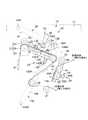
図1及び図2には、本発明に係る接続装置が適用された貼合装置の概略構成図がそれぞれ示されている。ここで、図1には、第1の巻体から帯状体を繰り出す貼合装置の概略構成図が示され、図2には、第2の巻体から帯状体を繰り出す図1と同様の構成図が示されている。これらの図において、貼合装置10は、筐体を形成する正面視方形状のパネル体11を含み、このパネル体11の右側中央部において第1の巻体12を回転可能に保持するとともに、第1の巻体12の左下側に第2の巻体13を回転可能に保持するようになっている。また、貼合装置10は、各巻体12,13の左側に設けられた接続装置15と、この接続装置15の左下側に設けられた貼合手段16とを備えて構成されている。 The schematic block diagram of the bonding apparatus with which the connection apparatus which concerns on this invention was applied is shown by FIG.1 and FIG.2, respectively. Here, FIG. 1 shows a schematic configuration diagram of a laminating apparatus for feeding a belt-like body from the first winding body, and FIG. 2 shows a configuration similar to FIG. 1 for feeding the belt-like body from the second winding body. The figure is shown. In these drawings, the
前記第1及び第2の巻体12,13にそれぞれ巻回される帯状体Mは、図3(A)に示されるように、剥離シートとして作用するベースシートBと、このベースシートBの図3(A)中上面に積層されたエネルギー線硬化型接着層S1と、当該エネルギー線硬化型接着層S1の同図中上面に積層された保護フィルム層S2とからなる。ベースシートB上の各層S1,S2には、内側がラベルLとなる円盤状プリカットC1(図3(B)参照)が所定ピッチで形成され、この円盤状プリカットC1の図3(B)中上下両側に波形プリカットC2が形成されている。前記円盤状プリカットC1と波形プリカットC2との間は、前工程において前記各層S1,S2を取り除いたカス抜き部Dとされる一方、このカス抜き部Dの図3(A)中左右両側に枕部Eが形成され、この枕部Eによってロール状に巻回されたラベルLの押し跡や押し傷を防止するようになっている。 As shown in FIG. 3A, a strip M wound around each of the first and
各ラベルLの面内中央部には、円盤状プリカットC1と略同心円上に丸穴Hがそれぞれ形成され、当該丸穴Hは、帯状体Mを貫通するように形成されている。これにより、ラベルLは、図示しない光ディスク等の記録基板の平面形状、すなわち略ドーナツ形状に対応する形状に形成される。ラベルLは、貼合手段16を介してベースシートBから剥離され、ポリカーボネート等からなるディスク基板(図示省略)の面に貼付される。この状態で、保護フィルム層S2を剥がし、エネルギー線硬化型接着層S1にピット等の微細な凹凸を形成することにより前記記録基板が構成される。なお、前記凹凸は、エネルギー線硬化型接着層S1に対して凹凸面を備えたスタンパ(図示省略)を貼合し、前記ディスク基板側から紫外線を照射して前記樹脂層S1を硬化させた後に当該スタンパを剥離することにより形成される。 A round hole H is formed in the center of the surface of each label L substantially concentrically with the disc-shaped precut C1, and the round hole H is formed so as to penetrate the belt-like body M. Thereby, the label L is formed in a planar shape of a recording substrate such as an optical disk (not shown), that is, a shape corresponding to a substantially donut shape. The label L is peeled off from the base sheet B through the bonding means 16 and attached to the surface of a disk substrate (not shown) made of polycarbonate or the like. In this state, the protective film layer S2 is peeled off, and fine irregularities such as pits are formed on the energy ray curable adhesive layer S1, thereby forming the recording substrate. In addition, after the said unevenness | corrugation bonds the stamper (illustration omitted) provided with the uneven surface with respect to energy-beam curable contact bonding layer S1, and irradiates an ultraviolet-ray from the said disk substrate side, the said resin layer S1 is hardened. It is formed by peeling off the stamper.
図3(C)に示されるように、第1及び第2の巻体12,13における帯状体Mの各終端12a,13a側には、片状の連結シートM1がそれぞれ設けられ、当該連結シートM1は、裏面側(図中下面側)に再接着可能な接着剤からなる接着層を備えている。連結シートM1は、前記終端12a,13aを境界位置として略半分領域が帯状体Mに貼付される一方、残りの略半分領域が巻体12,13の芯部18に貼付されている。なお、図3(D)に示されるように、第1及び第2の巻体12,13において、帯状体Mの終端12a,13aと当該終端12a,13aに最も近接する丸穴Hとの離間距離Xは、所定の長さに設定されている。また、リード端12b,13bと当該リード端12b,13bに最も近接する丸穴Hとの離間距離Yも、所定の長さに設定されている。 As shown in FIG. 3C, a strip-like connecting sheet M1 is provided on each
前記接続装置15は、図1及び図2に示されるように、前記パネル体11の上部中央位置に設けられた繰出手段21と、この繰出手段21と第1及び第2の巻体12,13との間に設けられた接続手段22とを備えて構成されている。 As shown in FIGS. 1 and 2, the connecting
前記繰出手段21は、パネル体11の裏面側に設けられたモーター24と、このモーター24の出力軸に固定されたドライブローラー25と、このドライブローラー25の外周における上部側に設けられたピンチローラー26とを備え、モーター24の回転によって帯状体Mを貼合手段16側に順次繰り出しするようになっている。 The feeding means 21 includes a
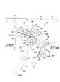
前記接続手段22は、図4及び図5に示されるように、第1の巻体12における帯状体Mのリード端12b側領域(図5参照)を保持可能な第1の保持手段28と、第2の巻体13における帯状体Mのリード端13b側領域(図4参照)を保持可能な第2の保持手段29と、前記ドライブローラー25の右側隣接位置に設けられるとともに、帯状体Mを下面側から支持可能な受け台31と、この受け台31と前記各保持手段28,29の後述する保持部35,135との間に設けられた圧着手段32と、この圧着手段32の左右両側に設けられたセンサ33とを備えて構成されている。 As shown in FIGS. 4 and 5, the connecting
前記第1の保持手段28は、前記リード端12b側領域を保持可能な吸着面35Aを有する保持部35と、この保持部35を回動可能に支持するとともに、前記パネル体11を貫通する回転軸36と、この回転軸36にパネル体11の裏側に位置するアーム38を介して連結されたシリンダ39と、前記吸着面35A上の帯状体Mの位置決めを行う位置決め部40とを備え、シリンダ39のロッド39Aを進退させることで保持部35を図4に示される繰出位置と図5に示される待機位置との間で回転移動させるようになっている。 The first holding means 28 has a holding
前記保持部35は、吸着面35A側に多数のバキューム穴(図示省略)が形成されている一方、吸着面35Aと反対側でホース等を介して吸気機構(図示省略)に接続されている。また、吸着面35Aと回転軸36との間及び回転軸36の外周側には、ガイドローラー41,42がそれぞれ設けられ、これらガイドローラー41,42により第1の巻体12から吸着面35A側へ帯状体Mの繰り出しが案内される。また、保持部35は、前記繰出位置で吸着面35Aが受け台31の上面と略同一面上に位置する一方、前記待機位置で第2の巻体13から繰り出される帯状体Mに非干渉となる位置に設定されている。 The holding
前記シリンダ39は、前記パネル本体11の裏面側に位置して前記ロッド39Aを支持するシリンダ本体44を備えて構成されている。シリンダ本体44は、その基端側(左端側)においてピボット44Aを介してパネル本体11に支持されており、先端側(右端側)が上下に揺動するように回動可能となっている。また、ロッド39Aは、先端側が前記アーム38にヒンジ38Aを介して連結され、アーム38と相対回動可能に設けられている。 The
前記位置決め部40は、図5に示されるように、リード端12b側の一番始めのラベルLの丸穴Hに挿入可能な位置決めピン40Aと、この位置決めピン40Aを吸着面35Aから出没させる位置決めシリンダ40Bとを備えて構成されている。位置決めピン40Aは、吸着面35Aがリード端12b側領域を保持した状態で、吸着面35Aから突出して前記丸穴Hに係合し、リード端12bの位置決めを行う。これにより、位置決めが行われたリード端12bが吸着面35Aの所定位置にセットされるとともに、保持部35の回動時にリード端12b側領域の位置ずれを回避するようになっている。また、位置決めピン40Aは、第1及び第2の巻体12,13の帯状体Mの接続が終了して当該帯状体Mの繰り出しを開始する直前に、吸着面35Aの吸着解除と略同時に当該吸着面35Aから埋没するようになっている。 As shown in FIG. 5, the positioning
前記第2の保持手段29は、第1の保持手段28と類似した構成を備えており、第1の保持手段28の各部の向きを変えるように設けられている。従って、第2の保持手段29側の各部について、第1の保持手段28側の各部と同一部分については、第1の保持手段28側で用いた二桁の参照符号を下二桁に含む100番台の符号で示すこととし、重複する構造部分に関する説明を省略する。 The second holding means 29 has a configuration similar to that of the first holding means 28 and is provided so as to change the direction of each part of the first holding means 28. Therefore, for each part on the second holding means 29 side, the same part as each part on the first holding means 28 side includes the two-digit reference numerals used on the first holding means 28 side in the last two digits 100. The description will be omitted with reference to the reference numerals and overlapping structural parts.
第2の保持手段29において保持部135は、図4に示されるように、第2の巻体13の帯状体Mのリード端13b側領域を保持可能な吸着面135Aを備え、シリンダ139のロッド139Aを進退させることにより、図4に示される待機位置と図5に示される繰出位置との間で回動可能に設けられている。保持部135の回転軸136と反対側には、ガイドローラー141が設けられ、当該ガイドローラー141と第2の巻体13との間に位置する二つの補助ローラー46,47に帯状体Mが案内され、当該帯状体Mが吸着面135A上に位置するようになっている。また、保持部135は、前記繰出位置で吸着面135Aが受け台31の上面と略同一面上、すなわち、第1の保持手段28における吸着面35Aの繰出位置と略同じ位置に設定される一方、前記待機位置で第1の巻体12から繰り出される帯状体Mに非干渉となる位置に設定される。つまり、第2の保持部135Aの吸着面135Aは、第1の保持部35の吸着面35Aと交互に前記受け台31の上面と同一面上に位置するようになっている。なお、シリンダ139は、ピボット144Aを介して先端側(上端側)が左右に揺動するように回動可能となっている。As shown in FIG. 4, in the
前記受け台31は、帯状体Mを支持する面(上面)側に多数のバキューム穴(図示省略)が形成された吸着面を備え、帯状体Mを吸着保持可能となっている一方、帯状体Mの繰り出し時に、前記吸着を解除して帯状体Mの繰り出しのガイドして作用するようになっている。 The
前記圧着手段32は、パネル本体11に支持されるシリンダにより構成される圧着手段本体49と、この圧着手段本体49の下端側に連結されるとともに、前記連結シートM1より大きい押圧面を有する押圧板51とを備えて構成されている。圧着手段32は、受け台31と吸着面35A(図4参照、図5では吸着面135A)との間に跨る帯状体Mの表面(上面)側に、押圧板51を介して押し付け力を付与可能に設けられている。 The pressure-bonding means 32 is connected to a pressure-bonding means
前記センサ33は、受け台31の上方に配置されて帯状体Mの前記丸穴Hを検出する穴検出センサ53と、吸着面35A(図4参照、図5では吸着面135A)の上方に配置されて帯状体Mの終端12a,13aを検出する終端検出センサ54とからなる。前記各検出センサ53,54の検出データは、図示しない制御装置に出力され、当該制御装置によって繰出手段21のモーター24の駆動を制御するようになっている。 The
前記貼合手段16は、図1に示されるように、パネル体11に固定されたピールプレート56と、このピールプレート56の上方に設けられた吸着部材57と、この吸着部材57の一端側(左端側)に設けられた貼合ローラー58と、吸着部材57を下側から支持するとともに、吸着部材57の位置を略水平位置と傾斜位置との間で変位させるシリンダ部材60Aを含む姿勢変位手段60と、この姿勢変位手段60を左右方向に移動させる移動手段61とを備えて構成されている。 As shown in FIG. 1, the bonding means 16 includes a
前記ピールプレート56は、ブァッファ部62及び複数のローラー63を経由して貼合手段16側に送り出された帯状体MのラベルLを剥離可能に設けられている。すなわち、帯状体Mは、ピールプレート56の先端(左端)で急激に反転するように巻き掛けられており、当該ピールプレート56の先端位置でラベルLが略水平面内の左方に剥離可能となっている。ここで、ブァッファ部62を構成するローラー62Aは上下移動可能に設けられている。なお、ラベルLが剥離された帯状体Mは、貼合手段16の右側に位置するドライブローラー64Aとピンチローラ−64Bに挟持搬送されるとともに、複数のローラー64Cを介して繰り出され、最終的に、パネル体11の下側に位置する図示しない回収箱に回収される。 The
前記吸着部材57は、ピールプレート56によって剥離されたラベルLを上面側から吸着可能に設けられているとともに、前記移動手段61を介して図示しないテーブル上に配置された前述のディスク基板上に移動可能に設けられている。また、貼合ローラー58は、前記ディスク基板上を回転しながら所定の押圧力を付与可能に設けられている。これを更に詳述すると、ラベルLと前記ディスク基板とが位置を合わせされた状態で、姿勢変位手段60を介して吸着部材57の貼合ローラー58側が低くなるような傾斜姿勢としつつ、吸着部材57を移動させることにより、貼合ローラー58が前記ディスク基板上を回転して吸着部材57からラベルLを前記ディスク基板上に貼合するようになっている。 The adsorbing
なお、図1及び図2中、符号65,66は、センサであり、これらセンサ65,66は第1及び第2の巻体12,13を挟み込む位置にそれぞれ設けられるとともに、各巻体12,13の帯状体Mの終端12a,13aを検出し、当該終端12a,13aが検出された巻体の次に繰り出される巻体がセットされているか否かを検出する。仮に、次に繰り出される巻体がセットされていない場合、装置全体の作動を停止させ、図示しない警報等によりオペレーターに知らせるようになっている。 1 and 2,
次に、接続装置15における第1及び第2の巻体12,13の帯状体Mの接続手順について説明する。 Next, a procedure for connecting the strips M of the first and second winding
ここでは、図4に示されるように、第1の保持手段28の保持部35が前記繰出位置に設定されるとともに、第2の保持手段29の保持部135が前記待機位置に設定され、第1の巻体12における帯状体Mが第1の保持手段28の保持部35、受け台31上を経由して繰出手段21を通過するように掛け回される。この状態で、保持部35及び受け台31の吸着は解除されており、ドライブローラー25のモーター24が駆動することによって第1の巻体12の帯状体Mが繰り出される。また、第2の巻体13の帯状体Mは、各補助ローラー46,47に掛け回されるとともに、リード端13b側における一番始めのラベルLの丸穴Hを位置決めピン140Aに係合して位置決めすると、リード端13bと吸着面135Aの図4中上端とが略一致した状態になり、リード端13b側領域が吸着面135Aに吸着保持されている。 Here, as shown in FIG. 4, the holding
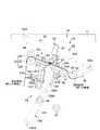
第1の巻体12から帯状体Mの繰り出しを行って当該帯状体Mの巻回残量がなくなると、帯状体Mの終端12a側に設けられた前記連結シートM1が前記モーター24の駆動力によって第1の巻体12の芯部18から剥がされる。この状態から更に繰り出しを行い、保持部35の吸着面35A上を帯状体Mの終端12aが通過するときに、当該終端12aを終端検出センサ54が検出する。この検出を終えた後に、穴検出センサ53が終端12aに最も近い丸穴Hを検出すると、当該検出データによりモーター24の駆動量を調整し、図6に示されるように、帯状体Mの終端12aが受け台31の保持部35側端部(右端部)に到達したときに、帯状体Mの繰り出しを停止する。これにより、受け台31の右端から連結シートM1がはみ出る状態となり、この状態において帯状体Mの終端12a側領域が受け台31の吸着面により吸着保持される。なお、受け台31上における帯状体Mの繰り出しが停止中であっても、ブァッファ部62により当該ブァッファ部62より下位における帯状体Mの繰り出しが停止することはない。 When the belt-like body M is unwound from the first winding
その後、第1の保持手段28におけるシリンダ39のロッド39Aを後退させることにより、アーム38を介して保持部35が反時計回りに回動し、図7に示されるように、保持部35が受け台31から大きく離間した前記待機位置に移動する。 Thereafter, by retracting the
次いで、第2の保持手段29におけるシリンダ139のロッド139Aを前進させ、アーム138を介して保持部135を反時計回りに回動させる。これにより、図8に示されるように、保持部135が前記繰出位置に設定され、保持部135の吸着面135Aが受け台31の吸着面と略同一面上に位置するとともに、第2の巻体13における帯状体Mのリード端13bが第1の巻体12における帯状体Mの終端12aとが突き合う位置合わせが行われ、リード端13b側領域が連結シートM1と重なる状態となる。そして、圧着手段32の押圧板51を受け台31及び保持部135に向かって押し付けることにより、前記リード端13b側領域に連結シートM1のはみ出した領域が貼付され、第1の巻体12における帯状体Mの終端12a側領域と第2の巻体13における帯状体Mのリード端13b側領域が接続される。 Next, the
前記接続が完了すると、受け台31及び保持部135による帯状体Mの吸着を解除するとともに、位置決めシリンダ140Bを後退させて位置決めピン140Aを吸着面135Aから埋没させ、モーター24を駆動して第2の巻体13の帯状体Mを繰り出すことが可能となる(図5参照)。この繰り出しを行っている間に、第1の巻体12を新しいものと交換し、第1の巻体12のリード端12b側における一番始めのラベルLの丸穴Hを位置決めピン40Aに係合すると、リード端12bが吸着面35Aの下端に略一致した状態となって位置決めされ、第1の巻体12のリード端12b側領域が第1の保持手段28の保持部35に保持される。 When the connection is completed, the suction of the band M by the
そして、図9に示されるように、第2の巻体13から帯状体Mの繰り出しを終えると、前述した第1の巻体12と同様にして、第2の巻体13における帯状体Mの終端13a側領域が受け台31の吸着面に保持される。この後、第2の保持手段29におけるロッド139Aを後退させて保持部135を時計回りに回動し、図10に示されるように、保持部135を前記待機位置に復帰させる。 Then, as shown in FIG. 9, when the feeding of the band-shaped body M from the
次いで、第1の保持手段28のロッド39Aを前進させ、保持部35を時計回りに回動させることにより、図11に示されるように、保持部35を前記繰出位置に復帰させる。これにより、第1の巻体12における帯状体Mのリード端12bが第2の巻体13における帯状体Mの終端13aと突き合わされ、リード端12b側領域が連結シートM1と重なる状態となる。この状態で、圧着手段32を介して前述と同様に、第1の巻体12における帯状体Mのリード端12b側領域と第2の巻体13における帯状体Mの終端13a側領域とが接続される。 Next, the
以上の手順を繰り返し行うことにより、第1及び第2の巻体12,13から帯状体Mを順次繰り出すことが可能となる。 By repeating the above procedure, the belt-like body M can be sequentially fed out from the first and second winding
従って、このような実施の形態によれば、帯状体Mの終端12a,13a側に再接着可能な接着層を有する連結シートM1を設けたから、当該連結シートM1を利用して第1及び第2の巻体12,13の各帯状体Mを迅速に接続することができる。しかも、第1及び第2の保持手段28,29と受け台31とにより、一方の巻体12,13の終端12a,13aと、他方の巻体12,13のリード端12b,13bとを突き合わせる位置合わせが行われるので、各巻体12,13の終端12a,13a側やリード端12b,13b側を切断する工程が不要となり、当該切断のための装置やカス回収機構等を省略して、装置全体の小型化、簡素化を達成することが可能となる他、ラベルLを最後まで利用することができ、ラベルLの無駄をなくすことができる。 Therefore, according to such an embodiment, since the connecting sheet M1 having the adhesive layer that can be re-adhered is provided on the terminal ends 12a and 13a side of the belt-like body M, the first and second elements are utilized using the connecting sheet M1. The strips M of the winding
本発明を実施するための最良の構成、方法などは、以上の記載で開示されているが、本発明は、これに限定されるものではない。
すなわち、本発明は、主に特定の実施の形態に関して特に図示し、且つ、説明されているが、本発明の技術的思想及び目的の範囲から逸脱することなく、以上に述べた実施の形態に対し、形状、材料、数量、その他の詳細な構成において、当業者が様々な変形を加えることができるものである。The best configuration, method and the like for carrying out the present invention have been disclosed in the above description, but the present invention is not limited to this.
That is, the invention has been illustrated and described with particular reference to particular embodiments, but it should be understood that the above-described embodiments are not deviated from the technical idea and scope of the invention. On the other hand, those skilled in the art can make various modifications in shape, material, quantity, and other detailed configurations.
例えば、前述した実施形態の構成に加え、各巻体12,13の交換時に、これらの帯状体Mのリード端12b,13b側を把持し、当該リード端12b,13b側領域を吸着面35A,135Aに保持させるアームやロボット等を設けてもよい。 For example, in addition to the configuration of the above-described embodiment, when replacing the respective winding
また、前記帯状体Mとしては、ベースシートBにラベルLが積層される構成の他に、ラベルLのない帯材や帯状シート等の他の帯状体を適用することもできる。 In addition to the configuration in which the label L is laminated on the base sheet B, other belt-like bodies such as a belt material without the label L and a belt-like sheet can also be applied as the belt-like body M.
本発明は、主に、複数の巻体から順次繰り出される帯状体を用いる貼合装置等に利用される。 INDUSTRIAL APPLICATION This invention is mainly utilized for the bonding apparatus etc. which use the strip | belt-shaped body drawn | fed out sequentially from several rolls.
12 第1の巻体
12a 終端
12b リード端
13 第2の巻体
13a 終端
13b リード端
15 接続装置
21 繰出手段
22 接続手段
M 帯状体
M1 連結シート12
Claims (2)
Translated fromJapanese前記接続手段は、前記第1の巻体の帯状体のリード端側部分を保持可能な吸着面を有する保持部を備えた第1の保持手段と、前記第2の巻体の帯状体のリード端側部分を保持可能な吸着面を有する保持部を備えた第2の保持手段と、第1及び第2の巻体の帯状体を保持する受け台と、当該受け台と前記第1、第2の保持手段との間に設けられた圧着手段とを含み、前記第1の巻体を保持する保持部の吸着面と、前記第2の巻体を保持する保持部の吸着面は交互に受け台の上面と同一面上に位置し、
一方の巻体からの帯状体の終端が前記受け台の端部に達したときに、当該受け台が前記終端側領域を保持するとともに、前記保持部の何れか一方が、他方の巻体からの帯状体のリード端側を保持して前記受け台の上面と同一面上に位置し、前記保持された終端とリード端とを突き合わせた状態で、前記連結シートを介して圧着手段が圧着力を付与して第1及び第2の巻体の帯状体を接続することを特徴とする帯状体の接続装置。A feeding means provided so that the first and second wound bodies made of a belt-like body to which a substantially half region of theadhesive layer provided on the back surface side of the piece-like connecting sheet is attached to the terminal side can be successively delivered; A connection means for connecting the terminal side region of the band of the body and the lead end side region of the band of the other wound body,
The connection meansincludes a first holding meanshaving a holding portion having a suction surface capable of holding a lead end side portion of the belt-like body of the first winding body, and a lead of the belt-like body of the second winding body. A second holding meanshaving a holding portion having a suction surface capable of holding the end side portion; a cradle for holding the belt-like body of the first and second wound bodies; the cradle and the first and first A holding means for holdingthe first winding body, and an adsorption surface of the holding section for holding the second winding body alternately. Located on the same plane as the upper surface of the cradle,
When the end of the belt-like body from one winding body reaches the end of the cradle, the cradle holds the terminal side region, andeither one of the holding parts is separated from the other winding body. of holding the lead end side of the strip located on the same surface as the cradle upper surface it said, abutted theend and rie deend the held, crimping means via the connecting sheet A connecting device for a band-shaped body, wherein a band-shaped body of the first and second wound bodies is connected by applying a crimping force.
前記接続手段は、前記第1の巻体の帯状体のリード端側部分を保持可能な吸着面を有する保持部を備えた第1の保持手段と、前記第2の巻体の帯状体のリード端側部分を保持可能な吸着面を有する保持部を備えた第2の保持手段と、第1及び第2の巻体の帯状体を保持する受け台と、当該受け台と前記第1、第2の保持手段との間に設けられた圧着手段とを含み、前記第1の巻体を保持する保持部の吸着面と、前記第2の巻体を保持する保持部の吸着面は交互に受け台の上面と同一面上に位置し、
一方の巻体からの帯状体の終端が前記受け台の端部に達したときに、当該受け台が前記終端側領域を保持するとともに、前記保持部の何れか一方が、他方の巻体からの帯状体のリード端側を保持し、
前記保持された終端とリード端とを突き合わせ、
次いで、前記連結シートを介して圧着手段が圧着力を付与して第1及び第2の巻体の帯状体を接続することを特徴とする帯状体の接続方法。A feeding means provided so that the first and second wound bodies made of a belt-like body to which a substantially half region of theadhesive layer provided on the back surface side of the piece-like connecting sheet is attached to the terminal side can be successively delivered; Using a connection means for connecting the terminal side region of the band of the body and the lead end region of the band of the other wound body,
The connection meansincludes a first holding meanshaving a holding portion having a suction surface capable of holding a lead end side portion of the belt-like body of the first winding body, and a lead of the belt-like body of the second winding body. A second holding meanshaving a holding portion having a suction surface capable of holding the end side portion; a cradle for holding the belt-like body of the first and second wound bodies; the cradle and the first and first A holding means for holdingthe first winding body, and an adsorption surface of the holding section for holding the second winding body alternately. Located on the same plane as the upper surface of the cradle,
When the end of the belt-like body from one winding body reaches the end of the cradle, the cradle holdsthe terminal side region, andeither one of the holding parts is separated from the other winding body. Hold the lead end of the belt
Butt a terminationand rie de end the retained,
Next, the strip-shaped body connecting method, wherein the crimping means applies a crimping force through the connecting sheet to connect the strips of the first and second wound bodies.
Priority Applications (7)
| Application Number | Priority Date | Filing Date | Title |
|---|---|---|---|
| JP2003316504AJP4170181B2 (en) | 2003-09-09 | 2003-09-09 | Belt-like body connection device and connection method |
| GB0418012AGB2405866B (en) | 2003-09-09 | 2004-08-12 | Connecting apparatus and connecting method of web material |
| TW093125020ATW200524786A (en) | 2003-09-09 | 2004-08-19 | Connecting apparatus and connecting method of web material |
| NL1026891ANL1026891C2 (en) | 2003-09-09 | 2004-08-20 | Connection device and connection method for material supplied on a roll. |
| AT0145904AAT500401B1 (en) | 2003-09-09 | 2004-08-31 | CONNECTING DEVICE AND CONNECTION METHOD FOR A ROLLER MATERIAL |
| US10/935,281US7138033B2 (en) | 2003-09-09 | 2004-09-08 | Connecting apparatus and connecting method of web material |
| CNB2004100770050ACN100457590C (en) | 2003-09-09 | 2004-09-09 | Connecting apparatus and connecting method of web material |
Applications Claiming Priority (1)
| Application Number | Priority Date | Filing Date | Title |
|---|---|---|---|
| JP2003316504AJP4170181B2 (en) | 2003-09-09 | 2003-09-09 | Belt-like body connection device and connection method |
Publications (2)
| Publication Number | Publication Date |
|---|---|
| JP2005082329A JP2005082329A (en) | 2005-03-31 |
| JP4170181B2true JP4170181B2 (en) | 2008-10-22 |
Family
ID=33028457
Family Applications (1)
| Application Number | Title | Priority Date | Filing Date |
|---|---|---|---|
| JP2003316504AExpired - Fee RelatedJP4170181B2 (en) | 2003-09-09 | 2003-09-09 | Belt-like body connection device and connection method |
Country Status (7)
| Country | Link |
|---|---|
| US (1) | US7138033B2 (en) |
| JP (1) | JP4170181B2 (en) |
| CN (1) | CN100457590C (en) |
| AT (1) | AT500401B1 (en) |
| GB (1) | GB2405866B (en) |
| NL (1) | NL1026891C2 (en) |
| TW (1) | TW200524786A (en) |
Families Citing this family (23)
| Publication number | Priority date | Publication date | Assignee | Title |
|---|---|---|---|---|
| JP4672340B2 (en) | 2003-11-27 | 2011-04-20 | ティー・エヌ・エー オーストラリア ピィー・ティー・ワイ リミテッド | Film bonding machine |
| AU2004231198B2 (en)* | 2003-11-27 | 2009-10-08 | Tna Australia Pty Limited | A film splicing machine |
| JP2005292427A (en)* | 2004-03-31 | 2005-10-20 | Sato Corp | Label paper, label sticking device, and label paper supply method to label sticking device |
| US20080135158A1 (en)* | 2004-05-14 | 2008-06-12 | Impresstik Machinery Pty Ltd | Feeding Webs for Processing and Removing Webs |
| FI118894B (en)* | 2006-03-20 | 2008-04-30 | Metso Paper Inc | Procedure in connection with a roller cutting machine |
| JP5196652B2 (en)* | 2008-11-28 | 2013-05-15 | 四国化工機株式会社 | Sealing tape bonding device |
| US8167017B2 (en)* | 2009-11-13 | 2012-05-01 | Pitney Bowes Inc. | Multi-mode system for dispensing adhesive-backed labels |
| US8047250B2 (en)* | 2009-11-23 | 2011-11-01 | Pitney Bowes Inc. | Postage label dispensing system and repositionable peeler guide therefor |
| IT1397685B1 (en)* | 2010-01-15 | 2013-01-18 | Sacmi Labelling S P A Ora Sacmi Verona S P A | UNBINDING GROUP, PARTICULARLY FOR LABELING DEVICES |
| JP2012035925A (en)* | 2010-08-03 | 2012-02-23 | Sumitomo Heavy Industries Modern Ltd | Web butt splicing device |
| CN102225726A (en)* | 2011-04-14 | 2011-10-26 | 汕头东风印刷股份有限公司 | Connecting structure between splicing joints of two transfer composite sheet rolls and manufacturing method thereof |
| JP5755069B2 (en)* | 2011-07-29 | 2015-07-29 | ユニ・チャーム株式会社 | Shape-retaining material supply apparatus and method |
| CN102367002B (en)* | 2011-10-24 | 2013-06-12 | 南通市通州区宝田电器机械制造有限公司 | Sheet overlapping device used for all-plastic hose cementing machining |
| EP2941111B1 (en)* | 2012-12-27 | 2017-03-08 | Fuji Machine Mfg. Co., Ltd. | Splicing device and splicing-tape detection method |
| ITVR20140052A1 (en)* | 2013-07-16 | 2015-01-17 | Sacmi Verona Spa | Labeling machine for labeling of products to be labeled |
| JP6322284B2 (en)* | 2014-06-30 | 2018-05-09 | 株式会社瑞光 | Sheet feeding system and sheet feeding method using the same |
| JP6789018B2 (en)* | 2016-07-13 | 2020-11-25 | リンテック株式会社 | Long body connection device and connection method |
| US10457512B2 (en) | 2016-09-19 | 2019-10-29 | New Era Converting Machinery, Inc. | Automatic lapless butt material splice |
| KR101827204B1 (en) | 2017-03-13 | 2018-02-07 | 주식회사 신한정공 | Apparatus for unwinding and supplying sheet from sheet-roll |
| JP7236719B2 (en)* | 2018-10-04 | 2023-03-10 | 株式会社イシダ | bag making and packaging machine |
| JP7245491B2 (en)* | 2018-10-04 | 2023-03-24 | 株式会社イシダ | bag making and packaging machine |
| US10953646B2 (en) | 2018-10-26 | 2021-03-23 | ACCO Brands Corporation | Laminating system with coded film cartridge |
| WO2021129077A1 (en)* | 2019-12-24 | 2021-07-01 | 无锡先导智能装备股份有限公司 | Automatic roll replacing device, and winding equipment |
Family Cites Families (20)
| Publication number | Priority date | Publication date | Assignee | Title |
|---|---|---|---|---|
| USRE29365E (en)* | 1972-10-24 | 1977-08-23 | Butler Automatic, Inc. | Web supply apparatus |
| JPS6045096B2 (en)* | 1979-07-05 | 1985-10-07 | 富士写真フイルム株式会社 | Tape joining equipment |
| JPS59117763A (en)* | 1982-12-24 | 1984-07-07 | Fuji Photo Film Co Ltd | Magnetic tape cutting and jointing method |
| JPS59194961A (en)* | 1983-04-14 | 1984-11-05 | Tokyo Jushi Sangyo Kk | Sheet feeding device |
| DE3439313C2 (en)* | 1984-10-26 | 1994-07-07 | Focke & Co | Device for joining webs of packaging material |
| JPS63162434A (en) | 1986-12-25 | 1988-07-06 | 株式会社 東京自働機械製作所 | Exchanger for packaging material in packaging-material delivery device |
| DE4016578A1 (en)* | 1990-05-23 | 1991-11-28 | Winkler Duennebier Kg Masch | DEVICE FOR JOINING MATERIAL RAILS |
| US5388387A (en)* | 1993-03-12 | 1995-02-14 | Kliklok Corporation | Packaging film feeding and splicing apparatus and method |
| JPH08108957A (en) | 1994-10-07 | 1996-04-30 | Shikoku Kakoki Co Ltd | Tape connecting device |
| JP2873182B2 (en)* | 1995-03-17 | 1999-03-24 | ソマール株式会社 | Method and apparatus for continuously feeding raw film in a film sticking apparatus |
| DE19529866B4 (en)* | 1995-08-14 | 2007-01-11 | Ralf Jetter | Method for automatic splicing of two self-adhesive adhesive label coated label tapes and apparatus for carrying out the method |
| US5660675A (en)* | 1995-10-19 | 1997-08-26 | Transprint Usa | Method and apparatus for splicing heat transfer printing paper |
| DE19607495B4 (en)* | 1996-02-28 | 2005-04-28 | Heiber & Schroeder Maschb Gmbh | Method and device for automatically changing and connecting film rolls in the production of folding boxes with film windows |
| CN2288028Y (en)* | 1996-08-06 | 1998-08-19 | 机械工业部西安重型机械研究所 | Metal strip sewing machine |
| US5855714A (en)* | 1996-09-09 | 1999-01-05 | Bockh; Mat G. | Roll splicing system and method |
| US6331222B1 (en)* | 1997-11-06 | 2001-12-18 | Asterisk, Inc. | Splicer for joining thin sheets |
| DE19901026A1 (en)* | 1999-01-13 | 2000-07-20 | Jagenberg Papiertech Gmbh | Method and device for connecting material webs |
| JP2001233514A (en)* | 2000-02-23 | 2001-08-28 | Shikoku Kakoki Co Ltd | Device and method for splicing roll film |
| JP4031211B2 (en) | 2001-05-08 | 2008-01-09 | リンテック株式会社 | Device for connecting strips |
| US6817566B2 (en)* | 2002-10-30 | 2004-11-16 | Butler Automatic, Inc. | Web splicer |
- 2003
- 2003-09-09JPJP2003316504Apatent/JP4170181B2/ennot_activeExpired - Fee Related
- 2004
- 2004-08-12GBGB0418012Apatent/GB2405866B/ennot_activeExpired - Fee Related
- 2004-08-19TWTW093125020Apatent/TW200524786A/ennot_activeIP Right Cessation
- 2004-08-20NLNL1026891Apatent/NL1026891C2/ennot_activeIP Right Cessation
- 2004-08-31ATAT0145904Apatent/AT500401B1/ennot_activeIP Right Cessation
- 2004-09-08USUS10/935,281patent/US7138033B2/ennot_activeExpired - Lifetime
- 2004-09-09CNCNB2004100770050Apatent/CN100457590C/ennot_activeExpired - Fee Related
Also Published As
| Publication number | Publication date |
|---|---|
| US7138033B2 (en) | 2006-11-21 |
| CN100457590C (en) | 2009-02-04 |
| AT500401A2 (en) | 2005-12-15 |
| AT500401B1 (en) | 2007-03-15 |
| TW200524786A (en) | 2005-08-01 |
| JP2005082329A (en) | 2005-03-31 |
| AT500401A3 (en) | 2006-03-15 |
| NL1026891C2 (en) | 2005-11-30 |
| CN1594051A (en) | 2005-03-16 |
| US20050051257A1 (en) | 2005-03-10 |
| TWI314119B (en) | 2009-09-01 |
| GB2405866B (en) | 2006-08-09 |
| NL1026891A1 (en) | 2005-03-10 |
| GB2405866A (en) | 2005-03-16 |
| GB0418012D0 (en) | 2004-09-15 |
Similar Documents
| Publication | Publication Date | Title |
|---|---|---|
| JP4170181B2 (en) | Belt-like body connection device and connection method | |
| KR100915259B1 (en) | Protective tape applying and separating methods | |
| TWI466185B (en) | Peeling device of a protection tape | |
| JP5261522B2 (en) | Pasting device and pasting method | |
| TW200302520A (en) | Protective tape applying method and apparatus, and protective tape separating method | |
| KR20110050647A (en) | Mounting apparatus and mounting method | |
| JP2004134020A (en) | Laminating device | |
| JP4801016B2 (en) | Sheet sticking device and sticking method | |
| WO2006001289A1 (en) | Sheet peeling device and method | |
| WO2006057376A1 (en) | Treatment device for fragile member | |
| JP2003151181A (en) | Optical disk sticking device | |
| JP2007320678A (en) | Method and apparatus for peeling outer layer body | |
| JP5572045B2 (en) | Sheet sticking device and sticking method | |
| JP2009073645A (en) | Adhesive tape applying device and tape remaining amount detection method | |
| WO2011121646A1 (en) | Method and apparatus for stripping cover film | |
| CN113387211B (en) | Winding device and winding method | |
| JP5586093B2 (en) | Sheet sticking device and sticking method | |
| JP2002362524A (en) | Automatic labeling device | |
| JP2003175922A (en) | Automatic labeling device | |
| JP6030909B2 (en) | Sheet sticking device and sheet sticking method | |
| JPH0940267A (en) | Product identification tape sticking device and sticking method | |
| WO2011115172A1 (en) | Sheet cutting method and sheet cutting device | |
| JP2022135042A (en) | Sheet sticking device and sheet sticking method | |
| JP2005022676A (en) | Labeling method and apparatus | |
| JP3529197B2 (en) | Sheet material bonding method and apparatus |
Legal Events
| Date | Code | Title | Description |
|---|---|---|---|
| A621 | Written request for application examination | Free format text:JAPANESE INTERMEDIATE CODE: A621 Effective date:20060529 | |
| A977 | Report on retrieval | Free format text:JAPANESE INTERMEDIATE CODE: A971007 Effective date:20080129 | |
| A131 | Notification of reasons for refusal | Free format text:JAPANESE INTERMEDIATE CODE: A131 Effective date:20080205 | |
| A521 | Request for written amendment filed | Free format text:JAPANESE INTERMEDIATE CODE: A523 Effective date:20080328 | |
| A131 | Notification of reasons for refusal | Free format text:JAPANESE INTERMEDIATE CODE: A131 Effective date:20080422 | |
| A521 | Request for written amendment filed | Free format text:JAPANESE INTERMEDIATE CODE: A523 Effective date:20080618 | |
| TRDD | Decision of grant or rejection written | ||
| A01 | Written decision to grant a patent or to grant a registration (utility model) | Free format text:JAPANESE INTERMEDIATE CODE: A01 Effective date:20080729 | |
| A01 | Written decision to grant a patent or to grant a registration (utility model) | Free format text:JAPANESE INTERMEDIATE CODE: A01 | |
| A61 | First payment of annual fees (during grant procedure) | Free format text:JAPANESE INTERMEDIATE CODE: A61 Effective date:20080806 | |
| FPAY | Renewal fee payment (event date is renewal date of database) | Free format text:PAYMENT UNTIL: 20110815 Year of fee payment:3 | |
| R150 | Certificate of patent or registration of utility model | Ref document number:4170181 Country of ref document:JP Free format text:JAPANESE INTERMEDIATE CODE: R150 Free format text:JAPANESE INTERMEDIATE CODE: R150 | |
| FPAY | Renewal fee payment (event date is renewal date of database) | Free format text:PAYMENT UNTIL: 20110815 Year of fee payment:3 | |
| FPAY | Renewal fee payment (event date is renewal date of database) | Free format text:PAYMENT UNTIL: 20120815 Year of fee payment:4 | |
| R250 | Receipt of annual fees | Free format text:JAPANESE INTERMEDIATE CODE: R250 | |
| FPAY | Renewal fee payment (event date is renewal date of database) | Free format text:PAYMENT UNTIL: 20120815 Year of fee payment:4 | |
| FPAY | Renewal fee payment (event date is renewal date of database) | Free format text:PAYMENT UNTIL: 20130815 Year of fee payment:5 | |
| R250 | Receipt of annual fees | Free format text:JAPANESE INTERMEDIATE CODE: R250 | |
| R250 | Receipt of annual fees | Free format text:JAPANESE INTERMEDIATE CODE: R250 | |
| R250 | Receipt of annual fees | Free format text:JAPANESE INTERMEDIATE CODE: R250 | |
| R250 | Receipt of annual fees | Free format text:JAPANESE INTERMEDIATE CODE: R250 | |
| R250 | Receipt of annual fees | Free format text:JAPANESE INTERMEDIATE CODE: R250 | |
| R250 | Receipt of annual fees | Free format text:JAPANESE INTERMEDIATE CODE: R250 | |
| R250 | Receipt of annual fees | Free format text:JAPANESE INTERMEDIATE CODE: R250 | |
| R250 | Receipt of annual fees | Free format text:JAPANESE INTERMEDIATE CODE: R250 | |
| LAPS | Cancellation because of no payment of annual fees |