JP4168334B2 - Editing apparatus and editing method - Google Patents
Editing apparatus and editing methodDownload PDFInfo
- Publication number
- JP4168334B2 JP4168334B2JP2003170124AJP2003170124AJP4168334B2JP 4168334 B2JP4168334 B2JP 4168334B2JP 2003170124 AJP2003170124 AJP 2003170124AJP 2003170124 AJP2003170124 AJP 2003170124AJP 4168334 B2JP4168334 B2JP 4168334B2
- Authority
- JP
- Japan
- Prior art keywords
- video
- editing
- audio
- audio data
- edited
- Prior art date
- Legal status (The legal status is an assumption and is not a legal conclusion. Google has not performed a legal analysis and makes no representation as to the accuracy of the status listed.)
- Expired - Fee Related
Links
Images


Classifications
- H—ELECTRICITY
- H04—ELECTRIC COMMUNICATION TECHNIQUE
- H04N—PICTORIAL COMMUNICATION, e.g. TELEVISION
- H04N5/00—Details of television systems
- H04N5/76—Television signal recording
- H04N5/91—Television signal processing therefor
- G—PHYSICS
- G11—INFORMATION STORAGE
- G11B—INFORMATION STORAGE BASED ON RELATIVE MOVEMENT BETWEEN RECORD CARRIER AND TRANSDUCER
- G11B27/00—Editing; Indexing; Addressing; Timing or synchronising; Monitoring; Measuring tape travel
- G11B27/10—Indexing; Addressing; Timing or synchronising; Measuring tape travel
- G11B27/34—Indicating arrangements
- G—PHYSICS
- G11—INFORMATION STORAGE
- G11B—INFORMATION STORAGE BASED ON RELATIVE MOVEMENT BETWEEN RECORD CARRIER AND TRANSDUCER
- G11B20/00—Signal processing not specific to the method of recording or reproducing; Circuits therefor
- G11B20/10—Digital recording or reproducing
- G—PHYSICS
- G11—INFORMATION STORAGE
- G11B—INFORMATION STORAGE BASED ON RELATIVE MOVEMENT BETWEEN RECORD CARRIER AND TRANSDUCER
- G11B27/00—Editing; Indexing; Addressing; Timing or synchronising; Monitoring; Measuring tape travel
- G11B27/02—Editing, e.g. varying the order of information signals recorded on, or reproduced from, record carriers
- G11B27/031—Electronic editing of digitised analogue information signals, e.g. audio or video signals
- G11B27/032—Electronic editing of digitised analogue information signals, e.g. audio or video signals on tapes
Landscapes
- Engineering & Computer Science (AREA)
- Multimedia (AREA)
- Signal Processing (AREA)
- Television Signal Processing For Recording (AREA)
- Management Or Editing Of Information On Record Carriers (AREA)
- Signal Processing For Digital Recording And Reproducing (AREA)
Description
Translated fromJapanese【0001】
【発明の属する技術分野】
本発明は、編集装置及び方法に関し、例えばテレビジョン放送局で用いるオンエアーシステムに適用して好適なものである。
【0002】
【従来の技術】
従来、オンエアーシステムにおいては、取材等により得られた映像音声を編集装置を用いて所望状態に加工編集し、得られた編集された映像音声(以下、これを編集映像音声と呼ぶ)を放送用のクリップ(映像音声素材)としてサーバに登録することができ、このサーバに登録したクリップを所定のタイミングで読み出して放送することができるようになされている(例えば特許文献1参照)。
【0003】
【特許文献1】
特開平10−285533号公報
【0004】
【発明が解決しようとする課題】
ところで、例えばニュース番組の作成現場では、取材により得られた映像音声を迅速に編集加工して放送することが求められ、特に臨時ニュースの放送時にはより一層の迅速性が要求される。
【0005】
しかしながら、従来のオンエアーシステムに用いられている編集装置は、機能的に映像音声に対する編集加工処理に多くの時間を要し、特に映像に施す特殊効果処理に至ってはリアルタイム以上の速度での処理を行い得ない問題があった。
【0006】
従って、例えばオンエアーシステムに用いられる編集装置において、編集結果を今以上に迅速に得られるようにすることができれば、編集結果の待ち時間を短縮させて、臨時ニュースを放送する際などの緊急時にも今以上に十分な対応を行い得るものと考えられる。
【0007】
本発明は以上の点を考慮したもので、編集結果を迅速に得られる編集装置及び方法を提案しようとするものである。
【0008】
【課題を解決するための手段】
かかる課題を解決するため本発明においては、編集内容を規定したリストに従って編集処理を実行し、得られた編集結果を外部機器に登録する編集装置において、外部機器に登録するモードとして、編集映像音声データの全範囲を登録する全体登録モード又は当該編集映像音声データのうち部分編集すべき部分を登録する部分登録モードのいずれか一方を選択して登録する登録モード選択手段と、リストに従って被編集素材の必要部分に対して映像特殊効果処理又は音声ミキシング処理を施すことによって部分編集映像音声データを生成する部分編集手段と、部分登録モードが選択された場合、部分編集すべき部分のみを読み出し、映像特殊効果処理又は音声ミキシング処理を施した部分編集映像音声データのみを一括して外部機器に登録する一括部分登録モード又は部分編集映像音声データのみを逐次外部機器に登録する逐次部分登録モードのいずれかを選択して部分編集映像音声データを登録する部分登録制御手段とを設けるようにした。
【0009】
この結果、リストに基づく編集映像音声データの全範囲を登録する場合に比べて、編集映像音声データのうち部分編集すべき部分編集映像音声データのみを読み出し、部分編集するため、編集結果を高速に外部機器に登録することができる。
【0010】
また本発明においては、編集方法において、編集内容を規定したリストに従って編集処理を実行し、得られた編集結果を外部機器に登録する編集装置において、外部機器に登録するモードとして、編集映像音声データの全範囲を登録する全体登録モード又は当該編集映像音声データのうち部分編集すべき部分を登録する部分登録モードのいずれか一方を選択して登録する登録モード選択ステップと、リストに従って被編集素材の必要部分に対して映像特殊効果処理又は音声ミキシング処理を施すことによって部分編集映像音声データを生成する部分編集ステップと、部分登録モードが選択された場合、部分編集すべき部分のみを読み出し、映像特殊効果処理又は音声ミキシング処理を施した部分編集映像音声データのみを一括して外部機器に登録する一括部分登録モード又は部分編集映像音声データのみを逐次外部機器に登録する逐次部分登録モードのいずれかを選択して部分編集映像音声データを登録する部分登録制御ステップとを設けるようにした。
【0011】
この結果、この編集方法によれば、リストに基づく編集映像音声データの全範囲を登録する場合に比べて、編集映像音声データのうち部分編集すべき部分編集映像音声データのみを読み出し、部分編集するため、編集結果を高速に外部機器に登録することができる。
【0012】
【発明の実施の形態】
以下図面について、本発明の一実施の形態を詳述する。
【0013】
(1)本実施の形態によるオンエアーシステムの構成
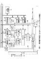
図1において、1は全体としてテレビジョン放送局等に設置される本実施の形態によるオンエアーシステムを示し、取材現場から衛星通信回線等を介して転送され、又は図示しないビデオテープレコーダにより取材テープから再生された140〔Mbps〕程度の解像度を有するHDCAMフォーマット(ソニー株式会社 登録商標)の映像音声データ(以下、これを高解像度映像音声データと呼ぶ)D1をルータ2を介して素材サーバ3及びダウンコンバータ4に入力する。
【0014】
素材サーバ3は、複数のRAID(Redundant Arrays of Independent Disks)から構成される記録再生部を有する大容量のAV(Audio Video)サーバでなり、システム制御部5の制御のもとに、ルータ2を介して供給される一連の高解像度映像音声データD1をファイル化して記憶する。
【0015】
またダウンコンバータ4は、供給される高解像度映像音声データD1を8〔Mbps〕程度の解像度にダウンコンバートすると共に、これをMPEG(Motion Picture Experts Group)フォーマットで圧縮符号化し、かくして得られた低解像度の映像音声データ(以下、これを低解像度映像音声データと呼ぶ)D2をプロキシサーバ6に送出する。
【0016】
プロキシサーバ6は、素材サーバ3と同様に、複数のRAIDから構成される記録再生部を有するAVサーバでなり、システム制御部5の制御のもとに、ダウンコンバータ4から供給される一連の低解像度映像音声データD2をファイル化して記憶する。
【0017】
このようにしてこのオンエアーシステム1では、素材サーバ3に収録した映像音声素材(以下、これをクリップと呼ぶ)と同じ内容の低解像度のクリップをプロキシサーバ6に収録する。
【0018】
そしてこのプロキシサーバ6に格納された各クリップの低解像度映像音声データD2は、イーサネット(登録商標)7を介してプロキシサーバ6と接続された各プロキシ編集端末装置81〜8n及び各編集端末装置91〜9nをそれぞれ用いて読み出すことができ、これを利用して素材サーバ3に蓄積されたクリップの中からどのクリップとどのクリップとをどのように繋げてどのように加工編集された映像音声(以下、これを編集映像音声と呼ぶ)を生成するかといった編集内容を規定したリスト(以下、これをVFL(Virtual File List)と呼ぶ)をプロキシ編集端末装置81〜8nや各編集端末装置91〜9nにおいて作成することができる。
【0019】
実際上、プロキシ編集端末装置81〜8nは、専用のソフトウェアが起動されたVFL作成モード時、オペレータによりプロキシサーバ6に収録されているクリップの中から1つのクリップが選択されてその再生命令が入力されると、イーサネット(登録商標)7を介してシステム制御部5にアクセスし、当該システム制御部5を介してプロキシサーバ6を制御することにより、当該プロキシサーバ6にそのクリップの低解像度映像音声データD2を順次読み出させる。
【0020】
またプロキシ編集端末装置81〜8nは、このようにしてプロキシサーバ6から読み出された低解像度映像音声データD2を復号化し、得られたベースバンドの映像音声データに基づく映像をディスプレイに表示する。これによりオペレータがこのディスプレイに表示された映像を目視確認しながらカット編集のみのVFLを作成することができる。
【0021】
さらにこのようにして作成されたVFLのデータ(以下、これを単にVFLデータと呼ぶ)は、オペレータの操作によりそのプロキシ編集端末装置81〜8nからイーサネット(登録商標)7を介してプロジェクトファイル管理端末装置10に転送することができる。そしてこの転送されたVFLデータは、この後このプロジェクトファイル管理端末装置10によって記憶管理される。
【0022】
一方、編集端末装置91〜9nは、素材サーバ3に収録された高解像度映像音声データD1に対して映像特殊効果処理をリアルタイムで施し得るビデオボードが搭載されたノンリニア編集装置でなり、専用のソフトウェアが起動されたVFL作成モード時、プロキシ編集端末装置81〜8nと同様にシステム制御部5を介してプロキシサーバ6を制御することにより、オペレータにより指定されたクリップの映像を低解像度でディスプレイに表示させる。これによりオペレータは、この映像を目視確認しながら特殊効果処理や音声の音声ミキシング処理の設定を含めた最終的なVFLを作成することができる。
【0023】
なお編集端末装置91〜9nには、それぞれビデオテープレコーダ111〜11n及びハードディスク装置等のローカルストレージ121〜12nが接続されており、かくしてビデオテープ等に記録された映像音声をビデオテープレコーダ111〜11nを介してクリップとしてローカルストレージ121〜12nに取り込み、これを編集に利用することもできるようになされている。
【0024】
また編集端末装置91〜9nは、VFLの作成過程において、オペレータの操作に応じてイーサネット(登録商標)7を介してシステム制御部5にアクセスし、当該システム制御部5を介して素材サーバ3を制御することにより、当該VFLに基づく編集映像音声の生成時に必要となるであろう高解像度映像音声データD1を当該素材サーバ3から予め読み出させる。
【0025】
この結果この素材サーバ3から読み出された高解像度映像音声データD1は、この後ゲートウェイ13を介して所定フォーマットにフォーマット変換された後、ファイバチャネルスイッチャ14を介して例えば180ギガバイト程度の記憶容量を有する半導体メモリからなる対応するデータI/Oキャッシュ部151〜15nに与えられて記憶保持される。
【0026】
そして編集端末装置91〜9nは、やがてオペレータによるVFLの作成作業が終了し、この後このVFLの実行命令が入力されると、当該VFLに従ってデータI/Oキャッシュ部151〜15nから対応する高解像度映像音声データD1を順次読み出し、この高解像度映像音声データD1に対して必要に応じて特殊効果処理や音声ミキシング処理を施しながら、かくして得られた編集映像音声のデータ(以下、これを編集映像音声データと呼ぶ)D3を素材サーバ3に送出する。この結果この編集映像音声データD3がシステム制御部5の制御のもとに、素材サーバ3にファイル化されて記憶される。
【0027】
さらにこの素材サーバ3に収録された編集映像音声データD3は、この後オペレータ操作により図示しないオンエアーサーバに転送され、この後番組作成者等により作成されたいわゆるプレイリストに従ってオンエアーサーバから読み出されて放送される。
【0028】
このようにしてこのオンエアーシステム1においては、編集から当該編集により得られた編集映像音声のオンエアーまでの一連の作業を効率良く行い得るようになされている。
【0029】
(2)編集端末装置91〜9nの構成
ここで編集端末装置91〜9nは、図2に示すように、CPU(Central Processing Unit)20と、各種プログラムやパラメータが格納されたROM(Read Only Memory)21と、CPU20のワークメモリとしてのRAM(Random Access Memory)22と、各種ソフトウェアが格納されたハードディスク装置23と、各種映像データ処理機能及び音声データ処理機能を有するデータ処理部24と、CPU20の制御のもとに、対応するデータI/Oキャッシュ部151〜15nから指定された高解像度映像音声データD1を読み出し、当該高解像度映像音声データD1に対して指定された映像特殊効果処理や音声ミキシング処理を施す映像特殊効果及び音声ミキシング処理部25と、各種インターフェース部26〜28とがCPUバス29を介して接続されることにより構成されており、インターフェース部26を介してイーサネット(登録商標)7に接続されている。
【0030】
またインターフェース部27にはマウス30及びキーボード31等の入力装置が接続されると共に、インターフェース部28にはビデオテープレコーダ111〜11n及びローカルストレージ121〜12nが接続され、データ処理部24にはディスプレイ32及びスピーカ33が接続されている。
【0031】
そしてCPU20は、VFL作成モード時、ハードディスク装置23内に格納された画面データを必要に応じて読み出し、これをデータ処理部に与えることにより、後述のような各種画面やウインド、ダイアログ等をディスプレイに表示させる。
【0032】
またCPU20は、VFL作成モード時、マウス30やキーボード31を介して入力された命令に基づき、必要に応じてシステム制御部5(図1)にコマンドを送出することにより、当該システム制御部5を介して素材サーバ3(図1)やプロキシサーバ6(図1)、FCスイッチャ14(図1)、データI/Oキャッシュ部151〜15n(図1)等を所望状態に制御する。
【0033】
さらにCPU20は、例えばこの結果としてプロキシサーバ6からイーサネット(登録商標)7を介して転送されるオペレータにより指定されたクリップの低解像度映像音声データD2をインターフェース部26を介して取り込み、これをデータ処理部24に与えることにより、当該低解像度映像音声データD2に基づく映像を、そのときディスプレイ32に表示されている画面やウインド、ダイアログ内の所定位置に表示させる。
【0034】
さらにCPU20は、必要時には映像特殊効果及び音声ミキシング処理部25を制御することにより、データI/Oキャッシュ部151〜15nから対応する高解像度映像音声データD1を読み出させると共に、当該高解像度映像音声データD1に対して必要に応じて特殊効果処理や音声ミキシング処理を実行させ、かくして得られた編集映像音声データD3をデータ処理部24に送出させることにより、当該編集映像音声データD3に基づく特殊効果処理された映像をディスプレイ32に表示させたり、音声ミキシング処理された音声をスピーカ33から出力させ、かつ必要に応じてこの編集映像音声データD3を素材サーバ3に送出させる。
【0035】
(3)編集端末装置91〜9nにおけるVFLの作成手順
次にこの編集端末装置91〜9nにおけるVFLの作成手順について説明する。
【0036】
編集端末装置91〜9nのCPU20は、VFL作成モード時、オペレータの操作に応じて図3に示すようなクリップエクスプローラ(Clip Explorer)ウインド40と、これと同様の構成を有するサーバサイトエクスプローラ(Server Site Explorer)ウインド41とをディスプレイ32(図2)に表示させる。
【0037】
この場合クリップエクスプローラウインド40は、その編集端末装置91〜9nに接続されたローカルストレージ121〜12nやデータI/Oキャッシュ部151〜15nに格納されているクリップの一覧を表示するためのウインドであり、ツリー表示部50、クリップ表示部51及びクリップ一覧表示部52から構成される。
【0038】
そしてこのクリップエクスプローラウインド40のツリー表示部50には、システム制御部5(図1)が管理しているそのデータI/Oキャッシュ部151〜15nに保持された各クリップについての管理情報と、自己が管理しているそのローカルストレージ121〜12nに格納された各クリップについての管理情報とに基づいて、これらクリップがそれぞれどのドライブ、ホルダ、ファイル、ビンに収納されているかといった、クリップの位置情報がツリー形式で表示される。
【0039】
またクリップエクスプローラウインド40のクリップ表示部51には、ツリー表示部50で選択されたビンに格納されている全てのクリップについて、例えばその先頭フレームのサムネイル画像と、そのクリップの名前とがアイコン形式で一覧表示され、さらにクリップ一覧表示部52には、クリップ表示部51に表示された各クリップについて、そのクリップが格納されているドライブ名、そのクリップの名前、収録年月日、映像フォーマット及び素材長などの管理情報がリスト形式で表示される。なお、以下においては、クリップ表示部51に表示される各クリップに対応したアイコンをクリップアイコン54と呼ぶものとする。
【0040】
またサーバサイトエクスプローラウインド41は、素材サーバ3及びプロキシサーバ6に収録されているクリップの一覧を表示するためのウインドであり、クリップエクスプローラウインド41と同様にツリー表示部50、クリップ表示部51及びクリップ一覧表示部52から構成される。
【0041】
そしてこのサーバサイトエクスプローラウインド41のツリー表示部50には、システム制御部5(図1)が管理している各クリップの管理情報に基づいて、素材サーバ3及びプロキシサーバ6に収録されている各クリップの位置情報がツリー形式で表示にされ、クップ表示部51及びクリップ一覧表示部52には、それぞれこれらクリップについて、クリップエクスプローラウインド40のクリップ表示部51及びクリップ一覧表示部52に表示される内容と同様の内容が表示される。
【0042】
そしてオペレータは、新規のVFLを作成する場合、クリップエクスローラウインド40の上部に表示された複数のボタンのうち、新規シーケンス作成ボタン53をクリックするようにする。この結果、これから作成しようとするVFLに対応付けられたクリップ(以下、これをシーケンスクリップと呼ぶ)がCPU20により作成されると共に、クリップエクスローラウインド40のクリップ表示部51内にそのシーケンスクリップのクリップアイコン54が表示される。
【0043】
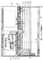
またこのときこれと併せて、図4に示すような新規のVFL作成画面42がディスプレイ32に表示される。このVFL作成画面42は、クリップの映像を目視確認しながら所望部分をカットとして切り出す操作を行うためのソースビューワ部60と、このようにして切り出された各カットをどのように並べるか、またその際カットの繋ぎ目においてどのような特殊効果を施すかといった編集内容を設定するためのタイムライン部61と、タイムライン部61において設定された編集内容を実際の映像により確認するためのマスタービューワ部62とから構成されるものである。
【0044】
そしてオペレータは、サーバサイトエクスプローラウインド41のクリップ表示部51に表示された各クリップのアイコン53の中から所望のクリップのアイコン53をドラッグアンドドロップによりVFL作成画面42のソースビューワ部60内に移動させることで、そのクリップを編集に利用するクリップとして選択することができ、この操作を繰り返すことにより複数のクリップをまとめて編集に利用するクリップとして選択することができる。
【0045】
またオペレータは、VFL作成画面42におけるソースビューワ部60の上側に表示されたクリップ選択メニュー表示ボタン70をクリックすることにより、上述のようにして選択したクリップの一覧をメニュー表示させることができ、さらにこのメニューの中から所望するクリップをクリックすることにより編集処理対象として選択することができる。なおこのとき選択されたクリップの名前がクリップリストボックス71内に表示されると共に、この当該クリップの例えば先頭フレームの映像がソースビューワ部60に表示される。
【0046】
そしてVFL作成画面42では、このようにしてソースビューワ部60に映像表示されたクリップのプロキシサーバ6(図1)に収録されている低解像度映像音声データD2に基づく映像を、ソースビューワ部60の下側に表示された複数の各種コマンドボタン72の中から対応するコマンドボタン72をクリックすることによって、通常再生、コマ送り再生又はコマ戻し再生等させることができる。
【0047】
実際上、CPU20は、かかる複数のコマンドボタン72の中から通常再生用、コマ送り再生用又はコマ送り逆再生用等のコマンドボタン72がクリックされると、これに応じてシステム制御部5を介してプロキシサーバ6を制御することにより、当該クリップにおける対応する映像音声部分の低解像度映像音声データD2を出力させる。この結果この低解像度映像音声データD2に基づく低解像度の通常再生映像や、コマ送り再生映像又はコマ送り逆再生映像等がソースビューワ部60に表示されることとなる。
【0048】
かくしてオペレータは、このソースビューワ部60に表示されたクリップの再生映像を目視確認しながらコマンドボタン72のうちのマークインボタン72IN又はマークアウトボタン72OUTをクリックするようにして、このクリップの映像音声の中からカットとして利用しようとする映像音声部分の開始点(イン点)や終了点(アウト点)を指定することができる。
【0049】
またこのようにイン点やアウト点を指定した場合、ソースビューワ部60における表示映像の下側に表示されたポジションバー73のイン点又はアウト点と対応する位置(すなわち、ポジションバー73の長さをそのクリップの素材長とした場合におけるイン点又はアウト点と対応する位置)に、それぞれイン点位置を表すマーク(以下、これをイン点マークと呼ぶ)74INやアウト点位置を表すマーク(以下、これをアウト点マークと呼ぶ)74OUTが表示される。
【0050】
一方、オペレータは、このようにして指定した各クリップのカットとして利用しようとする映像音声部分を用いて、以下の手順によりVFLを作成することができる。
【0051】
すなわち、まず上述のようにクリップのうちのカットとして利用しようとする映像音声部分の範囲を決定後、タイムライン部61内に表示されたプレイライン75を、当該タイムライン部61の下部に表示されたタイムスケール76を指標としてマウス操作により所望位置に移動させ、この後ソースビューワ部60の下部に表示された各種コマンドボタン72のうちのオーバーライトボタン72O又はスプライスインボタン72Sをクリックするようにする。
【0052】
この結果、図5に示すように、オーバーライトボタン72Oがクリックされたときには上書き、スプライスインボタン72Sがクリックされたときには挿入するようにして、タイムライン部61のビデオトラック77V上に、そのときのプレイライン75の位置を先頭位置とする当該映像音声部分の素材長に応じた長さの着色領域78Vが表示される。
【0053】
またこのときその映像音声部分に音声が付随している場合には、ビデオトラック77Vの下側に設けられた複数のオーディオトラック77A1〜77A4のうちの該当するチャンネル数分のオーディオトラック77A1〜77A4上に、それぞれそのときのプレイライン75の位置を先頭位置とするビデオトラック77Vの対応する着色領域78Vと同じ長さの着色領域78A1〜78A4が表示される。
【0054】
因みに、このときCPU20は、かかるオペレータの操作に応じたコマンドをシステム制御部5に通知する。この結果、システム制御部5の制御のもとに、素材サーバ3(図1)から対応するクリップにおける当該映像音声部分の高解像度映像音声データD1がイン点側及びアウト点側にそれぞれ数秒程度の余裕をもたせて読み出され、これがゲートウェイ13(図1)、FCスイッチャ14(図1)を介してその編集端末装置91〜9n用のデータI/Oキャッシュ部151〜15nに与えられて記憶される。
【0055】
さらに編集映像音声の再生時に映像音声部分の映像に付随する音声以外の音声を出力させたいときには、クリップ選択メニュー表示ボタン70をクリックし、このとき表示されたクリップの一覧の中から予め登録しておいたその音声のクリップを選択した後、タイムライン部61のプレイライン75を所望する位置に移動させ、この後所望するオーディオトラック77A1〜77A4を指定した上で上述のオーバーライトボタン72O又はスプライスインボタン72Sをクリックするようにする。
【0056】
そしてこの場合にも、その指定されたオーディオトラック77A1〜77A4上にそのときのプレイライン75の位置を先頭位置とする当該クリップの素材長に対応する長さの着色領域78A1〜78A4が表示されると共に、このクリップが素材サーバ3に収録されている場合には、その音声データが素材サーバ3から読み出されてデータI/Oキャッシュ部151〜15nに記憶されることとなる。
【0057】
そしてオペレータは、所望する各クリップについて、上述のような映像音声部分の選択(カットの切り出し)と、当該映像音声部分のタイムライン部61への貼り付け(ビデオトラック77V及び対応するオーディオトラック78A1〜78A4に着色領域78V、78A1〜78A4を表示させること)という操作を繰り返し行い、図6に示すように、タイムスケール76の始め(「00:00.00:00」)から所望する時間分だけ当該タイムスケール76上において連続するように、ビデオトラック77Vと、オーディオトラック77A1〜77A4上にそれぞれ着色領域78V、78A1〜78A4を順次表示させるようにする。
【0058】
ここでこのようにタイムライン部61のビデオトラック77V上やオーディオトラック77A1〜77A4上に着色領域78V、78A1〜78A4が表示されることは、編集映像音声の再生時にタイムスケール76で表された時間にその着色領域78V、78A1〜78A4と対応するカット内の対応する箇所の映像が表示され、又は音声が出力されることを意味する。従って、このような作業により編集映像音声として表示又は出力される映像音声の順番及び内容を規定したVFLを作成することができる。
【0059】
因みに、タイムライン部61に表示させるビデオトラック77Vやオーディオトラック77A1〜77A4の本数は自由に設定することができる。そして複数本のビデオトラック77Vやオーディオトラック77A1〜77A4が表示された状態において、これらビデオトラック77V又はオーディオトラック77A1〜77A4にそれぞれカットやクリップが貼り付けられている場合には、各ビデオトラック77Vにおけるタイムスケール76上で同じ位置の各映像を重ね合わせた映像が編集映像として得られ、各オーディオトラック77A1〜77A4におけるタイムスケール76上で同じ位置の各音声を重ね合わせた音声が編集音声として得られることとなる。
【0060】
さらにこのようにしてVFLを作成する際、例えば連続する第1のカットの映像から第2のカットの映像への切り換わり時に特殊効果処理を施したいときには、以下の手順により所望する映像特殊効果処理の設定を行うことができる。
【0061】
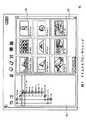
すなわち、まず先行する第1のカットと、第2のカットとをポジションバー96上で連続するようにビデオトラック77Vに貼り付け、この後タイムライン部61の上部に表示された各種ボタン80の中からFXエクスプローラボタン80FXをクリックする。これにより、例えば図7に示すように、この編集端末装置91〜9nが実行できる各種映像特殊効果がツリー形式でツリー表示部82に表示され、これら映像特殊効果の内容がアイコン形式でアイコン表示部83に表示されたウインド(以下、これをFXエクスプローラウインドと呼ぶ)81を表示させることができる。
【0062】
続いて、このFXエクスプローラウインド81のアイコン表示部83内に表示されたアイコン(以下、これを特殊効果アイコンと呼ぶ)84の中から所望する映像特殊効果処理の特殊効果アイコン84をドラッグアンドドロップにより、VFL作成画面42のビデオトラック77Vにおける上述の第1及び第2のカットの切り替わり箇所に貼り付ける。
【0063】
これにより編集映像の生成時において、第1のカットの映像から第2のカットの映像に切り替わる際に上述のようにして貼り付けられた特殊効果アイコンに対応する映像特殊効果処理が実行されることとなる。
【0064】
またVFLを作成する際、いずれかのオーディオトラック77A1〜77A4に貼り付けられたカットやクリップの音声に対して音声ミキシング処理を施したい場合には、以下の手順により所望の音声ミキシング処理を設定することができる。
【0065】
すなわち、まずVFL作成画面42のタイムライン部61に表示されたプレイライン75を、オーディオトラック77A1〜77A4に貼り付けられたカットやクリップのうちの音声ミキシング処理したいカット又はクリップと対応する着色領域78A1〜78A4上に移動させた後、当該タイムライン部61の上部に表示された複数のボタンの中からオーディオミキサーボタン80MIXをクリックする。
【0066】
この結果、図8に示すようなVFL作成画面42のタイムライン部61の各オーディオトラック77A1〜77A4にそれぞれ対応させてボリューム91やレベルメータ92及び各種設定ボタン93A〜93F等が設けられたオーディオミキサーウインド90が表示される。
【0067】
そしてこの後、このオーディオミキサーウインド90内に表示された、VFL作成画面42のタイムライン部61の所望するオーディオトラック77A1〜77A4と対応付けられたボリューム91や設定ボタン93A〜93F等をレベルメータ92を目視確認しながら操作する。
【0068】
これにより編集音声の出力時において、そのオーディオトラック77A1〜77A4に貼り付けられたカット又はクリップの再生時に上述のようにして設定された内容で当該カット又はクリップの音声データが音声ミキシング処理されることとなる。
【0069】
さらにVFL作成画面42では、上述のようにしてVFLを作成し終えた後又はVFLの作成中に、タイムライン部61内のプレイライン75をマウス操作により所望位置に移動させ、この後マスタービューワ部62の下側に表示された複数のコマンドボタン90の中からプレビューボタン90PVをクリックすることにより、そのときのプレイライン75の位置と対応する映像音声部分を開始点として、高解像度の編集映像をマスタービューワ部62内に通常再生表示させることができる。
【0070】
実際上、CPU20は、かかるプレビューボタン90PVがクリックされると、映像特殊効果及び音声ミキシング処理部25(図2)を制御することにより、このときデータI/Oキャッシュ部151〜15nが記憶保持している対応する映像音声部分の高解像度映像音声データD1を読み出させ、当該高解像度映像音声データD1に対して必要に応じて映像特殊効果処理や音声ミキシング処理を施させる。
【0071】
この結果、かかる映像特殊効果処理や音声ミキシング処理によって得られた高解像度の編集映像音声データが生成され、これがデータ処理部24に与えられることにより、当該編集映像音声データに基づく編集映像がVFL作成画面42のマスタービューワ部62内に再生表示されると共に、編集音声がスピーカ33から出力される。
【0072】
これによりオペレータは、このVFL作成画面42のマスタービューワ部62内に表示された編集映像に基づいて随時編集内容を目視確認(プレビュー)しながらVFLを作成し、又は作成し終えたVFLの内容を確認することができる。
【0073】
そしてこのようにしてVFLを作成後、クリップエクスプローラウインド40(図3)のクリップ表示部51内に表示されたこのVFLのシーケンスクリップのクリップアイコン54をドラッグアンドドロップによりサーバサイトエクスプローラウインド41(図3)のクリップ表示部51内に移動させることにより、このVFLに基づく編集結果を素材サーバ3(図1)に登録することができる。
【0074】
このときオペレータは、このVFLに基づく編集結果を素材サーバ3に登録する際の登録モードとして、図9(A)に示すように、当該VFLに基づく編集映像音声の全範囲の編集映像音声データD3を素材サーバ3に登録する全体登録モードと、図9(B)に示すように、編集映像音声のうちの映像特殊効果処理又は音声ミキシング処理が施された各映像音声部分(すなわち編集映像音声のうちの素材サーバ3に収録されていない映像音声部分)の編集映像音声データD3のみを一括登録する一括部分登録モードとのいずれか一方を選択して設定することができる。そして、そのためのダイアログ(以下、これを登録モード設定ダイアログと呼ぶ)が、かかるVFLのシーケンスクリップのクリップアイコン54をサーバサイトエクスプローラウインド41のクリップ表示部51内にドラッグアンドドロップしたときに表示される。
【0075】
このとき登録モードとして全体登録モードを選択すると、そのとき作成されたVFLにより規定された編集映像音声の全範囲についての編集映像音声データD3が生成され、これが素材サーバ3に与えられて上述のシーケンスクリップのファイル内に格納される。またこれと併せてこのVFLのデータ(以下、これを単にVFLデータと呼ぶ)がイーサネット(登録商標)7を介してプロジェクトファイル管理装置10(図1)に与えられ、この後このプロジェクトファイル管理装置10によりこのVFLデータが記憶管理される。
【0076】
これに対して登録モードとして一括部分登録モードを選択すると、そのとき作成されたVFLに基づく編集映像音声のうち、映像特殊効果処理又は音声ミキシング処理を施すべき各映像音声部分(すなわち実際に映像特殊効果処理又は音声ミキシング処理が開始されてから終了するまでの映像音声部分)についてのみ編集映像音声データD3がそれぞれ生成され、これらが素材サーバ3に与えられて上述のシーケンスクリップのファイル内に格納される。またこれと併せてこのVFLデータがイーサネット(登録商標)を介してプロジェクトファイル管理装置10に与えられ、この後このプロジェクトファイル管理装置10によりこのVFLデータが記憶管理される。
【0077】
なお、このように編集結果が部分的に登録された場合、その編集結果の再生時には、図10に示すように、元々素材サーバ3に収録されていたクリップのうちの編集映像音声として採用された部分(図10の斜線A及びCの部分)と、シーケンスクリップとして素材サーバ3に登録された映像特殊効果処理又は音声ミキシング処理が施された部分(図10の斜線B及びDの部分)とがVFLに従って順番に素材サーバ3から読み出されることとなる。
【0078】
一方、この編集端末装置91〜9nには、作成されたVFLに基づく編集結果を部分的に素材サーバ3に登録する部分登録モードとして、上述のように映像特殊効果処理又は音声ミキシング処理を施すべき各映像音声部分の編集映像音声データD3のみをVFLの作成後に一括して素材サーバ3に登録する一括部分登録モードの他に、VFLの作成段階において映像特殊効果処理又は音声ミキシング処理を施すべき各映像音声部分の編集映像音声データD3のみを素材サーバ3に逐次登録する逐次部分登録モードが設けられている。
【0079】
そして編集端末装置91〜9nでは、初期設定としてこの逐次部分登録モードが設定されている場合、VFLの作成途中において、VFL作成画面42(図4)におけるマスタービュー欄62(図4)内のプレビューボタン90PV(図4)がクリックされることにより、映像特殊効果処理又は音声ミキシング処理を施すべき旨の設定が行われた映像音声部分についての通常再生表示を行うごとに、このとき映像特殊効果処理や音声ミキシング処理により得られた当該映像音声部分の編集映像音声データD3を素材サーバ3に逐次転送するようになされている。そしてこの部分的な編集映像音声データD3が、そのVFLに対応させて素材サーバ3内に生成されたシーケンスクリップのファイル内に格納される。
【0080】
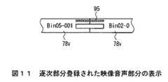
またこのように部分的な編集映像音声データD3の素材サーバ3への登録が行われた場合、VFL作成画面42のタイムライン部61における対応する映像特殊効果処理を施すべき旨の設定を行った映像音声部分や、音声ミキシング処理を施すべき旨の設定を行った映像音声部分の上側に図11に示すような赤色のライン95が表示される。
【0081】
さらにこの後そのVFLの作成が終了して、当該VFLのシーケンスクリップのクリップアイコン54(図3)をドラッグアンドドロップによりサーバサイトエクスプローラウインド41(図3)のクリップ表示部51(図3)内にすると、このVFLに基づく編集映像音声のうちの映像特殊効果処理又は音声ミキシング処理を施すべき各映像音声部分のうち、未だ映像特殊効果処理又は音声ミキシング処理により得られた当該映像音声部分の編集映像音声データD3が素材サーバ3に登録されていない各映像音声部分について、これら映像音声部分の編集映像音声データD3が生成され、これが素材サーバ3に一括して転送される。そしてこの部分的な編集映像音声データD3が、上述のようにそのVFLに対応させて素材サーバ3内に設けられたシーケンスクリップのファイル内に格納される。
【0082】
またこのときこれと併せてこのVFLデータがイーサネット(登録商標)7(図1)を介してプロジェクトファイル管理装置10(図1)に与えられ、この後このプロジェクトファイル管理装置10により記憶及び管理される。
【0083】
このようにしてこの編集端末装置91〜9nにおいては、作成されたVFLに基づく全範囲の編集映像音声データD3を素材サーバ3に登録する場合に比して格段的に高速に編集結果を素材サーバ3に登録し得るようになされている。
【0084】
(4)編集結果登録処理手順
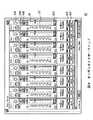
ここで上述のような作成されたVFLに基づく編集結果の素材サーバ3への登録は、図12に示す第1の編集結果登録処理手順RT1又は図13に示す第2の編集結果登録処理手順RT2に従った編集端末装置91〜9n内のCPU20(図2)の制御のもとに行われる。
【0085】
実際上、CPU20は、逐次部分登録モードが設定されていない状態において、オペレータ操作によりVFLのシーケンスクリップのクリップアイコン54(図3)がドラッグアンドドロップによりサーバサイトエクスプローラウインド41(図3)のクリップ表示部51(図3)内に移動されると、図12に示す第1の編集結果登録処理手順RT1をステップSP0において開始し、続くステップSP1において上述の登録モード設定ダイアログを表示させる。
【0086】
続いてCPU20は、ステップSP2に進んで、登録モード設定ダイアログが操作されて登録モードとして全体登録モード及び部分登録モードのいずれか一方が選択されるのを待ち受ける。
【0087】
そしてCPU20は、やがてオペレータにより登録モードとして全体登録モード及び部分登録モードのいずれか一方が選択されると、ステップSP3に進んで、選択された登録モードが全体登録モードであるか否かを判断する。
【0088】
CPU20は、このステップSP3において肯定結果を得ると、ステップSP4に進んで、このとき作成されたVFLに従って映像特殊効果及び音声ミキシング部24(図2)を制御することにより、VFLにより規定された編集内容の全範囲について、編集映像音声の生成に必要な高解像度映像音声データD1を対応するデータI/Oキャッシュ部151〜15nから順次読み出させ、当該高解像度映像音声データD1に対してVFLに従って必要に応じて特殊効果処理や音声ミキシング処理を実行させる。
【0089】
この結果、VFLに従った全範囲の編集映像音声データD3が映像特殊効果及び音声ミキシング部24において生成され、これが素材サーバ3内に移動された当該VFLと対応付けられたシーケンスクリップのファイル内に格納される。
【0090】
またCPU20は、これと併せてこのVFLのデータ(以下、これを単にVFLデータと呼ぶ)をイーサネット(登録商標)7を介してプロジェクトファイル管理装置10に送信し、この後ステップSP6に進んでこの第1の編集映像音声処理手順RT1を終了する。
【0091】
これに対してCPU20は、ステップSP3において否定結果を得ると、ステップSP5に進んで、このとき作成されたVFLの内容をサーチすることにより、編集内容の中から映像特殊効果処理又は音声ミキシング処理を施すべき旨の設定がなされた映像音声部分を検索し、当該検索結果と当該VFLとに基づいて映像特殊効果及び音声ミキシング部24を制御する。
【0092】
この結果、このVFLに基づく編集映像音声のうち、映像特殊効果処理又は音声ミキシング処理を施すべき各映像音声部分に関する高解像度映像音声データD1のみがデータI/Oキャッシュ部151〜15nから読み出され、この高解像度映像音声データD1が映像特殊効果及び音声ミキシング部24において当該VFLに基づいて映像特殊効果処理又は音声ミキシング処理され、かくして得られた部分的な編集映像音声データD3が素材サーバ3に移動された当該VFLと対応付けられたシーケンスクリップのファイル内に格納される。
【0093】
またCPU20は、これと併せてこのVFLデータをイーサネット(登録商標)7を介してプロジェクトファイル管理装置10に送信し、この後ステップS6Pに進んでこの第1の編集映像音声処理手順RT1を終了する。
【0094】
一方CPU20は、逐次部分登録モードが初期設定されている場合には、クリップエクスプローラウインド40(図3)の新規シーケンス作成ボタン53(図3)がクリックされると、ディスプレイ32(図2)に新規のVFL作成画面42(図4)を表示させるのと同時に図13に示す第2の編集映像音声処理手順RT2をステップSP10において開始し、続くステップSP11において、VFL作成画面42におけるマスタービュー欄62(図4)のプレビューコマンドボタン90PV(図4)がクリックされたか否かを判断する。
【0095】
そしてCPU20は、このステップSP11において否定結果を得るとステップSP13に進んで、クリップエクスプローラウインド40(図3)のクリップ表示部51(図3)に表示されたこのVFLと対応付けられたシーケンスクリップのクリップアイコン54(図3)がドラッグアンドドロップによりサーバサイトエクスプローラウインド41(図3)のクリップ表示部51内に移動された否かを判断する。
【0096】
またCPU20は、このステップSP13において否定結果を得ると、ステップSP11に戻り、この後ステップSP11又はステップSP13において肯定結果を得るまでステップSP11−SP13−SP11のループを繰り返す。
【0097】
そしてCPU20は、やがてオペレータがマウス操作によりVFL作成画面42におけるマスタービュー欄62のプレビューコマンドボタン90PVをクリックすることによりステップSP11において肯定結果を得ると、ステップSP11からステップSP12に進んで、そのとき作成中のVFLの内容に従って映像特殊効果及び音声ミキシング部24を制御する。
【0098】
この結果、映像特殊効果及び音声ミキシング部24により必要な高解像度映像音声データD1がデータI/Oキャッシュ部151〜15nから読み出され、この高解像度映像音声データD1が映像特殊効果及び音声ミキシング部24において必要に応じて映像特殊効果処理又は音声ミキシング処理される。そしてこのとき得られた編集映像音声データD3に基づく高解像度の映像がVFL作成画面42のマスタービュー欄62(図4)に表示される。
【0099】
またこのときCPU20は、これと併せてそのとき再生している編集映像音声が映像特殊効果処理又は音声ミキシング処理を施すべき映像音声部分であるか否かを順次判断し、肯定結果を得た場合には映像特殊効果及び音声ミキシング部24を制御して、そのとき映像特殊効果及び音声ミキシング部24により生成された編集映像音声データD3を素材サーバ3に送出させる。かくしてこの映像特殊効果処理又は音声ミキシング処理を施すべき映像音声部分の編集映像音声データD3が、そのVFLに対応させて素材サーバ3内に設けられたシーケンスクリップのファイル内に格納される。
【0100】
そしてCPU20は、やがてオペレータによるマウス操作によりプレビューの停止命令が入力されると、ステップSP13に進み、この後上述と同様にしてステップSP11〜SP13を繰り返すことにより、作成中のVFLにおいて規定されている映像特殊効果処理又は音声ミキシング処理を施すべき各映像音声部分のうちのプレビューした映像音声部分の編集映像音声データD3を素材サーバ3内に設けられたシーケンスクリップのファイル内に格納される。
【0101】
一方、CPU20は、やがてステップSP13において肯定結果を得ると、ステップSP14に進んで、このとき作成されたVFLに基づく編集映像音声のうちの映像特殊効果処理又は音声ミキシング処理を施すべき各映像音声部分のうち、その編集映像音声データD3が未だ素材サーバ3に登録されていないものがあるか否かを判断する。
【0102】
そしてCPU20は、このステップSP14において肯定結果を得るとステップSP15に進んで映像特殊効果及び音声ミキシング処理部25を制御することにより、その編集映像音声データD3が未だ素材サーバ3に登録されていない映像特殊効果処理又は音声ミキシング処理を施すべき各映像音声部分について、それぞれその高解像度映像音声データD1をデータI/Oキャッシュ部151〜15nから順次読み出させて、この高解像度映像音声データD1に対して対応する映像特殊効果処理又は音声ミキシング処理を実行させ、かくして得られた編集映像音声データD3を素材サーバ3に順次送出させる。この結果この編集映像音声データD3が、そのVFLに対応させて素材サーバ3内に設けられたシーケンスクリップのファイル内に格納される。
【0103】
またCPU20は、これと併せてこのVFLデータをイーサネット(登録商標)7を介してプロジェクトファイル管理装置10に送信し、この後ステップSP16に進んでこの第2の編集結果登録処理手順RT2を終了する。
【0104】
このようにしてCPU20は、作成されたVFLに基づく編集結果を、オペレータにより設定された登録モードで素材サーバ3に登録する。
【0105】
(5)本実施の形態の動作及び効果
以上の構成において、このオンエアーシステム1の編集端末装置91〜9nは、一括部分登録モード時又は逐次部分登録モード時、作成されたVFLに基づく編集により得られるべき編集映像音声データD3のうち、映像特殊効果処理又は音声ミキシング処理を実行すべき映像音声部分の編集映像音声データD3のみを編集結果として素材サーバ3に登録する。
【0106】
そしてこの編集結果の再生時には、もともと素材サーバ3に収録されているクリップのうちの編集映像音声として採用された部分と、編集結果として素材サーバ3に登録された映像特殊効果処理又は音声ミキシング処理が施された部分とをVFLに従って順番に素材サーバ3から読み出すことにより、当該VFLに基づく全範囲の編集映像音声を得る。
【0107】
従って、このオンエアーシステム1では、VFLに基づき得られる編集映像音声の全範囲の編集映像音声データD3を生成しながら素材サーバ3に登録する場合に比して、VFLに基づく編集結果の素材サーバ3への登録を高速化することができ、その分ユーザの待ち時間を短縮させることができる。
【0108】
以上の構成によれば、作成されたVFLに基づく編集により得られるべき編集映像音声データD3のうち、映像特殊効果処理又は音声ミキシング処理を実行すべき映像音声部分の編集映像音声データD3のみを編集結果として素材サーバ3に登録するようにしたことにより、VFLに基づく編集結果の素材サーバ3への登録を格段的に高速化することができ、かくして編集結果を迅速に得られるオンエアーシステムを実現できる。
【0109】
(6)他の実施の形態
なお上述の実施の形態においては、本発明をオンエアーシステム1の編集端末装置91〜9nに適用するようにした場合について述べたが、本発明はこれに限らず、オンエアーシステム以外のシステムの編集装置や、単独で存在する編集装置など、この他種々の編集装置に広く適用することができる。
【0110】
また上述の実施の形態においては、一括部分登録モード時や逐次部分登録モード時に素材サーバ3に登録する映像特殊効果処理又は音声ミキシング処理を施すべき各映像音声部分の範囲として、実際に映像特殊効果処理又は音声ミキシング処理が開始されてから終了するまでの範囲を適用するようにした場合について述べたが、本発明はこれに限らず、実際に映像特殊効果処理又は音声ミキシング処理が開始されてから終了するまでの映像音声部分の両側にそれぞれ幾らかの余裕をもたせた範囲とするようにしても良い。
【0111】
さらに上述の実施の形態においては、編集結果を編集端末装置91〜9nの外部機器である素材サーバ3に登録し、VFLを編集端末装置91〜9nの外部機器であるプロジェクトファイル管理端末装置10に登録するようにした場合について述べたが、本発明はこれに限らず、VFL及びこれに基づく編集結果をまとめて1つのシーケンスクリップとして素材サーバ3に登録するようにしても良い。
【0112】
さらに上述の実施の形態においては、被編集素材が映像音声データである場合について述べたが、本発明はこれに限らず、アナログ又はディジタルの映像情報やアナログ又はディジタルの映像情報である場合にも本発明を広く適用することができる。
【0113】
さらに上述の実施の形態においては、被編集素材に対して所定の加工処理を施す加工手段としての映像特殊効果及び音声ミキシング処理部25が高解像度映像音声データD1に対して映像特殊効果処理及び音声ミキシング処理を行い得る機能を有するようにした場合について述べたが、本発明はこれに限らず、被編集素材の種類に応じて映像特殊効果処理及び音声ミキシング処理以外の加工処理を行い得るように加工手段を構成するようにしても良い。
【0114】
さらに上述の実施の形態においては、被編集素材に対して所定の加工処理を施す加工手段としての機能と、編集結果を外部機器に登録する登録手段としての機能とを映像特殊効果及び音声ミキシング処理部25にもたせるようにした場合について述べたが、本発明はこれに限らず、登録手段としての機能を有する回路ブロックを映像特殊効果及び音声ミキシング処理部25とは別に設けるようにしても良い。
【0115】
さらに上述の実施の形態においては、加工手段及び登録手段としての映像特殊効果及び音声ミキシング処理部25を制御する制御手段としてのCPU20が、逐次部分登録モード時にVFLの作成終了後、クリップエクスプローラウインド40のクリップ表示部51内に表示されたこのVFLのシーケンスクリップのクリップアイコン54をドラッグアンドドロップによりサーバサイトエクスプローラウインド41のクリップ表示部51内に移動させたときに、未だ映像特殊効果処理又は音声ミキシング処理により得られた当該映像音声部分の編集映像音声データD3が素材サーバ3に登録されていない各映像音声部分について一括して素材サーバ3に登録するようにした場合について述べたが、このように残りの各映像音声部分を一括して素材サーバ3に登録するトリガとしては、この他専用のボタンを設け、これがクリックされたときにするなど、種々のトリガを広く適用することができる。
【0116】
【発明の効果】
上述のように本発明によれば、編集内容を規定したリストに従って編集処理を実行し、得られた編集結果を外部機器に登録する編集装置において、外部機器に登録するモードとして、編集映像音声データの全範囲を登録する全体登録モード又は当該編集映像音声データのうち部分編集すべき部分を登録する部分登録モードのいずれか一方を選択して登録する登録モード選択手段と、リストに従って被編集素材の必要部分に対して映像特殊効果処理又は音声ミキシング処理を施すことによって部分編集映像音声データを生成する部分編集手段と、部分登録モードが選択された場合、部分編集すべき部分のみを読み出し、映像特殊効果処理又は音声ミキシング処理を施した部分編集映像音声データのみを一括して外部機器に登録する一括部分登録モード又は部分編集映像音声データのみを逐次外部機器に登録する逐次部分登録モードのいずれかを選択して部分編集映像音声データ登録する部分登録制御手段とを設けるようにしたことによって、部分登録モードが選択された場合、編集対象リストに基づく編集映像音声データの全範囲を登録する場合に比べて、編集映像音声データのうち部分編集すべき部分のみを読み出して部分編集できるため、編集結果の外部機器への登録の高速化を図ることができ、かくして編集結果を迅速に登録し得る編集装置を実現できる。
【0117】
また本発明によれば、編集方法において、編集内容を規定したリストに従って編集処理を実行し、得られた編集結果を外部機器に登録する編集装置において、外部機器に登録するモードとして、編集映像音声データの全範囲を登録する全体登録モード又は当該編集映像音声データのうち部分編集すべき部分を登録する部分登録モードのいずれか一方を選択して登録する登録モード選択ステップと、リストに従って被編集素材の必要部分に対して映像特殊効果処理又は音声ミキシング処理を施すことによって部分編集映像音声データを生成する部分編集ステップと、部分登録モードが選択された場合、部分編集すべき部分のみを読み出し、映像特殊効果処理又は音声ミキシング処理を施した部分編集映像音声データのみを一括して外部機器に登録する一括部分登録モード又は部分編集映像音声データのみを逐次外部機器に登録する逐次部分登録モードのいずれかを選択して部分編集映像音声データ登録する部分登録制御ステップとを設けるようにことにより、部分登録モードが選択された場合、編集対象リストに基づく編集映像音声データの全範囲を登録する場合に比べて、編集映像音声データのうち部分編集すべき部分のみを読み出して部分編集できるため、編集結果の外部機器への登録の高速化を図ることができ、かくして編集結果を迅速に登録し得る編集方法を実現できる。
【図面の簡単な説明】
【図1】本実施の形態によるオンエアーシステムの全体構成を示すブロック図である。
【図2】編集端末装置の構成を示すブロック図である。
【図3】クリップエクスプローラウインドを示す略線図である。
【図4】VFL作成画面を示す略線図である。
【図5】VFL作成画面を示す略線図である。
【図6】VFL作成画面を示す略線図である。
【図7】FXエクスプローラウインドを示す略線図である。
【図8】オーディオ音声ミキシングインドを示す略線図である。
【図9】全体登録モード及び部分登録モードの説明に供する概念図である。
【図10】部分登録された編集結果の再生処理の説明に供する概念図である。
【図11】部分登録モードの説明に供する略線図である。
【図12】第1の編集結果登録処理手順を示すフローチャートである。
【図13】第2の編集結果登録処理手順を示すフローチャートである。
【符号の説明】
1……オンエアーシステム、3……素材サーバ、91〜9n……編集端末装置、151〜15n……データI/Oキャッシュ部、20……CPU、25……映像特殊効果及び音声ミキシング処理部、32……ディスプレイ、40……クリップエクスプローラウインド、41……サーバサイトエクスプローラウインド、42……VFL作成画面、54……クリップアイコン、61……タイムライン部、62……マスタービューワ部、90PV……プレビューコマンドボタン、95……ライン、D1……高解像度映像音声データ、D2……低解像度映像音声データ、D3……編集映像音声データ。[0001]
BACKGROUND OF THE INVENTION
The present invention relates to an editing apparatus and method, and is suitable for application to, for example, an on-air system used in a television broadcasting station.
[0002]
[Prior art]
Conventionally, in an on-air system, video and audio obtained by interviews are processed and edited to a desired state using an editing device, and the resulting edited video and audio (hereinafter referred to as edited video and audio) is broadcast. Clip (video / audio material) can be registered in the server, and the clip registered in the server can be read and broadcast at a predetermined timing (for example, see Patent Document 1).
[0003]
[Patent Document 1]
JP-A-10-285533
[0004]
[Problems to be solved by the invention]
By the way, for example, at the site of news program creation, it is required to quickly edit and broadcast the video and audio obtained by the interview, and more promptness is required particularly when broadcasting special news.
[0005]
However, the editing device used in the conventional on-air system functionally requires a lot of time for the editing processing for video and audio, and especially the special effect processing applied to the video processing at a speed higher than real time. There was a problem that could not be done.
[0006]
Therefore, for example, in an editing device used in an on-air system, if the editing result can be obtained more quickly than it is now, the waiting time of the editing result can be shortened and emergency news such as broadcasting temporary news can be obtained. Is considered to be able to respond more fully than now.
[0007]
The present invention has been made in consideration of the above points, and an object of the present invention is to propose an editing apparatus and method capable of quickly obtaining an editing result.
[0008]
[Means for Solving the Problems]
In order to solve such a problem, in the present invention, in an editing apparatus that executes editing processing according to a list that defines editing contents and registers the obtained editing result in the external device, the mode is registered in the external device.Register the entire range of edited video and audio dataWhole registration mode orRegister the part of the edited video / audio data to be partially editedPartial registration modeEither one ofTheSelect to registerRegistration modeChoiceMeans, partial editing means for generating partial edited video / audio data by performing video special effect processing or audio mixing processing on a necessary portion of the material to be edited according to the list, and a partial registration modeChoiceIfParts to be partially editedOnlyBatch partial registration mode in which only partial edited video / audio data subjected to readout, video special effect processing or audio mixing processing are registered in the external device in batch or sequential partial registration mode in which only partial edited video / audio data is registered in the external device Select any of the and register the partially edited video / audio data.And a partial registration control means.
[0009]
As a result, based on the listEdited video / audio dataCompared to registering the entire range,The edited video / audio data should be partially editedPartially edited video / audio dataonlyTheReading and partial editingTherefore, the editing result can be registered in the external device at high speed.
[0010]
In the present invention, in the editing method, the editing process is performed according to the list that defines the editing content, and the editing result is registered in the external device.Register the entire range of edited video and audio dataWhole registration mode orRegister the part of the edited video / audio data to be partially editedPartial registration modeEither one ofTheSelect to registerRegistration modeChoiceA partial editing step for generating partial edited video / audio data by performing video special effect processing or audio mixing processing on a necessary portion of the material to be edited according to the list, and a partial registration modeChoiceIfParts to be partially editedOnlyBatch partial registration mode in which only partial edited video / audio data subjected to readout, video special effect processing or audio mixing processing are registered in the external device in batch or sequential partial registration mode in which only partial edited video / audio data is registered in the external device Select any of the and register the partially edited video / audio data.And a partial registration control step.
[0011]
As a result, according to this editing method, based on the listEdited video / audio dataCompared to registering the entire range,The edited video / audio data should be partially editedPartially edited video / audio dataonlyTheReading and partial editingTherefore, the editing result can be registered in the external device at high speed.
[0012]
DETAILED DESCRIPTION OF THE INVENTION
Hereinafter, an embodiment of the present invention will be described in detail with reference to the drawings.
[0013]
(1) Configuration of on-air system according to this embodiment
In FIG. 1,
[0014]
The
[0015]
The down-
[0016]
Similar to the
[0017]
In this manner, in the on-
[0018]
The low-resolution video / audio data D2 of each clip stored in the proxy server 6 is sent to each proxy
[0019]
In practice, the proxy
[0020]
The proxy
[0021]
Further, the VFL data thus created (hereinafter simply referred to as VFL data) is generated by the proxy
[0022]
On the other hand, the editing terminal device 91~ 9nIs a nonlinear editing device equipped with a video board that can perform real-time video special effect processing on the high-resolution video / audio data D1 recorded in the
[0023]
Editing terminal device 91~ 9nThe
[0024]
The editing terminal device 91~ 9nIn the VFL creation process, the VFL is accessed by accessing the
[0025]
As a result, the high-resolution video / audio data D1 read from the
[0026]
And the editing terminal device 91~ 9nWhen the VFL creation operation by the operator is finished and an execution instruction for this VFL is input thereafter, the data I /
[0027]
Further, the edited video / audio data D3 recorded in the
[0028]
In this way, the on-
[0029]
(2) Editing terminal device 91~ 9nConfiguration
Here, the editing terminal device 91~ 9nAs shown in FIG. 2, a CPU (Central Processing Unit) 20, a ROM (Read Only Memory) 21 storing various programs and parameters, a RAM (Random Access Memory) 22 as a work memory of the
[0030]
The interface unit 27 is connected to input devices such as a
[0031]
In the VFL creation mode, the
[0032]
In the VFL creation mode, the
[0033]
Further, for example, the
[0034]
Further, the
[0035]
(3) Editing terminal device 91~ 9nFor creating VFL in Japan
Next, this editing terminal device 91~ 9nThe VFL creation procedure will be described.
[0036]
Editing terminal device 91~ 9nIn the VFL creation mode, the
[0037]
In this case, the
[0038]
The
[0039]
The
[0040]
The server
[0041]
In the
[0042]
Then, when creating a new VFL, the operator clicks a new
[0043]
At the same time, a new
[0044]
Then, the operator moves a desired
[0045]
The operator can display a list of clips selected as described above by clicking the clip selection
[0046]
On the
[0047]
In practice, when the
[0048]
Thus, the operator visually confirms the playback video of the clip displayed on the
[0049]
In addition, when the In point and Out point are designated in this way, the position corresponding to the In point or Out point of the
[0050]
On the other hand, the operator can create a VFL by the following procedure using a video / audio part to be used as a cut of each clip designated in this way.
[0051]
That is, first, after determining the range of the audio / video portion to be used as a cut of the clip as described above, the playline 75 displayed in the
[0052]
As a result, as shown in FIG.OWhen clicked, overwrite, splice in
[0053]
At this time, if the video / audio portion is accompanied by audio, the video track 77VA plurality of audio tracks 77 provided belowA1~ 77A4Audio tracks 77 for the corresponding number of channelsA1~ 77A4Above, a video track 77 starting from the position of the
[0054]
Incidentally, at this time, the
[0055]
Further, when it is desired to output audio other than the audio accompanying the video / audio portion during playback of the edited video / audio, click the clip selection
[0056]
Also in this case, the designated audio track 77A1~ 77A4A colored region 78 having a length corresponding to the material length of the clip with the position of the
[0057]
The operator then selects (cuts out) the video / audio part as described above for each desired clip, and pastes the video / audio part onto the timeline unit 61 (video track 77).VAnd corresponding audio track 78A1~ 78A4Colored area 78V78A1~ 78A4As shown in FIG. 6, the video is continuously displayed on the
[0058]
Here, the video track 77 of the
[0059]
Incidentally, the video track 77 displayed on the timeline unit 61.VAnd audio track 77A1~ 77A4The number of can be set freely. And multiple video tracks 77VAnd audio track 77A1~ 77A4In the state where is displayed, these video tracks 77 are displayed.VOr audio track 77A1~ 77A4If a cut or clip is attached to each video track 77, each video track 77VA video obtained by superimposing videos at the same position on the
[0060]
Furthermore, when creating a VFL in this way, for example, when it is desired to perform special effect processing when switching from a continuous first cut video to a second cut video, the desired video special effect processing is performed according to the following procedure. Can be set.
[0061]
That is, first, the video track 77 is set so that the preceding first cut and the second cut are continued on the position bar 96.VAfter that, the
[0062]
Subsequently, a
[0063]
Thereby, when the edited video is generated, the video special effect processing corresponding to the special effect icon pasted as described above is executed when the video of the first cut is switched to the video of the second cut. It becomes.
[0064]
When creating a VFL, one of the audio tracks 77A1~ 77A4When it is desired to perform the audio mixing process on the sound of the cut or clip pasted on, desired audio mixing process can be set by the following procedure.
[0065]
That is, first, the
[0066]
As a result, each audio track 77 in the
[0067]
Thereafter, a desired audio track 77 in the
[0068]
Thus, when the edited sound is output, the audio track 77 is output.A1~ 77A4The audio data of the cut or clip is subjected to audio mixing processing with the contents set as described above when the cut or clip pasted on is reproduced.
[0069]
Further, on the
[0070]
In practice, the
[0071]
As a result, high-resolution edited video / audio data obtained by such video special effect processing and audio mixing processing is generated and provided to the
[0072]
As a result, the operator creates the VFL while visually confirming (previewing) the edited content based on the edited video displayed in the
[0073]
After creating the VFL in this way, the
[0074]
At this time, the operator, as a registration mode when registering the editing result based on the VFL in the
[0075]
At this time, when the entire registration mode is selected as the registration mode, edited video / audio data D3 for the entire range of the edited video / audio defined by the VFL created at that time is generated, and this is given to the
[0076]
On the other hand, when the batch partial registration mode is selected as the registration mode, each video / audio part to be subjected to the video special effect process or the audio mixing process (that is, the actual video special part) among the edited video / audio generated based on the VFL at that time. Edited video / audio data D3 is generated only for the video / audio part) from the start to the end of the effect processing or audio mixing processing, and these are provided to the
[0077]
When the editing result is partially registered in this way, when the editing result is reproduced, as shown in FIG. 10, it is adopted as the edited video / audio of the clip originally recorded in the
[0078]
On the other hand, this editing terminal device 91~ 9nThe edited video / audio data of each video / audio portion to be subjected to the video special effect processing or the audio mixing processing as described above as a partial registration mode in which the editing result based on the created VFL is partially registered in the
[0079]
And the editing terminal device 91~ 9nIf the sequential partial registration mode is set as an initial setting, a
[0080]
Further, when the partial edited video / audio data D3 is registered in the
[0081]
Thereafter, the creation of the VFL is finished, and the clip icon 54 (FIG. 3) of the sequence clip of the VFL is dragged and dropped into the clip display section 51 (FIG. 3) of the server site explorer window 41 (FIG. 3). Then, among the video / audio portions to be subjected to the video special effect processing or the audio mixing processing in the edited video / audio based on the VFL, the edited video of the video / audio portion still obtained by the video special effect processing or the audio mixing processing. For each video / audio portion in which the audio data D3 is not registered in the
[0082]
At this time, this VFL data is also given to the project file management apparatus 10 (FIG. 1) via the Ethernet (registered trademark) 7 (FIG. 1), and thereafter stored and managed by the project
[0083]
In this way, the editing terminal device 91~ 9nIn FIG. 2, the editing result can be registered in the
[0084]
(4) Editing result registration processing procedure
Here, the editing result based on the created VFL as described above is registered in the
[0085]
In practice, when the sequential partial registration mode is not set, the
[0086]
Subsequently, the
[0087]
When the operator eventually selects either the overall registration mode or the partial registration mode as the registration mode, the
[0088]
If the
[0089]
As a result, the entire range of the edited video / audio data D3 according to the VFL is generated in the video special effect and
[0090]
At the same time, the
[0091]
On the other hand, if the
[0092]
As a result, of the edited video / audio based on the VFL, only the high-resolution video / audio data D1 related to each video / audio portion to be subjected to the video special effect processing or the audio mixing processing is stored in the data I / O cache unit 15.1~ 15nThe high-resolution video / audio data D1 is subjected to video special effect processing or audio mixing processing based on the VFL in the video special effect /
[0093]
At the same time, the
[0094]
On the other hand, when the sequential partial registration mode is initially set, when the new sequence creation button 53 (FIG. 3) of the clip explorer window 40 (FIG. 3) is clicked, the
[0095]
If the
[0096]
If the
[0097]
Then, the
[0098]
As a result, the high-resolution video / audio data D1 required by the video special effect and
[0099]
At this time, when the
[0100]
Then, when a preview stop command is input by a mouse operation by the operator, the
[0101]
On the other hand, if the
[0102]
If the
[0103]
At the same time, the
[0104]
In this way, the
[0105]
(5) Operation and effect of the present embodiment
In the above configuration, the editing terminal device 9 of the on-
[0106]
When the edited result is reproduced, the part originally adopted as the edited video / audio of the clip recorded in the
[0107]
Therefore, in this on-
[0108]
According to the above configuration, only the edited video / audio data D3 of the video / audio portion to be subjected to the video special effect processing or the audio mixing processing among the edited video / audio data D3 to be obtained by editing based on the created VFL is edited. As a result, by registering with the
[0109]
(6) Other embodiments
In the above-described embodiment, the present invention is applied to the editing terminal device 9 of the on-air system 1.1~ 9nAlthough the present invention is not limited to this, the present invention is not limited to this, and is widely applied to various other editing devices such as editing devices of systems other than the on-air system and independent editing devices. Can do.
[0110]
Further, in the above-described embodiment, the video special effect is actually set as the range of each video / audio part to be subjected to the video special effect process or the audio mixing process registered in the
[0111]
Furthermore, in the above-described embodiment, the editing result is sent to the editing terminal device 9.1~ 9nRegistered in the
[0112]
Further, in the above-described embodiment, the case where the material to be edited is video / audio data has been described. The present invention can be widely applied.
[0113]
Furthermore, in the above-described embodiment, the video special effect and audio
[0114]
Furthermore, in the above-described embodiment, the video special effect and audio mixing processing includes a function as a processing unit that performs a predetermined processing on the material to be edited and a function as a registration unit that registers an editing result in an external device. Although the case where the
[0115]
Further, in the above-described embodiment, the
[0116]
【The invention's effect】
As described above, according to the present invention, in the editing apparatus that executes the editing process according to the list that defines the editing content and registers the obtained editing result in the external device, the mode is registered in the external device.Register the entire range of edited video and audio dataWhole registration mode orRegister the part of the edited video / audio data to be partially editedPartial registration modeEither one ofTheSelect to registerRegistration modeChoiceMeans, partial editing means for generating partial edited video / audio data by performing video special effect processing or audio mixing processing on a necessary portion of the material to be edited according to the list, and a partial registration modeChoiceIfParts to be partially editedOnlyBatch partial registration mode for registering only partial edited video / audio data that has undergone readout, video special effect processing or audio mixing processing to the external device in batch or sequential partial registration mode for registering only partial edited video / audio data to the external device Select any of the and register the partially edited video / audio data.By providing partial registration control means,Editing target when partial registration mode is selectedBased on listEdited video / audio dataCompared to registering the entire range,Only the part of the edited video / audio data that should be editedTheReading and partial editingEdit resultsTo external equipmentRegistration can be speeded up, thus editing results quicklyCan registerAn editing device can be realized.
[0117]
Further, according to the present invention, in the editing method, in the editing apparatus that executes editing processing according to the list that defines the editing content and registers the obtained editing result in the external device, the mode is registered in the external device.Register the entire range of edited video and audio dataWhole registration mode orRegister the part of the edited video / audio data to be partially editedPartial registration modeEither one ofTheSelect to registerRegistration modeChoiceA partial editing step for generating partial edited video / audio data by performing video special effect processing or audio mixing processing on a necessary portion of the material to be edited according to the list, and a partial registration modeChoiceIfParts to be partially editedOnlyBatch partial registration mode for registering only partial edited video / audio data that has undergone readout, video special effect processing or audio mixing processing to the external device in batch or sequential partial registration mode for registering only partial edited video / audio data to the external device Select any of the and register the partially edited video / audio data.By providing a partial registration control step,Editing target when partial registration mode is selectedBased on listEdited video / audio dataCompared to registering the entire range,Only the part of the edited video / audio data that should be editedTheReading and partial editingEdit resultsTo external equipmentRegistration can be speeded up, thus editing results quicklyCan registerAn editing method can be realized.
[Brief description of the drawings]
FIG. 1 is a block diagram showing an overall configuration of an on-air system according to an embodiment.
FIG. 2 is a block diagram showing a configuration of an editing terminal device.
FIG. 3 is a schematic diagram showing a clip explorer window.
FIG. 4 is a schematic diagram showing a VFL creation screen.
FIG. 5 is a schematic diagram showing a VFL creation screen.
FIG. 6 is a schematic diagram showing a VFL creation screen.
FIG. 7 is a schematic diagram showing an FX explorer window.
FIG. 8 is a schematic diagram showing audio voice mixing India;
FIG. 9 is a conceptual diagram for explaining an entire registration mode and a partial registration mode.
FIG. 10 is a conceptual diagram for explaining a reproduction process of a partially registered editing result.
FIG. 11 is a schematic diagram for explaining a partial registration mode;
FIG. 12 is a flowchart showing a first editing result registration processing procedure;
FIG. 13 is a flowchart showing a second editing result registration processing procedure;
[Explanation of symbols]
1 ... On-air system, 3 ... Material server, 91~ 9n... Editing terminal device, 151~ 15nData I / O cache unit, 20 CPU, 25 Video special effects and audio mixing processing unit, 32 Display, 40 Clip explorer window, 41 Server site explorer window, 42 VFL Creation screen, 54 …… Clip icon, 61 …… Timeline section, 62 …… Master viewer section, 90PV... Preview command button, 95 .. Line, D1... High-resolution video / audio data, D2... Low-resolution video / audio data, D3.
Claims (4)
Translated fromJapanese上記外部機器に登録するモードとして、編集映像音声データの全範囲を登録する全体登録モード又は当該編集映像音声データのうち部分編集すべき部分を登録する部分登録モードのいずれか一方を選択して登録する登録モード選択手段と、
上記リストに従って被編集素材の必要部分に対して映像特殊効果処理又は音声ミキシング処理を施すことによって部分編集映像音声データを生成する部分編集手段と、
上記部分登録モードが選択された場合、上記部分編集すべき部分のみを読み出し、上記映像特殊効果処理又は上記音声ミキシング処理を施した上記部分編集映像音声データのみを一括して上記外部機器に登録する一括部分登録モード又は上記部分編集映像音声データのみを逐次上記外部機器に登録する逐次部分登録モードのいずれかを選択して上記部分編集映像音声データを登録する部分登録制御手段と
を具える編集装置。In the editing device that executes the editing process according to the list that defines the editing content and registers the obtained editing result in the external device,
As a mode toregister to the externaldevice,selectseither the partial registration modefor registering the part to be edited portions of the complete registration mode orthe edited video and audio datato register the full range of editing video and audio data and the registration modeselection means forregistering,
Partial editing means for generating partially edited video / audio data by performing video special effect processing or audio mixing processing on a necessary portion of the material to be edited according to the list;
When the partial registration mode isselected, only thepart to be partially edited isread out, and only thepartial edited video / audio data subjected to the video special effect process or the audio mixing process is registered in the external device at a time. batch part registration mode or the partial editing video and audio data only sequential the external device to select one of the sequential part registration mode to registerRu comprising a portion registration controlmeans for registering the partial editing video and audio dataediting apparatus.
請求項1に記載の編集装置。When the partially edited video / audio data issequentially registered in the external device in accordance with the sequential partial registration mode, the timeline display unit indicates the range of the video / audio part subjected to the video special effect processing or the audio mixing processing. indicate
Editing apparatus according to請 Motomeko 1.
上記外部機器に登録するモードとして、編集映像音声データの全範囲を登録する全体登録モード又は当該編集映像音声データのうち部分編集すべき部分を登録する部分登録モードのいずれか一方を選択して登録する登録モード選択ステップと、
上記リストに従って被編集素材の必要部分に対して映像特殊効果処理又は音声ミキシング処理を施すことによって上記部分編集映像音声データを生成する部分編集ステップと、
上記部分登録モードが選択された場合、上記部分編集すべき部分のみを読み出し、上記映像特殊効果処理又は上記音声ミキシング処理を施した上記部分編集映像音声データのみを一括して上記外部機器に登録する一括部分登録モード又は上記部分編集映像音声データのみを逐次上記外部機器に登録する逐次部分登録モードのいずれかを選択して上記部分編集映像音声データを登録する部分登録制御ステップと
を具える編集方法。In an editing method in which editing processing is executed according to a list that defines editing contents, and the obtained editing results are registered in an external device.
As a mode toregister to the externalequipment,selectseither the partial registration modefor registering the part to be edited portions of the complete registration mode orthe edited video and audio datato register the full range of editing video and audio data and the registration modeselection step ofregistering,
And portions editing step of generatingthe partial edit video and audio data by applying video special effects or audio mixing for the required portion of the edit material in accordance with the above list,
When the partial registration mode isselected, only thepart to be partially edited isread, and only thepartial edited video / audio data subjected to the video special effect process or the audio mixing process is registered in the external device in a batch. bulk partial registration mode or the partial edit video and audio data only sequential said external device to select one of the sequential part registration mode to registerRu comprising a partial registration control stepof registering the partial edit video and audio dataedited Method.
請求項3に記載の編集方法。When the partially edited video / audio data issequentially registered in the external device in accordance with the sequential partial registration mode, the timeline display unit indicates the range of the video / audio part subjected to the video special effect processing or the audio mixing processing. indicate
Editing method according to請 Motomeko3.
Priority Applications (5)
| Application Number | Priority Date | Filing Date | Title |
|---|---|---|---|
| JP2003170124AJP4168334B2 (en) | 2003-06-13 | 2003-06-13 | Editing apparatus and editing method |
| CNA2004800162316ACN1806289A (en) | 2003-06-13 | 2004-06-10 | Edition device and method |
| PCT/JP2004/008490WO2004112031A1 (en) | 2003-06-13 | 2004-06-10 | Edition device and method |
| KR1020057022725AKR20060018861A (en) | 2003-06-13 | 2004-06-10 | Editing apparatus and method |
| US10/560,358US20060168521A1 (en) | 2003-06-13 | 2004-06-10 | Edition device and method |
Applications Claiming Priority (1)
| Application Number | Priority Date | Filing Date | Title |
|---|---|---|---|
| JP2003170124AJP4168334B2 (en) | 2003-06-13 | 2003-06-13 | Editing apparatus and editing method |
Publications (2)
| Publication Number | Publication Date |
|---|---|
| JP2005006230A JP2005006230A (en) | 2005-01-06 |
| JP4168334B2true JP4168334B2 (en) | 2008-10-22 |
Family
ID=33549411
Family Applications (1)
| Application Number | Title | Priority Date | Filing Date |
|---|---|---|---|
| JP2003170124AExpired - Fee RelatedJP4168334B2 (en) | 2003-06-13 | 2003-06-13 | Editing apparatus and editing method |
Country Status (5)
| Country | Link |
|---|---|
| US (1) | US20060168521A1 (en) |
| JP (1) | JP4168334B2 (en) |
| KR (1) | KR20060018861A (en) |
| CN (1) | CN1806289A (en) |
| WO (1) | WO2004112031A1 (en) |
Families Citing this family (23)
| Publication number | Priority date | Publication date | Assignee | Title |
|---|---|---|---|---|
| US7328412B1 (en)* | 2003-04-05 | 2008-02-05 | Apple Inc. | Method and apparatus for displaying a gain control interface with non-linear gain levels |
| US7725828B1 (en)* | 2003-10-15 | 2010-05-25 | Apple Inc. | Application of speed effects to a video presentation |
| US7774706B2 (en)* | 2006-03-21 | 2010-08-10 | Sony Corporation | System and method for mixing media content |
| US8751022B2 (en)* | 2007-04-14 | 2014-06-10 | Apple Inc. | Multi-take compositing of digital media assets |
| US20110142420A1 (en)* | 2009-01-23 | 2011-06-16 | Matthew Benjamin Singer | Computer device, method, and graphical user interface for automating the digital tranformation, enhancement, and editing of personal and professional videos |
| US8737815B2 (en)* | 2009-01-23 | 2014-05-27 | The Talk Market, Inc. | Computer device, method, and graphical user interface for automating the digital transformation, enhancement, and editing of personal and professional videos |
| JP5237174B2 (en)* | 2009-04-09 | 2013-07-17 | Kddi株式会社 | Content editing method, content server, system, and program for editing original content by portable terminal |
| CN102262888A (en)* | 2010-05-31 | 2011-11-30 | 苏州闻道网络科技有限公司 | Video file splitting method |
| US8910046B2 (en) | 2010-07-15 | 2014-12-09 | Apple Inc. | Media-editing application with anchored timeline |
| US8875025B2 (en) | 2010-07-15 | 2014-10-28 | Apple Inc. | Media-editing application with media clips grouping capabilities |
| US20120198319A1 (en) | 2011-01-28 | 2012-08-02 | Giovanni Agnoli | Media-Editing Application with Video Segmentation and Caching Capabilities |
| US8886015B2 (en) | 2011-01-28 | 2014-11-11 | Apple Inc. | Efficient media import |
| US9997196B2 (en) | 2011-02-16 | 2018-06-12 | Apple Inc. | Retiming media presentations |
| US11747972B2 (en) | 2011-02-16 | 2023-09-05 | Apple Inc. | Media-editing application with novel editing tools |
| US8966367B2 (en) | 2011-02-16 | 2015-02-24 | Apple Inc. | Anchor override for a media-editing application with an anchored timeline |
| US9423944B2 (en)* | 2011-09-06 | 2016-08-23 | Apple Inc. | Optimized volume adjustment |
| KR101909030B1 (en)* | 2012-06-08 | 2018-10-17 | 엘지전자 주식회사 | A Method of Editing Video and a Digital Device Thereof |
| US20140006978A1 (en)* | 2012-06-30 | 2014-01-02 | Apple Inc. | Intelligent browser for media editing applications |
| US9014544B2 (en) | 2012-12-19 | 2015-04-21 | Apple Inc. | User interface for retiming in a media authoring tool |
| JP2016517195A (en)* | 2013-03-08 | 2016-06-09 | トムソン ライセンシングThomson Licensing | Method and apparatus for improving video and media time series editing utilizing a list driven selection process |
| US10121517B1 (en) | 2018-03-16 | 2018-11-06 | Videolicious, Inc. | Systems and methods for generating audio or video presentation heat maps |
| CN109949792B (en)* | 2019-03-28 | 2021-08-13 | 优信拍(北京)信息科技有限公司 | Multi-audio synthesis method and device |
| CN110289024B (en)* | 2019-06-26 | 2021-03-02 | 北京字节跳动网络技术有限公司 | Audio editing method and device, electronic equipment and storage medium |
Family Cites Families (4)
| Publication number | Priority date | Publication date | Assignee | Title |
|---|---|---|---|---|
| JP2002135707A (en)* | 2000-10-20 | 2002-05-10 | Brother Ind Ltd | Video editing system |
| JP2002300523A (en)* | 2001-03-30 | 2002-10-11 | Sony Corp | Device and method for producing contents |
| GB2386739B (en)* | 2002-03-19 | 2005-06-29 | British Broadcasting Corp | An improved method and system for accessing video data |
| US7010752B2 (en)* | 2002-05-03 | 2006-03-07 | Enactex, Inc. | Method for graphical collaboration with unstructured data |
- 2003
- 2003-06-13JPJP2003170124Apatent/JP4168334B2/ennot_activeExpired - Fee Related
- 2004
- 2004-06-10KRKR1020057022725Apatent/KR20060018861A/ennot_activeCeased
- 2004-06-10CNCNA2004800162316Apatent/CN1806289A/enactivePending
- 2004-06-10WOPCT/JP2004/008490patent/WO2004112031A1/enactiveApplication Filing
- 2004-06-10USUS10/560,358patent/US20060168521A1/ennot_activeAbandoned
Also Published As
| Publication number | Publication date |
|---|---|
| CN1806289A (en) | 2006-07-19 |
| JP2005006230A (en) | 2005-01-06 |
| KR20060018861A (en) | 2006-03-02 |
| US20060168521A1 (en) | 2006-07-27 |
| WO2004112031A1 (en) | 2004-12-23 |
Similar Documents
| Publication | Publication Date | Title |
|---|---|---|
| JP4168334B2 (en) | Editing apparatus and editing method | |
| JP4117616B2 (en) | Editing system, control method thereof and editing apparatus | |
| US7424202B2 (en) | Editing system and control method using a readout request | |
| US6674955B2 (en) | Editing device and editing method | |
| US6952221B1 (en) | System and method for real time video production and distribution | |
| US7903927B2 (en) | Editing apparatus and control method thereof, and program and recording medium | |
| US8560951B1 (en) | System and method for real time video production and distribution | |
| JP4110528B2 (en) | Editing apparatus and editing method | |
| JP4129657B2 (en) | Editing apparatus and editing method | |
| US20030091329A1 (en) | Editing system and editing method | |
| JP4174718B2 (en) | Editing apparatus and editing method | |
| JP2007317353A (en) | Editing device and editing method | |
| JPH10285534A (en) | Video signal processor | |
| JP4588126B2 (en) | Editing system and editing method | |
| JP4117617B2 (en) | Editing system and control method thereof | |
| JP3906922B2 (en) | Editing system | |
| JP4337033B2 (en) | Editing system and control method thereof | |
| JP4337034B2 (en) | Editing system and control method thereof | |
| JP4348605B2 (en) | Editing system and control method thereof | |
| JP4457279B2 (en) | Information sending apparatus and information sending method | |
| JP2007317352A (en) | Editing device and editing method | |
| WO1999009739A1 (en) | Editing device | |
| JPH1118055A (en) | Device and method for reproducing data | |
| JP2007317351A (en) | Editing device and editing method | |
| JPH10290393A (en) | Editing device |
Legal Events
| Date | Code | Title | Description |
|---|---|---|---|
| A621 | Written request for application examination | Free format text:JAPANESE INTERMEDIATE CODE: A621 Effective date:20041117 | |
| A131 | Notification of reasons for refusal | Free format text:JAPANESE INTERMEDIATE CODE: A131 Effective date:20071122 | |
| A521 | Request for written amendment filed | Free format text:JAPANESE INTERMEDIATE CODE: A523 Effective date:20080121 | |
| A02 | Decision of refusal | Free format text:JAPANESE INTERMEDIATE CODE: A02 Effective date:20080215 | |
| A521 | Request for written amendment filed | Free format text:JAPANESE INTERMEDIATE CODE: A523 Effective date:20080416 | |
| A911 | Transfer to examiner for re-examination before appeal (zenchi) | Free format text:JAPANESE INTERMEDIATE CODE: A911 Effective date:20080502 | |
| TRDD | Decision of grant or rejection written | ||
| A01 | Written decision to grant a patent or to grant a registration (utility model) | Free format text:JAPANESE INTERMEDIATE CODE: A01 Effective date:20080710 | |
| A01 | Written decision to grant a patent or to grant a registration (utility model) | Free format text:JAPANESE INTERMEDIATE CODE: A01 | |
| A61 | First payment of annual fees (during grant procedure) | Free format text:JAPANESE INTERMEDIATE CODE: A61 Effective date:20080723 | |
| FPAY | Renewal fee payment (event date is renewal date of database) | Free format text:PAYMENT UNTIL: 20110815 Year of fee payment:3 | |
| FPAY | Renewal fee payment (event date is renewal date of database) | Free format text:PAYMENT UNTIL: 20110815 Year of fee payment:3 | |
| LAPS | Cancellation because of no payment of annual fees |