JP4168072B2 - Robot system - Google Patents
Robot systemDownload PDFInfo
- Publication number
- JP4168072B2 JP4168072B2JP2006344446AJP2006344446AJP4168072B2JP 4168072 B2JP4168072 B2JP 4168072B2JP 2006344446 AJP2006344446 AJP 2006344446AJP 2006344446 AJP2006344446 AJP 2006344446AJP 4168072 B2JP4168072 B2JP 4168072B2
- Authority
- JP
- Japan
- Prior art keywords
- robot
- posture
- motor
- power supply
- emergency stop
- Prior art date
- Legal status (The legal status is an assumption and is not a legal conclusion. Google has not performed a legal analysis and makes no representation as to the accuracy of the status listed.)
- Expired - Fee Related
Links
Images


Classifications
- B—PERFORMING OPERATIONS; TRANSPORTING
- B25—HAND TOOLS; PORTABLE POWER-DRIVEN TOOLS; MANIPULATORS
- B25J—MANIPULATORS; CHAMBERS PROVIDED WITH MANIPULATION DEVICES
- B25J9/00—Programme-controlled manipulators
- B25J9/16—Programme controls
- B25J9/1674—Programme controls characterised by safety, monitoring, diagnostic
- B25J9/1676—Avoiding collision or forbidden zones
- B—PERFORMING OPERATIONS; TRANSPORTING
- B25—HAND TOOLS; PORTABLE POWER-DRIVEN TOOLS; MANIPULATORS
- B25J—MANIPULATORS; CHAMBERS PROVIDED WITH MANIPULATION DEVICES
- B25J19/00—Accessories fitted to manipulators, e.g. for monitoring, for viewing; Safety devices combined with or specially adapted for use in connection with manipulators
- B25J19/06—Safety devices
- F—MECHANICAL ENGINEERING; LIGHTING; HEATING; WEAPONS; BLASTING
- F16—ENGINEERING ELEMENTS AND UNITS; GENERAL MEASURES FOR PRODUCING AND MAINTAINING EFFECTIVE FUNCTIONING OF MACHINES OR INSTALLATIONS; THERMAL INSULATION IN GENERAL
- F16P—SAFETY DEVICES IN GENERAL; SAFETY DEVICES FOR PRESSES
- F16P3/00—Safety devices acting in conjunction with the control or operation of a machine; Control arrangements requiring the simultaneous use of two or more parts of the body
- F16P3/12—Safety devices acting in conjunction with the control or operation of a machine; Control arrangements requiring the simultaneous use of two or more parts of the body with means, e.g. feelers, which in case of the presence of a body part of a person in or near the danger zone influence the control or operation of the machine
Landscapes
- Engineering & Computer Science (AREA)
- Mechanical Engineering (AREA)
- Robotics (AREA)
- General Engineering & Computer Science (AREA)
- Manipulator (AREA)
Description
Translated fromJapanese本発明は、異なるステーションの間に設けられた作業者用通路の上方を横切って異なるステーションの間でロボットを移動させる場合に作業者の安全を確保するようにしたロボットシステムに関する。 The present invention relates to a robot system configured to ensure the safety of an operator when the robot is moved between different stations across a worker passage provided between different stations.
生産工場などでは、各加工工程を行うためのマシニングセンタなどの工作機械を設置したステーションや加工前又は加工後のワークを載置するためのパレットステーションなど複数のステーションが存在する。また、一般に、各ステーションには、ワークのローディングやアンローディングといったハンドリング作業をするためのロボットが設置される。このような生産システムでは、走行レールが設けられたガントリを複数のステーションの上方にまたがるように設置して、走行レールに沿って1台のロボットを移動させることにより、複数のステーション間で1台のロボットを共通して使用することがある。このように複数のステーション間で1台のロボットを共通して使用すれば、あるステーションで工作機械が加工を行っている間に、ロボットは他のステーションで作業を行うことができ、ロボットを効率的に利用できる点で有利である。また、ロボットがワークを把持したまま、各ステーションの間を移動することにより、ステーション間のワークの搬送を自動化することも可能になる。 In a production factory or the like, there are a plurality of stations such as a station where a machine tool such as a machining center for performing each machining process is installed and a pallet station for placing a workpiece before or after machining. In general, each station is provided with a robot for handling work such as workpiece loading and unloading. In such a production system, a gantry provided with traveling rails is installed so as to straddle a plurality of stations, and one robot is moved along the traveling rails so that one robot is moved between the plurality of stations. Some robots may be used in common. In this way, if one robot is used in common among multiple stations, the robot can work at other stations while the machine tool is working at one station, making the robot more efficient. It is advantageous in that it can be used. In addition, it is possible to automate the transfer of the work between the stations by moving between the stations while holding the work.
上記のような生産システムでは、隣接するステーションの間に、資材の運搬や機械の保守のために、作業者が通るための通路が設けられることがある。この場合、通路の上方を通過するロボットによって、作業者に危険が及ばないように、安全を確保することが重要となる。具体的には、ロボットが、通路の上方で動作することがないように、安全に停止した状態を保証すること、および、ロボットが通路の上方を横切るときにロボットが作業者や周辺機器と接触することがないような姿勢をとることが要求される。 In the production system as described above, a passage for an operator to pass may be provided between adjacent stations in order to transport materials or maintain a machine. In this case, it is important to ensure safety so that the robot passing above the passage does not pose a danger to the operator. Specifically, ensure that the robot is stopped safely so that it does not move above the passage, and that the robot contacts workers and peripheral devices when the robot crosses the passage. It is required to take a posture that will not be done.
ロボットが通路の上方で動作しないことを保証するための一つの方法は、ロボットが通路の上方を横切る前にロボット動作用電力の供給を遮断し、ロボットの動作を安全に停止させてから通路の上方を横切らせることである。この場合、ロボットへの電力供給を遮断させる機能が故障などにより機能しなくなることを回避するために、電力供給を遮断させるための制御回路に対して非常に高い信頼性が要求され、例えば、JIS B 9705−1:2000に記載のカテゴリ4相当の信頼性が必要となる。この要求を満たす安全性を確保するためには、安全プログラマブルロジックコントローラ(以下、安全PLCと記載する)や安全リレー(強制ガイド式リレー)のような安全性が確保された部品を使用してロボットを停止させる回路を構成する必要がある。 One way to ensure that the robot does not operate above the aisle is to shut off the robot power supply before the robot crosses the aisle and safely stop the robot before To cross the top. In this case, in order to avoid that the function of shutting off the power supply to the robot stops functioning due to a failure or the like, the control circuit for shutting off the power supply is required to have very high reliability. B 9705-1: 2000 requires reliability equivalent to category 4. In order to ensure safety that meets this requirement, robots are used that have secured safety components such as safety programmable logic controllers (hereinafter referred to as safety PLCs) and safety relays (forced guide relays). It is necessary to configure a circuit that stops the operation.
図7はこのような従来技術の例(従来技術1)を示している。図7に示されている従来技術1では、ロボットに所望の動作をさせるための動作用モータ200とロボットを走行路に沿って移動させるための移動用モータ202に電力を供給する電力ライン204上に、それぞれ、専用の非常停止回路206,208が接続されており、動作用モータ200及び移動用モータ202を安全に停止させるときには、それぞれの非常停止回路206,208中の電磁接触器210,212を遮断することによりモータ200.202への電力供給を遮断する。なお、この例では、安全性を確保するために各非常停止回路206,208において二つの電磁接触器が使用されており、これら二つの電磁接触器の開閉を安全リレー回路で制御している。 FIG. 7 shows an example of such a prior art (prior art 1). In the
また、特許文献1には、作業者用通路などの作業者が装置の動作中に侵入することを禁じられた侵入禁止領域に侵入した作業者の安全を確保することを目的として、ロボットと、サーボモータによって駆動され、該ロボットと協働して作業を行う装置とを備えたロボットシステムにおいて、前記装置への作業者の接近又は装置に対する侵入禁止領域への作業者の侵入を検知する検知手段と、前記装置を駆動するサーボモータの動力供給を接続・遮断する遮断手段と、検知手段から作業者の接近又は侵入の通知を受けてロボットシステムを非常停止状態にする非常停止手段と、前記装置を駆動するサーボモータの動力供給の接続・遮断状態を監視し、動力供給が遮断されている場合、検知手段から非常停止手段への通知を無効にする無効手段とを備えるロボットシステムが開示されている(従来技術2)。 Further, in
図7に示されている従来技術1では、ロボットが通路を通過する前に、ロボット停止信号に応じてロボットを動作させるための動作用モータへの電力供給のみを遮断し、移動用モータへの電力供給を継続させる。このため、万一、故障によって、ロボット停止信号が出力されない又はロボット停止信号に応じてロボットの動作を停止させることができないと、ロボットが動作可能な状態で通路内に侵入し、作業者の安全が損なわれる。したがって、ロボット停止信号を出力する回路又はロボットの動作を停止させる回路は、非常停止信号を出力する回路と同様に、高い信頼性が必要となり、ロボット停止信号を出力する回路及びロボットの動作を停止させる回路に安全PLCや安全リレーなど高価な機器を使用することが要求され、ロボットシステムのコストを増大させる。また、万一ロボットが動作可能な状態で通路内に侵入したときのために、ロボット自体(すなわち動作用モータ)のための非常停止装置に加えて、ロボット移動用モータのための非常停止装置も設ける必要が生じ、さらなるコストアップにつながる。 In the
また、従来技術2は、作業者が装置や侵入禁止領域に近づいたときにのみ、装置の動力を遮断するものであり、ロボットや周辺機器の状態に関係なく、作業者が作業者用通路を往来できるロボットシステムが実現されることが望ましい。 In the
よって、本発明の目的は、上記従来技術に存する問題を解消し、安価且つ簡単な構造により、ロボットや周辺機器の状態に関係なく、作業者がステーションの間に設けられた作業者用通路を安全に往来できるようにすることにある。 Therefore, the object of the present invention is to solve the problems existing in the above-mentioned prior art, and to provide an operator passage provided between the stations by the operator regardless of the state of the robot and peripheral devices by an inexpensive and simple structure. The goal is to be able to travel safely.
上記目的に鑑み、本発明は、複数のステーションにまたがって該複数のステーションの上方を延びる走行路と、動作用モータと移動用モータとを有し、該動作用モータによって所望の動作を行い且つ該移動用モータによって前記走行路に沿って水平移動するロボットとを備え、前記ロボットが、前記走行路に沿って、隣接するステーションの間に設けられた作業者用通路を横切って前記複数のステーションの間を移動するロボットシステムにおいて、一つのステーションから他のステーションへ前記ロボットを移動させるときに前記移動用モータへの電力供給を継続しながら前記動作用モータへの電力供給を遮断するロボット電力遮断装置と、前記動作用モータへの電力供給の遮断状態を監視する遮断状態監視装置と、前記動作用モータと前記移動用モータを非常停止させる非常停止装置とを備え、前記非常停止装置は、前記動作用モータへの電力供給が遮断されていないことが前記遮断状態監視装置によって検出されているときに前記ロボットが前記作業者用通路の上方の区間を含む前記走行路の予め定められた区間に侵入すると、前記移動用モータへの電力供給を遮断することにより前記移動用モータを非常停止させるように構成されたロボットシステムを提供する。 In view of the above-mentioned object, the present invention has a traveling path extending over a plurality of stations and extending above the plurality of stations, an operation motor and a movement motor, and performs a desired operation by the operation motor and A robot that horizontally moves along the travel path by the moving motor, and the robot crosses the worker passage provided between adjacent stations along the travel path. In a robot system that moves between two stations, a robot power cutoff that cuts off the power supply to the operation motor while continuing the power supply to the movement motor when the robot is moved from one station to another station An apparatus, an interruption state monitoring apparatus for monitoring an interruption state of power supply to the operation motor, the operation motor, and the front An emergency stop device that makes an emergency stop of the moving motor, and the emergency stop device detects that the power supply to the operation motor is not shut off when the shut-off state monitoring device detects that the robot When entering a predetermined section of the travel path including a section above the worker passage, the moving motor is configured to be stopped emergencyly by cutting off power supply to the moving motor. Provide a robot system.
上記ロボットシステムでは、ロボットに所望の動作をさせるための動作用モータへの電力供給の遮断状態を遮断状態監視装置によって監視しており、動作用モータへの電力供給が遮断されていないときに作業者用通路に侵入すると、移動用モータへの電力供給を遮断し非常停止させるので、安全性は高いが高価な安全PLCや安全リレーなどを使用しなくても、ロボットが動作可能な状態で作業者用通路を横切ることを確実に防止することができる。また、作業者が作業者用通路に接近又は侵入したかにかかわらず、ロボットが動作可能な状態で作業者用通路に侵入することを防止するので、作業者の安全が確保される。 In the above robot system, the interruption state of the power supply to the operation motor for causing the robot to perform a desired operation is monitored by the interruption state monitoring device, and work is performed when the supply of power to the operation motor is not interrupted. When entering the user's passage, the power supply to the moving motor is cut off and the emergency stop is performed. Therefore, the robot can be operated without using an expensive safety PLC or safety relay. Crossing the passage for the person can be reliably prevented. Further, since the robot is prevented from entering the worker passage in an operable state regardless of whether the worker approaches or enters the worker passage, the safety of the worker is ensured.
前記非常停止装置は、前記ロボットが前記予め定められた区間内に位置することを検出すると非常停止信号を出力するロボット位置検出装置と、非常停止信号に応じて前記動作用モータ及び前記移動用モータへの電力供給を遮断することにより前記動作用モータ及び前記移動用モータを停止させるシステム電力遮断装置と、前記ロボット電力遮断装置によって前記動作用モータへの電力供給が遮断されている間、前記ロボット位置検出装置から前記システム電力遮断装置への前記非常停止信号を無効にする非常停止信号無効化装置とを備えることが好ましい。非常停止装置がこのように構成されていれば、作業者用通路の上方の区間を含む走行路の予め定められた区間にロボットが侵入して非常停止信号が発せられた場合、動作用モータへの電力供給が実際に遮断されているときにのみ非常停止信号が無効化されて移動用モータへの電力供給が行われ、ロボットが作業者用通路を横切ることが許容される。一方、動作用モータへの電力供給が遮断されていないときには、非常停止信号が有効になって動作用モータ及び移動用モータへの電力供給が遮断されるので、ロボットは移動できなくなり、ロボットが動作可能な状態で作業者用通路に侵入することが防止される。したがって、制御装置等の故障によりロボット電力遮断装置に対して遮断指令が発せられない又はロボット電力遮断装置自体が故障して動作用モータへの電力供給を遮断できない場合でも、作業者の安全を確保することができる。 The emergency stop device includes a robot position detection device that outputs an emergency stop signal when detecting that the robot is located within the predetermined section, and the operation motor and the movement motor in response to the emergency stop signal. A system power cut-off device that stops the operation motor and the moving motor by cutting off power supply to the robot, and while the power supply to the operation motor is cut off by the robot power cut-off device, the robot It is preferable to provide an emergency stop signal invalidating device that invalidates the emergency stop signal from the position detection device to the system power interruption device. If the emergency stop device is configured in this way, when an emergency stop signal is generated when the robot enters a predetermined section of the traveling path including the section above the worker passage, the operation motor is Only when the power supply is actually cut off, the emergency stop signal is invalidated to supply power to the moving motor, and the robot is allowed to cross the worker passage. On the other hand, when the power supply to the operation motor is not interrupted, the emergency stop signal is enabled and the power supply to the operation motor and the movement motor is interrupted, so the robot cannot move and the robot operates. Intrusion into the worker's passage is prevented in a possible state. Therefore, even if the shutdown command is not issued to the robot power shut-off device due to a failure of the control device or the like, or even if the robot power shut-off device itself fails and cannot cut off the power supply to the operation motor, the safety of the worker is ensured can do.
前記ロボットシステムは、前記ロボットが前記予め定められた区間を通過する間、前記ロボットを予め定められた安全姿勢に維持する安全姿勢維持装置と、前記ロボットが前記予め定められた区間を通過するときに前記ロボットが安全姿勢にあるか否かを検出するロボット姿勢検出装置とをさらに備え、前記ロボット姿勢検出装置は、前記ロボットが安全姿勢にないことを検出したとき、前記システム電力遮断装置に非常停止信号を出力することにより、前記動作用モータ及び前記移動用モータへの電力供給を遮断させることが好ましい。ロボットシステムをこのような構成にすれば、ロボットは、作業者に危害を与えない安全姿勢になっているときにのみ作業者用通路を通過できるようになり、作業者の安全性が高められる。 The robot system includes a safety posture maintaining device that maintains the robot in a predetermined safe posture while the robot passes through the predetermined section, and when the robot passes through the predetermined section. And a robot posture detecting device for detecting whether or not the robot is in a safe posture, and the robot posture detecting device is connected to the system power cut-off device when detecting that the robot is not in a safe posture. It is preferable to cut off the power supply to the operation motor and the movement motor by outputting a stop signal. If the robot system is configured as described above, the robot can pass through the worker passage only when the robot is in a safe posture that does not harm the worker, and the safety of the worker is improved.
例えば、前記ロボット姿勢検出装置は、安全姿勢にない前記ロボットが前記作業者用通路を横切ったときに遮られるように前記作業者用通路に設置されたライトカーテンとすることができる。また、前記ロボット姿勢検出装置は、前記ロボットが前記予め定められた区間を通過するときに前記ロボットの各軸の角度情報から求められる前記ロボットの姿勢と予め記憶された安全姿勢とを比較し、前記ロボットの姿勢と前記予め記憶された安全姿勢とが異なると判定したときに前記システム電力遮断装置に非常停止信号を出力するようになっていてもよい。また、前記ロボットの姿勢と前記予め定められた安全姿勢との比較は、前記ロボットが前記予め定められた区間を通過するときに複数の処理装置によって独立に行われ、何れか一つの処理装置において前記ロボットの姿勢と前記予め記憶された安全姿勢とが異なると判定されたときに前記システム電力遮断装置に非常停止信号を出力するようになっていてもよい。 For example, the robot posture detection device may be a light curtain installed in the worker passage so that the robot that is not in a safe posture is blocked when the robot crosses the worker passage. In addition, the robot posture detection device compares the posture of the robot obtained from the angle information of each axis of the robot when the robot passes the predetermined section, and a prestored safety posture, An emergency stop signal may be output to the system power shut-off device when it is determined that the posture of the robot is different from the previously stored safety posture. Further, the comparison between the posture of the robot and the predetermined safety posture is performed independently by a plurality of processing devices when the robot passes the predetermined section, and in any one processing device, An emergency stop signal may be output to the system power shut-off device when it is determined that the posture of the robot is different from the previously stored safety posture.
本発明によれば、動作用モータへの電力供給が遮断されていないときに作業者用通路に侵入しようとすると、移動用モータへの電力供給を遮断し非常停止させるので、高い安全性の高価な安全PLCや安全リレーなどを使用しなくても、ロボットが動作可能な状態で作業者用通路を横切ることを確実に防止することができる。また、作業者が作業者用通路に接近又は侵入したかにかかわらず、ロボットが動作可能な状態で作業者用通路に侵入することを防止するので、作業者の安全が確保される。 According to the present invention, if an attempt is made to enter the worker passage when the power supply to the operation motor is not interrupted, the power supply to the moving motor is interrupted and the emergency stop is performed, so that high safety is required. Even if a safe PLC or safety relay is not used, it is possible to reliably prevent the worker from crossing the worker passage while the robot is operable. Further, since the robot is prevented from entering the worker passage in an operable state regardless of whether the worker approaches or enters the worker passage, the safety of the worker is ensured.
以下、図面を参照して本発明のロボットシステムの実施形態について説明する。
本発明によるロボットシステム10では、第1のステーション12及び第2のステーション14を含む複数のステーションが設けられている。また、第1のステーション12と第2のステーション14の間には、資材の運搬や機械の保守のために作業者が通るための作業者用通路16が設けられており、作業者用通路16は、作業者の頭上を越える高さの安全柵18によって各作業ステーション12,14から仕切られている。各作業ステーション12,14は、例えば、マシニングセンタなどの工作機械によるワークの加工を行う領域や加工前又は加工後のワークを載置するためのパレット配置領域などである。また、ステーション12,14の上方には、複数のステーションにまたがって延びるガントリ20が設けられている。ガントリ20にはその長手方向に沿って水平方向に延びる走行レールなどの走行路22が設けられており、この走行路22に沿ってロボット24が移動できるようになっている。Hereinafter, an embodiment of a robot system of the present invention will be described with reference to the drawings.
In the
ロボット24は、ステーション12,14に設置された工作機械に対するワークのローディング(装着)やアンローディング(取り外し)、パレット上へのワークの載置などのハンドリング作業を行うことができるロボットアームなどによって構成される。また、ロボット24には、ハンドリング作業などの所望の動作を行えるように各軸を駆動するための動作用モータ26(図2を参照)に加えて、移動用モータ28(図2を参照)が設けられており、この移動用モータ28を作動させることにより走行路22に沿ってロボット24を移動させることができるようになっている。このように複数のステーション12,14にまたがって延びる走行路22に沿ってロボット24を移動させることができるので、ロボット24がワークを把持した状態で異なるステーション12,14間を移動することにより、ステーション12,14間でワークを自動搬送することも可能になる。なお、ロボット24の動作や移動は制御装置30によって制御されている。 The
次に、図2を参照して、本発明のロボットシステム10で使用される電源回路32の実施形態を説明する。ロボット24の動作用モータ26及び移動用モータ28には、一つの電源装置34から延びる電力供給ライン36が分岐点38で分岐してそれぞれに接続されており、この電力供給ライン36を通して電力が供給されている。図2では、電源装置34として三相電源装置が使用されているので、電源装置34と動作用モータ26及び移動用モータ28との間にはそれぞれ3本の電力供給ライン36が延びている。電力供給ライン36上には、分岐点38の手前すなわち電源装置34側に第1の電磁接触器40が設けられ、さらに、分岐点38と動作用モータ26との間に第2の電磁接触器42が設けられている。すなわち、第1の電磁接触器40は、電源装置34からロボット24の動作用モータ26及び移動用モータ28への電力供給の遮断及び接続を制御することができるシステム電力遮断装置を構成し、第2の電磁接触器42は電源装置34からロボット24の動作用モータ26のみへの電力供給の遮断及び接続を制御できるロボット電力遮断装置を構成している。 Next, an embodiment of the
また、走行路22には、ロボット24が作業者用通路16の上方の区間を含む走行路22の予め定められた区間に移動したことを検出するためのロボット位置検出装置44が設けられている。ロボット位置検出装置44は、例えば、図2に示されているように作業者用通路16の上方の区間を含む走行路22の予め定められた区間に設けられたドグ44aと、ロボット24に設けられドグ44aに接触したときに接点44cを開くようになっているリミットスイッチ44bとにより構成され、ロボット24が予め定められた区間を移動する間、リミットスイッチ44bの接点44cを開いて動作信号回路46の信号ラインを分断し、動作信号を遮断することで、ロボット24が作業者用通路16の上方の区間に到達したことを検出する。リミットスイッチ44bは、ドグ44aによって強制的に接点44cを機械的に開く構造のものであることが好ましい。 Further, the
上記動作信号回路46は、システム電力遮断装置である第1の電磁接触器40に接続されており、ロボット位置検出装置44によってロボット24が走行路22の予め定められた区間に到達したことが検出されると、第1の電磁接触器40に対して動作信号を出力しなくなる。第1の電磁接触器40は、動作信号回路46から動作信号を受信しなくなると、接点40aを開いて電源装置34から延びる電力供給ライン36を分断し、その結果、ロボット24の動作用モータ26及び移動用モータ28への電力供給を遮断して、ロボットシステム10を非常停止させるようになっている。すなわち、動作信号回路46から動作信号が出力されない状態は、非常停止信号が出力されている状態に相当する。図2に示されている実施形態では、ロボット24が走行路22の予め定められた区間に到達すると、ドグ44aでリミットスイッチ44bの接点44cを開いて動作信号ラインを遮断する。その結果、動作信号が動作信号回路46から第1の電磁接触器40に到達しなくなり、これに応じて第1の電磁接触器40の接点40aが開くようになっている。なお、図2に示されている実施形態では、一つの電磁接触器40によってシステム電力遮断装置を構成しているが、ロボットシステム10に要求される安全性のレベルに応じて、二つ以上の電磁接触器40によってシステム電力遮断装置を構成してもよい。 The
第2の電磁接触器42は、ロボット電力遮断指令に応じて主接点42aを開き、ロボット24の動作用モータ26への電力供給のみを遮断するように構成されている。ロボット電力遮断指令は、ロボット24を一つのステーション12,14から他のステーション14,12へ移動させるときに、ロボットシステム10全体を統括するシーケンサなどの制御装置30から出力される。また、第2の電磁接触器42は、主接点42aと別に、主接点42aと連動して動作する連動接点42bを備えている。第2の電磁接触器42の連動接点42bは、第2の電磁接触器42の遮断状態監視装置として使用されるものであり、第2の電磁接触器42の主接点42aが開いてロボット24の動作用モータ26への電力供給を遮断しているとき、閉じた状態になり、主接点42aが閉じて動作用モータ26への電力供給が可能なとき、開いた状態になるように構成されている。第2の電磁接触器42としては、上記のように、連動接点42bが閉じた状態であるときには主接点42aが開いた状態になることを内部構造によって保証しているものが使用される。このような特性を有した電磁接触器は一般的なものであり、安価に入手することができる。 The second
第2の電磁接触器42の連動接点42bは、上述した動作信号回路46においてリミットスイッチ44bの接点44cと並列に接続されている。したがって、リミットスイッチ44bの接点44cが開いた状態になっている場合でも、第2の電磁接触器42の主接点42aが開いた状態になってときには、第2の電磁接触器42の連動接点42bが閉じた状態になっているときには、動作信号が第1の電磁接触器40に到達する。すなわち、第2の電磁接触器42の連動接点42bは、第2の電磁接触器42の主接点42aが開いた状態になってロボット24の動作用モータ26への電力供給を遮断している間、リミットスイッチ44bの接点44cが開いたことによって生じる非常停止信号を無効化するように機能する。
このように、動作信号回路46において、ロボット位置検出装置44と、システム電力遮断装置(第1の電磁接触器40)とは、非常停止装置を構成する。The interlocking
Thus, in the
ここで、上記の電源回路32の動作について説明する。ロボット24が一つのステーション12又は14にとどまっている場合など、制御装置30からロボット電力遮断指令が出力されていないとき、第2の電磁接触器42の主接点42aは閉じた状態になり、動作用モータ26への電力供給が行われてロボット24が動作可能になる。このとき、第2の電磁接触器42の連動接点42bは開いた状態になり、非常停止信号の無効化機能は働かない。この状態のときにロボット24が走行路22に沿って移動し作業者用通路16の上方の区間又はこれを含む走行路の予め定められた区間(すなわち、ドグ44aが設けられた区間)に到達すると、ドグ44aによってリミットスイッチ44bの接点44cが開かれて動作信号回路46から動作信号が出力されなくなる、すなわち非常停止信号が発せられた状態になる。すると、第1の電磁接触器40の接点40aが開いて電力供給ライン36が分断され、その結果、動作用モータ26及び移動用モータ28への電力供給が遮断されて、ロボットシステム10が非常停止状態になる。 Here, the operation of the
一方、ロボット24を一つのステーション12又は14から他のステーション14又は12に移動させる場合など、制御装置30からロボット電力遮断指令が出力されているとき、第2の電磁接触器42の主接点42aは開いた状態になり、動作用モータ26への電力供給が遮断されてロボット24は動作不能になる。このとき、第2の電磁接触器42の連動接点42bは閉じた状態になる。第2の電磁接触器42の連動接点42bは、動作信号回路46においてリミットスイッチ44bと並列に接続されているので、連動接点42bが閉じている間は、リミットスイッチ44bの接点44cが開かれても、動作信号回路46から動作信号が出力される。したがって、ロボット電力遮断指令に応じて第2の電磁接触器42が主接点42aを開き、動作用モータ26への電力供給を遮断している間は、ロボット24が作業者用通路16の上方の区間又はこれを含む走行路22の予め定められた区間に侵入してリミットスイッチ44bの接点44cがドグ44aによって開かれても非常停止状態になることはないので、移動用モータ28は作動することができ、ロボット24は走行路22に沿って作業者用通路16を横切って移動することが許容される。 On the other hand, the
また、制御装置30の故障等により、ロボット24が一つのステーション12又は14から他のステーション14又は12に移動する準備としてロボット24の動作を不能にするべくロボット24の動作用モータ26への電力供給を遮断すべきときに、ロボット電力遮断指令が制御装置30から適正に出力されない場合には、第2の電磁接触器42の主接点42aは閉じた状態のままになり、動作用モータ26への電力供給の遮断は行われない。上述したように第2の電磁接触器42としては、連動接点42bが閉じた状態のときには主接点42aが開いた状態になっていることを保証しているものを使用しているので、第2の電磁接触器42の主接点42aが閉じた状態のときには連動接点42bは必ず開いた状態になっている。この状態のときにロボット24が走行路22に沿って移動し作業者用通路16の上方の区間又はこれを含む走行路22の予め定められた区間(すなわち、ドグ44aが設けられた区間)に到達すると、ドグ44aによってリミットスイッチ44bの接点44cが開かれる。このとき、上述したように第2の電磁接触器42の連動接点42bは開いた状態になっているので、リミットスイッチ44bの接点44cが開いた状態になると、動作信号回路46から動作信号が出力されなくなる、すなわち非常停止信号が発せられた状態になる。すると、第1の電磁接触器40の接点40aが開いて電力供給ライン36が分断され、その結果、電源装置34からロボット24の動作用モータ26及び移動用モータ28への電力供給が遮断されて、動作用モータ26及び移動用モータ28が直ちに非常停止状態になる。したがって、制御装置30が故障してロボット電力遮断指令が適正に出力されなくなっても作業者の安全が確保される。 Further, in order to disable the operation of the
制御装置30の故障によりロボット電力遮断指令が出力されない場合だけでなく、第2の電磁接触器42の主接点42aが溶着して閉じたままの状態になった場合にも、連動接点42bは開いた状態になる。したがって、この場合にも、ロボット24が走行路22に沿って移動し作業者用通路16の上方の区間又はこれを含む走行路22の予め定められた区間(すなわち、ドグ44aが設けられた区間)に到達してドグ44aによってリミットスイッチ44bの接点44cが開かれれば、動作信号回路46から動作信号が出力されなくなり、ロボット24の動作用モータ26及び移動用モータ28への電力供給が遮断されて、両者、すなわちロボットシステム10が直ちに非常停止状態になる。よって、作業者の安全が確保される。 The
さらに、リミットスイッチ44bとして、ドグ44aによって機械的に強制的に接点44cを開く構造のものが使用されていれば、リミットスイッチ44bの接点44cが溶着した場合でも、ドグ44aによる機械的な力で強制的に接点44cが開いた状態になるので、安全性が確保される。また、このような機械的接点機構をもったスイッチは安価に入手することが可能であるので、コストを大きく増大させることもない。 Further, if a limit switch 44b having a structure in which the contact 44c is mechanically forcibly opened by the dog 44a is used, even if the contact 44c of the limit switch 44b is welded, mechanical force by the dog 44a is used. Since the contact 44c is forcibly opened, safety is ensured. Further, since a switch having such a mechanical contact mechanism can be obtained at a low cost, the cost is not greatly increased.
このように、図2に示されている電源回路32を用いれば、制御装置30から出力されたロボット電力遮断指令に応じて第2の電磁接触器42の主接点42aが開いた状態になってロボット24が動作不能になった場合にのみ、ロボット24は移動可能になって、作業者用通路16の上方を横切ることが許容され、ロボット24が動作可能な状態で作業者用通路16の上方を横切ることが防止される。したがって、作業者用通路16を通る作業者の安全が確保される。また、安全PLCや安全リレーなどの高価な部品を使用することなく、安価な部品だけで安全性が極めて高いロボットシステム10の構築が可能になる。さらに、一つの非常停止装置がロボット24の動作用モータ26と移動用モータ28の両方に共通して使用されているので、コストの低減に寄与する。 As described above, when the
リミットスイッチ44bの接点44cと第2の電磁接触器42の連動接点42bとを並列に接続した動作信号回路46と第1の電磁接触器40との間には、さらに、ロボット24が安全姿勢にないことを検出した場合に開かれ、ロボット24が安全姿勢にあるときにのみ閉じた状態になるように、ロボット姿勢検出装置48による検出結果に連動して開閉する接点50が設けられていることが好ましい。ここで、安全姿勢とは、ロボット24が作業者用通路16の上方を横切るときに、作業者用通路16を通る作業者の安全を確保するために必要な高さより下をロボット24が通過しないようになった姿勢をいう。 Between the
このようなロボット姿勢検出装置48(図1)とこれに連動する接点50が設けられていれば、ロボット24が安全姿勢にない状態で作業者用通路16の上方を通過すると、動作信号回路46上の接点50が開かれて動作信号が遮断され、動作信号回路46から第1の電磁接触器40に動作信号が到達しなくなる。その結果、第1の電磁接触器40は、接点40aを開いて、ロボット24の動作用モータ26及び移動用モータ28への電力供給を遮断し、非常停止状態にさせる。したがって、ロボット24が安全姿勢にない状態で作業者用通路16の上方を横切ることが防止され、ロボット24が作業者用通路16の上方を通過するときにロボット24が安全姿勢にあることが保証されるので、作業者用通路16を通る作業者の安全性をさらに高めることが可能になる。 If such a robot posture detection device 48 (FIG. 1) and a
図1の実施形態では、ロボット24が作業者用通路16の上方を横切る領域において、作業ステーション12又は14と作業者用通路16とを仕切る安全柵18の上部に上縁に沿ってライトカーテン48aが設置されている。このように設置されたライトカーテン48aは、作業者用通路16の作業者や安全柵18に接触する危険性がある高さで作業者用通路16の上方をロボット24が通過すると、ロボット24により遮られるので、ロボット24が安全姿勢でないことを検出できる。一方、ライトカーテン48aが遮られないときには、ロボット24が作業者用通路16の作業者や安全柵18に接触する危険性がある高さより上方を通過することになるので、安全姿勢にあると判断される。このようにして、図1のライトカーテン48aは、ロボット24が安全姿勢にあるか否かを検出することができる。したがって、ライトカーテン48aが遮られていないときには対応する接点を閉じ且つライトカーテン48aが遮られたときに対応する接点50を開くようにライトカーテン48aと対応する接点50との関係が設定されていれば、図1のライトカーテン48aは上述したロボット姿勢検出装置48として機能する。 In the embodiment of FIG. 1, in the region where the
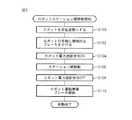
次に、図3を参照して、図1に示されているロボットシステム10のロボット24がステーション12,14間を移動する手順を説明する。
ロボットシステム10の制御装置30は、一つのステーション12又は14から他のステーション14又は12に移動する前に、作業者や安全柵18など他の機器との衝突を回避するために、ロボット24に予め定められた安全姿勢(例えば、図1に示されているようにロボットアームの関節を深く折り曲げた姿勢)とらせる(ステップS100)。次に、ロボット24の動作用モータ26への電力供給が遮断された状態でも、重力や移動時の振動などの外力によってロボット24の姿勢が変化しないように、ロボット24の各軸又は関節に機械的なブレーキをかける(ステップS102)。Next, a procedure for moving the
Prior to moving from one
次に、ロボットシステム10の制御装置30は、第2の電磁接触器42にロボット電力遮断指令を発し、電源装置34からロボット24の動作用モータ26への電力供給を遮断させ、ロボット24を動作不能にした後(ステップS104)、ロボット24の移動用モータ28に移動命令を発してロボット24を駆動させ、動作不能の状態で走行路22に沿ってロボット24を一つのステーション12又は14から他のステーション14又は12へ移動させる(ステップS106)。移動の際に、動作用モータ26への電力供給が遮断されておらずロボット24が動作可能な状態になっている又はロボット24が安全姿勢になっていないことがロボット姿勢検出装置48によって検出されたときには、上述したようにロボット24の動作用モータ26及び移動用モータ28を非常停止させるので、作業者用通路16の作業者の安全は確保される。 Next, the control device 30 of the
ロボット24が次のステーション14又は12に到達すると、制御装置30は、第2の電磁接触器42に対するロボット電力遮断指令を解除して主接点42aを閉じさせ、電源装置34から動作用モータ26への電力供給を再開させる(ステップS108)と共に、ロボット24の各軸又は関節の機械的なブレーキを解除して(ステップS110)、ロボット24を動作可能な状態にさせ、ステーション12,14間におけるロボット24の移動を完了させる。 When the
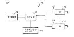
図4は、図1のロボットシステム10で使用される他の実施形態のロボット姿勢検出装置48´を示している。本実施形態のロボット姿勢検出装置48´は、CPUなどの処理装置52と、これに接続された不揮発性メモリなどの記憶装置54と、ロボット24の各軸又は関節を駆動するための動作用モータ26に取り付けられた位置検出器56と、動作信号回路46の接点50を開閉するための非常停止信号出力回路58とにより構成されている。制御装置30は、ロボット24の各軸の動作用モータ26に取り付けられた位置検出器56によって検出された角度情報に基づいてロボット24の各軸の位置(角度)や速度を制御している。すなわち、各軸の動作用モータ26に取り付けられた位置検出器56によって検出された角度情報に基づいて、ロボット24の姿勢を求めることができる。 FIG. 4 shows a robot
記憶装置54には、ロボット24が安全姿勢になるときの各軸の角度情報が記憶されており、処理装置52は、位置検出器56からの現在の各軸の角度情報と記憶装置54に記憶された安全姿勢時の各軸の角度情報とを比較し、両者の間の差異が予め定められた許容値の範囲内であるときには、ロボット24が安全姿勢にあると判断し、許容値の範囲を越えているときには、ロボット24が安全姿勢にないと判断する。そして、処理装置52は、ロボット24が安全姿勢にあると判断したときには、動作信号回路46の対応する接点50を閉じた状態のままにする。一方、ロボット24が安全姿勢にないと判断したときには、非常停止信号出力回路58により動作信号回路46の対応する接点50を開いて動作信号回路46から動作信号が出力されない状態にして、第1の電磁接触器40によって電源装置34から動作用モータ26及び移動用モータ28への電力供給を遮断させ、ロボットシステム10を非常停止状態にさせる。 The
図5は、図4に示されているロボット姿勢検出装置48´と類似の他の実施形態のロボット姿勢検出装置48″であり、CPUのような処理装置52と、それに接続される記憶装置54及び非常停止信号出力回路58が、二組設けられている点において、図4に示されているロボット姿勢検出装置48´と異なっている。二つの処理装置52は、互いの動作状態を監視しており、他方の処理装置52の異常を検出したときには、警告を行うと共に、非常停止信号出力回路58を通して動作信号回路46の接点50を開き、ロボットシステム10を非常停止させる。各処理装置52における処理内容は図4に示されている処理装置52と同様であるので、ここでは詳しく説明しない。 FIG. 5 shows a robot
このように二つの処理装置52によってロボット24の姿勢を検出すれば、一方の処理装置24が故障しても他の処理装置52によってロボット24が安全姿勢であるか否かが検出されるので、非常に信頼性の高い非常停止装置を構成することができる。また、各処理装置52に接続される記憶装置54が別個に設けられているので、より信頼性が高くなる利点も有する。なお、本実施形態において、処理装置52と、それに接続される記憶装置54及び非常停止信号出力回路58とからなる組を3組以上設けることが可能であることはいうまでもない。 If the posture of the
図4又は図5に示されているロボット姿勢検出装置48´又は48″を使用したロボットシステム10おいてステーション12,14間でロボット24を移動させるときには、ロボット24を一つのステーション12又は14から移動させる前にロボット姿勢検出装置48´又は48″の動作を開始させ、ロボット24を他のステーション14又は12へ移動させた後にロボット姿勢検出装置48´又は48″の動作を停止させればよい。これにより、ステーション12又は14内での作業中にロボット24が安全姿勢にないとしてロボットシステム10が非常停止されることが回避される。例えば、図6に示されているように、図3と同様の手順において、ロボット24の各軸に機械的なブレーキをかけるステップ(ステップS102)の後に、ロボット姿勢検出装置48又は48″の動作を開始させ(ステップS112)、ステーション12,14間でロボット24を移動させるステップ(ステップS106)の後に、ロボット姿勢検出装置48´又は48″の動作を終了させればよい(ステップS114)。図6における他の手順は図4に示されている手順と同じであるので、ここでは詳しく説明しない。 When the
以上、図示されている実施形態に基づいて、本発明のロボットシステム10を説明したが、本発明は図示される実施形態に限定されるものではない。例えば、図1に示されている実施形態では、ロボット24が走行路22の予め定められた区間内に位置することを検出するために、走行路22の予め定められた区間にわたって延びるように設けられたドグ44aとリミットスイッチ44bとが使用されているが、走行路22の予め定められた区間の両端に、ドグ又はライトカーテンなどを設けて、当該区間の境界を通過したことを検出するようにしてもよい。 Although the
また、図1の実施形態では、ライトカーテン48aが安全柵18の上縁に沿って設けられているが、安全柵18の上縁に沿って設けられたライトカーテン48aに加えて、走行路22の下方の作業者用通路16にこれを横断する方向に別のライトカーテンを設置し、作業者が走行路22の下方の作業者用通路16に侵入したことを検出できるようにし、作業者の存在を検出した場合にロボット24の動作用モータ26及び移動用モータ28を非常停止させるようにしてもよい。 In the embodiment of FIG. 1, the
10 ロボットシステム
12 第1のステーション
14 第2のステーション
16 作業者用通路
22 走行路
24 ロボット
26 動作用モータ
28 移動用モータ
34 電源装置
40 第1の電磁接触器
40a 接点
42 第2の電磁接触器
42a 主接点
42b 連動接点
44 ロボット位置検出装置
48 ロボット姿勢検出装置DESCRIPTION OF
Claims (6)
Translated fromJapanese一つのステーションから他のステーションへ前記ロボットを移動させるときに前記移動用モータへの電力供給を継続しながら前記動作用モータへの電力供給を遮断するロボット電力遮断装置と、
前記動作用モータへの電力供給の遮断状態を監視する遮断状態監視装置と、
前記動作用モータと前記移動用モータを非常停止させる非常停止装置と、
を備え、前記非常停止装置は、前記動作用モータへの電力供給が遮断されていないことが前記遮断状態監視装置によって検出されているときに前記ロボットが前記作業者用通路の上方の区間を含む前記走行路の予め定められた区間に侵入すると、前記移動用モータへの電力供給を遮断することにより前記移動用モータを非常停止させることを特徴としたロボットシステム。A traveling path extending over the plurality of stations and extending above the plurality of stations, an operating motor and a moving motor, and performing a desired operation by the operating motor and being moved to the traveling path by the moving motor. A robot horizontally moving along the robot, wherein the robot moves between the plurality of stations across an operator passage provided between adjacent stations along the traveling path.
A robot power cut-off device that cuts off power supply to the operation motor while continuing to supply power to the movement motor when moving the robot from one station to another station;
An interruption state monitoring device for monitoring an interruption state of power supply to the operation motor;
An emergency stop device for emergency stopping the operation motor and the movement motor;
The emergency stop device includes a section above the worker passage when the robot detects that the power supply to the operation motor is not cut off by the cut-off state monitoring device. A robot system characterized in that, when entering a predetermined section of the travel path, the moving motor is emergency stopped by shutting off power supply to the moving motor.
Priority Applications (4)
| Application Number | Priority Date | Filing Date | Title |
|---|---|---|---|
| JP2006344446AJP4168072B2 (en) | 2006-12-21 | 2006-12-21 | Robot system |
| US11/959,117US20080150467A1 (en) | 2006-12-21 | 2007-12-18 | Robot system able to secure worker safety |
| EP07024562AEP1935579A2 (en) | 2006-12-21 | 2007-12-18 | Robot system able to secure worker safety |
| CNA2007101597293ACN101204811A (en) | 2006-12-21 | 2007-12-21 | Robot system able to secure worker safety |
Applications Claiming Priority (1)
| Application Number | Priority Date | Filing Date | Title |
|---|---|---|---|
| JP2006344446AJP4168072B2 (en) | 2006-12-21 | 2006-12-21 | Robot system |
Publications (2)
| Publication Number | Publication Date |
|---|---|
| JP2008155298A JP2008155298A (en) | 2008-07-10 |
| JP4168072B2true JP4168072B2 (en) | 2008-10-22 |
Family
ID=39273271
Family Applications (1)
| Application Number | Title | Priority Date | Filing Date |
|---|---|---|---|
| JP2006344446AExpired - Fee RelatedJP4168072B2 (en) | 2006-12-21 | 2006-12-21 | Robot system |
Country Status (4)
| Country | Link |
|---|---|
| US (1) | US20080150467A1 (en) |
| EP (1) | EP1935579A2 (en) |
| JP (1) | JP4168072B2 (en) |
| CN (1) | CN101204811A (en) |
Families Citing this family (34)
| Publication number | Priority date | Publication date | Assignee | Title |
|---|---|---|---|---|
| US7974736B2 (en)* | 2007-04-05 | 2011-07-05 | Foster-Miller, Inc. | Robot deployed weapon system and safing method |
| DE102007028390A1 (en)* | 2007-06-15 | 2008-12-18 | Abb Research Ltd. | Process control, system and method for the automated adaptation of process parameters of at least one handling device |
| JP4291385B2 (en)* | 2007-09-27 | 2009-07-08 | ファナック株式会社 | Robot controller that stops the robot based on the speed of the robot hand |
| EP2288839A1 (en)* | 2008-06-26 | 2011-03-02 | Abb Ag | System for safety protection of human beings against hazardous incidents with robots |
| JP5308840B2 (en)* | 2009-01-21 | 2013-10-09 | ファナック株式会社 | Robot system with power supply adjustment device |
| WO2010090351A1 (en)* | 2009-02-09 | 2010-08-12 | Kawasaki Jukogyo Kabushiki Kaisha | Robot system |
| EP2429931B1 (en)* | 2009-05-15 | 2014-12-31 | Wals Systems B.V. | Packing apparatus |
| JP5755842B2 (en)* | 2010-04-22 | 2015-07-29 | 株式会社ダイヘン | Work transfer system |
| JP4938118B2 (en)* | 2010-08-17 | 2012-05-23 | ファナック株式会社 | Human cooperation robot system |
| ITMI20122179A1 (en) | 2012-12-19 | 2014-06-20 | Pirelli | METHOD TO VERIFY THE CORRECT FORMATION OF HEELS IN A PROCESS AND IN A PLANT TO PACK VEHICLE WHEELS TIRES. |
| JP2015024467A (en)* | 2013-07-26 | 2015-02-05 | セイコーエプソン株式会社 | Robot and robot emergency stop method |
| KR101532485B1 (en)* | 2013-09-17 | 2015-06-30 | 코리아에프티 주식회사 | Canister inspection equipment |
| JP5855685B2 (en) | 2014-01-30 | 2016-02-09 | ファナック株式会社 | Servo motor control device and production system provided with the control device |
| EP3113914A4 (en)* | 2014-03-04 | 2017-12-27 | Universal Robots A/S | Safety system for industrial robot |
| JP5964472B1 (en)* | 2015-02-03 | 2016-08-03 | ファナック株式会社 | Machining system with operation restriction function of robot and machine tool |
| DE102015212171B3 (en)* | 2015-06-30 | 2016-06-30 | Kuka Roboter Gmbh | Method for controlling a manipulator system |
| JP6177837B2 (en)* | 2015-06-30 | 2017-08-09 | ファナック株式会社 | Robot system using visual sensor |
| US9910186B2 (en)* | 2015-08-17 | 2018-03-06 | Rockwell Automation Safety Ag | Dynamic light curtain muting system and method |
| JP6088605B1 (en)* | 2015-08-31 | 2017-03-01 | ファナック株式会社 | Robot system using visual sensor |
| JP6474339B2 (en)* | 2015-09-01 | 2019-02-27 | ファナック株式会社 | A machine that stops the movement of members on the drive shaft due to brake abnormality |
| DE102016005026B3 (en) | 2016-04-24 | 2017-05-18 | Sami Haddadin | System and method for controlling a robot |
| EP3243609A1 (en)* | 2016-05-09 | 2017-11-15 | OpiFlex Automation AB | A fenceless industrial robot system |
| EP3541219B1 (en)* | 2016-11-16 | 2024-01-24 | Wink Robotics | Eyelid covering and stabilization for automatic eyelash extension |
| KR101785998B1 (en)* | 2017-06-26 | 2017-10-18 | 주식회사 썬에이치에스티 | Human access detecting system for preventing safety accident |
| US10782665B2 (en)* | 2017-06-30 | 2020-09-22 | Cattron North America, Inc. | Wireless emergency stop systems, and corresponding methods of operating a wireless emergency stop system for a machine safety interface |
| EP3427904B1 (en)* | 2017-07-13 | 2020-06-10 | Siemens Aktiengesellschaft | Assembly with a manipulator and a limiting device for limiting the working space |
| FR3069307B1 (en)* | 2017-07-21 | 2019-07-26 | Sidel Participations | HANDLING INSTALLATION OF SECURED MAINTENANCE ARTICLES |
| CN107492041B (en)* | 2017-07-24 | 2020-11-06 | 浙江大学 | An energy supervision system and method for the era of artificial intelligence |
| CN107838904A (en)* | 2017-11-14 | 2018-03-27 | 徐州欧普莱斯工业机械有限公司 | A kind of safety-type Pneumatic manipulator with emergency power |
| CN109079793A (en)* | 2018-09-12 | 2018-12-25 | 珠海格力电器股份有限公司 | Industrial robot safety protection device and working method thereof, industrial robot and working method thereof |
| CN110154090A (en)* | 2019-06-25 | 2019-08-23 | 深圳市三宝创新智能有限公司 | A kind of power-off posture homing device for desktop machine people |
| JP7342618B2 (en)* | 2019-10-30 | 2023-09-12 | セイコーエプソン株式会社 | Robot system and robot system control method |
| CN111564011B (en)* | 2020-07-20 | 2020-11-03 | 季华实验室 | Mechanical arm safety detection method, device and system and electronic equipment |
| EP3960669A1 (en)* | 2020-08-28 | 2022-03-02 | G.J. Hollestelle Beheer B.V. | Stack manipulating system and corresponding method |
Family Cites Families (9)
| Publication number | Priority date | Publication date | Assignee | Title |
|---|---|---|---|---|
| US4815007A (en)* | 1984-12-20 | 1989-03-21 | Seiko Epson Corporation | Apparatus for controlling a robot |
| US4890241A (en)* | 1987-10-26 | 1989-12-26 | Megamation Incorporated | Robotic system |
| JP2569297B2 (en)* | 1989-03-10 | 1997-01-08 | 川崎重工業株式会社 | Drive unit for the robot running unit |
| JPH02262987A (en)* | 1989-04-03 | 1990-10-25 | Mitsubishi Heavy Ind Ltd | Teaching device for robot of direct teaching type |
| US5327055A (en)* | 1993-03-08 | 1994-07-05 | International Business Machines Corporation | Mechanical brake hold circuit for an electric motor |
| JP3331875B2 (en)* | 1996-08-28 | 2002-10-07 | 松下電器産業株式会社 | Industrial robot safety devices |
| JP3910130B2 (en)* | 2002-09-30 | 2007-04-25 | ファナック株式会社 | Robot system |
| JP3950832B2 (en)* | 2002-10-08 | 2007-08-01 | ファナック株式会社 | Robot controller |
| JP3944156B2 (en)* | 2003-12-03 | 2007-07-11 | ファナック株式会社 | Emergency stop circuit |
- 2006
- 2006-12-21JPJP2006344446Apatent/JP4168072B2/ennot_activeExpired - Fee Related
- 2007
- 2007-12-18EPEP07024562Apatent/EP1935579A2/ennot_activeWithdrawn
- 2007-12-18USUS11/959,117patent/US20080150467A1/ennot_activeAbandoned
- 2007-12-21CNCNA2007101597293Apatent/CN101204811A/enactivePending
Also Published As
| Publication number | Publication date |
|---|---|
| US20080150467A1 (en) | 2008-06-26 |
| CN101204811A (en) | 2008-06-25 |
| JP2008155298A (en) | 2008-07-10 |
| EP1935579A2 (en) | 2008-06-25 |
Similar Documents
| Publication | Publication Date | Title |
|---|---|---|
| JP4168072B2 (en) | Robot system | |
| JP4817084B2 (en) | Motor drive system and motor control device | |
| JP5035768B2 (en) | Safety device for human robot coexistence work | |
| JP3910130B2 (en) | Robot system | |
| US10836035B2 (en) | Operation control device for movable apparatus, operation control system, and method of controlling operations by movable apparatus | |
| JP2008191823A (en) | Safety management method, safety management system and safety control equipment | |
| JPWO2004009303A1 (en) | Robot control apparatus and robot system | |
| JP7314304B2 (en) | Manufacturing equipment and transfer means | |
| JP2008307618A (en) | Robot control device | |
| US20230273603A1 (en) | System and Method for Adjusting Fail-Safe Monitoring in an Industrial Automation Plant | |
| JP2000033592A (en) | Production system | |
| JP2005151729A (en) | Control device | |
| EP0505431B1 (en) | Protection device in automatic production equipments | |
| TWM599711U (en) | Safety device of computerized numerical control machine | |
| JPH1110568A (en) | Unmanned transfer device | |
| JP3660190B2 (en) | Safety confirmation system for vast areas | |
| Khodabandehloo | Robot safety and reliability | |
| JPH04401Y2 (en) | ||
| JP7274667B2 (en) | Automated cell with automatic and manual charging | |
| EP4434688A1 (en) | Control method, robot system, and non-transitory computer-readable storage medium storing program | |
| KR100236168B1 (en) | Malfunction prevention device of fully automatic unmanned crane | |
| JP2006026818A (en) | Machine tool | |
| JPH06155341A (en) | Mobile robot | |
| Renshaw | Methods of guarding | |
| JPH0215353B2 (en) |
Legal Events
| Date | Code | Title | Description |
|---|---|---|---|
| A871 | Explanation of circumstances concerning accelerated examination | Free format text:JAPANESE INTERMEDIATE CODE: A871 Effective date:20080417 | |
| TRDD | Decision of grant or rejection written | ||
| A975 | Report on accelerated examination | Free format text:JAPANESE INTERMEDIATE CODE: A971005 Effective date:20080709 | |
| A01 | Written decision to grant a patent or to grant a registration (utility model) | Free format text:JAPANESE INTERMEDIATE CODE: A01 Effective date:20080715 | |
| A01 | Written decision to grant a patent or to grant a registration (utility model) | Free format text:JAPANESE INTERMEDIATE CODE: A01 | |
| A61 | First payment of annual fees (during grant procedure) | Free format text:JAPANESE INTERMEDIATE CODE: A61 Effective date:20080804 | |
| R150 | Certificate of patent or registration of utility model | Free format text:JAPANESE INTERMEDIATE CODE: R150 | |
| FPAY | Renewal fee payment (event date is renewal date of database) | Free format text:PAYMENT UNTIL: 20110808 Year of fee payment:3 | |
| LAPS | Cancellation because of no payment of annual fees |