JP4167860B2 - Biological light measurement device - Google Patents
Biological light measurement deviceDownload PDFInfo
- Publication number
- JP4167860B2 JP4167860B2JP2002198282AJP2002198282AJP4167860B2JP 4167860 B2JP4167860 B2JP 4167860B2JP 2002198282 AJP2002198282 AJP 2002198282AJP 2002198282 AJP2002198282 AJP 2002198282AJP 4167860 B2JP4167860 B2JP 4167860B2
- Authority
- JP
- Japan
- Prior art keywords
- light
- measurement
- wavelength
- subject
- error
- Prior art date
- Legal status (The legal status is an assumption and is not a legal conclusion. Google has not performed a legal analysis and makes no representation as to the accuracy of the status listed.)
- Expired - Fee Related
Links
Images


Classifications
- A—HUMAN NECESSITIES
- A61—MEDICAL OR VETERINARY SCIENCE; HYGIENE
- A61B—DIAGNOSIS; SURGERY; IDENTIFICATION
- A61B5/00—Measuring for diagnostic purposes; Identification of persons
- A61B5/145—Measuring characteristics of blood in vivo, e.g. gas concentration or pH-value ; Measuring characteristics of body fluids or tissues, e.g. interstitial fluid or cerebral tissue
- A61B5/1455—Measuring characteristics of blood in vivo, e.g. gas concentration or pH-value ; Measuring characteristics of body fluids or tissues, e.g. interstitial fluid or cerebral tissue using optical sensors, e.g. spectral photometrical oximeters
- A61B5/14551—Measuring characteristics of blood in vivo, e.g. gas concentration or pH-value ; Measuring characteristics of body fluids or tissues, e.g. interstitial fluid or cerebral tissue using optical sensors, e.g. spectral photometrical oximeters for measuring blood gases
- A61B5/14553—Measuring characteristics of blood in vivo, e.g. gas concentration or pH-value ; Measuring characteristics of body fluids or tissues, e.g. interstitial fluid or cerebral tissue using optical sensors, e.g. spectral photometrical oximeters for measuring blood gases specially adapted for cerebral tissue
- A—HUMAN NECESSITIES
- A61—MEDICAL OR VETERINARY SCIENCE; HYGIENE
- A61B—DIAGNOSIS; SURGERY; IDENTIFICATION
- A61B2562/00—Details of sensors; Constructional details of sensor housings or probes; Accessories for sensors
- A61B2562/02—Details of sensors specially adapted for in-vivo measurements
- A61B2562/0233—Special features of optical sensors or probes classified in A61B5/00
- A—HUMAN NECESSITIES
- A61—MEDICAL OR VETERINARY SCIENCE; HYGIENE
- A61B—DIAGNOSIS; SURGERY; IDENTIFICATION
- A61B2562/00—Details of sensors; Constructional details of sensor housings or probes; Accessories for sensors
- A61B2562/04—Arrangements of multiple sensors of the same type
- A61B2562/046—Arrangements of multiple sensors of the same type in a matrix array
- A—HUMAN NECESSITIES
- A61—MEDICAL OR VETERINARY SCIENCE; HYGIENE
- A61B—DIAGNOSIS; SURGERY; IDENTIFICATION
- A61B5/00—Measuring for diagnostic purposes; Identification of persons
- A61B5/0033—Features or image-related aspects of imaging apparatus, e.g. for MRI, optical tomography or impedance tomography apparatus; Arrangements of imaging apparatus in a room
- A61B5/004—Features or image-related aspects of imaging apparatus, e.g. for MRI, optical tomography or impedance tomography apparatus; Arrangements of imaging apparatus in a room adapted for image acquisition of a particular organ or body part
- A61B5/0042—Features or image-related aspects of imaging apparatus, e.g. for MRI, optical tomography or impedance tomography apparatus; Arrangements of imaging apparatus in a room adapted for image acquisition of a particular organ or body part for the brain
- A—HUMAN NECESSITIES
- A61—MEDICAL OR VETERINARY SCIENCE; HYGIENE
- A61B—DIAGNOSIS; SURGERY; IDENTIFICATION
- A61B5/00—Measuring for diagnostic purposes; Identification of persons
- A61B5/72—Signal processing specially adapted for physiological signals or for diagnostic purposes
- A61B5/7235—Details of waveform analysis
- A61B5/7264—Classification of physiological signals or data, e.g. using neural networks, statistical classifiers, expert systems or fuzzy systems
Landscapes
- Health & Medical Sciences (AREA)
- Life Sciences & Earth Sciences (AREA)
- Physics & Mathematics (AREA)
- Heart & Thoracic Surgery (AREA)
- Molecular Biology (AREA)
- Spectroscopy & Molecular Physics (AREA)
- Biophysics (AREA)
- Pathology (AREA)
- Engineering & Computer Science (AREA)
- Biomedical Technology (AREA)
- Neurology (AREA)
- Medical Informatics (AREA)
- Optics & Photonics (AREA)
- Surgery (AREA)
- Animal Behavior & Ethology (AREA)
- General Health & Medical Sciences (AREA)
- Public Health (AREA)
- Veterinary Medicine (AREA)
- Measurement Of The Respiration, Hearing Ability, Form, And Blood Characteristics Of Living Organisms (AREA)
- Investigating Or Analysing Materials By Optical Means (AREA)
Description
Translated fromJapanese【0001】
【発明の属する技術分野】
本発明は、光計測技術に係り、特に、生体を含む被検体内部の情報を、光を用いて計測する技術に関する。
【0002】
【従来の技術】
近赤外領域の光を用いた生体計測技術は、脳機能の計測に応用されている。特開平09−098972号公報には、2波長の光を用いて脳機能を多点同時計測する技術が記載されており、脳機能の画像計測技術として使用されている。
【0003】
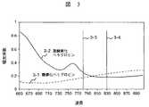
図2に示すように、頭皮2−3上から照射した光2−1を離れた地点で再び検出光2−2として検出することによって、透過光強度の変化を計測する。その変化から、照射―検出点間の大脳皮質2−5におけるヘモグロビン濃度変化を算出することが出来る。図中、2−4は頭蓋骨、2−6は計測中深部位を示す。ヘモグロビンは、酸素化状態によって酸素化ヘモグロビンと脱酸素化ヘモグロビンとに分類されるが、図3に示すように、それぞれの吸光スペクトル(吸光係数)3−1、3−2が異なっているため、異なる2波長の光を用いることにより、各ヘモグロビンの濃度変化を独立に計測することが出来る。従来は、780nm(3−3)、830nm(3−4)の波長を使用し計測することが多かった。
【0004】
酸素化ヘモグロビンおよび脱酸素化ヘモグロビン濃度変化の算出式に関しては、例えば、特開平9−19480公報や、「メディカルフィジックス(Medical Physics)、1995年、第22号,1997頁〜2005頁」に記載されている。脳の活動に伴い局所的に血液酸化状態が変化するため、この酸素化および脱酸素化ヘモグロビンの濃度変化が、神経活動を表す指標の1つとして用いられる。
【0005】
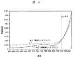
上記の生体光計測方法において、計測波長によって誤差の大きさが変化することが、「メディカルフィジックス(Medical Physics)、2001年、第28号6巻、1108頁〜1114頁」に開示されている。ここでは、一定の照射―検出間距離(30mm)の計測において、830nmと組み合わせる波長を従来の780nmより短くした場合の計測誤差について検討している。透過光強度および透過光強度に含まれる雑音の大きさが波長に依存しないと仮定した場合、780nmの波長を短くすると、脱酸素化ヘモグロビンに対する吸光係数が大きくなり、ヘモグロビン濃度変化に対する計測誤差が低減する。理論的に示される計測誤差の波長依存性を、図4に示す。横軸には、一方の計測波長を830nmに固定した場合のもう一方の計測波長を示し、縦軸には、計測誤差(雑音の振幅)を示した。また、4−3は従来多く用いられてきた波長780nmを示す。元信号(透過光信号)に含まれる雑音の大きさは各波長で一定であると仮定し、酸素化ヘモグロビンの計測誤差(点線4−1)と、脱酸素化ヘモグロビンに対する計測誤差(実線4−2)を示した。この理論的予測の妥当性は、頭頂部の計測(被検体数=1)で確認されている。
【0006】
以上のように、従来の計測装置で多く用いられてきた780nmの光を短波長化することにより、計測誤差が小さくなる傾向が知られている。
【0007】
生体光計測に適した波長の選択方法としては、例えば、特開平7−222736号公報に記載されている。ここでは、反射光ではなく生体中を通過した光を測定する計測法において、測定対象の大きさ、つまり照射−検出間距離を考慮した波長の選択方法が提案されている。選択基準となる条件は、「ヘモグロビンの酸素化状態を精度よく計測する」という条件と「充分な通過光量を得る」という、下記に示す2点である。
【0008】
▲1▼酸素化ヘモグロビンの吸収量と脱酸素化ヘモグロビンの吸収量の差が大きい波長の方が、ヘモグロビン酸素化状態の変化を精度よく検出できる。従って、600nm台の短い波長域が適している。
【0009】
▲2▼充分な通過光量を検出するためには、生体に対する光透過性の高い波長が必要である。従って、700nm後半〜900nmの長波長域が適している。
【0010】
上記各条件を満たす波長域は異なっているため、上記の公知例では通過光量を変化させる一つの要因「照射−検出間距離」に応じて、両条件を考慮して照射−検出間距離に合わせた最適波長を選択する方法が開示されている。
【0011】
【発明が解決しようとする課題】
生体内部の情報を反射光によって計測する方法においては、同じ深部を計測する必要があり、また、複数の計測点を設けて画像化する場合もあるため、照射―検出間距離を一定にした計測方法が採られる。従って、照射―検出間距離の変化に応じて波長を選択する従来技術では、常に一定の計測波長を用いていた。
【0012】
しかし、様々な部位を計測した結果、同じ照射―検出間距離の計測でも、組織構造が異なる部位では計測誤差の低減に適した波長が異なる。830nmと組み合わせる波長を短く変化させた場合、ある値の波長までは計測誤差が漸次低減するが、ある値の波長を境に増加に転じる。
【0013】
例えば、骨や皮膚に代表される生体の組織は、それぞれが異なる光特性(光吸収・光散乱係数)を持つことが知られている。また、人間の頭部は部位によって骨や皮膚、筋肉層の厚さが異なっており、部位毎に光特性が異なる。そのため、照射−検出間距離に合わせて波長を選択する方法では、高精度の信号を得ることが出来ないという問題があった。
【0014】
そこで、本発明は、照射−検出間距離が一定の場合でも、計測誤差をさらに低減し得る生体光計測技術を提供することを目的とする。
【0015】
【課題を解決するための手段】
上記目的を達成するために、本発明では、異なる波長を持つ複数の光源から、計測する被検体(生体)部位の組織構造及び光特性に応じた波長の光源を選択する。もしくは、任意の波長を照射できる波長可変光源を備え、計測する生体部位の組織構造及び光特性に応じた波長を選択するよう構成する。
【0016】
図1は、本発明の基本概念を示す。被検体の計測部位を分類し、その分類に応じて異なる計測波長を設定する。被検体として、頭部を例に説明すると、例えば、頭部を頭頂部1−1、前頭部1−2、側頭部1−3、後頭部1−4の4つの部位に分類し、波長選択システム1−6においてそれぞれの組織構造に応じた波長を設定しておく。計測の際には、各計測部位に応じた波長を多波長光照射手段1−5により選択する。
【0017】
選択した波長の光を、複数の計測点に応じて信号を分離できるよう各位置所定の周波数で変調し、それぞれの光結合器に送信する。各光結合器では、異なる波長の光信号と混合され、照射用光ファイバに送信される。混合される波長は、異なる波長を持つ複数の光源から選択された波長、もしくは波長可変光源によって選択された波長、もしくは固定の光源から照射される一定の波長とする。
【0018】
照射用光ファイバからの混合光を生体に照射し、生体からの透過光信号を検出用光ファイバで検出する。検出された光信号を電気変換後、選択された光信号用の変調周波数で復調器により信号検出する。これらの信号を記録し、ヘモグロビン濃度変化を算出する。その変化に基づいて、脳活動を示す画像を取得する。
【0019】
なお、より正確に波長を設定する場合には、人種・年齢・性別など、他の生体特性を考慮して決定することもあり得る。
【0020】
また、本発明では、本計測の前に異なる波長を持つ複数光源を用いてテスト計測を行い、ヘモグロビン濃度変化に対する誤差を算出し、その誤差の大きさに基づき波長を選択するよう構成する。生体に対する透過率の観点から、事前テスト計測には600nm〜900nmの波長を用いる。
【0021】
複数の計測点で事前テスト計測を行う場合、光はそれぞれの計測点に応じた所定の周波数で変調され、光結合器に送信される。混合された光信号は、光照射用光ファイバに送信され、計測部位に照射される。計測部位からの光信号を検出用光ファイバで検出し、電気変換した後、選択された光信号用の変調周波数を利用して復調器により信号検出する。検出された光信号から、それぞれの波長組み合わせにおけるヘモグロビン濃度変化およびその誤差を算出する。誤差の大きさを比較することによって、本計測に用いる波長を選択する。
【0022】
事前テスト計測の結果から選択された波長の光は、複数の計測点に応じて信号を分離できるよう各位置所定の周波数で変調し、それぞれの光結合器に送信する。各光結合器では、異なる波長の光信号と混合され、照射用光ファイバに送信される。混合される波長は、異なる波長を持つ複数の光源から選択された波長、もしくは波長可変光源によって選択された波長、もしくは固定の光源から照射される一定の波長とする。照射用光ファイバからの混合光を生体に照射し、生体からの透過光信号を検出用光ファイバで検出する。検出された光信号を電気変換後、選択された光信号用の変調周波数で復調器により信号検出する。これらの信号を記録し、ヘモグロビン濃度変化を算出する。その変化に基づいて、脳活動を示す画像を取得する。
【0023】
本計測の前にテスト計測を行う効用は、以下のとおりである。多波長を用いた計測では、記録・処理するデータ量も波長の数に応じて増えるため、コストが増大する。したがって、短時間の事前テスト計測の結果から使用する波長を選択し、最小限の波長数にすることでコストの低減を実現することが出来る。また、更にコストを低減するためには、事前テスト計測を全計測点ではなく代表的な計測位置だけで行うことも可能である。
【0024】
以下に、本発明による計測する生体部位に応じて異なる波長を選択する理由について述べる。
【0025】
様々な部位を計測した結果、計測誤差の低減に適した波長は、計測する生体部位によって異なることを見出した。ある部位で計測誤差が増加した波長を検討すると、透過光強度は弱まり、雑音が大きくなっていた。短波長化に従い全ヘモグロビンの吸収が強まったため、皮膚や頭蓋骨、脳内での光吸収量が増加し、検出される透過光強度が減衰したと考えられる。透過光強度の弱まりに応じて信号増幅器による増幅率を上げるため、検出される透過光強度に含まれる装置系雑音も大きくなる。つまり、透過光強度の雑音が短波長化に従い増大してしまうため、実際の計測誤差は短い波長ほど理論曲線(先述した図4)から外れる傾向を持つ。従って、最終的な計測誤差の低減効果は、各波長の吸光係数によって決定される理論的な計測誤差と、計測部位によって異なる実際の透過光強度に含まれる雑音の両方によって、決定される。
【0026】
以上のように、同じ照射−検出間距離であっても、計測誤差を低減させる波長を一律には選択できないことが分かった。照射−検出間距離に応じて波長を設定する従来の方法では、同じ照射−検出間距離であれば常に一定の波長を用いることしか出来なかった。そのため、例えば、その照射−検出間距離で計測誤差の低減が予測された波長を用いても、透過光強度に含まれる雑音が吸光係数から予測された計測誤差の低減効果を上回り、誤差が増大する場合があった。また、逆に、透過光強度に含まれる雑音が小さい場合には、計測誤差を更に低減させる波長が使用可能であっても、照射−検出間距離に応じた波長しか選択されなかった。
【0027】
骨や皮膚に代表される生体の組織は、それぞれが異なる光特性(光吸収・光散乱係数)を持つことが知られている。人間の頭部は部位によって骨や皮膚、筋肉層の厚さが異なっており、部位毎に光特性が異なることを見出した。従って、同じ波長の光を照射しても、計測部位によって透過光強度および透過光強度に含まれる雑音が異なる。計測部位によって計測誤差の低減に適した波長域が異なるため、照射−検出間距離が一定の場合でも、計測部位の違いを考慮した波長選択方法が必要になる。
【0028】
また、計測部位によっては個人差が大きく、同じ部位を同じ波長で計測しても、誤差が低減する場合としない場合とが混在した。先述の特開平7−222736号公報には、事前に透過光強度を計測し使用する波長を選択する方法が記載されているが、透過光強度によりその波長を用いた計測が可能かどうか判断するだけであった。計測対象であるヘモグロビン濃度変化に対する計測誤差には、その波長のヘモグロビン吸光係数と、透過光強度に含まれる雑音の大きさの両方が影響するため、透過光強度だけを基準にした波長の評価は不充分である。
【0029】
そのため、例えば、計測には不充分だと判断された透過光強度の波長であっても、吸光係数による誤差の低減効果が大きく計測精度が良くなる場合が存在した。このような場合には、透過光強度だけではなく、透過光強度信号に含まれる雑音の大きさと、計測波長の吸光係数から予測される計測誤差の両方を考慮した波長選択方法が重要となる。
【0030】
このように、本発明では、照射−検出間距離が一定の場合でも、組織構造の違いに起因する光特性の違いを考慮して、各計測部位に応じた波長を選択し得る計測技術を実現し、また、計測対象であるヘモグロビン濃度変化に対する計測誤差を基準にして波長を選択し得る生体光計測技術を実現する。
【0031】
【発明の実施の形態】
以下、本発明の実施例について、図面を参照して詳述する。
【0032】
(実施例1)
本発明の第1の実施例を、図5に示す装置構成に従い、説明する。本実施例の装置は、パーソナルコンピュータやワークステーション等に代表される電子計算機から構成される制御装置5−3と、波長の異なる複数の光源(本実施例では、それぞれ波長の異なる4個の光源、光源5−5(678nm)、光源5−6(692nm)、光源5−7(780nm)、光源5−8(830nm))と、上記複数の光源を異なった周波数で変調する変調器5−4と、ケーブル5−10を通して上記制御装置5−3から伝えられる命令により制御される光選択スイッチ5−9と、上記変調器5−4により変調された1波長(本実施例では、光源5−8(830nm))の光と上記光スイッチ5−9により選択された波長の光を結合する光結合器5−11と、上記光結合器5−11からの光を光照射用光ファイバ5−13を通して被検体5−18の頭皮上の異なる位置に照射する複数の光照射手段と、上記複数の光照射手段の光照射位置から等距離(本実施例では、30mmとする。)の位置に先端が位置するよう設けられた複数の光検出用光ファイバ5−14とそれぞれに設けられた光検出器5−12からなる複数の受光手段と、上記変調器5−4からの変調周波数が参照信号として入力されるロックインアンプ5−1とを備える。
【0033】
本実施例では、複数の光信号を1点から検出しているが、変調器を用いることによって、どの照射位置からの信号かを区別している。このように複数の光信号を分離する方法以外にも、変調器は使わずにパルス光を用いて、点灯タイミングで光信号を分離することも可能である。
【0034】
また、一方の波長のみを複数の光源から選択しているが、両方の波長を複数光源から選択することも可能とする。
【0035】
図中、被検体5−18上に示した白丸(○印)および黒丸(●印)は、各々、光照射用の光ファイバを配置する光照射位置(本実施例では、計4箇所)および光検出用の光ファイバを配置する光検出位置(同、5箇所)であり、交互に配列される。光照射位置と隣り合った光検出位置の各略中点を各計測位置5−15とする(同、12箇所)。
【0036】
図5には、一つの計測位置5−15における計測の装置構成のみ枠内5−16に記したが、他の計測位置でも同様に計測される(例えば、枠5−16の中身は枠5−17と同じ構成となる。)。
【0037】
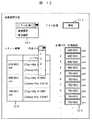
本実施例では、被検体を部位により分類し、それぞれの部位に応じて波長組み合わせを制御装置で選択する。図6に、実験者が操作する制御装置のインターフェース画面の1例を示した。プルダウンメニュー6−1から「部位選択」を選択すると、被検体分類6−2および計測部位分類6−3を設定するラジオボタンが表示される。被検体および計測部位に応じて該当箇所をチェックすると、一定の規則に従い計測対象に最適な波長が選択され、表示部6−4に表示される。例えば、「成人」「側頭部」を選択すると「692/780nm」の光が選択される規則などである。
【0038】
この選択規則は、核磁気共鳴画像法等を用いて、データベースとなる研究を元に設定したり、実験者の経験的な知見やシミュレーション結果から任意に設定したりすることが出来る。設定は、ソフト開発者のみが行える場合と各ユーザーが任意に行える場合の両方が可能である。
【0039】
また、図7に示すように、プルダウンメニュー7−1から例えば「部位選択」選択し、ラジオボタン7−2により「成人」を設定して、個々の計測チャンネル毎にプルダウンメニュー7−3から計測部位を入力し、表示部7−4においてそれぞれ適した波長を設定することも可能である。ある程度広い部位を計測する場合には、このように計測チャンネル毎に異なる波長を設定する必要がある。
【0040】
制御装置により決定された波長は、ケーブル5−10を介して波長選択スイッチ5−9に伝えられ、選択される。結合器5−11において、830nmの光5−8と混合された後、その混合光は上記の光照射手段5−13より所定の光照射位置に照射される。隣の光検出位置から光検出用ファイバ5−14で集光された生体透過光は、光検出器5−12によって光電変換される。上記受光手段は被検体内部で反射して戻ってきた光を検出し電気信号に変換するためのもので、例えばアバランシェフォトダイオードに代表される光電変換素子を用いる。光検出器で光電変換された透過光信号は、それぞれロックインアンプ5−1に入力される。 ここで、各光検出器5−12は、検出器から等距離にある複数の照射点からの入射光を検出し、更にそれぞれの入射光は異なる2波長が混合されているため、各計測位置および波長毎に透過光信号を分離する必要がある。ロックインアンプ5−1には、各変調器5−4からの変調周波数が参照周波数として入力されているため、個々の光源に対応した生体透過光強度を分離し、出力することができる。
【0041】
ロックインアンプの出力である分離された各波長の透過光信号は、アナログ−デジタル変換器5−2でアナログ−デジタル変換された後、制御装置5−3に入力され記憶される。この透過光信号を元に各計測部位におけるヘモグロビンの濃度変化が算出され、画像化される。
【0042】
なお、詳細な信号処理過程に関しては、特開平9−19480号公報や、「メディカルフィジックス(Medical Physics)、1995年、第22号,1997頁〜2005頁」などに記載されている。
【0043】
以上のように、本実施例では、計測対象を部位により分類し、それぞれの分類における標準的な透過光強度および各波長のヘモグロビン吸光係数を考慮して波長を選択する。そのため、算出された各ヘモグロビン濃度変化に対する計測誤差は、従来と比べて小さくなる。
【0044】
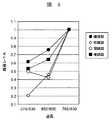
この実施例の有効性を、図8に示す。これは、計測精度を計測誤差(刺激がない状態におけるヘモグロビン変化の標準偏差)で評価し、計測波長に依存した計測精度の変化を示した図である。ここでは、多点同時計測による画像化技術を前提としており、測定サイズを30mmに統一し計測した。4箇所の計測部位(頭頂部・前頭部・側頭部・後頭部)において、従来多く用いられてきた波長組み合わせ(780/830nm)と、理論的に計測誤差の低減が予測された波長組み合わせ(678/830nm、692nm/830nm)を同時に用いて計測を行った。脱酸素化ヘモグロビンを対象に、780/830nmの波長を用いた計測における計測誤差を1として、各計測波長による計測誤差を相対的な値で示した。
【0045】
その結果、頭頂部・前頭部・後頭部においては計測波長が短くなるにつれて計測誤差が減少する傾向を示した。しかし、側頭部に関しては、692/830nmで極小値を示して678/830nmでは逆に大きくなった。この傾向は、複数の被検体で一致しており、典型的パターンの一つと考えられる。従って、標準的な選択基準を「頭頂部・前頭部・後頭部は678/830nm、側頭部は692/830nm」と設定しておけば、従来の計測波長780/830nmより精度が向上する。
【0046】
本実施例に示した被検体群が代表的被検体であり、且つ個人差は小さいと仮定すると、上記のような選択基準が出来る。本発明の装置を使わずに計測精度を向上させる標準波長を一律に決めた場合、計測部位によっては最適な波長を設定できない。例えば、前頭部を基準に選択して「678/830nm」を標準的な波長として装備してしまうと、側頭部の計測においては最適な波長を用いることが出来なくなる。このような観点から、計測部位に応じて波長を選択することの有効性は高い。
【0047】
上記の計測例は、限定された波長を用いて特定の被検体群で検討した例なので、適切な波長や計測部位の分類は必ずしもこの通りではない。計測誤差を小さくする波長は、各計測部位の吸光係数、つまり組織構造の違いに依存するため、被検体群や計測部位の分類方法の違い、あるいは用いる波長の違いによって適切な選択基準が異なる場合が考えられる。また、計測誤差を小さくする波長は透過光強度に依存することから、照射光自体の強度によっても選択基準は変化する。
【0048】
上記例の重要なことは、同じ照射−検出間距離の計測においても計測誤差を小さくする計測波長は計測部位によって異なるため、計測部位に応じて波長を選択することによって効果的に計測精度を向上させることが可能であるという点である。
【0049】
(実施例2)
本発明の第2の実施例は、光源の選択機能以外は実施例1と共通である。実施例1との相違点を、図9に示す装置構成に従い説明する。
【0050】
本実施例の装置では、波長を選択する光スイッチを用いない。9−5、9−6、9−7、9−8に示したような複数の波長の光を結合器9−11で結合した後、実施例1と同様に計測を行う。各波長の光信号は分離して計測するため、計測後に複数の波長組み合わせによるデータを取得できる。それらのデータから、計測位置毎に適切なデータを選択する。または、複数のデータを使い平均化するなど、より安定したデータを取得する。
【0051】
図9に示す装置では、波長を選択することなく候補となる波長組み合わせを全て使い計測するため、事前に波長を選択する必要がない。従って、部位からだけでは予測不能な個人差などを計測後に確認することが出来る。また、複数の波長組み合わせのデータを用いた信号安定化が可能となる。本実施例では、各光信号を変調器で周波数変調することによって計測位置に応じて複数の光信号を分離しているが、変調器は使わずにパルス光を用いて点灯タイミングで光信号を分離することも出来る。
【0052】
(実施例3)
本発明の第3の実施例は、光源以外は実施例1と共通である。実施例1との相違点を、図10に示す装置構成に従い説明する。
【0053】
本実施例の装置で用いる光源は、波長を自由に変化させることが出来る波長可変光源10−5である。制御装置10−3で計測波長が決定され、その命令がケーブル10−10を介して伝えられると、その命令に従い波長が設定される。任意の波長を設定した2つの波長可変光源10−5を、結合器10−11で結合し、実施例1と同様に計測を行う。もしくは任意の波長を設定した波長可変光源と特定の波長を持つ固定光源の2波長を結合し、計測を行うことも可能とする。
【0054】
図10の装置では、各光信号を変調器で周波数変調することによって、計測位置に応じて複数の光信号を分離している。しかし、変調器は使わずにパルス光を用いて、点灯タイミングで光信号を分離することも出来る。
【0055】
本実施例の効果は実施例1と共通だが、連続的に波長を変化させて設定することが可能であるため、限界近くまで計測誤差を低減させることが出来る。更に、1台の装置であらゆる年代・人種の被検体に対する計測を可能とする。
【0056】
(実施例4)
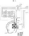
本発明の第4の実施例は、装置構成の一部と選択波長の設定方法以外は、実施例1と共通である。実施例1との相違点を、図11に示す装置構成に従い説明する。
【0057】
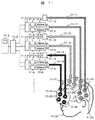
本実施例の各光照射手段は、それぞれ2波長の光源を備え、予め定められた波長組み合わせを照射する。例えば、光照射用光ファイバ11−12を含む光照射手段で照射される光は692nmと830nmの混合光、光照射用光ファイバ11−14を含む光照射手段で照射される光は780nmと830nmの混合光、光照射用光ファイバ11−16を含む光照射手段で照射される光は678nmと830nmの混合光となる。また、かかる光照射手段に対応して、それぞれ光検出用光ファイバ11−11、11−13、11−15を含む光検出手段が装備される。このように、各光照射手段が異なる波長の光を照射できる装置構成を用いて、複数種類の波長組み合わせを使用できるようにした。
【0058】
実施例1と同様に、計測部位によって波長組み合わせを選択する。具体的な波長設定方法が実施例1と異なり、計測部位に応じた波長の照射用光ファイバを手動で設定する。例えば、照射する波長によって各光ファイバの色を変え、被検体11−18の頭部に装着する各計測部位用のヘルメット11−17、11−23、11−26上のファイバ固定具(11−19、11−20;11−21、11−22;11−24、11−25)も、該当する波長の光ファイバと同じ色で着色する。このように選択する光ファイバを区別し易くすると、計測部位毎に決められた光ファイバを正しく装着することが容易になる。
【0059】
以上のように、本実施例では異なる波長光を照射する複数の光照射手段から、各計測部位に応じた波長を照射する光ファイバを手動で選択する。この方法により、実施例1と同様に各ヘモグロビン濃度変化に対する計測誤差を従来方法より小さくすることが可能である。また、実施例1と比べて、ひとつの照射手段には2つの光源しか装備しないため、波長を切り替える必要がなく、少ないコストで実施可能である。
【0060】
(実施例5)
本発明の第5の実施例の装置構成および全般的な計測方法は、実施例1で説明した図5と共通であるため、省略する。以下に、実施例1とは異なる波長選択方法について説明する。
【0061】
本実施例では、装備された波長の中から最も計測誤差を小さくする波長を制御装置5−3で判断し選択する。具体的には、装備された全ての波長を用いて事前テスト計測を行い、算出されたヘモグロビン濃度変化に対する計測誤差が最も小さくなる波長組み合わせを各計測位置で設定する。
【0062】
図12に、実験者が操作する制御装置のインターフェース画面例を示した。プルダウンメニュー12−1から「テスト計測」を選択すると、テスト計測開始ボタン12−3が表示される。計測前にテスト計測を実行すると、各波長組み合わせにおける計測誤差の大きさが12−2に、また、選ばれた最適波長が12−4に表示される。
【0063】
選択された計測波長は光スイッチ5−9によって設定され、各計測部位へ照射される。この方法は、透過光強度自体ではなく算出したヘモグロビン濃度変化の計測誤差を評価するため、透過光信号の減衰及び各波長の吸光係数の両方を考慮した総合的な判断が可能である。また、適切な波長が分からない場合や部位選択方法ではうまく行かない場合に探索的に用いることができる。
【0064】
この方法で波長を選択した場合、同時に図6や図7の部位選択方法で示したような部位の分類を入力することによって、そのデータをデータベースとして蓄積することが出来る。そのデータベースを部位選択方法の選択基準に反映させることにより、部位選択方法の信頼性が継続的に向上する。前述の実施例1と同様に、この事前テスト計測による結果も計測チャンネル毎に算出し、それぞれに適した波長を選択することが可能である。
【0065】
本実施例の効果は、図8および図14の計測例から示される。実施例1、2で示した波長選択方法は、被検体間で傾向が一致している計測部位では有効だが、計測部位によっては被検体間で傾向が異なるため、本実施例を用いた方が良い場合がある。例えば、図14に示した被検体では、頭頂部と後頭部では678/830nmにおける計測誤差が692/830nmより大きくなっており、図8で示した被検体とは異なった傾向を示した。このように、計測誤差を小さくする波長の傾向が被検体間で異なる頭頂部と後頭部においては、事前テスト計測の結果から計測波長を選択する方法が有効であると考えられた。
【0066】
また、多点を同時に計測し、課題に応じた長さの計測を繰り返し行う本計測に対し、事前テスト計測では、多点を計測する必要はなく、計測時間も短時間で充分である。従って、本計測まで多波長で計測する方法と比較した場合、事前テスト計測によって使用波長を限定する方法はコスト面で優れている。つまり、記録・処理するデータが少なくて済むため、制御装置に対する負担が小さい。
【0067】
計測対象を計測部位によって分類しなくても、事前テスト計測を用いると図8および図14に示したような各波長組み合わせにおける計測誤差が算出され、計測誤差を小さくする波長組み合わせを選択することが出来る。従って、図8の被検体を計測した場合では、頭頂部・前頭部・後頭部には678/830nmの計測波長を選択し、側頭部を計測した場合には692/830nmを選択する。また、図14の被検体では前頭部を計測した場合は678/830nmの計測波長を選択し、頭頂部・側頭部・後頭部を計測した場合は692/830nmを選択する。このように、部位選択方法では対応できない場合にも計測波長を設定することが出来る。
【0068】
この選択方法は、計測対象を正確に分類できない場合や、部位選択法により選択された波長が適切でない場合も含め、殆どの場合に有効である。例えば、毛根の太さや皮膚の色など、個人差が大きく実際に計測しなければ知る事の困難な要因を考慮し、適切な波長を選択することが出来る。
【0069】
(実施例6)
本発明の第6の実施例は、波長の決定のための事前テスト計測用の光照射検出手段と、この事前テスト計測等で使用する光の波長の組が定まったとき選択的に使用する複数組の本計測用の光照射検手段、光検出手段を有する。
【0070】
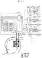
図13に、その構成を示す。事前テスト計測用の光照射検出手段13−16の内部構成は図9のブロック9−16と同様であり、同一部分には図9と同一符号を付してある。この例でも候補となる波長の組み合わせは678/830nm、692、/830nm、780/830nmである。これら波長の光を全て用いてテスト計測をするために複数の光源9−5、9−6、9−7、9−8を備え、各光源は変調器9−4で異なった周波数で変調される。光結合器9−11で混合され、光照射用光ファイバ9−13で照射位置に導かれた照射光による検出信号は、ロックインアンプ9−1で波長毎の検出信号に分離される。分離された各検出信号はアナログ−ディジタル変換器13−7を介して制御装置13−8に取り込まれる。
【0071】
本実施例では、事前テスト計測用の光照射検出手段13−16は一組だけ備えるので、被検体13−18の代表的計測位置13−20を選んでテスト計測を行うことになる。光検出器9−12の数を増やし、あるいは更にテスト用の光照射手段の数も増やす変形、つまり複数の計測点でテスト計測を行うことができるようにする変形も可能である。前述の実施例5と同様に、事前のテスト計測で得た複数波長の検出信号からそれぞれの波長の組み合わせによる計測誤差を算出し、計測誤差が最も小さい波長の組み合わせを選択する。
【0072】
本実施例は、上述の候補となる波長の組み合わせ毎にそれぞれ専用に、計測用の光照射手段を備える。678/830nmの計測のため光照射手段13−21は変調器13−10、678nm光源13−11、830nm光源13−14、および光結合器13−15を含む。また、これに対応して光検出器13−22とロックインアンプ13−9を含む光検出手段を備える。692/830nmの計測のための光照射手段13−23、及び780/830nmの計測のための光照射手段13−25も同様に構成されている。ただし光源13−12は692nm、光源13−13は780nmの波長のものである。図は略してあるが、波長の組み合わせ毎に、それぞれ光照射位置の数だけ光照射手段がある。同様に、波長の組み合わせ毎に、それぞれ光検出位置の数だけ光検出手段があり、全てのロックインアンプの出力はアナログ−ディジタル変換器13−7を介して制御装置13−8に接続されている。
【0073】
上述の事前のテスト計測により本計測での波長の組み合わせが決まると、被検体13−18に装着するファイバ固定具に固定された光ファイバを、対応する光照射手段および光検出器にそれぞれ接続する。以上で、選択した波長の組み合わせによる計測が可能となる。
【0074】
本実施例では、多波長光の混合機能とそれに対応する分離機能を備える特殊なテスト計測用の光照射検出手段の数が少数であり、本計測用の光照射手段、光照射手段は2波長混合、2波長分離という従来どおりの構成でよい。よって、装置コストの上で有利である。また、本計測用の光照射手段の構成を更に変形し、図5に示す光スイッチで波長が選択可能な光照射手段を採用することも可能である。この変形では装置トータルの光源の数が減る。また、光ファイバの接続は固定したままで、光スイッチの操作で波長の選択が完了するので、装置操作がより簡便となる利点をも有する。
【0075】
(実施例7)
本発明の第7の実施例の装置構成および全般的な計測方法は実施例1と共通であるため、省略する。以下に、実施例1とは異なる波長選択方法についてのみ説明する。
【0076】
本実施例では、候補となる複数の計測波長組み合わせから、任意の波長を実験者が直接選択する。図15に、実験者が操作する制御装置のインターフェース画面を示した。プルダウンメニュー15−1から「直接選択」を選択すると、選択できる複数の波長組み合わせが表示される。用いる波長組み合わせの左にあるラジオボタン15−2をチェックすることによって、その波長組み合わせが採用される。
【0077】
また、図16に示すように、プルダウンメニュー16−1から「直接選択」を選択すると、個々の計測チャンネル毎のプルダウンメニュー16−2より計測波長を選択し、設定することも可能である。実施例1と同様に、決定された波長は波長選択スイッチ5−9によって設定され、結合器5−10に入る。あるいは、実施例3と同様に波長可変光源10−5によって適切な波長が設定され、結合器10−7に入る。部位選択を適用できない場合や事前に適切な計測波長が分かっている場合、あるいは何らかの理由で特定の計測波長を使いたい場合に有効である。
【0078】
また、図11や図13に示したような固定の波長を照射する光照射手段および光検出器を複数種類備えた装置構成においては、任意の光照射手段を手動で選択することも出来る。
【0079】
以上の詳述した実施例に関し、波長設定方法の各選択過程をフローチャートとして、図17、図18、図19に示した。
【0080】
図17は、本発明の実施例1、2、3、5、7に関する波長選択アルゴリズムを示すフローチャートで、選択した波長の設定を制御装置により行う場合を示す。
【0081】
図18は、実施例4、6、7に関する波長選択アルゴリズムを示すフローチャートで、選択した波長の設定を手動で行う場合を示す。
【0082】
また、図19は、計測波長を設定した後の本計測の流れを示したものである。
【0083】
以上詳述したように、本発明は、生体光計測において、計測部位に応じて波長を設定でき、また、各計測位置の透過光信号に含まれる雑音とヘモグロビン吸光係数に依存した最終的な計測誤差に応じて波長を設定できるため、最大限に計測誤差を低減させることが出来る。従来の計測方法より信号検出力が高まるため、雑音の除去に必要な加算平均の回数が減り、計測時間の短縮・被検体への負担軽減などの効果が得られる。また、多点同時計測を用いた画像計測、特に全脳を計測する装置においては、各計測位置に応じて波長を選ぶことが出来るので、全体の誤差のばらつきが最小限になるよう波長を選択する事が出来る。各計測点のS/Nを揃えることによって、異なる計測位置の信号を比較することが可能となる。
【0084】
以下に、本発明に含まれる構成例を列挙する。
【0085】
(1)被検体へ光を照射する光照射手段と、前記光照射手段から照射され前記被検体内を伝播した通過光を検出する受光手段とを被検体上に配置し、前記受光手段によって検出された信号に基き、前記光照射手段と前記受光手段の略中点位置を計測点として被検体内の情報を計測するよう構成した生体光計測装置において、前記光照射手段が、それぞれ異なる波長を持つ複数の光源を有し、かつ、前記複数の光源から前記被検体における計測部位の組織構造および光特性に応じた波長をもつ光源を選択し、計測するよう構成したことを特徴とする生体光計測装置。
【0086】
(2)前記(1)記載の生体光計測装置において、前記波長の選択は、計測対象を前記計測部位によって分類し、前記計測部位毎に予め設定した波長から選択するようにしたことを特徴とする前記(1)記載の生体光計測装置。
【0087】
(3)前記(1)記載の生体光計測装置において、前記波長の選択は、複数の計測波長を用いて予めテスト計測を行い、計測対象信号に対する誤差を算出して、その誤差の大きさに基づき波長を選択するようにしたことを特徴とする生体光計測装置。
【0088】
(4)前記(1)記載の生体光計測装置において、予め設定した基準に従い計測対象に応じた波長選択方法を表示する表示部を設けてなることを特徴とする生体光計測装置。
【0089】
(5)前記(1)記載の生体光計測装置において、前記光照射手段が、任意の波長の光を照射できる波長可変光源を有し、前記複数の光源および前記波長可変光源のうちいずれかの光源を選択することにより、前記被検体における計測部位の組織構造および光特性に応じた波長を選択し得るよう構成したことを特徴とする生体光計測装置。
【0090】
(6)被検体へ光を照射する光照射手段と、前記光照射手段から照射され前記被検体内を伝播した通過光を検出する受光手段とを被検体上に配置し、前記受光手段によって検出された信号に基き、前記光照射手段と前記受光手段の略中点位置を計測点として被検体内の情報を計測するよう構成した生体光計測装置において、前記光照射手段が、任意の波長の光を照射できる波長可変光源を有し、かつ、前記被検体における計測部位の組織構造および光特性に応じて前記光源の照射光の波長を選択するよう構成したことを特徴とする生体光計測装置。
【0091】
(7)前記(6)記載の生体光計測装置において、前記波長の選択は、計測対象を前記計測部位によって分類し、前記計測部位毎に予め設定した波長から選択するようにしたことを特徴とする生体光計測装置。
【0092】
(8)前記(6)記載の生体光計測装置において、前記波長の選択は、複数の計測波長を用いて予めテスト計測を行い、計測対象信号に対する誤差を算出して、その誤差の大きさに基づき波長を選択するようにしたことを特徴とする生体光計測装置。
【0093】
(9)前記(6)記載の生体光計測装置において、予め設定した基準に従い計測対象に応じた波長選択方法を表示する表示部を設けてなることを特徴とする生体光計測装置。
【0094】
(10)前記(6)記載の生体光計測装置において、前記光照射手段が、それぞれ異なる波長を持つ複数の光源を有し、前記波長可変光源および前記複数の光源のうちいずれかの光源を選択することにより、前記被検体における計測部位の組織構造および光特性に応じた波長を選択し得るよう構成したことを特徴とする生体光計測装置。
【0095】
(11)被検体の所定の照射位置へ光を照射する工程と、前記被検体内を伝播した通過光を所定の受光位置で検出する工程と、検出された信号に基き、前記被検体上の前記光照射位置と前記受光位置の略中点位置を計測点として前記検体内の情報を計測するよう工程とを有し、前記被検体への光照射を、異なる波長の光を照射できる複数の光源もしくは任意の波長の光を照射できる波長可変光源を用いて行い、かつ、前記複数の光源もしくは前記波長可変光源から、前記被検体における計測部位の組織構造および光特性に応じた波長を選択し計測するよう構成したことを特徴とする光計測方法。
【0096】
(12)被検体内部の情報を光を用いて測定する装置に関して、計測部位の組織構造の違いに応じて、その部位の光特性に合わせた波長を選択し計測する生体光計測装置。
【0097】
(13)被検体に可視から近赤外領域までの波長の光を照射する複数の光照射手段と、上記光照射手段から照射され、上記被検体内部で通過した光を検出する複数の受光手段と、上記受光手段で検出された信号を複数の受光手段毎にかつ経時的に記憶する記憶手段と、上記記憶手段に記憶された信号を用いて複数の計測点毎に計測対象の信号に変換する演算手段と、上記演算手段の出力を推定測定点の信号として求め二次元表示面に強度信号として画像表示する画像作成部を持つことを特徴とする生体光計測装置において、計測部位の組織構造の違いに応じて、その部位の光特性に合わせた波長を選択し計測する生体光計測装置。
【0098】
(14)前記(12)および(13)に関して、計測対象を部位によって分類し、その部位毎に予め設定した波長の光を選択し照射する生体光計測装置。
【0099】
(15)前記(12)および(13)に関して、複数の計測波長を用いた事前テスト計測を行い、計測対象信号(例: 酸素化ヘモグロビン)に対する誤差を評価し、その値を基準に計測波長を選択する生体光計測装置。
【0100】
(16)前記(12および(13)に関して、各計測位置における組織構造の特徴を核磁気共鳴画像法などによって取得し、その特徴に応じて波長を選択する生体光計測装置。
【0101】
(17)前記(12)〜(16)の照射する波長を可変とする生体光計測方法に関して、予め装備された複数の光照射手段から適切な波長を照射する光照射手段を選択する方法か、連続的に波長を変化させられる光源を備え適切な波長を設定し照射する方法のどちらか、もしくは両方の手段を持つ生体光計測装置。
【0102】
【発明の効果】
本発明によれば、照射−検出間距離が一定の場合でも、組織構造の違いに起因する光特性の違いを考慮して、各計測部位に応じた波長を選択できるため、また、計測対象であるヘモグロビン濃度変化に対する計測誤差を基準にして波長を選択できるため、計測誤差をさらに低減し得る生体光計測技術を実現し得る。
【図面の簡単な説明】
【図1】本発明の基本概念を示す図。
【図2】光を用いた脳機能計測技術の基本原理を示す概念図。
【図3】酸素化ヘモグロビンと脱酸素化ヘモグロビンの吸光スペクトルおよび生体光計測装置で多く使用される計測波長を示す図。
【図4】理論的に求められる計測誤差の波長依存性を示す図。
【図5】本発明の第1の実施例に関する装置構成例を説明する図。
【図6】本発明の第1の実施例に関する波長選択画面の表示例を示す図。
【図7】本発明の第1の実施例に関する波長選択画面の別の表示例を示す図。
【図8】代表的被検体における計測結果。計測波長に依存した脱酸素化ヘモグロビンの計測誤差の違いを示す図。
【図9】本発明の第2の実施例に関する装置構成例を説明する図。
【図10】本発明の第3の実施例に関する装置構成例を説明する図。
【図11】本発明の第4の実施例に関する装置構成例を説明する図。
【図12】本発明の第5の実施例に関する波長選択画面の表示例を示す図。
【図13】本発明の第6の実施例に関する装置構成例を説明する図。
【図14】代表的被検体とは異なる傾向の計測結果。計測波長に依存した脱酸素化ヘモグロビンの計測誤差の違いを示す図。
【図15】本発明の第7の実施例に関する波長選択画面の表示例を示す図。
【図16】本発明の第7の実施例に関する波長選択画面の別の表示例を示す図。
【図17】本発明の実施例における波長設定の選択過程を示す図。
【図18】本発明の実施例における波長設定の別の選択過程を示す図。
【図19】本発明における波長選択後に行う本計測のフローを示す図。
【符号の説明】
1−1…頭頂部、1−2…前頭部、1−3…側頭部、1−4…後頭部、1−5…多波長光照射手段、1−6…波長選択システム、2−1…照射光、2−2…検出光、2−3…頭皮、2−4…頭蓋骨、2−5…大脳皮質、2−6…計測中心部位、3−1…酸素化ヘモグロビンの吸光係数、3−2…脱酸化ヘモグロビンの吸光係数、3−3…従来装置に多く用いられている計測波長(782nm)、3−4…従来装置に多く用いられている計測波長(830nm)、4−1…酸素化ヘモグロビンの計測誤差、4−2…脱酸素化ヘモグロビンの計測誤差、4−3…従来装置に多く用いられている計測波長(782nm)、5−1…ロックインアンプ、5−2…アナログ−デジタル変換器、5−3…制御装置、5−4…変調器、5−5…678nm光源、5−6…692nm光源、5−7…780nm光源、5−8…830nm光源、5−9…波長選択光スイッチ、5−10…制御装置と光スイッチを繋ぐケーブル、5−11…光結合器、5−12…光検出器、5−13…光照射用光ファイバ、5−14…光検出用光ファイバ、5−15…計測位置、5−16…計測位置5−15を計測する装置構成、5−17…5−16と同様の装置構成、5−18…被検体、6−1…波長選択方法を選択するプルダウンメニュー、6−2…被検体の分類を選択するラジオボタン、6−3…計測部位を選択するラジオボタン、6−4…選択された計測波長の表示部、7−1…波長選択方法を選択するプルダウンメニュー、7−2…被検体の分類を選択するラジオボタン、7−3…計測部位を選択するプルダウンメニュー、7−4…選択された計測波長の表示部、9−1…ロックインアンプ、9−2…アナログ−デジタル変換器、9−3…制御装置、9−4…変調器、9−5…678nm光源、9−6…692nm光源、9−7…780nm光源、9−8…830nm光源、9−11…光結合器、9−12…光検出器、9−13…光照射用光ファイバ、9−14…光検出用光ファイバ、9−15…計測位置、5−16…計測位置9−15を計測する装置構成、9−17…9−16と同様の装置構成、9−18…被検体、10−1…ロックインアンプ、10−2…アナログ−デジタル変換器、10−3…制御装置、10−4…変調器、10−5…波長可変光源、10−10…制御装置と波長可変光源を繋ぐケーブル、10−11…光結合器、10−12…光検出器、10−13…光照射用光ファイバ、10−14…光検出用光ファイバ、10−15…計測位置、10−16…計測位置10−15を計測する装置構成、10−17…10−16と同様の装置構成、10−18…被検体、11−1…ロックインアンプ、11−2…アナログ−デジタル変換器、11−3…制御装置、11−4…変調器、11−5…678nm光源、11−6…692nm光源、11−7…780nm光源、11−8…830nm光源、11−9…光結合器、11−10…光検出器、11−11…692/830nmの光検出用光ファイバ、11−12…692/830nmの光照射用光ファイバ、11−13…780/830nmの光検出用光ファイバ、11−14…780/830nmの光照射用光ファイバ、11−15…678/830nmの光検出用光ファイバ、11−16…678/830nmの光照射用光ファイバ、11−17…頭頂部計測用ヘルメット、11−18…被検体、11−19…780/830nmの光照射用光ファイバを固定するソケット、11−20…780/830nmの光検出用光ファイバを固定するソケット、11−21…692/830nmの光照射用光ファイバを固定するソケット、11−22…692/830nmの光検出用光ファイバを固定するソケット、11−23…側頭部計測用ヘルメット、11−24…678/830nmの光照射用光ファイバを固定するソケット、11−25…678/830nmの光検出用光ファイバを固定するソケット、11−26…前頭部計測用ヘルメット、12−1…波長選択方法を選択するプルダウンメニュー、12−2…事前テスト計測の結果表示部、12−3…事前テスト計測を開始するプッシュボタン、12−4…計測チャンネル毎に選択された計測波長の表示部、13−6…ロックインアンプ、13−7…アナログ−デジタル変換器、13−8…制御装置、13−9…ロックインアンプ、13−10…変調器、13−11…678nm光源、13−12…692nm光源、13−13…780nm光源、13−14…830nm光源、13−15…光結合器、13−16…事前テスト計測用の光照射検出手段、13−18…被検体、13−20…計測位置、13−21、13−23、13−25…本検出用の光照射手段、13−22…光検出器、15−1…波長選択方法を選択するプルダウンメニュー、15−2…計測波長を選択するラジオボタン、16−1…波長選択方法を選択するプルダウンメニュー、16−2…計測チャンネル毎に計測波長を選択するプルダウンメニュー。[0001]
BACKGROUND OF THE INVENTION
The present invention relates to an optical measurement technique, and more particularly, to a technique for measuring information inside a subject including a living body using light.
[0002]
[Prior art]
Biological measurement technology using light in the near-infrared region is applied to measurement of brain functions. Japanese Patent Application Laid-Open No. 09-098972 describes a technique for simultaneously measuring multiple brain functions using light of two wavelengths, and is used as an image measurement technique for brain functions.
[0003]
As shown in FIG. 2, the change in transmitted light intensity is measured by detecting again the light 2-1 irradiated from above the scalp 2-3 as the detection light 2-2 at a point away. From the change, the hemoglobin concentration change in the cerebral cortex 2-5 between the irradiation and the detection point can be calculated. In the figure, 2-4 indicates a skull, and 2-6 indicates a deep part during measurement. Although hemoglobin is classified into oxygenated hemoglobin and deoxygenated hemoglobin depending on the oxygenation state, as shown in FIG. 3, the respective absorption spectra (absorption coefficients) 3-1, 3-2 are different. By using light of two different wavelengths, the concentration change of each hemoglobin can be measured independently. In the past, measurements were often made using wavelengths of 780 nm (3-3) and 830 nm (3-4).
[0004]
The calculation formulas for oxygenated hemoglobin and deoxygenated hemoglobin concentration change are described in, for example, JP-A-9-19480 and “Medical Physics, 1995, No. 22, pages 1997 to 2005”. ing. Since the blood oxidation state locally changes with the activity of the brain, this change in oxygenated and deoxygenated hemoglobin concentration is used as one of the indices representing nerve activity.
[0005]
It is disclosed in “Medical Physics, 2001, No. 28, Vol. 6, pp. 1108 to 1114” that the magnitude of the error varies depending on the measurement wavelength in the above-described biological optical measurement method. Here, in measurement of a fixed irradiation-detection distance (30 mm), a measurement error is considered when the wavelength combined with 830 nm is shorter than the conventional 780 nm. Assuming that the transmitted light intensity and the magnitude of the noise included in the transmitted light intensity do not depend on the wavelength, if the wavelength of 780 nm is shortened, the extinction coefficient for deoxygenated hemoglobin increases and the measurement error due to the change in hemoglobin concentration decreases. To do. FIG. 4 shows the wavelength dependence of the measurement error theoretically shown. The horizontal axis represents the other measurement wavelength when one measurement wavelength is fixed at 830 nm, and the vertical axis represents the measurement error (noise amplitude). Reference numeral 4-3 denotes a wavelength of 780 nm that has been conventionally used. Assuming that the magnitude of noise included in the original signal (transmitted light signal) is constant at each wavelength, the measurement error for oxygenated hemoglobin (dotted line 4-1) and the measurement error for deoxygenated hemoglobin (solid line 4- 2). The validity of this theoretical prediction has been confirmed by measuring the top of the head (number of subjects = 1).
[0006]
As described above, it is known that the measurement error tends to be reduced by shortening the wavelength of 780 nm light that has been frequently used in the conventional measuring apparatus.
[0007]
A wavelength selection method suitable for biological light measurement is described in, for example, Japanese Patent Laid-Open No. 7-222736. Here, in a measurement method that measures light that has passed through a living body instead of reflected light, a wavelength selection method that takes into account the size of the measurement object, that is, the irradiation-detection distance, has been proposed. The conditions that serve as selection criteria are the following two points: a condition of “accurately measuring the oxygenated state of hemoglobin” and “obtaining sufficient amount of light passing through”.
[0008]
(1) A change in the hemoglobin oxygenation state can be detected more accurately at a wavelength having a larger difference between the absorption amount of oxygenated hemoglobin and the absorption amount of deoxygenated hemoglobin. Therefore, a short wavelength region in the 600 nm range is suitable.
[0009]
{Circle around (2)} In order to detect a sufficient amount of light passing through, it is necessary to use a wavelength having a high light transmittance to the living body. Accordingly, a long wavelength range of the latter half of 700 nm to 900 nm is suitable.
[0010]
Since the wavelength ranges that satisfy the above conditions are different, according to the one factor “irradiation-detection distance” that changes the amount of passing light in the above-described known example, both conditions are taken into consideration to match the irradiation-detection distance. A method for selecting the optimum wavelength is disclosed.
[0011]
[Problems to be solved by the invention]
In the method of measuring information inside the living body with reflected light, it is necessary to measure the same depth, and there are cases where multiple measurement points are provided to form an image, so measurement with a fixed distance between irradiation and detection The method is taken. Therefore, in the prior art in which the wavelength is selected according to the change in the distance between irradiation and detection, a constant measurement wavelength is always used.
[0012]
However, as a result of measuring various sites, even when measuring the same irradiation-detection distance, wavelengths suitable for reducing measurement errors are different at sites having different tissue structures. When the wavelength combined with 830 nm is changed short, the measurement error gradually decreases until a certain value of wavelength, but starts to increase at a certain wavelength.
[0013]
For example, it is known that biological tissues represented by bones and skin have different light characteristics (light absorption / light scattering coefficients). In addition, the thickness of bones, skin, and muscle layers of the human head varies depending on the region, and the light characteristics vary from region to region. Therefore, the method of selecting a wavelength according to the distance between irradiation and detection has a problem that a highly accurate signal cannot be obtained.
[0014]
Therefore, an object of the present invention is to provide a biological light measurement technique that can further reduce measurement errors even when the irradiation-detection distance is constant.
[0015]
[Means for Solving the Problems]
In order to achieve the above object, in the present invention, a light source having a wavelength corresponding to the tissue structure and optical characteristics of a subject (living body) site to be measured is selected from a plurality of light sources having different wavelengths. Alternatively, a wavelength variable light source capable of irradiating an arbitrary wavelength is provided, and a wavelength is selected according to the tissue structure and optical characteristics of the living body part to be measured.
[0016]
FIG. 1 shows the basic concept of the present invention. The measurement site of the subject is classified, and different measurement wavelengths are set according to the classification. When the head is described as an example of the subject, for example, the head is classified into four parts: a parietal part 1-1, a frontal part 1-2, a temporal part 1-3, and a occipital part 1-4. In the selection system 1-6, the wavelength corresponding to each tissue structure is set. At the time of measurement, the wavelength corresponding to each measurement site is selected by the multi-wavelength light irradiation means 1-5.
[0017]
The light of the selected wavelength is modulated at a predetermined frequency at each position so that signals can be separated according to a plurality of measurement points, and transmitted to the respective optical couplers. Each optical coupler is mixed with an optical signal having a different wavelength and transmitted to the irradiation optical fiber. The wavelength to be mixed is a wavelength selected from a plurality of light sources having different wavelengths, a wavelength selected by a wavelength tunable light source, or a fixed wavelength irradiated from a fixed light source.
[0018]
The living body is irradiated with the mixed light from the irradiation optical fiber, and the transmitted light signal from the living body is detected by the detection optical fiber. After the detected optical signal is electrically converted, the signal is detected by the demodulator at the modulation frequency for the selected optical signal. These signals are recorded, and the change in hemoglobin concentration is calculated. Based on the change, an image showing brain activity is acquired.
[0019]
When setting the wavelength more accurately, it may be determined in consideration of other biological characteristics such as race, age, and sex.
[0020]
In the present invention, the test measurement is performed using a plurality of light sources having different wavelengths before the main measurement, an error with respect to the hemoglobin concentration change is calculated, and the wavelength is selected based on the magnitude of the error. From the viewpoint of the transmittance with respect to the living body, a wavelength of 600 nm to 900 nm is used for the preliminary test measurement.
[0021]
When performing preliminary test measurement at a plurality of measurement points, the light is modulated at a predetermined frequency corresponding to each measurement point and transmitted to the optical coupler. The mixed optical signal is transmitted to the optical fiber for light irradiation and irradiated to the measurement site. An optical signal from the measurement site is detected by a detection optical fiber, and after electrical conversion, the signal is detected by a demodulator using the modulation frequency for the selected optical signal. From the detected optical signal, the hemoglobin concentration change and its error are calculated for each wavelength combination. The wavelength used for this measurement is selected by comparing the magnitude of the error.
[0022]
The light of the wavelength selected from the result of the preliminary test measurement is modulated at a predetermined frequency at each position so that the signal can be separated according to a plurality of measurement points, and transmitted to the respective optical couplers. Each optical coupler is mixed with an optical signal having a different wavelength and transmitted to the irradiation optical fiber. The wavelength to be mixed is a wavelength selected from a plurality of light sources having different wavelengths, a wavelength selected by a wavelength tunable light source, or a fixed wavelength irradiated from a fixed light source. The living body is irradiated with the mixed light from the irradiation optical fiber, and the transmitted light signal from the living body is detected by the detection optical fiber. After the detected optical signal is electrically converted, the signal is detected by the demodulator at the modulation frequency for the selected optical signal. These signals are recorded, and the change in hemoglobin concentration is calculated. Based on the change, an image showing brain activity is acquired.
[0023]
The utility of performing test measurement before this measurement is as follows. In measurement using multiple wavelengths, the amount of data to be recorded / processed increases with the number of wavelengths, which increases costs. Therefore, the wavelength can be reduced by selecting the wavelength to be used from the result of the preliminary test measurement in a short time and setting the number of wavelengths to the minimum. Further, in order to further reduce the cost, it is possible to perform the preliminary test measurement only at a representative measurement position instead of all measurement points.
[0024]
The reason for selecting different wavelengths according to the living body part to be measured according to the present invention will be described below.
[0025]
As a result of measuring various parts, it was found that the wavelength suitable for reducing the measurement error differs depending on the biological part to be measured. When the wavelength at which the measurement error increased at a certain site was examined, the transmitted light intensity was weakened and the noise was increased. It is thought that the absorption of all hemoglobin increased with the shortening of the wavelength, so that the amount of light absorption in the skin, skull, and brain increased, and the detected transmitted light intensity was attenuated. Since the amplification factor of the signal amplifier is increased in accordance with the weakening of the transmitted light intensity, the device system noise included in the detected transmitted light intensity is also increased. That is, since the noise of the transmitted light intensity increases as the wavelength is shortened, the actual measurement error tends to deviate from the theoretical curve (FIG. 4 described above) as the wavelength becomes shorter. Therefore, the final measurement error reduction effect is determined by both the theoretical measurement error determined by the extinction coefficient of each wavelength and the noise included in the actual transmitted light intensity that varies depending on the measurement site.
[0026]
As described above, it has been found that even with the same irradiation-detection distance, it is not possible to uniformly select wavelengths for reducing measurement errors. In the conventional method in which the wavelength is set according to the irradiation-detection distance, a constant wavelength can always be used as long as the irradiation-detection distance is the same. For this reason, for example, even if the wavelength at which the measurement error is predicted to be reduced at the irradiation-detection distance is used, the noise included in the transmitted light intensity exceeds the measurement error reduction effect predicted from the extinction coefficient, and the error increases. There was a case. On the contrary, when the noise included in the transmitted light intensity is small, only the wavelength corresponding to the irradiation-detection distance was selected even if the wavelength that further reduces the measurement error can be used.
[0027]
Biological tissues represented by bones and skin are known to have different light characteristics (light absorption / light scattering coefficients). We found that the thickness of bones, skin, and muscle layers of the human head varies from site to site, and the light characteristics vary from site to site. Therefore, even if the light of the same wavelength is irradiated, the transmitted light intensity and the noise included in the transmitted light intensity differ depending on the measurement site. Since the wavelength range suitable for reducing the measurement error differs depending on the measurement site, a wavelength selection method that takes into account the difference in the measurement site is required even when the irradiation-detection distance is constant.
[0028]
In addition, there are large individual differences depending on the measurement site, and even when the same site is measured at the same wavelength, the case where the error is reduced and the case where the error is reduced are mixed. The above-mentioned Japanese Patent Application Laid-Open No. 7-222736 describes a method of measuring the transmitted light intensity in advance and selecting the wavelength to be used. It is determined whether or not measurement using the wavelength is possible based on the transmitted light intensity. It was only. Since the measurement error for the change in hemoglobin concentration that is the measurement target is affected by both the hemoglobin extinction coefficient at that wavelength and the amount of noise included in the transmitted light intensity, wavelength evaluation based only on transmitted light intensity is not possible. Insufficient.
[0029]
Therefore, for example, even when the wavelength of transmitted light intensity is determined to be insufficient for measurement, there is a case where the error reduction effect due to the extinction coefficient is large and the measurement accuracy is improved. In such a case, a wavelength selection method that takes into account not only the transmitted light intensity but also the magnitude of noise included in the transmitted light intensity signal and the measurement error predicted from the extinction coefficient of the measurement wavelength is important.
[0030]
As described above, in the present invention, even when the distance between irradiation and detection is constant, a measurement technique capable of selecting a wavelength according to each measurement site in consideration of a difference in optical characteristics due to a difference in tissue structure is realized. In addition, a biological light measurement technique capable of selecting a wavelength based on a measurement error with respect to a change in hemoglobin concentration as a measurement target is realized.
[0031]
DETAILED DESCRIPTION OF THE INVENTION
Hereinafter, embodiments of the present invention will be described in detail with reference to the drawings.
[0032]
(Example 1)
A first embodiment of the present invention will be described according to the apparatus configuration shown in FIG. The apparatus according to the present embodiment includes a control device 5-3 including an electronic computer typified by a personal computer and a workstation, and a plurality of light sources having different wavelengths (in this embodiment, four light sources having different wavelengths, respectively). , A light source 5-5 (678 nm), a light source 5-6 (692 nm), a light source 5-7 (780 nm), a light source 5-8 (830 nm)), and a
[0033]
In the present embodiment, a plurality of optical signals are detected from one point, but the irradiation position is distinguished from each other by using a modulator. In addition to the method of separating a plurality of optical signals in this way, it is also possible to separate the optical signals at the lighting timing using pulsed light without using a modulator.
[0034]
Moreover, although only one wavelength is selected from a plurality of light sources, both wavelengths can be selected from a plurality of light sources.
[0035]
In the drawing, white circles (◯) and black circles (●) shown on the subject 5-18 indicate light irradiation positions (in this embodiment, a total of four places) where optical fibers for light irradiation are arranged, respectively. Light detection positions (five places) where optical fibers for light detection are arranged, which are alternately arranged. Each approximate midpoint of the light detection position adjacent to the light irradiation position is defined as each measurement position 5-15 (same as 12 positions).
[0036]
In FIG. 5, only the measurement apparatus configuration at one measurement position 5-15 is shown in the frame 5-16, but the measurement is performed in the same manner at other measurement positions (for example, the contents of the frame 5-16 are the frame 5). It becomes the same structure as -17).
[0037]
In the present embodiment, the subject is classified by site, and the wavelength combination is selected by the control device according to each site. FIG. 6 shows an example of the interface screen of the control device operated by the experimenter. When “part selection” is selected from the pull-down menu 6-1, a radio button for setting the subject classification 6-2 and the measurement part classification 6-3 is displayed. When the corresponding part is checked according to the subject and the measurement site, the optimum wavelength for the measurement target is selected according to a certain rule and displayed on the display unit 6-4. For example, there is a rule in which “692/780 nm” light is selected when “adult” or “temporal” is selected.
[0038]
This selection rule can be set based on research that serves as a database using nuclear magnetic resonance imaging or the like, or can be arbitrarily set based on empirical knowledge and simulation results of the experimenter. The setting can be performed only by the software developer or arbitrarily by each user.
[0039]
In addition, as shown in FIG. 7, for example, “part selection” is selected from the pull-down menu 7-1, “adult” is set by the radio button 7-2, and measurement is performed from the pull-down menu 7-3 for each individual measurement channel. It is also possible to input a region and set a suitable wavelength in the display unit 7-4. In the case of measuring a part that is somewhat wide, it is necessary to set a different wavelength for each measurement channel in this way.
[0040]
The wavelength determined by the control device is transmitted to the wavelength selective switch 5-9 via the cable 5-10 and selected. In the coupler 5-11, after being mixed with the light 5-8 of 830 nm, the mixed light is irradiated to a predetermined light irradiation position from the light irradiation means 5-13. The living body transmitted light collected by the light detection fiber 5-14 from the adjacent light detection position is photoelectrically converted by the light detector 5-12. The light receiving means is for detecting the light reflected and returned inside the subject and converting it into an electrical signal. For example, a photoelectric conversion element represented by an avalanche photodiode is used. The transmitted light signals photoelectrically converted by the photodetector are respectively input to the lock-in amplifier 5-1. Here, each photodetector 5-12 detects incident light from a plurality of irradiation points equidistant from the detector, and each incident light is mixed with two different wavelengths. In addition, it is necessary to separate the transmitted light signal for each wavelength. Since the modulation frequency from each modulator 5-4 is input to the lock-in amplifier 5-1 as a reference frequency, the biological transmitted light intensity corresponding to each light source can be separated and output.
[0041]
The separated transmitted light signal of each wavelength, which is the output of the lock-in amplifier, is analog-to-digital converted by the analog-to-digital converter 5-2, and then input and stored in the control device 5-3. Based on this transmitted light signal, the change in hemoglobin concentration at each measurement site is calculated and imaged.
[0042]
Detailed signal processing processes are described in Japanese Patent Laid-Open No. 9-19480, “Medical Physics, 1995, No. 22, pages 1997 to 2005” and the like.
[0043]
As described above, in this embodiment, the measurement target is classified according to the part, and the wavelength is selected in consideration of the standard transmitted light intensity and the hemoglobin extinction coefficient of each wavelength in each classification. Therefore, the measurement error with respect to each calculated hemoglobin concentration change becomes smaller than the conventional one.
[0044]
The effectiveness of this embodiment is shown in FIG. This is a diagram showing a change in measurement accuracy depending on a measurement wavelength by evaluating measurement accuracy with a measurement error (standard deviation of hemoglobin change in the absence of stimulation). Here, the imaging technique based on multi-point simultaneous measurement is premised, and the measurement size is unified to 30 mm and measured. Wavelength combination (780/830 nm), which has been widely used in the past at the four measurement sites (the top of the head, the frontal region, the temporal region, and the occipital region), and the wavelength combination that is predicted to theoretically reduce the measurement error ( 678/830 nm and 692 nm / 830 nm) were simultaneously used for measurement. For deoxygenated hemoglobin, the measurement error in the measurement using a wavelength of 780/830 nm was set as 1, and the measurement error at each measurement wavelength was shown as a relative value.
[0045]
As a result, in the parietal region, frontal region, and occipital region, the measurement error tended to decrease as the measurement wavelength became shorter. However, regarding the temporal region, the minimum value was shown at 692/830 nm, and it became larger at 678/830 nm. This tendency is consistent among a plurality of subjects and is considered to be one of typical patterns. Therefore, if the standard selection criteria are set to “678/830 nm for the top, front and back, and 692/830 nm for the temporal region”, the accuracy is improved over the conventional measurement wavelength of 780/830 nm.
[0046]
Assuming that the subject group shown in the present embodiment is a representative subject and the individual difference is small, the above selection criteria can be made. When the standard wavelength for improving the measurement accuracy is uniformly determined without using the apparatus of the present invention, the optimum wavelength cannot be set depending on the measurement site. For example, if “678/830 nm” is selected as a standard wavelength by selecting the frontal region as a reference, the optimum wavelength cannot be used in temporal measurement. From such a viewpoint, it is highly effective to select the wavelength according to the measurement site.
[0047]
Since the above measurement example is an example in which a limited group of wavelengths is used to examine a specific subject group, appropriate wavelengths and measurement site classifications are not necessarily the same. The wavelength that reduces measurement error depends on the extinction coefficient of each measurement site, that is, the difference in tissue structure, so the appropriate selection criteria differ depending on the classification method of the subject group and measurement site, or the difference in wavelength used. Can be considered. In addition, since the wavelength for reducing the measurement error depends on the transmitted light intensity, the selection criterion changes depending on the intensity of the irradiation light itself.
[0048]
What is important in the above example is that the measurement wavelength that reduces the measurement error even when measuring the same irradiation-detection distance differs depending on the measurement site. Therefore, the measurement accuracy is effectively improved by selecting the wavelength according to the measurement site. It is possible to make it possible.
[0049]
(Example 2)
The second embodiment of the present invention is common to the first embodiment except for the light source selection function. Differences from the first embodiment will be described according to the apparatus configuration shown in FIG.
[0050]
The apparatus of this embodiment does not use an optical switch that selects a wavelength. After combining light of a plurality of wavelengths as shown in 9-5, 9-6, 9-7, and 9-8 by the coupler 9-11, measurement is performed in the same manner as in the first embodiment. Since the optical signal of each wavelength is measured separately, data by a plurality of wavelength combinations can be acquired after the measurement. From these data, appropriate data is selected for each measurement position. Or, obtain more stable data by averaging using multiple data.
[0051]
In the apparatus shown in FIG. 9, since measurement is performed using all candidate wavelength combinations without selecting wavelengths, it is not necessary to select wavelengths in advance. Therefore, individual differences that cannot be predicted from the site alone can be confirmed after measurement. In addition, signal stabilization using data of a plurality of wavelength combinations is possible. In this embodiment, each optical signal is frequency-modulated by a modulator to separate a plurality of optical signals in accordance with the measurement position. However, the optical signal is emitted at the lighting timing using pulsed light without using a modulator. It can also be separated.
[0052]
(Example 3)
The third embodiment of the present invention is common to the first embodiment except for the light source. Differences from the first embodiment will be described according to the apparatus configuration shown in FIG.
[0053]
The light source used in the apparatus of the present embodiment is a wavelength tunable light source 10-5 that can freely change the wavelength. When the measurement wavelength is determined by the control device 10-3 and the command is transmitted via the cable 10-10, the wavelength is set according to the command. Two wavelength variable light sources 10-5 having arbitrary wavelengths set are coupled by a coupler 10-11, and measurement is performed in the same manner as in the first embodiment. Alternatively, it is possible to perform measurement by combining two wavelengths of a tunable light source having an arbitrary wavelength and a fixed light source having a specific wavelength.
[0054]
In the apparatus of FIG. 10, a plurality of optical signals are separated according to the measurement position by frequency-modulating each optical signal with a modulator. However, it is also possible to separate the optical signal at the lighting timing using pulsed light without using a modulator.
[0055]
Although the effect of the present embodiment is the same as that of the first embodiment, the measurement error can be reduced to near the limit because it can be set by changing the wavelength continuously. Furthermore, measurement of subjects of all ages and races is possible with a single device.
[0056]
Example 4
The fourth embodiment of the present invention is common to the first embodiment except for a part of the device configuration and the method of setting the selected wavelength. Differences from the first embodiment will be described according to the apparatus configuration shown in FIG.
[0057]
Each light irradiation means of a present Example is provided with the light source of 2 wavelengths, respectively, and irradiates a predetermined wavelength combination. For example, the light irradiated by the light irradiation means including the light irradiation optical fiber 11-12 is a mixed light of 692 nm and 830 nm, and the light irradiated by the light irradiation means including the light irradiation optical fiber 11-14 is 780 nm and 830 nm. The mixed light and the light irradiated by the light irradiation means including the light irradiation optical fiber 11-16 become mixed light of 678 nm and 830 nm. Corresponding to such light irradiation means, light detection means including light detection optical fibers 11-11, 11-13, and 11-15 are provided. As described above, a plurality of types of wavelength combinations can be used by using an apparatus configuration in which each light irradiation unit can irradiate light having different wavelengths.
[0058]
Similar to the first embodiment, the wavelength combination is selected depending on the measurement site. Unlike the first embodiment, the specific wavelength setting method manually sets an irradiation optical fiber having a wavelength corresponding to the measurement site. For example, the color of each optical fiber is changed according to the wavelength of irradiation, and the fiber fixing tool (11-) on the helmets 11-17, 11-23, 11-26 for each measurement part to be mounted on the head of the subject 11-18. 19, 11-20; 11-21, 11-22; 11-24, 11-25) are also colored with the same color as the optical fiber of the corresponding wavelength. When the optical fibers to be selected are easily distinguished as described above, it becomes easy to correctly attach the optical fibers determined for each measurement region.
[0059]
As described above, in this embodiment, an optical fiber that irradiates a wavelength corresponding to each measurement site is manually selected from a plurality of light irradiating units that irradiate light having different wavelengths. By this method, the measurement error for each hemoglobin concentration change can be made smaller than in the conventional method, as in the first embodiment. Further, compared to the first embodiment, since only one light source is equipped with two light sources, there is no need to switch wavelengths, and this can be implemented at a low cost.
[0060]
(Example 5)
The apparatus configuration and the general measurement method of the fifth embodiment of the present invention are the same as those in FIG. Hereinafter, a wavelength selection method different from that in the first embodiment will be described.
[0061]
In the present embodiment, the control device 5-3 determines and selects the wavelength that minimizes the measurement error from among the installed wavelengths. Specifically, pre-test measurement is performed using all equipped wavelengths, and a wavelength combination that minimizes a measurement error with respect to the calculated hemoglobin concentration change is set at each measurement position.
[0062]
FIG. 12 shows an example of an interface screen of the control device operated by the experimenter. When “test measurement” is selected from the pull-down menu 12-1, a test measurement start button 12-3 is displayed. When test measurement is executed before measurement, the magnitude of the measurement error in each wavelength combination is displayed as 12-2, and the selected optimum wavelength is displayed as 12-4.
[0063]
The selected measurement wavelength is set by the optical switch 5-9 and irradiated to each measurement site. Since this method evaluates the measurement error of the calculated hemoglobin concentration change instead of the transmitted light intensity itself, it is possible to make a comprehensive judgment in consideration of both the attenuation of the transmitted light signal and the extinction coefficient of each wavelength. Further, it can be used in an exploratory manner when an appropriate wavelength is not known or when the region selection method does not work.
[0064]
When a wavelength is selected by this method, the data can be stored as a database by inputting the part classification as shown in the part selection method of FIGS. 6 and 7 at the same time. By reflecting the database in the selection criteria of the site selection method, the reliability of the site selection method is continuously improved. As in the first embodiment, the result of this preliminary test measurement can be calculated for each measurement channel, and a wavelength suitable for each can be selected.
[0065]
The effect of the present embodiment is shown from the measurement examples in FIGS. The wavelength selection methods shown in the first and second embodiments are effective for measurement sites where the trends are the same among the subjects, but the trends differ between the subjects depending on the measurement sites. There is a good case. For example, in the subject shown in FIG. 14, the measurement error at 678/830 nm is larger than 692/830 nm at the top and back of the head,FIG. It showed a different tendency from the subject shown in. As described above, it was considered that the method of selecting the measurement wavelength from the result of the preliminary test measurement is effective for the parietal region and the occipital region where the tendency of the wavelength for reducing the measurement error differs between the subjects.
[0066]
In contrast to the main measurement in which multiple points are measured simultaneously and the length measurement according to the problem is repeated, the preliminary test measurement does not require measurement of multiple points, and the measurement time is short. Therefore, when compared with the method of measuring at multiple wavelengths until the main measurement, the method of limiting the wavelength used by the preliminary test measurement is superior in terms of cost. In other words, since the amount of data to be recorded and processed is small, the burden on the control device is small.
[0067]
Even if the measurement target is not classified according to the measurement site, the measurement error in each wavelength combination as shown in FIG. 8 and FIG. 14 is calculated using the pre-test measurement, and the wavelength combination that reduces the measurement error can be selected. I can do it. Therefore, when the subject in FIG. 8 is measured, a measurement wavelength of 678/830 nm is selected for the parietal region, the frontal region, and the occipital region, and 692/830 nm is selected when the temporal region is measured. For the subject shown in FIG. 14, a measurement wavelength of 678/830 nm is selected when the frontal region is measured, and 692/830 nm is selected when the top of the head, the temporal region, and the back of the head are measured. Thus, the measurement wavelength can be set even when the part selection method cannot cope.
[0068]
This selection method is effective in most cases, including cases where the measurement target cannot be accurately classified and the wavelength selected by the site selection method is not appropriate. For example, it is possible to select an appropriate wavelength in consideration of factors that are difficult to know unless actually measured, such as the thickness of the hair root and the color of the skin.
[0069]
(Example 6)
In the sixth embodiment of the present invention, a light irradiation detecting means for pre-test measurement for determining a wavelength and a plurality of light sources selectively used when a set of wavelengths of light used in this pre-test measurement or the like is determined. It has a set of light measurement means and light detection means for main measurement.
[0070]
FIG. 13 shows the configuration. The internal configuration of the light irradiation detection means 13-16 for pre-test measurement is the same as that of the block 9-16 in FIG. 9, and the same reference numerals as those in FIG. Also in this example, candidate wavelength combinations are 678/830 nm, 692, / 830 nm, and 780/830 nm. A plurality of light sources 9-5, 9-6, 9-7, 9-8 are provided to perform test measurement using all light of these wavelengths, and each light source is modulated at a different frequency by a modulator 9-4. The The detection signal by the irradiation light mixed by the optical coupler 9-11 and guided to the irradiation position by the optical fiber 9-13 for light irradiation is separated into detection signals for each wavelength by the lock-in amplifier 9-1. The separated detection signals are taken into the control device 13-8 via the analog-digital converter 13-7.
[0071]
In this embodiment, since only one set of the light irradiation detection means 13-16 for preliminary test measurement is provided, the representative measurement position 13-20 of the subject 13-18 is selected to perform test measurement. A modification that increases the number of photodetectors 9-12 or further increases the number of light irradiation means for testing, that is, a modification that enables test measurement at a plurality of measurement points is also possible. Similar to the above-described fifth embodiment, a measurement error due to a combination of wavelengths is calculated from detection signals of a plurality of wavelengths obtained in advance test measurement, and a combination of wavelengths having the smallest measurement error is selected.
[0072]
In the present embodiment, a measurement light irradiation means is provided for each combination of the above-mentioned candidate wavelengths. For the measurement of 678/830 nm, the light irradiation means 13-21 includes a modulator 13-10, a 678 nm light source 13-11, an 830 nm light source 13-14, and an optical coupler 13-15. Corresponding to this, a light detection means including a light detector 13-22 and a lock-in amplifier 13-9 is provided. The light irradiation means 13-23 for measuring 692/830 nm and the light irradiation means 13-25 for measuring 780/830 nm are configured in the same manner. However, the light source 13-12 has a wavelength of 692 nm, and the light source 13-13 has a wavelength of 780 nm. Although not shown, there are as many light irradiation means as the number of light irradiation positions for each combination of wavelengths. Similarly, for each combination of wavelengths, there are as many photodetection means as the number of photodetection positions, and the outputs of all lock-in amplifiers are connected to the control device 13-8 via the analog-digital converter 13-7. Yes.
[0073]
When the combination of wavelengths in the main measurement is determined by the above-described preliminary test measurement, the optical fibers fixed to the fiber fixing tool attached to the subject 13-18 are respectively connected to the corresponding light irradiation means and the photodetector. . As described above, measurement by the combination of the selected wavelengths becomes possible.
[0074]
In this embodiment, the number of light irradiation detection means for special test measurement having a multi-wavelength light mixing function and a separation function corresponding thereto is small, and the light irradiation means and light irradiation means for this measurement have two wavelengths. A conventional configuration of mixing and two-wavelength separation may be used. Therefore, it is advantageous in terms of apparatus cost. It is also possible to further modify the configuration of the light irradiating means for the main measurement, and to adopt a light irradiating means in which the wavelength can be selected by the optical switch shown in FIG. This modification reduces the total number of light sources in the apparatus. In addition, since the selection of the wavelength is completed by operating the optical switch while the connection of the optical fiber is fixed, there is an advantage that the operation of the apparatus becomes simpler.
[0075]
(Example 7)
Since the apparatus configuration and the general measurement method of the seventh embodiment of the present invention are the same as those of the first embodiment, a description thereof will be omitted. Only the wavelength selection method different from that in the first embodiment will be described below.
[0076]
In this embodiment, the experimenter directly selects an arbitrary wavelength from a plurality of candidate measurement wavelength combinations. FIG. 15 shows an interface screen of the control device operated by the experimenter. When “direct selection” is selected from the pull-down menu 15-1, a plurality of wavelength combinations that can be selected are displayed. By checking the radio button 15-2 to the left of the wavelength combination to be used, that wavelength combination is adopted.
[0077]
Further, as shown in FIG. 16, when “direct selection” is selected from the pull-down menu 16-1, it is possible to select and set the measurement wavelength from the pull-down menu 16-2 for each measurement channel. Similar to the first embodiment, the determined wavelength is set by the wavelength selective switch 5-9 and enters the coupler 5-10. Alternatively, an appropriate wavelength is set by the wavelength tunable light source 10-5 as in the third embodiment, and enters the coupler 10-7. This is effective when site selection cannot be applied, when an appropriate measurement wavelength is known in advance, or when a specific measurement wavelength is desired for some reason.
[0078]
Further, in an apparatus configuration including a plurality of types of light irradiating means and light detectors for irradiating a fixed wavelength as shown in FIGS. 11 and 13, any light irradiating means can be manually selected.
[0079]
With respect to the embodiment described in detail above, each selection process of the wavelength setting method is shown as a flowchart in FIGS. 17, 18 and 19.
[0080]
FIG. 17 is a flowchart showing a wavelength selection algorithm relating to the first, second, third, fifth, and seventh embodiments of the present invention, and shows a case where the selected wavelength is set by the control device.
[0081]
FIG. 18 is a flowchart showing a wavelength selection algorithm related to the fourth, sixth, and seventh embodiments, and illustrates a case where the setting of the selected wavelength is manually performed.
[0082]
FIG. 19 shows the flow of the main measurement after setting the measurement wavelength.
[0083]
As described above in detail, in the present invention, the present invention can set the wavelength according to the measurement site in the biological light measurement, and the final measurement depends on the noise and the hemoglobin extinction coefficient included in the transmitted light signal at each measurement position. Since the wavelength can be set according to the error, the measurement error can be reduced to the maximum. Since the signal detection power is higher than that of the conventional measurement method, the number of times of averaging required for noise removal is reduced, and effects such as reduction of measurement time and reduction of burden on the subject can be obtained. In addition, for image measurement using multi-point simultaneous measurement, especially for devices that measure the whole brain, the wavelength can be selected according to each measurement position, so the wavelength can be selected to minimize the overall error variation. I can do it. By aligning the S / N of each measurement point, signals at different measurement positions can be compared.
[0084]
Examples of configurations included in the present invention are listed below.
[0085]
(1) A light irradiating means for irradiating light to the subject and a light receiving means for detecting passing light irradiated from the light irradiating means and propagated through the subject are arranged on the subject and detected by the light receiving means. In the living body light measurement apparatus configured to measure information in the subject using the approximate midpoint position of the light irradiation means and the light receiving means as a measurement point based on the received signal, the light irradiation means have different wavelengths. A biological light comprising: a plurality of light sources, and a light source having a wavelength corresponding to a tissue structure and light characteristics of a measurement site in the subject is selected from the plurality of light sources and measured. Measuring device.
[0086]
(2) In the biological light measurement device according to (1), the selection of the wavelength is performed by classifying a measurement target according to the measurement part and selecting from wavelengths set in advance for each measurement part. The biological light measurement device according to (1).
[0087]
(3) In the biological light measurement device according to (1), the selection of the wavelength is performed by performing test measurement in advance using a plurality of measurement wavelengths, calculating an error with respect to the measurement target signal, and determining the magnitude of the error. A biological light measuring device characterized in that a wavelength is selected based on the wavelength.
[0088]
(4) The biological light measurement device according to (1), further comprising a display unit that displays a wavelength selection method according to a measurement target according to a preset reference.
[0089]
(5) In the biological light measurement device according to (1), the light irradiation unit includes a wavelength tunable light source that can irradiate light having an arbitrary wavelength, and one of the plurality of light sources and the wavelength tunable light source A biological light measurement apparatus configured to select a wavelength according to a tissue structure and optical characteristics of a measurement site in the subject by selecting a light source.
[0090]
(6) A light irradiating means for irradiating the subject with light and a light receiving means for detecting the passing light irradiated from the light irradiating means and propagated through the subject are arranged on the subject and detected by the light receiving means. In the living body light measurement apparatus configured to measure information in the subject using a substantially midpoint position of the light irradiation unit and the light receiving unit as a measurement point based on the received signal, the light irradiation unit has an arbitrary wavelength. A biological light measuring device having a wavelength tunable light source capable of irradiating light, and configured to select a wavelength of irradiation light of the light source according to a tissue structure and optical characteristics of a measurement site in the subject .
[0091]
(7) In the biological light measurement device according to (6), the selection of the wavelength is performed by classifying the measurement target according to the measurement part and selecting from a wavelength set in advance for each measurement part. A living body light measuring device.
[0092]
(8) In the biological light measurement device according to (6), the wavelength selection may be performed by performing test measurement in advance using a plurality of measurement wavelengths, calculating an error with respect to the measurement target signal, and determining the magnitude of the error. A biological light measuring device characterized in that a wavelength is selected based on the wavelength.
[0093]
(9) The biological light measurement apparatus according to (6), further including a display unit that displays a wavelength selection method according to a measurement target according to a preset reference.
[0094]
(10) In the biological light measurement device according to (6), the light irradiation unit includes a plurality of light sources having different wavelengths, and selects one of the variable wavelength light source and the plurality of light sources. By doing so, the biological light measuring device is configured to be able to select a wavelength according to the tissue structure and optical characteristics of the measurement site in the subject.
[0095]
(11) A step of irradiating light to a predetermined irradiation position of the subject, a step of detecting the passing light propagated through the subject at a predetermined light receiving position, and a step on the subject based on the detected signal A step of measuring information in the specimen using a substantially midpoint position between the light irradiation position and the light receiving position as a measurement point, and the light irradiation to the subject can be performed with a plurality of light beams having different wavelengths. Perform using a light source or a wavelength tunable light source capable of irradiating light of any wavelength, and select a wavelength according to the tissue structure and optical characteristics of the measurement site in the subject from the plurality of light sources or the wavelength tunable light source. An optical measurement method characterized by being configured to measure.
[0096]
(12) A biological light measurement device that selects and measures a wavelength according to the optical characteristics of a measurement site in accordance with the difference in tissue structure of the measurement site with respect to an apparatus that measures information inside the subject using light.
[0097]
(13) A plurality of light irradiating means for irradiating the subject with light having a wavelength from the visible to the near infrared region, and a plurality of light receiving means for detecting the light emitted from the light irradiating means and passed through the inside of the subject. And a storage means for storing the signal detected by the light receiving means for each of the plurality of light receiving means over time, and a signal to be measured at each of a plurality of measurement points using the signals stored in the storage means. And a tissue structure of a measurement site, characterized in that it has an operation means for calculating and an image creation section for obtaining an output of the calculation means as a signal of an estimated measurement point and displaying an image as an intensity signal on a two-dimensional display surface. A biological light measurement device that selects and measures the wavelength according to the optical characteristics of the part according to the difference.
[0098]
(14) A biological light measurement device that classifies the measurement target according to a part with respect to (12) and (13), and selects and irradiates light having a wavelength set in advance for each part.
[0099]
(15) With regard to (12) and (13) above, preliminary test measurement using a plurality of measurement wavelengths is performed, an error with respect to a measurement target signal (eg, oxygenated hemoglobin) is evaluated, and the measurement wavelength is determined based on the value. Biological light measuring device to select.
[0100]
(16) A biological optical measurement device that acquires the characteristics of the tissue structure at each measurement position by (Nuclear magnetic resonance imaging) or the like and selects the wavelength according to the characteristics.
[0101]
(17) With respect to the biological light measurement method in which the irradiation wavelength of (12) to (16) is variable, a method of selecting a light irradiation unit that irradiates an appropriate wavelength from a plurality of light irradiation units equipped in advance, A biological light measurement device having a light source capable of continuously changing the wavelength and having either or both of methods for setting and irradiating an appropriate wavelength.
[0102]
【The invention's effect】
According to the present invention, even when the irradiation-detection distance is constant, the wavelength corresponding to each measurement site can be selected in consideration of the difference in optical characteristics due to the difference in tissue structure. Since the wavelength can be selected based on the measurement error with respect to a certain hemoglobin concentration change, it is possible to realize a biological light measurement technique that can further reduce the measurement error.
[Brief description of the drawings]
FIG. 1 is a diagram showing a basic concept of the present invention.
FIG. 2 is a conceptual diagram showing the basic principle of brain function measurement technology using light.
FIG. 3 is a diagram showing absorption spectra of oxygenated hemoglobin and deoxygenated hemoglobin and measurement wavelengths often used in a biological light measurement apparatus.
FIG. 4 is a diagram showing the wavelength dependence of a measurement error that is theoretically determined.
FIG. 5 is a diagram for explaining an apparatus configuration example according to the first embodiment of the present invention;
FIG. 6 is a diagram showing a display example of a wavelength selection screen according to the first embodiment of the present invention.
FIG. 7 is a diagram showing another display example of the wavelength selection screen according to the first embodiment of the present invention.
FIG. 8 shows measurement results of a representative subject. The figure which shows the difference in the measurement error of deoxygenated hemoglobin depending on a measurement wavelength.
FIG. 9 is a diagram for explaining an apparatus configuration example according to the second embodiment of the present invention;
FIG. 10 is a diagram for explaining an apparatus configuration example according to a third embodiment of the present invention.
FIG. 11 is a diagram for explaining an apparatus configuration example according to a fourth embodiment of the present invention.
FIG. 12 is a diagram showing a display example of a wavelength selection screen according to the fifth embodiment of the present invention.
FIG. 13 is a diagram for explaining an apparatus configuration example according to a sixth embodiment of the present invention.
FIG. 14 shows measurement results having a tendency different from that of a representative subject. The figure which shows the difference in the measurement error of deoxygenated hemoglobin depending on a measurement wavelength.
FIG. 15 is a diagram showing a display example of a wavelength selection screen according to the seventh embodiment of the present invention.
FIG. 16 is a diagram showing another display example of a wavelength selection screen according to the seventh embodiment of the present invention.
FIG. 17 is a diagram showing a wavelength setting selection process in the embodiment of the invention.
FIG. 18 is a diagram showing another selection process of wavelength setting in the embodiment of the present invention.
FIG. 19 is a diagram showing a flow of main measurement performed after wavelength selection in the present invention.
[Explanation of symbols]
DESCRIPTION OF SYMBOLS 1-1 ... Head top part, 1-2 ... Front head, 1-3 ... Side head, 1-4 ... Back head, 1-5 ... Multiwavelength light irradiation means, 1-6 ... Wavelength selection system, 2-1 ... Irradiation light, 2-2 ... Detection light, 2-3 ... Scalp, 2-4 ... Skull, 2-5 ... Cerebral cortex, 2-6 ... Measurement center region, 3-1 ... Absorption coefficient of oxygenated hemoglobin, 3 -2 ... Absorption coefficient of deoxyhemoglobin, 3-3 ... Measurement wavelength (782 nm) often used in conventional devices, 3-4 ... Measurement wavelength (830 nm) often used in conventional devices, 4-1 ... Measurement error of oxygenated hemoglobin, 4-2 ... Measurement error of deoxygenated hemoglobin, 4-3 ... Measurement wavelength (782 nm) often used in conventional devices, 5-1 ... Lock-in amplifier, 5-2 ... Analog -Digital converter, 5-3 ... control device, 5-4 ... modulator, 5-5 ... 678 nm light 5-6 ... 692 nm light source, 5-7 ... 780 nm light source, 5-8 ... 830 nm light source, 5-9 ... wavelength selection optical switch, 5-10 ... cable connecting the control device and the optical switch, 5-11 ... optical coupling 5-12 ... Optical detector, 5-13 ... Optical fiber for light irradiation, 5-14 ... Optical fiber for light detection, 5-15 ... Measurement position, 5-16 ... Apparatus for measuring measurement position 5-15 Configuration, apparatus configuration similar to 5-17 to 5-16, 5-18 to subject, 6-1 to pull-down menu for selecting wavelength selection method, 6-2 to radio button for selecting subject classification, 6 -3: Radio button for selecting a measurement site, 6-4: Display unit of selected measurement wavelength, 7-1: Pull-down menu for selecting a wavelength selection method, 7-2: Radio button for selecting a classification of the subject , 7-3: Puller for selecting a measurement site 7-4, display unit for selected measurement wavelength, 9-1 ... lock-in amplifier, 9-2 ... analog-digital converter, 9-3 ... control device, 9-4 ... modulator, 9- 5 ... 678 nm light source, 9-6 ... 692 nm light source, 9-7 ... 780 nm light source, 9-8 ... 830 nm light source, 9-11 ... optical coupler, 9-12 ... photodetector, 9-13 ... light for light irradiation Fiber, 9-14 ... Optical fiber for light detection, 9-15 ... Measurement position, 5-16 ... Apparatus configuration for measuring measurement position 9-15, 9-17 ... Apparatus configuration similar to 9-16, 9-18 ... Subject 10-1 ... Lock-in amplifier 10-2 ... Analog-digital converter 10-3 ... Control device 10-4 ... Modulator 10-5 ... Variable wavelength light source 10-10 ... Control device And cable connecting the wavelength tunable light source, 10-11 ... optical coupler, 10-12 ... optical detector, 10-13 ... optical fiber for light irradiation, 10-14 ... optical fiber for light detection, 10-15 ... measurement position, 10-16 ... device configuration for measuring measurement position 10-15, 10-17 ... device configuration similar to 10-16, 10-18 ... subject, 11-1 ... lock-in amplifier, 11-2 ... analog-digital converter, 11-3 ... control device, 11-4 ... modulator, 11 -5 ... 678 nm light source, 11-6 ... 692 nm light source, 11-7 ... 780 nm light source, 11-8 ... 830 nm light source, 11-9 ... optical coupler, 11-10 ... photodetector, 11-11 ... 692/830 nm 11-12... 692/830 nm light irradiation optical fiber, 11-13... 780/830 nm light detection optical fiber, 11-14... 780/830 nm light irradiation optical fiber, -15... 678/830 nm optical fiber for light detection, 11-16... 678/830 nm optical fiber for light irradiation, 11-17... Helmet for measuring crown, 11-18. A socket for fixing an optical fiber for light irradiation of 830 nm, a socket for fixing an optical fiber for light detection of 11-20 ... 780/830 nm, a socket for fixing an optical fiber for light irradiation of 11-21 ... 692/830 nm, 11- 22 ... 692/830 nm optical detection optical fiber socket, 11-23 ... temporal measurement helmet, 11-24 ... 678/830 nm optical irradiation optical fiber socket, 11-25 ... 678 / Socket for fixing optical fiber for light detection at 830 nm, 11-26... Helmet for frontal measurement, 12-1. Pull-down menu for selecting a method, 12-2... Preliminary test measurement result display section, 12-3... Push button for starting pretest measurement, 12-4... Measurement wavelength display section selected for each measurement channel, 13 -6 ... Lock-in amplifier, 13-7 ... Analog-to-digital converter, 13-8 ... Control device, 13-9 ... Lock-in amplifier, 13-10 ... Modulator, 13-11 ... 678 nm light source, 13-12 ... 692 nm light source, 13-13 ... 780 nm light source, 13-14 ... 830 nm light source, 13-15 ... optical coupler, 13-16 ... light irradiation detection means for pre-test measurement, 13-18 ... subject, 13-20 ... Measurement position, 13-21, 13-23, 13-25 ... light irradiation means for main detection, 13-22 ... photodetector, 15-1 ... pull-down menu for selecting wavelength selection method, 1 5-2: Radio button for selecting a measurement wavelength, 16-1: Pull-down menu for selecting a wavelength selection method, 16-2: Pull-down menu for selecting a measurement wavelength for each measurement channel.
Claims (11)
Translated fromJapanese前記光照射手段からの光を前記被検体頭部に導く複数の照射用光ファイバと、
前記被検体頭部を透過した光を前記受光手段に導く複数の検出用光ファイバと、
前記照射用光ファイバおよび前記検出用光ファイバを前記被検体頭部に固定するための複数の光ファイバ固定具を有する計測用ヘルメットと、
前記受光手段によって検出された信号に基き、被検体頭部内の情報を計測する制御装置と、
前記照射用光ファイバと前記光源は接続されており、前記複数の光源のうちどの光源と前記照射用光ファイバを接続するかを切り替える光選択スイッチとを有し、
前記制御装置は、前記被検体の計測部位に応じて前記光選択スイッチを切り替えることにより、前記異なる波長を持つ複数の光源のうち選択された光源を、前記照射用光ファイバを経て前記複数の光ファイバ固定具のうち所定の光ファイバ固定具に接続させ、前記計測部位へ照射する前記光の波長の組み合せを変えることを特徴とする生体光計測装置。A light irradiating means having a plurality of light sources each having a different wavelength for irradiating light to the subject head; a light receiving means for detecting the passing light emitted from the light irradiating means and propagating through the subject head;
A plurality of irradiation optical fibers for guiding light from the light irradiation means to the subject head;
A plurality of detection optical fibers for guiding the light transmitted through the subject head to the light receiving means;
A measurement helmet having a plurality of optical fiber fixtures for fixing the irradiation optical fiber and the detection optical fiber to the subject head;
A control device for measuring information in the subject's head based on the signal detected by the light receiving means;
The irradiation optical fiber is connected to the light source, and has a light selection switch for switching which light source and the irradiation optical fiber are connected among the plurality of light sources,
The control device, wherein by switching the light selection switchaccording to the measurement region of the subject, thedifferent plurality of light sourcesthat is selected from a light source having a wavelength, the plurality of throughthe illumination optical fiber lightis connected among the fiber fixture ina predetermined optical fiber fixingtool, a biological light measuring device, characterized inthat changing the wavelength of light combination of irradiated into the measurement region.
前記制御装置は、前記入力手段から入力された各計測部位ごとの照射される前記光源の波長に応じて前記光選択スイッチを制御することを特徴とする請求項1記載の生体光計測装置。Having input means,
The biological light measurement device according to claim 1, wherein the control device controls the light selection switch according to a wavelength of the light source irradiated for each measurement region input from the input unit.
前記制御装置は、前記入力手段から入力された前記被検体の分類または前記被検体頭部の計測部位の入力結果に応じて前記光選択スイッチを制御することを特徴とする請求項1記載の生体光計測装置。Having input means,
2. The living body according to claim 1, wherein the control device controls the light selection switch according to the classification of the subject input from the input means or the input result of the measurement site of the subject head. Optical measuring device.
前記入力手段は、1)各計測部位ごとの照射される前記光源の波長の指定、2)前記被検体頭部の計測部位、3)テスト計測での計測対象信号に対する誤差の大きさ、のいずれに基づき前記光選択スイッチを制御するかを入力でき、
前記制御装置は、前記入力手段からの入力結果に基づき前記光選択スイッチを制御することを特徴とする請求項1記載の生体光計測装置。Having input means,
The input means is any one of 1) specification of the wavelength of the light source to be irradiated for each measurement region, 2) measurement region of the subject's head, and 3) the magnitude of the error with respect to the measurement target signal in the test measurement. Whether to control the light selection switch based on
The biological light measurement device according to claim 1, wherein the control device controls the light selection switch based on an input result from the input unit.
前記光照射手段から照射され前記被検体頭部内を伝播した通過光を検出する受光手段と、
前記光照射手段からの光を前記被検体頭部に導く複数の照射用光ファイバと、
前記被検体頭部を透過した光を前記受光手段に導く複数の検出用光ファイバと、
前記照射用光ファイバおよび前記検出用光ファイバを前記被検体頭部に固定するための複数の光ファイバ固定具を有する計測用ヘルメットと、
前記受光手段によって検出された信号に基き、被検体頭部内の情報を計測する制御装置とを有し、
前記複数の波長可変光源から照射された光がそれぞれ前記被検体頭部の異なる位置に照射されるように、前記複数の波長可変光源は前記前記照射用光ファイバを経てそれぞれ異なる前記光ファイバ固定具に接続されており、
前記制御装置は前記被検体の計測部位に応じて前記複数の波長可変光源ごとにどの波長の組合わせを選択し光を照射するか制御可能であることを特徴とする生体光計測装置。A light irradiating means having a plurality of wavelength tunable light sources capable of irradiating light of an arbitrary wavelength for irradiating the subject's head;
A light receiving means for detecting passing light irradiated from the light irradiating means and propagating through the subject head;
A plurality of irradiation optical fibers for guiding light from the light irradiation means to the subject head;
A plurality of detection optical fibers for guiding the light transmitted through the subject head to the light receiving means;
A measurement helmet having a plurality of optical fiber fixtures for fixing the irradiation optical fiber and the detection optical fiber to the subject head;
A control device for measuring information in the subject's head based on the signal detected by the light receiving means;
The plurality of wavelength tunable light sources are different from each other via the irradiation optical fiber so that light emitted from the plurality of wavelength tunable light sources is irradiated to different positions of the subject head. Connected to
Living body light measuring device, wherein the control device isthe is controllable orselectively irradiatedwith lighta combination of any wavelength for each of the plurality of variable wavelength light sourcein accordance with the measurement region of the subject.
前記制御装置は、前記入力手段から入力された前記複数の波長可変光源ごとの波長に応じて前記波長可変光源から照射される波長を制御することを特徴とする請求項7記載の生体光計測装置。Having input means,
The biological light measurement device according to claim 7, wherein the control device controls a wavelength emitted from the wavelength tunable light source in accordance with a wavelength of each of the plurality of wavelength tunable light sources input from the input unit. .
前記制御装置は、前記入力手段から入力された前記被検体の分類または前記被検体頭部の計測部位の入力結果に応じて前記波長可変光源から照射される波長を制御することを特徴とする請求項7記載の生体光計測装置。Having input means,
The control device controls the wavelength irradiated from the wavelength tunable light source according to the classification of the subject input from the input unit or the input result of the measurement site of the subject head. Item 8. The biological optical measurement device according to Item 7.
Priority Applications (4)
| Application Number | Priority Date | Filing Date | Title |
|---|---|---|---|
| JP2002198282AJP4167860B2 (en) | 2002-07-08 | 2002-07-08 | Biological light measurement device |
| DE60326190TDE60326190D1 (en) | 2002-07-08 | 2003-06-03 | of the body |
| US10/452,052US6907279B2 (en) | 2002-07-08 | 2003-06-03 | Optical system for measuring metabolism in a body |
| EP03012619AEP1380253B1 (en) | 2002-07-08 | 2003-06-03 | Optical system for measuring metabolism in a body |
Applications Claiming Priority (1)
| Application Number | Priority Date | Filing Date | Title |
|---|---|---|---|
| JP2002198282AJP4167860B2 (en) | 2002-07-08 | 2002-07-08 | Biological light measurement device |
Publications (3)
| Publication Number | Publication Date |
|---|---|
| JP2004037408A JP2004037408A (en) | 2004-02-05 |
| JP2004037408A5 JP2004037408A5 (en) | 2005-07-07 |
| JP4167860B2true JP4167860B2 (en) | 2008-10-22 |
Family
ID=29728411
Family Applications (1)
| Application Number | Title | Priority Date | Filing Date |
|---|---|---|---|
| JP2002198282AExpired - Fee RelatedJP4167860B2 (en) | 2002-07-08 | 2002-07-08 | Biological light measurement device |
Country Status (4)
| Country | Link |
|---|---|
| US (1) | US6907279B2 (en) |
| EP (1) | EP1380253B1 (en) |
| JP (1) | JP4167860B2 (en) |
| DE (1) | DE60326190D1 (en) |
Families Citing this family (13)
| Publication number | Priority date | Publication date | Assignee | Title |
|---|---|---|---|---|
| JP4559417B2 (en)* | 2004-06-14 | 2010-10-06 | 株式会社日立メディコ | Biological light measuring device and program |
| JP4702107B2 (en)* | 2006-03-03 | 2011-06-15 | 株式会社日立製作所 | Biological light measurement device |
| JP2007289224A (en)* | 2006-04-21 | 2007-11-08 | Hitachi Ltd | Biological measuring device and biological measuring method |
| US7952692B2 (en)* | 2006-12-12 | 2011-05-31 | Orsense Ltd. | Method and apparatus for determination of analyte concentration |
| JP5171169B2 (en)* | 2007-09-06 | 2013-03-27 | 株式会社日立メディコ | Biological light measurement device |
| JP5347312B2 (en)* | 2008-04-16 | 2013-11-20 | 株式会社島津製作所 | Light measuring device |
| JP5246449B2 (en)* | 2010-10-18 | 2013-07-24 | 花王株式会社 | Oxygen saturation evaluation method |
| US20150148651A1 (en)* | 2013-11-25 | 2015-05-28 | Howard Letovsky | Imaging System Frequency Modulation Method |
| US10638960B2 (en) | 2015-10-26 | 2020-05-05 | Reveal Biosensors, Inc. | Optical physiologic sensor methods |
| JP2019080873A (en)* | 2017-10-31 | 2019-05-30 | 旭化成株式会社 | Detection device and driver monitoring system |
| KR102005832B1 (en)* | 2018-02-21 | 2019-08-01 | 주식회사 올리브헬스케어 | Signal processing device for bio-signal analysing and bio-signal analysing apparatus using the same |
| US10627349B2 (en) | 2018-02-21 | 2020-04-21 | Olive Healthcare Inc. | Signal processing device of analyzing bio-signal and bio-signal analyzing apparatus using the same |
| ES3015552T3 (en) | 2018-07-16 | 2025-05-06 | Bbi Medical Innovations Llc | Perfusion and oxygenation measurement |
Family Cites Families (15)
| Publication number | Priority date | Publication date | Assignee | Title |
|---|---|---|---|---|
| US5596987A (en)* | 1988-11-02 | 1997-01-28 | Noninvasive Technology, Inc. | Optical coupler for in vivo examination of biological tissue |
| US5058588A (en)* | 1989-09-19 | 1991-10-22 | Hewlett-Packard Company | Oximeter and medical sensor therefor |
| US5372136A (en)* | 1990-10-06 | 1994-12-13 | Noninvasive Medical Technology Corporation | System and method for noninvasive hematocrit monitoring |
| US5249576A (en)* | 1991-10-24 | 1993-10-05 | Boc Health Care, Inc. | Universal pulse oximeter probe |
| US5348003A (en)* | 1992-09-03 | 1994-09-20 | Sirraya, Inc. | Method and apparatus for chemical analysis |
| JPH06245938A (en)* | 1993-02-23 | 1994-09-06 | Hitachi Ltd | Optical measuring instrument |
| JPH07222736A (en) | 1994-02-14 | 1995-08-22 | Hitachi Ltd | Biological light measurement method and device |
| US5421329A (en)* | 1994-04-01 | 1995-06-06 | Nellcor, Inc. | Pulse oximeter sensor optimized for low saturation |
| JPH0919480A (en) | 1995-07-07 | 1997-01-21 | Material Eng Tech Lab Inc | Medical vessel |
| EP0762109A3 (en)* | 1995-08-30 | 1997-09-17 | Kyoto Daiichi Kagaku Kk | Method of and apparatus for measuring lactic acid in organism |
| JPH0998972A (en) | 1995-10-06 | 1997-04-15 | Hitachi Ltd | Biological optical measurement device and image creation method |
| US5995857A (en)* | 1996-07-01 | 1999-11-30 | Toomim; I. Hershel | Biofeedback of human central nervous system activity using radiation detection |
| US5776060A (en)* | 1997-02-20 | 1998-07-07 | University Of Alabama In Huntsville | Method and apparatus for measuring blood oxygen saturation within a retinal vessel with light having several selected wavelengths |
| US6415236B2 (en)* | 1999-11-30 | 2002-07-02 | Nihon Kohden Corporation | Apparatus for determining concentrations of hemoglobins |
| US6510331B1 (en)* | 2000-06-05 | 2003-01-21 | Glenn Williams | Switching device for multi-sensor array |
- 2002
- 2002-07-08JPJP2002198282Apatent/JP4167860B2/ennot_activeExpired - Fee Related
- 2003
- 2003-06-03DEDE60326190Tpatent/DE60326190D1/ennot_activeExpired - Lifetime
- 2003-06-03USUS10/452,052patent/US6907279B2/ennot_activeExpired - Fee Related
- 2003-06-03EPEP03012619Apatent/EP1380253B1/ennot_activeExpired - Lifetime
Also Published As
| Publication number | Publication date |
|---|---|
| EP1380253A1 (en) | 2004-01-14 |
| DE60326190D1 (en) | 2009-04-02 |
| US20040006260A1 (en) | 2004-01-08 |
| JP2004037408A (en) | 2004-02-05 |
| US6907279B2 (en) | 2005-06-14 |
| EP1380253B1 (en) | 2009-02-18 |
Similar Documents
| Publication | Publication Date | Title |
|---|---|---|
| JP5693548B2 (en) | apparatus | |
| US9198624B2 (en) | Biological photometric device and biological photometry method using same | |
| CN103735274B (en) | A kind of local brain tissue blood oxygen blood holds absolute amount detection device and detection method | |
| CN102641126B (en) | For the sensor of the blood characteristics of non-intruding monitor person under inspection, equipment and method | |
| US6542763B1 (en) | Optical measurement equipment and recording medium and optical measurement method | |
| JP4167860B2 (en) | Biological light measurement device | |
| JP4097522B2 (en) | Biological light measurement device | |
| JP5324999B2 (en) | Biological light measurement device and biological light measurement method | |
| JP4702107B2 (en) | Biological light measurement device | |
| JP3916985B2 (en) | Biological light measurement device | |
| CN101933809B (en) | Multiband reflection spectrum noninvasive blood component measuring device and method | |
| US7725145B2 (en) | Biological photometric device | |
| WO2020036246A1 (en) | Bio-signal analysis apparatus using machine learning and method therefor | |
| US20100105998A1 (en) | Method and apparatus for spectrophotometric based oximetry of spinal tissue | |
| JP3779134B2 (en) | Biological light measurement device | |
| JP2007020735A (en) | Biological light measurement device | |
| KR102746930B1 (en) | High-speed multi-mode optical imaging device using beam splitter and blood flow velocity and blood oxygen saturation measurement method using the optical imaging device | |
| WO2016103323A1 (en) | Device for optical measurement of living body, analysis device, and analysis method | |
| JP4230729B2 (en) | Biological light measurement device | |
| JP2012152412A (en) | Biological light measuring apparatus | |
| Zhifei | Studying Cerebral Hemodynamic Response of Depressive Disorder Using Time-Domain Functional Near-Infrared Spectroscopy | |
| CN106175792A (en) | A kind of variable frequency domain detection system for near-infrared brain scans | |
| JP2005095465A (en) | Biological optical measuring device | |
| JP2019130070A (en) | Biological information measurement device | |
| HK1122976A (en) | Optical probe for optical imaging system |
Legal Events
| Date | Code | Title | Description |
|---|---|---|---|
| A521 | Written amendment | Free format text:JAPANESE INTERMEDIATE CODE: A523 Effective date:20041026 | |
| A621 | Written request for application examination | Free format text:JAPANESE INTERMEDIATE CODE: A621 Effective date:20041026 | |
| A977 | Report on retrieval | Free format text:JAPANESE INTERMEDIATE CODE: A971007 Effective date:20051027 | |
| A131 | Notification of reasons for refusal | Free format text:JAPANESE INTERMEDIATE CODE: A131 Effective date:20051108 | |
| A521 | Written amendment | Free format text:JAPANESE INTERMEDIATE CODE: A523 Effective date:20051212 | |
| RD02 | Notification of acceptance of power of attorney | Free format text:JAPANESE INTERMEDIATE CODE: A7422 Effective date:20051212 | |
| A131 | Notification of reasons for refusal | Free format text:JAPANESE INTERMEDIATE CODE: A131 Effective date:20060523 | |
| A521 | Written amendment | Free format text:JAPANESE INTERMEDIATE CODE: A523 Effective date:20060713 | |
| A02 | Decision of refusal | Free format text:JAPANESE INTERMEDIATE CODE: A02 Effective date:20060808 | |
| A521 | Written amendment | Free format text:JAPANESE INTERMEDIATE CODE: A523 Effective date:20060906 | |
| A911 | Transfer to examiner for re-examination before appeal (zenchi) | Free format text:JAPANESE INTERMEDIATE CODE: A911 Effective date:20061013 | |
| A912 | Re-examination (zenchi) completed and case transferred to appeal board | Free format text:JAPANESE INTERMEDIATE CODE: A912 Effective date:20061102 | |
| A01 | Written decision to grant a patent or to grant a registration (utility model) | Free format text:JAPANESE INTERMEDIATE CODE: A01 | |
| A61 | First payment of annual fees (during grant procedure) | Free format text:JAPANESE INTERMEDIATE CODE: A61 Effective date:20080804 | |
| R150 | Certificate of patent or registration of utility model | Free format text:JAPANESE INTERMEDIATE CODE: R150 | |
| FPAY | Renewal fee payment (event date is renewal date of database) | Free format text:PAYMENT UNTIL: 20110808 Year of fee payment:3 | |
| FPAY | Renewal fee payment (event date is renewal date of database) | Free format text:PAYMENT UNTIL: 20120808 Year of fee payment:4 | |
| FPAY | Renewal fee payment (event date is renewal date of database) | Free format text:PAYMENT UNTIL: 20120808 Year of fee payment:4 | |
| FPAY | Renewal fee payment (event date is renewal date of database) | Free format text:PAYMENT UNTIL: 20130808 Year of fee payment:5 | |
| LAPS | Cancellation because of no payment of annual fees |