JP4167131B2 - Lighting device - Google Patents
Lighting deviceDownload PDFInfo
- Publication number
- JP4167131B2 JP4167131B2JP2003163211AJP2003163211AJP4167131B2JP 4167131 B2JP4167131 B2JP 4167131B2JP 2003163211 AJP2003163211 AJP 2003163211AJP 2003163211 AJP2003163211 AJP 2003163211AJP 4167131 B2JP4167131 B2JP 4167131B2
- Authority
- JP
- Japan
- Prior art keywords
- light
- color temperature
- temperature setting
- dimming
- led
- Prior art date
- Legal status (The legal status is an assumption and is not a legal conclusion. Google has not performed a legal analysis and makes no representation as to the accuracy of the status listed.)
- Expired - Fee Related
Links
- 238000005286illuminationMethods0.000claimsdescription22
- 239000000835fiberSubstances0.000claimsdescription10
- 239000013307optical fiberSubstances0.000claimsdescription5
- 230000003287optical effectEffects0.000description3
- 239000003086colorantSubstances0.000description2
- 230000003247decreasing effectEffects0.000description2
- 238000010586diagramMethods0.000description2
- 230000000694effectsEffects0.000description2
- 239000011347resinSubstances0.000description2
- 229920005989resinPolymers0.000description2
- 229910052782aluminiumInorganic materials0.000description1
- XAGFODPZIPBFFR-UHFFFAOYSA-NaluminiumChemical compound[Al]XAGFODPZIPBFFR-UHFFFAOYSA-N0.000description1
- 238000005516engineering processMethods0.000description1
- 239000011888foilSubstances0.000description1
- 229910052751metalInorganic materials0.000description1
- 239000002184metalSubstances0.000description1
- 238000004806packaging method and processMethods0.000description1
- 239000004065semiconductorSubstances0.000description1
- 229910000679solderInorganic materials0.000description1
Images


Classifications
- H—ELECTRICITY
- H05—ELECTRIC TECHNIQUES NOT OTHERWISE PROVIDED FOR
- H05B—ELECTRIC HEATING; ELECTRIC LIGHT SOURCES NOT OTHERWISE PROVIDED FOR; CIRCUIT ARRANGEMENTS FOR ELECTRIC LIGHT SOURCES, IN GENERAL
- H05B45/00—Circuit arrangements for operating light-emitting diodes [LED]
- H05B45/20—Controlling the colour of the light
- H05B45/24—Controlling the colour of the light using electrical feedback from LEDs or from LED modules
- H—ELECTRICITY
- H05—ELECTRIC TECHNIQUES NOT OTHERWISE PROVIDED FOR
- H05B—ELECTRIC HEATING; ELECTRIC LIGHT SOURCES NOT OTHERWISE PROVIDED FOR; CIRCUIT ARRANGEMENTS FOR ELECTRIC LIGHT SOURCES, IN GENERAL
- H05B45/00—Circuit arrangements for operating light-emitting diodes [LED]
- F—MECHANICAL ENGINEERING; LIGHTING; HEATING; WEAPONS; BLASTING
- F21—LIGHTING
- F21Y—INDEXING SCHEME ASSOCIATED WITH SUBCLASSES F21K, F21L, F21S and F21V, RELATING TO THE FORM OR THE KIND OF THE LIGHT SOURCES OR OF THE COLOUR OF THE LIGHT EMITTED
- F21Y2115/00—Light-generating elements of semiconductor light sources
- F21Y2115/10—Light-emitting diodes [LED]
Landscapes
- Circuit Arrangement For Electric Light Sources In General (AREA)
- Led Device Packages (AREA)
- Light Guides In General And Applications Therefor (AREA)
- Optical Fibers, Optical Fiber Cores, And Optical Fiber Bundles (AREA)
- Discharge-Lamp Control Circuits And Pulse- Feed Circuits (AREA)
Description
Translated fromJapanese【0001】
【発明の属する技術分野】
本発明は、駆動電流に比例した光量で点灯されるRGBの各色LED(発光ダイオード)を発光させて任意の色温度の照明光を照射する照明装置に関する。
【0002】
【従来の技術】
最近の製造ラインでは、同一ラインに複数種類のワークが同時に流されるたときに到来するワークの種類を判別したり、ワークの品質を検査したりするために画像処理技術が盛んに用いられている。
画像処理を行う場合に、照明装置によりワークに対して適切な照明光を照射し、CCDカメラなどの撮像装置によりそのワークの画像を取り込むようにしているが、照明光の選択は非常に重要であり、ワークの色や表面性状に応じて最適な色及び光量に設定しておく必要がある。
【0003】
例えば、半導体ウェハ・LCD電極・金属加工・表面実装ハンダパターン・ブリスターパック・アルミ箔包装などのように光沢のあるワークを白色光で照明すると、その反射光が撮像された画像に移り込んでしまうために画像処理の精度が低下し、また、感熱樹脂や紫外線光硬化樹脂で覆われたワークに赤外光や紫外光を含む照明光を照射すると感光する。
【0004】
また、上述した画像処理の分野だけでなく、店舗照明やショーウィンドウのライティングデザインにおいて任意の色の光を照射することのできる照明装置が要望されており、このため、RGBの三原色のLEDを用いた照明装置が提案されている(非特許文献1参照)。
【0005】
【非特許文献1】
http://www.ccs-inc.co.jp/cgi-gin/hp.cgi?menu=102-111-02j
【0006】
これは、図3に示すように、出射光軸XW上に三枚のハーフミラー41R、41G、41Bが配されると共に、夫々のミラー光軸XR、XG、XB上にRGBのLED42R、42G、42Bが配され、各LED42R、42G、42Bに夫々の光量を自由に設定することができる調光回路43R、43G、43Bが接続されている。
【0007】
これによれば、各LED42R、42G、42Bから照射された光は、ミラー光軸XR、XG、XBを通りハーフミラー41R、41G、41Bで反射され、出射光軸XW上で混合されて、光出射端44から出力される。
このとき、調光回路43R,43G、43Bにより夫々のLED42R、42G、42Bを任意の光量で発光させることができるので、それぞれを等しい光量で照射させれば白色となり、光量比を変えることにより色温度を任意に設定して光を照射させることができる。
【0008】
【発明が解決しようとする課題】
しかしながら、この場合に、光出射端44から照射される光の色温度を設定した後、その色温度を維持したまま明るさを増減することは困難であった。
すなわち、LEDは一般に、図4に示すように、色ごとに電圧−光量特性が色ごとに異なるだけでなく、同じ色のLEDでも一定ではないので、それぞれに供給する電圧を同様に変化させても、色温度を一定に維持することはできない。
このため、従来は、分光光度計などを用いて、照射光に含まれる各波長成分の強度を測定しながら、個々に調整せざるを得ず、その調整作業が極めて面倒であるという問題があった。
【0009】
そこで本発明は、照明光の色温度を設定した後は、その色温度を維持したまま、明るさを簡単に調整することができるようにすることを技術的課題としている。
【0010】
【課題を解決するための手段】
この課題を解決するために、本発明は、駆動電流に比例した光量で点灯されるRGBの各色LEDを発光させて任意の色温度の照明光を照射する照明装置であって、各LEDを接続した色温度設定回路と、夫々の色温度設定回路に対し、照明光の光量を可変調整する調光電圧を等しく供給する調光回路を備え、前記色温度設定回路は、前記調光電圧に対して制御電圧を所定の比率に調整して出力する色温度設定器と、制御電圧に応じた駆動電流を各LEDに対して出力する定電流回路を備え、前記各LEDの照射光を混合するバンドルファイバの光入射端がLEDの数に応じて分岐形成され、その光出射端で夫々の光ファイバがランダムに束ねられていることを特徴とする。
【0011】
本発明によれば、各LEDに接続された夫々の色温度設定回路に対し、調光回路から照明光の光量を可変調整する調光電圧が等しく供給される。即ち、夫々の色温度設定設定回路に対して等しい電圧値の調光電圧が供給される。夫々の色温度設定回路に入力された調光電圧は、色温度設定器により所定の比率の電圧値に調整された制御電圧として出力され、制御電圧に応じた駆動電流が定電流回路から各LEDに対して出力される。
【0012】
一般に、LEDの光量は駆動電流に比例し、駆動電流は定電流回路に入力される制御電圧により決まるので、本発明では各LEDの光量を制御電圧でコントロールすることができる。
制御電圧は、色温度設定器に入力される調光電圧と、色温度設定器で設定された比率によって定まるので、調光電圧と制御電圧の比率を色温度設定器で任意に設定することにより個々のLEDの光量比を設定することができ、この状態で調光電圧を増減させれば個々のLEDの光量比を一定に維持したまま、全体の明るさがコントロールされる。
【0013】
そして、各LEDの照射光を案内するバンドルファイバは、その光入射端がLEDの数に応じて分岐形成され、その光出射端で夫々の光ファイバがランダムに束ねられているので、各光入射端から入射された各色の光は、夫々の光ファイバに案内されて、光出射端から出射される際に均一に混合されて照射される。
【0014】
【発明の実施の形態】
以下、本発明の実施の形態を図面に基づいて具体的に説明する。
図1は本発明にかかる照明装置の概略構成を示す説明図、図2はLEDの駆動電流−光量特性を示すグラフである。
【0015】
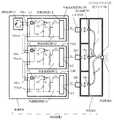
図1に示す照明装置1は、RGBの各色LED(発光ダイオード)2R、2G、2Bを発光させて任意の色温度の照明光を照射するもので、LED2R、2G、2Bを配した光源部3と、照明光の色温度及び明るさをコントロールする制御部4からなる。
【0016】
光源部3には、各色LED2R、2G、2Bが並設されると共に、各色の照射光を混合するバンドルファイバ5が配されている。
バンドルファイバ5は多数の光ファイバ6…が束ねられて形成され、その光入射端7R、7G、7BがLED2R、2G、2Bの数に応じて分岐形成され、その光出射端8で夫々の光ファイバがランダムに束ねられて形成されている。
【0017】
制御部4は、各色のLED2R、2G、2Bを接続した色温度設定回路10R、10G、10Bと、夫々の色温度設定回路10R、10G、10Bに対し、照明光の光量を可変調整する調光電圧VCを等しく供給する調光回路11を備えている。
一般に、LED2R、2G、2Bは、図2に示すように、定格が等しければ、駆動電流IR、IG、IBに比例した光量で点灯され、駆動電流−光量特性はいずれも等しいので、駆動電流IR、IG、IBを制御することにより個々のLED2R、2G、2Bごとに光量を調整することができる。
そこで、色温度設定回路10R、10G、10Bは、調光電圧VCに対して制御電圧VR、VG、VBを所定の比率に調整して出力する色温度設定器12と、制御電圧VR、VG、VBに応じた駆動電流IR、IG、IBを各LED2R、2G、2Bに対して出力する定電流回路13を備えており、制御電圧VR、VG、VBの比率を調整することにより、駆動電流IR、IG、IBを各LED2R、2G、2Bごとに調整できるようになっている。
【0018】
また、色温度設定回路10R、10G、10Bは、色温度設定器12に対し、外部から供給される調光電圧VCと、内部定電圧電源14の基準電圧V0を切り換えて供給するスイッチ15が設けられている。
色温度設定器12では、スイッチ15により切り換えて供給される調光電圧VCまたは基準電圧V0に対して、色温度設定器12の可変抵抗器等により制御電圧VR、VG、VBの比率を設定することができるようになっている。
【0019】
なお、色温度設定回路10R、10G、10Bには、調光電圧VCの入力端子16inと、入力された調光電圧VCをバッファ17を介して減衰させることなくそのまま出力する出力端子16outが形成され、いずれか一の色温度設定回路10R、10G、10Bの入力端子16inに調光回路11を接続し、あとは、色温度設定回路10R、10G、10Bの出力端子16outと入力端子16in同士を接続すれば、全ての色温度設定回路10R、10G、10Bに一定の調光電圧が供給される。
【0020】
以上が本発明の一構成例であって、次に作用を説明する。
各色LED2R,2G,2Bは、駆動電流−光量特性はいずれも等しく、駆動電流IR、IG、IBに比例した光量で発光される。
そこで、まず、夫々の色温度設定回路10R、10G、10Bのスイッチ15を内部定電圧電源14側に切り換えることにより、基準電圧V0に対して、色温度設定器12の可変抵抗器で制御電圧VR、VG、VBの比率を設定する。
【0021】
例えば、白色光で発光させる場合は、制御電圧/基準電圧=VR/V0=VG/V0=VB/V0=Cとなるように設定すれば、各定電流回路13から出力される駆動電流IR=IG=IBが等しくなる。したがって、各LED2R,2G,2BからRGBの三原色の光が同じ光量で照射され、バンドルファイバ5を通り、その光出射端8で混合され、白色光となって出射される。
その後、スイッチ15を調光回路11側に切り換えて、調光電圧VCを調整すれば、白色光のまま明るさを変えることができる。
【0022】
また、赤色の光量比を高くする場合は、色温度設定回路10R、10G、10Bにより、赤色の制御電圧/基準電圧=VR/V0が高くなるように設定すれば、色温度設定回路10Rの定電流回路13から出力される駆動電流IRが高くなる。したがって、LED2Rの光量が他のLED2G,2Bの光量に比して高くなり、バンドルファイバ5を通り、その光出射端8で混合され、赤色の光量比が高い光となって出射される。
その後、スイッチ15を調光回路11側に切り換えて、調光電圧VCを調整すれば、赤色の光量比を高く維持したまま、光の明るさを変えることができる。
【0023】
【発明の効果】
以上述べたように、本発明によれば、駆動電流に比例した光量で点灯されるRGBの各LEDに接続された色温度設定回路により、調光電圧に対する駆動電流の強さを設定することができ、調光回路により夫々の色温度設定回路に等しく供給される調光電圧を可変調整することができるので、色温度設定回路でRGBの各LEDの光量比を決定することにより、照明光の色温度を任意に設定することができ、その後、調光回路から供給する調光電圧を増減することにより照明光の色温度(光量比)を一定に維持したまま明るさを調整することができるという大変優れた効果を奏する。
【図面の簡単な説明】
【図1】本発明にかかる照明装置の概略構成を示す説明図。
【図2】LEDの駆動電流−光量特性を示すグラフ。
【図3】従来の照明装置を示す説明図。
【図4】LEDの電圧−光量特性を示すグラフ。
【符号の説明】
1………………………………照明装置
2R、2G、2B……………LED
3………………………………光源部
4………………………………制御部
5………………………………バンドルファイバ
6………………………………光ファイバ
7R、7G、7B……………光入射端
8………………………………光出射端
10R、10G、10B………色温度設定回路
11………………………………調光回路
12………………………………色温度設定器
13………………………………定電流回路
14………………………………内部定電圧電源
15………………………………スイッチ[0001]
BACKGROUND OF THE INVENTION
The present invention relates to an illuminating device that emits illumination light having an arbitrary color temperature by causing each color LED (light emitting diode) of RGB to be lit with a light amount proportional to a drive current.
[0002]
[Prior art]
In recent production lines, image processing technology is actively used to determine the type of workpiece that arrives when multiple types of workpieces are run simultaneously on the same line, and to inspect the quality of the workpiece. .
When performing image processing, the illumination device irradiates the workpiece with appropriate illumination light, and an image pickup device such as a CCD camera captures the image of the workpiece. However, the selection of illumination light is very important. Yes, it is necessary to set the optimum color and light amount according to the color and surface properties of the workpiece.
[0003]
For example, if a shiny workpiece such as a semiconductor wafer, LCD electrode, metal processing, surface mount solder pattern, blister pack, aluminum foil packaging, etc. is illuminated with white light, the reflected light will be transferred to the captured image. For this reason, the accuracy of image processing is lowered, and when a work covered with a heat-sensitive resin or an ultraviolet light curable resin is irradiated with illumination light including infrared light or ultraviolet light, it is exposed to light.
[0004]
In addition to the above-mentioned image processing field, there is a demand for an illumination device that can emit light of any color in store lighting and lighting design for show windows. For this reason, RGB three primary color LEDs are used. A lighting device has been proposed (see Non-Patent Document 1).
[0005]
[Non-Patent Document 1]
http://www.ccs-inc.co.jp/cgi-gin/hp.cgi?menu=102-111-02j
[0006]
This is because, as shown in FIG. 3, three sheets of the
[0007]
According to this, the light emitted from each of the
At this time, each of the
[0008]
[Problems to be solved by the invention]
However, in this case, after setting the color temperature of the light emitted from the
That is, as shown in FIG. 4, the LED generally has not only different voltage-light quantity characteristics for each color, but also the LEDs of the same color are not constant. Therefore, the voltage supplied to each LED is similarly changed. However, the color temperature cannot be kept constant.
For this reason, conventionally, it has been necessary to make individual adjustments while measuring the intensity of each wavelength component contained in the irradiation light using a spectrophotometer or the like, and the adjustment work is extremely troublesome. It was.
[0009]
Therefore, the present invention has a technical problem that, after setting the color temperature of illumination light, the brightness can be easily adjusted while maintaining the color temperature.
[0010]
[Means for Solving the Problems]
In order to solve this problem, the present invention is an illuminating device that emits illumination light of an arbitrary color temperature by emitting each color LED of RGB that is lit with a light amount proportional to a drive current, and connects each LED. And a dimming circuit that equally supplies a dimming voltage for variably adjusting the amount of illumination light to each of the color temperature setting circuits, the color temperature setting circuit corresponding to the dimming voltage A color temperature setting device that adjusts and outputs a control voltage to a predetermined ratio, and a constant current circuit that outputs a drive current corresponding to the control voltage to each LED, and a bundle that mixes the irradiation light of each LED The light incident end of the fiber is branched according to the number of LEDs, and each optical fiber is randomly bundled at the light emitting end.
[0011]
According to the present invention, the dimming voltage for variably adjusting the amount of illumination light is equally supplied from the dimming circuit to each color temperature setting circuit connected to each LED. That is, a dimming voltage having an equal voltage value is supplied to each color temperature setting and setting circuit. The dimming voltage input to each color temperature setting circuit is output as a control voltage adjusted to a voltage value of a predetermined ratio by the color temperature setting device, and a driving current corresponding to the control voltage is output from the constant current circuit to each LED. Is output for.
[0012]
In general, the light quantity of the LED is proportional to the drive current, and the drive current is determined by the control voltage input to the constant current circuit. Therefore, in the present invention, the light quantity of each LED can be controlled by the control voltage.
Since the control voltage is determined by the dimming voltage input to the color temperature setting device and the ratio set by the color temperature setting device, the ratio of the dimming voltage and control voltage can be set arbitrarily by the color temperature setting device. The light intensity ratio of each LED can be set, and if the dimming voltage is increased or decreased in this state, the overall brightness is controlled while maintaining the light intensity ratio of each LED constant.
[0013]
And, the bundle fiber that guides the irradiation light of each LED has its light incident end branched according to the number of LEDs, and each light fiber is randomly bundled at its light exit end. Light of each color incident from the end is guided to each optical fiber, and is uniformly mixed and emitted when emitted from the light exit end.
[0014]
DETAILED DESCRIPTION OF THE INVENTION
Hereinafter, embodiments of the present invention will be described in detail with reference to the drawings.
FIG. 1 is an explanatory diagram showing a schematic configuration of a lighting device according to the present invention, and FIG. 2 is a graph showing a drive current-light quantity characteristic of an LED.
[0015]
The illuminating device 1 shown in FIG. 1 emits illumination light of an arbitrary color temperature by causing each of RGB color LEDs (light emitting diodes) 2R, 2G, and 2B to emit light, and a light source unit 3 provided with
[0016]
The light source unit 3 includes
The bundle fiber 5 is formed by bundling a large number of
[0017]
The control unit 4 performs dimming to variably adjust the amount of illumination light for the color
In general,
Therefore, the color
[0018]
The color
In the color temperature setting device 12, the control voltages VR , VG , and VB are controlled by the variable resistor of the color temperature setting device 12 with respect to the dimming voltage VC or the reference voltage V0 supplied by being switched by the
[0019]
The color
[0020]
The above is one configuration example of the present invention, and the operation will be described next.
Each
Therefore, first, each of the color
[0021]
For example, in the case of emitting light with white light, if the control voltage / reference voltage = VR / V0 = VG / V0 = VB / V0 = C is set, the output from each constant
Thereafter, by switching the
[0022]
When the light quantity ratio of red is increased, the color temperature setting circuit 10R can be set by increasing the red control voltage / reference voltage = VR / V0 by the color
Thereafter, by switching the
[0023]
【The invention's effect】
As described above, according to the present invention, the strength of the drive current with respect to the dimming voltage can be set by the color temperature setting circuit connected to each of the RGB LEDs that are lit with a light amount proportional to the drive current. The dimming circuit can variably adjust the dimming voltage that is equally supplied to each color temperature setting circuit. Therefore, by determining the light quantity ratio of each LED of RGB by the color temperature setting circuit, The color temperature can be set arbitrarily, and then the brightness can be adjusted while maintaining the color temperature (light quantity ratio) of the illumination light constant by increasing or decreasing the dimming voltage supplied from the dimming circuit. It has a very excellent effect.
[Brief description of the drawings]
FIG. 1 is an explanatory diagram showing a schematic configuration of a lighting device according to the present invention.
FIG. 2 is a graph showing a drive current-light quantity characteristic of an LED.
FIG. 3 is an explanatory view showing a conventional lighting device.
FIG. 4 is a graph showing a voltage-light quantity characteristic of an LED.
[Explanation of symbols]
1 ………………………………
3 ……………………………… Light Source 4 ……………………………… Control Unit 5 ………………………………
Claims (2)
Translated fromJapanese駆動電流に比例した光量で点灯される各色LEDを接続した色温度設定回路と、夫々の色温度設定回路に対し、照明光の光量を可変調整する調光電圧を等しく供給する調光回路を備え、
前記色温度設定回路は、前記調光電圧に対して制御電圧を所定の比率に調整して出力する色温度設定器と、制御電圧に応じた駆動電流を各LEDに対して出力する定電流回路を備え、
前記各LEDの照射光を混合するバンドルファイバの光入射端がLEDの数に応じて分岐形成され、その光出射端で夫々の光ファイバがランダムに束ねられていることを特徴とする照明装置。An illumination device that emits illumination light of an arbitrary color temperature by causing each color LED of RGB to emit light,
A color temperature setting circuit that connects each color LED that is lit with a light amount proportional to the drive current, and a dimming circuit that equally supplies a dimming voltage that variably adjusts the amount of illumination light to each color temperature setting circuit ,
The color temperature setting circuit includes a color temperature setting device that outputs a control voltage adjusted to a predetermined ratio with respect to the dimming voltage, and a constant current circuit that outputs a driving current corresponding to the control voltage to each LED. With
An illumination device, wherein light incident ends of bundle fibers for mixing irradiation light of the LEDs are branched according to the number of LEDs, and the respective optical fibers are randomly bundled at the light emitting ends.
駆動電流に比例した光量で点灯される各色LEDを接続した色温度設定回路と、夫々の色温度設定回路に対し、照明光の光量を可変調整する調光電圧を等しく供給する調光回路を備え、
前記色温度設定回路は、前記調光電圧に対して制御電圧を所定の比率に調整して出力する色温度設定器と、制御電圧に応じた駆動電流を各LEDに対して出力する定電流回路を備えたことを特徴とする照明装置。An illumination device that emits illumination light of an arbitrary color temperature by causing each color LED of RGB to emit light,
A color temperature setting circuit that connects each color LED that is lit with a light amount proportional to the drive current, and a dimming circuit that equally supplies a dimming voltage that variably adjusts the amount of illumination light to each color temperature setting circuit ,
The color temperature setting circuit includes a color temperature setting device that outputs a control voltage adjusted to a predetermined ratio with respect to the dimming voltage, and a constant current circuit that outputs a driving current corresponding to the control voltage to each LED. An illumination device comprising:
Priority Applications (4)
| Application Number | Priority Date | Filing Date | Title |
|---|---|---|---|
| JP2003163211AJP4167131B2 (en) | 2003-06-09 | 2003-06-09 | Lighting device |
| KR1020040041221AKR101024853B1 (en) | 2003-06-09 | 2004-06-07 | Lighting device |
| US10/862,377US7144130B2 (en) | 2003-06-09 | 2004-06-08 | Illumination device |
| CNB200410059227XACN100518425C (en) | 2003-06-09 | 2004-06-09 | lighting device |
Applications Claiming Priority (1)
| Application Number | Priority Date | Filing Date | Title |
|---|---|---|---|
| JP2003163211AJP4167131B2 (en) | 2003-06-09 | 2003-06-09 | Lighting device |
Publications (2)
| Publication Number | Publication Date |
|---|---|
| JP2004363061A JP2004363061A (en) | 2004-12-24 |
| JP4167131B2true JP4167131B2 (en) | 2008-10-15 |
Family
ID=33487571
Family Applications (1)
| Application Number | Title | Priority Date | Filing Date |
|---|---|---|---|
| JP2003163211AExpired - Fee RelatedJP4167131B2 (en) | 2003-06-09 | 2003-06-09 | Lighting device |
Country Status (4)
| Country | Link |
|---|---|
| US (1) | US7144130B2 (en) |
| JP (1) | JP4167131B2 (en) |
| KR (1) | KR101024853B1 (en) |
| CN (1) | CN100518425C (en) |
Families Citing this family (36)
| Publication number | Priority date | Publication date | Assignee | Title |
|---|---|---|---|---|
| US20060023271A1 (en)* | 2004-07-30 | 2006-02-02 | Boay Yoke P | Scanner with color profile matching mechanism |
| US20060098451A1 (en)* | 2004-11-08 | 2006-05-11 | Global Fiberoptics Inc. | Illuminator for video display apparatus |
| JP2006303016A (en)* | 2005-04-18 | 2006-11-02 | Rohm Co Ltd | LIGHTING DEVICE AND DISPLAY DEVICE USING THE SAME |
| WO2007003006A1 (en)* | 2005-07-05 | 2007-01-11 | Winovate Pty Ltd | A multicolour led lighting circuit |
| US20070171638A1 (en)* | 2006-01-24 | 2007-07-26 | Sbc Knowledge Ventures, L.P. | Apparatus and methods for transmitting light over optical fibers |
| KR20070077719A (en)* | 2006-01-24 | 2007-07-27 | 삼성전기주식회사 | Driving device of color LED |
| US8084948B2 (en)* | 2006-04-11 | 2011-12-27 | Koninklijke Philips Electronics N.V. | Method for dimming a light generatng system for generating light with a variable color |
| JP5535628B2 (en)* | 2006-08-14 | 2014-07-02 | コーニンクレッカ フィリップス エヌ ヴェ | Electroluminescent device with variable color point |
| US7288902B1 (en)* | 2007-03-12 | 2007-10-30 | Cirrus Logic, Inc. | Color variations in a dimmable lighting device with stable color temperature light sources |
| CN201045454Y (en)* | 2007-04-24 | 2008-04-09 | 鹤山丽得电子实业有限公司 | LED lamp capable of adjusting colour temperature |
| JP5141874B2 (en)* | 2007-06-28 | 2013-02-13 | 東芝ライテック株式会社 | Lighting device |
| KR100953169B1 (en)* | 2007-10-24 | 2010-04-20 | 한국광기술원 | Color temperature control method using multi-color light emitting diode and recording medium recording program thereof |
| US8716952B2 (en) | 2009-08-04 | 2014-05-06 | Cree, Inc. | Lighting device having first, second and third groups of solid state light emitters, and lighting arrangement |
| EP2320125A1 (en)* | 2009-11-04 | 2011-05-11 | Koninklijke Philips Electronics N.V. | Lighting device |
| KR101107561B1 (en)* | 2009-11-12 | 2012-01-31 | (주)화이버 옵틱코리아 | Fiber optic integrated LED lighting device |
| US20110115407A1 (en)* | 2009-11-13 | 2011-05-19 | Polar Semiconductor, Inc. | Simplified control of color temperature for general purpose lighting |
| JP5807195B2 (en) | 2010-04-08 | 2015-11-10 | パナソニックIpマネジメント株式会社 | Light emitting device |
| CN102679191A (en)* | 2011-03-11 | 2012-09-19 | 深圳市钧多立实业有限公司 | Intelligent light source with adjustable color temperature |
| US20130088152A1 (en)* | 2011-03-31 | 2013-04-11 | B-K Lighting, Inc. | Dimming apparatus for solid state lighting fixtures |
| JP2013069501A (en)* | 2011-09-21 | 2013-04-18 | Panasonic Corp | Lighting device and illuminating device using the same |
| JP6217957B2 (en)* | 2011-09-29 | 2017-10-25 | 東芝ライテック株式会社 | Lighting device |
| US20130081610A1 (en)* | 2011-09-29 | 2013-04-04 | Osram Opto Semiconductors Gmbh | Oven Lighting |
| US8698980B2 (en) | 2011-11-14 | 2014-04-15 | Planck Co., Ltd. | Color regulating device for illumination and apparatus using the same, and method of regulating color |
| JP5518126B2 (en)* | 2012-04-27 | 2014-06-11 | シャープ株式会社 | Lighting device |
| JP2014060086A (en) | 2012-09-19 | 2014-04-03 | Beat Sonic:Kk | Led lamp |
| JP5460839B2 (en)* | 2012-12-12 | 2014-04-02 | 京セラドキュメントソリューションズ株式会社 | Image forming apparatus |
| CN103906309B (en)* | 2012-12-27 | 2016-07-06 | 财团法人工业技术研究院 | Light source device and lighting device |
| US9693408B2 (en) | 2012-12-28 | 2017-06-27 | Industrial Technology Research Institute | Light source apparatus |
| US10039169B2 (en) | 2012-12-28 | 2018-07-31 | Industrial Technology Research Institute | Light source apparatus |
| US10485070B2 (en) | 2012-12-28 | 2019-11-19 | Industrial Technology Research Institute | Light source apparatus and display apparatus |
| JP5670528B2 (en)* | 2013-09-09 | 2015-02-18 | 三菱電機株式会社 | Lighting device and lighting apparatus |
| CN104994619A (en)* | 2015-06-10 | 2015-10-21 | 晶正照明科技有限公司 | LED driving circuit with high light effect |
| CN106801798A (en)* | 2017-03-24 | 2017-06-06 | 重庆市光利医疗科技有限公司 | A kind of optical fiber lamp of adjustable color |
| CN109377939B (en)* | 2018-11-16 | 2023-10-13 | 上海得倍电子技术有限公司 | High-efficiency LED driving device |
| CN110536511B (en)* | 2019-09-02 | 2021-06-11 | 鹰潭阳光照明有限公司 | Dimmable LED lamp circuit |
| CN112383688B (en)* | 2020-11-10 | 2023-03-24 | 珠海格力电器股份有限公司 | Camera shooting light supplement method and device, electronic equipment and intelligent terminal |
Family Cites Families (18)
| Publication number | Priority date | Publication date | Assignee | Title |
|---|---|---|---|---|
| DE2813262A1 (en)* | 1977-03-29 | 1978-10-05 | Canon Kk | TELEVISION CAMERA |
| JPH05193400A (en)* | 1992-01-22 | 1993-08-03 | Asahi Glass Co Ltd | Head up display |
| JP2602932Y2 (en)* | 1993-12-03 | 2000-02-07 | 旭光学工業株式会社 | LED drive circuit |
| JPH08250771A (en) | 1995-03-08 | 1996-09-27 | Hiyoshi Denshi Kk | Light emitting color variable LED device and LED light emitting color control device |
| US20040052076A1 (en)* | 1997-08-26 | 2004-03-18 | Mueller George G. | Controlled lighting methods and apparatus |
| JP4286935B2 (en)* | 1998-10-14 | 2009-07-01 | 株式会社朝日ラバー | Toning lighting device |
| JP2001135857A (en) | 1999-11-08 | 2001-05-18 | Rabo Sufia Kk | Color display device |
| JP4044261B2 (en) | 2000-03-10 | 2008-02-06 | 株式会社東芝 | Semiconductor light emitting device and manufacturing method thereof |
| JP2001257397A (en) | 2000-03-13 | 2001-09-21 | Toyama Prefecture | Phase-controlled multi-electrode type ac discharge excitation laser device |
| US6394626B1 (en)* | 2000-04-11 | 2002-05-28 | Lumileds Lighting, U.S., Llc | Flexible light track for signage |
| US6636003B2 (en)* | 2000-09-06 | 2003-10-21 | Spectrum Kinetics | Apparatus and method for adjusting the color temperature of white semiconduct or light emitters |
| JP2002246651A (en) | 2001-02-20 | 2002-08-30 | Hitachi Cable Ltd | Light emitting diode and method of manufacturing the same |
| JP2002238846A (en) | 2001-02-21 | 2002-08-27 | Asahi Optical Co Ltd | Light source device for endoscope |
| JP2002329587A (en)* | 2001-05-01 | 2002-11-15 | Toyoda Gosei Co Ltd | Led lamp |
| JP2003060223A (en) | 2001-08-20 | 2003-02-28 | Osaka Gas Co Ltd | Flame sensor |
| US6921920B2 (en)* | 2001-08-31 | 2005-07-26 | Smith & Nephew, Inc. | Solid-state light source |
| CN2502636Y (en)* | 2001-09-25 | 2002-07-31 | 黄文平 | Electronic vaginoscope |
| FI115948B (en)* | 2003-06-06 | 2005-08-15 | Teknoware Oy | Adjusting the color temperature of the luminaire |
- 2003
- 2003-06-09JPJP2003163211Apatent/JP4167131B2/ennot_activeExpired - Fee Related
- 2004
- 2004-06-07KRKR1020040041221Apatent/KR101024853B1/ennot_activeExpired - Fee Related
- 2004-06-08USUS10/862,377patent/US7144130B2/ennot_activeExpired - Fee Related
- 2004-06-09CNCNB200410059227XApatent/CN100518425C/ennot_activeExpired - Fee Related
Also Published As
| Publication number | Publication date |
|---|---|
| KR20040105596A (en) | 2004-12-16 |
| US20040246742A1 (en) | 2004-12-09 |
| US7144130B2 (en) | 2006-12-05 |
| KR101024853B1 (en) | 2011-03-31 |
| CN1575081A (en) | 2005-02-02 |
| CN100518425C (en) | 2009-07-22 |
| JP2004363061A (en) | 2004-12-24 |
Similar Documents
| Publication | Publication Date | Title |
|---|---|---|
| JP4167131B2 (en) | Lighting device | |
| KR100805396B1 (en) | LED array driving method, linearly changing color temperature of white light and lighting fixture | |
| KR101503092B1 (en) | How to define color gamut in solid-state lighting panels | |
| JP5243531B2 (en) | System and method for calibrating a solid state lighting panel using combined light output measurement results | |
| JP5620332B2 (en) | System and method for calibrating a solid state lighting panel | |
| US6753661B2 (en) | LED-based white-light backlighting for electronic displays | |
| Narendran et al. | Characterizing LEDs for general illumination applications: mixed-color and phosphor-based white sources | |
| CN101513123A (en) | Generating light by color mixing | |
| JP2005259699A (en) | System for generating white light using LED and its operating method | |
| CN103270367B (en) | The method controlling there is the luminaire of many array of source | |
| US20170208236A1 (en) | Image pickup system | |
| TWI454179B (en) | A white light emitting device for an image reading device, and a linear lighting device using the same | |
| JP4511634B1 (en) | White light emitting device in image reading device and line illumination device using the same | |
| JP4474491B1 (en) | White light emitting device and line illumination device using the same | |
| JP5037694B2 (en) | Illumination device and liquid crystal display device including the same | |
| US11991805B2 (en) | Control of dynamic brightness of light-emitting diode array | |
| JP2011114306A (en) | Led drive circuit, and lighting apparatus | |
| HK1072870A (en) | Illumination apparatus | |
| JP4715244B2 (en) | Projection device | |
| KR20070078314A (en) | White balance maintaining device of light emitting diode and method | |
| JP2007080532A (en) | LED lighting device | |
| TWI288379B (en) | Chrominance control circuit of multi-color light source backlight module and light detection element thereof | |
| KR20160136663A (en) | Improved lighting device and method for controlling the same |
Legal Events
| Date | Code | Title | Description |
|---|---|---|---|
| A621 | Written request for application examination | Free format text:JAPANESE INTERMEDIATE CODE: A621 Effective date:20050404 | |
| A977 | Report on retrieval | Free format text:JAPANESE INTERMEDIATE CODE: A971007 Effective date:20080215 | |
| A131 | Notification of reasons for refusal | Free format text:JAPANESE INTERMEDIATE CODE: A131 Effective date:20080219 | |
| A521 | Request for written amendment filed | Free format text:JAPANESE INTERMEDIATE CODE: A523 Effective date:20080421 | |
| TRDD | Decision of grant or rejection written | ||
| A01 | Written decision to grant a patent or to grant a registration (utility model) | Free format text:JAPANESE INTERMEDIATE CODE: A01 Effective date:20080715 | |
| A01 | Written decision to grant a patent or to grant a registration (utility model) | Free format text:JAPANESE INTERMEDIATE CODE: A01 | |
| A61 | First payment of annual fees (during grant procedure) | Free format text:JAPANESE INTERMEDIATE CODE: A61 Effective date:20080731 | |
| R150 | Certificate of patent or registration of utility model | Free format text:JAPANESE INTERMEDIATE CODE: R150 | |
| FPAY | Renewal fee payment (event date is renewal date of database) | Free format text:PAYMENT UNTIL: 20110808 Year of fee payment:3 | |
| FPAY | Renewal fee payment (event date is renewal date of database) | Free format text:PAYMENT UNTIL: 20110808 Year of fee payment:3 | |
| S531 | Written request for registration of change of domicile | Free format text:JAPANESE INTERMEDIATE CODE: R313531 | |
| FPAY | Renewal fee payment (event date is renewal date of database) | Free format text:PAYMENT UNTIL: 20110808 Year of fee payment:3 | |
| R350 | Written notification of registration of transfer | Free format text:JAPANESE INTERMEDIATE CODE: R350 | |
| FPAY | Renewal fee payment (event date is renewal date of database) | Free format text:PAYMENT UNTIL: 20120808 Year of fee payment:4 | |
| FPAY | Renewal fee payment (event date is renewal date of database) | Free format text:PAYMENT UNTIL: 20130808 Year of fee payment:5 | |
| S531 | Written request for registration of change of domicile | Free format text:JAPANESE INTERMEDIATE CODE: R313531 | |
| S533 | Written request for registration of change of name | Free format text:JAPANESE INTERMEDIATE CODE: R313533 | |
| R350 | Written notification of registration of transfer | Free format text:JAPANESE INTERMEDIATE CODE: R350 | |
| R250 | Receipt of annual fees | Free format text:JAPANESE INTERMEDIATE CODE: R250 | |
| R250 | Receipt of annual fees | Free format text:JAPANESE INTERMEDIATE CODE: R250 | |
| S533 | Written request for registration of change of name | Free format text:JAPANESE INTERMEDIATE CODE: R313533 | |
| R350 | Written notification of registration of transfer | Free format text:JAPANESE INTERMEDIATE CODE: R350 | |
| R250 | Receipt of annual fees | Free format text:JAPANESE INTERMEDIATE CODE: R250 | |
| LAPS | Cancellation because of no payment of annual fees |