JP4166428B2 - Apparatus and method for repairing furnace wall in coke oven carbonization chamber - Google Patents
Apparatus and method for repairing furnace wall in coke oven carbonization chamberDownload PDFInfo
- Publication number
- JP4166428B2 JP4166428B2JP2000291983AJP2000291983AJP4166428B2JP 4166428 B2JP4166428 B2JP 4166428B2JP 2000291983 AJP2000291983 AJP 2000291983AJP 2000291983 AJP2000291983 AJP 2000291983AJP 4166428 B2JP4166428 B2JP 4166428B2
- Authority
- JP
- Japan
- Prior art keywords
- furnace wall
- carbonization chamber
- coke oven
- oven carbonization
- repair device
- Prior art date
- Legal status (The legal status is an assumption and is not a legal conclusion. Google has not performed a legal analysis and makes no representation as to the accuracy of the status listed.)
- Expired - Fee Related
Links
Images


Landscapes
- Coke Industry (AREA)
Description
Translated fromJapanese【0001】
【発明の属する技術分野】
本発明は、コークス炉炭化室の炉壁補修を行うにあたり、炭化室内に挿入し、内部に作業者が入って炉壁の補修を行うコークス炉炭化室の炉壁補修装置および方法に関する。
【0002】
【従来の技術】
従来、コークス炉炭化室の炉壁補修は、コークス炉の操業を停止して行うか、炭化室上部の装炭口からキャスタブル注入パイプを挿入して補修部を溶射することによって行われてきた。
しかしながら、コークス炉の操業を停止することは熱量損失が大きいのみならず、準備作業および操業再開作業が煩雑であり、又、キャスタブルを溶射することは簡単な補修には対応できるものの、炉壁の大きな欠損を完全に補修するには問題があった。
【0003】
そのため、例えば、特開平8-81681 号公報では、コークス炉炭化室の炉壁補修装置として熱間補修工事用断熱ボックスの一例が開示されている。そして、その断熱ボックスを炭化室内に挿入し、挿入した断熱ボックス内に作業者が入って補修を行うことで、熱間状態での補修を行えるとしている。
ここで、特開平8-81681 号公報に開示された熱間補修工事用断熱ボックスは、コークス炉の炭化室両側の炉壁崩壊穴(つまり、補修部)の大きさより大きい面積の側面と両側の炉壁間隔より狭い幅の底面と天井面とを構設する枠組の主骨として冷却水管をユーターン状に往復迂回して形設し、同枠組に断熱ボードを着脱自在に貼設して筐体状となしたものである。
【0004】
【発明が解決しようとする課題】
しかしながら、コークス炉の炭化室の炉壁幅は、通常400mm 程度と非常に狭いものであり、内部に作業者を収納し、かつ、十分に断熱を行うようにするためには、炉壁補修装置の外幅を炭化室の炉壁幅ぎりぎりとするが最低限の条件として必要となる。
【0005】
一方、コークス炉の炭化室の炉壁は、コークスの生産に伴って凹凸が生じており、平坦ではない。また、壁面には、各種付着物も形成されている。
そのため、炉壁補修装置を炉壁幅ぎりぎりの幅とすると、炉壁補修装置が炉壁にひっかかり、炭化室内に炉壁補修装置をスムーズに挿入することができないという問題があった。
【0006】
本発明は、炉壁補修装置を炭化室内にスムーズに挿入することを可能とし、かつ、内部に入る作業者の作業スペースを十分に確保することが可能な炉壁補修装置及び方法を適用することを目的とする。
【0007】
【課題を解決するための手段】
本発明は、コークス炉炭化室内に挿入し、内部に作業者が入って炉壁の補修を行うコークス炉炭化室の炉壁補修装置であって、床部と、該床部の両側に直立し、取り外し可能な断熱パネルをパネル枠材にはめ込んで構成した一対の側壁部と、該一対の側壁部の上端を橋架し、逆U字形状として、たわませることで拡縮可能とした天井材と、前記一対の側壁部の上側位置に渡設し、前記側壁間を拡幅する拡縮部材と、エアを循環させて炉壁補修装置の内部の冷却を行うクーラダクトと、から構成することを特徴とするコークス炉炭化室の炉壁補修装置によって上記課題を解決した。
【0008】
ここで、前記拡縮部材としてはターンバックルを好適とする。
また、本発明は、上記いずれかの炉壁補修装置を用いるコークス炉炭化室の炉壁補修方法であって、前記炉壁補修装置をコークス炉炭化室内に挿入する第1の工程と、前記一対の側壁部の上側を、拡縮部材で拡幅する第2の工程と、拡幅した内部に作業者が入る第3の工程と、コークス炉炭化室炉壁の補修箇所に対応する位置の断熱パネルを取り外す第4の工程と、炉壁の補修を行う第5の工程と、からなることを特徴とするコークス炉炭化室の炉壁補修方法によって上記課題を解決したのである。
【0009】
なお、必要に応じ、前記第2の工程と第3の工程を繰り返し、作業者が炉壁補修装置の奥に入っていくようにすることを好適とする。
【0010】
【発明の実施の形態】
本発明の好適な実施の形態を、図1に基づき説明する。
本発明の炉壁補修装置3は、床部6と、その床部6の両側に直立し、取り外し可能な断熱パネル4aをパネル枠材4bにはめ込むことで構成された一対の側壁部4と、その一対の側壁部4の上端を橋架し、拡縮可能とした天井材5から構成される。なお、本発明の炉壁補修装置3を載荷する架台20については後述する。
【0011】
炉壁補修装置3内には、作業者が入ることから、内部温度を一定温度(例えば、50℃程度)以下とすることが必要である。そのため、クーラダクト8を設けておき、エア10を循環させて炉壁補修装置3の内部の冷却を行う。
断熱パネル4aは、パネル枠材4bにはめ込まれており、炉壁補修装置3の側壁部4を構成する。断熱パネル4aの内表面は、例えば薄鋼板14a とされており、その外面側に断熱材14b が貼付された構造となっている。断熱材14b としては、例えば耐火断熱繊維であるカオウール(商品名、イソライト工業(株)製)等を好適に適用することができる。
【0012】
この断熱パネル4aは、所要の箇所を自在に取り外すことが可能とされており、図1に示すように、作業者が、補修箇所19に相当する位置の断熱パネルを外して、必要な補修を行うのである。
次に、側壁部4の上部を押し広げ、作業者が自由に内部に入れるようにするための拡縮部材7について説明する。
【0013】
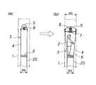
本発明では、図2(a)に示すように炉壁補修装置3の幅をコークス炉炭化室1の炉壁幅よりも狭くなるようにしておくことを特徴とする。こうすることで、炉壁補修装置3をコークス炉炭化室1に挿入する際に、装置が炉壁にひっかかるトラブルを解消することができる。
しかし、そのままでは炉壁補修装置3の幅を充分に確保することができないため、作業者が装置内に自由に入ることができない。
【0014】
そのため、図2(b)に示すように、拡縮部材7を用いて炉壁補修装置3の上部側の幅を広げるようにする。こうすることで、装置内に入るために必要となる一定の幅を確保することができる。すなわち、人(作業者)は、足下に比べ、体躯部と頭部の幅をより必要とすることから、装置内に入る際、装置の上部を押し広げるようにするのである。ここで、拡縮部材7としては、図4に示すようなターンバックルを好適とする。このターンバックルは、締付部7aの正逆回転に対応して、ねじ部7bを拡縮させる構造となっている。
【0015】
ただし、拡縮部材7をターンバックルに限定するものではなく、油圧ジャッキ、油圧シリンダ等を用いてもよい。また、動作機構は、油圧に限定されず、空気圧であってもよく、また、機械式であってもよいことは言うまでもない。
また、拡縮部材7は、取り外し式のものを必要に応じて取り付け、拡幅させながら内部に入っていくようにしてもよいし、また、所要に位置にあらかじめ取り付けておいてもよい。拡縮部材7の拡幅は、作業者が必要に応じてひとつずつ行うようにしてもよいし、また、自動化を行って遠隔操作で一斉に行うようにしてもよい。
【0016】
次に、天井材5について説明する。
本実施の形態では、図1に示すように炉壁補修装置3の天井材5を逆U字形状とし、天井材をたわませることで拡縮を可能としている。
【0017】
次に、図3に基づき、架台20について説明する。
コークス炉炭化室1は、幅が狭く、かつ、高さの高い炉であり、奥行きも非常に深い。
一方、本発明の炉壁補修装置3は、天井部を拡縮自在とすることから、あまり高剛性のものとすることはできない。しかしながら、最低でもクレーン吊り等の運搬を可能とすることが必要である。そのため、炉壁補修装置3そのものはできるだけコンパクトにして軽量とする必要がある。一方、コークス炉炭化室の高さは6m前後であり、炉壁の補修箇所は高さ5m前後の上部側に特に多い傾向にある。
【0018】
そのため、本発明の炉壁補修装置3は作業者が入る程度の高さとしてコンパクトにしておき、別に架台20を設けるようにする。
架台20は、あらかじめ角パイプ等の架台枠材21で所要の高さに組み立てておく。架台20の高さは、炉壁の補修箇所の高さに合わせて適宜決定すればよい。
次に、本発明のコークス炉炭化室の炉壁補修方法について説明する。
【0019】
まず、コークス炉炭化室1にローラチャンネル23を挿入して、炭化室底面に敷設し、ローラ22を配置する。そのローラ22の上に架台20をのせて、炉内に挿入する。なお、このローラ22に替えて架台20に車輪をつける方式としてもよいことは言うまでもない。ここで、この架台20の幅は、炉壁補修装置3の床部6の幅に等しくすることを好適とする。
【0020】
次に、クレーン、レッカー車等を用いて、炉壁補修装置3を架台20上に載荷する。
炉壁補修装置3には車輪11を設けておき、架台20上を滑らせて炉内への挿入を行う。炉内への挿入には、作業者が手で押し込んでもよいし、また、チェーンブロック等を用いてもよい。ここで、炉壁補修装置3の幅を炉内幅よりも狭くしていることから、挿入時に炉壁にひっかかるトラブルをすべて解消することができるのである。
【0021】
炉壁補修装置3を炉内に挿入したら、クーラダクト8にエア10を送給し、炉壁補修装置3内部の冷却を行う。
作業者が炉壁補修装置3の内部に入る際は、すでに図2において説明したように、拡縮部材7を用いて炉壁補修装置3の上部側の幅を拡幅する。
そして、別の手段であらかじめ調査しておいた補修箇所に該当する断熱パネルを外し、炉壁補修を行う。
【0022】
補修完了後は、拡縮部材7を縮幅して必要に応じ取り外しながら退出し、もしくは、退出後に拡縮部材7を一斉に縮幅し、エア10の送給を止めた後、炉壁補修装置3を炉外に引き出してクレーン、レッカー車等で吊り出す。最後に、架台20を引き出し、ローラ22とローラチャネル23を撤去して作業を完了する。
【0023】
【発明の効果】
本発明によって、炉壁補修装置が炉内への挿入時に炉壁にひっかかると言うトラブルを解消することができ、かつ、内部に入る作業者の作業スペースを十分に確保することができるようになった。
その結果、炉壁補修の作業効率を大幅に向上させることができた。
【図面の簡単な説明】
【図1】本発明の炉壁補修装置の断面図(a)とA−A視図(b)である。
【図2】炉壁補修装置の壁面パネル部の拡縮を説明する模式図である。
【図3】コークス炉炭化室に装着した炉壁補修装置を示す側面断面図である。
【図4】ターンバックルの斜視図である。
【符号の説明】
1 コークス炉炭化室
2 作業者
3 炉壁補修装置(ボックス)
4 側壁部
4a 断熱パネル
4b パネル枠材
4c 薄鋼板
4d 断熱材
5 天井材
6 床材
7 拡縮部材(ターンバックル)
7a 締付部
7b ねじ部
8 クーラダクト
9 装炭口
10 エア
11 車輪
14a 薄鋼板
14b 断熱材
18 耐火れんが
19 補修部(れんが欠落部)
20 架台
21 架台枠材(角パイプ)
22 ローラ
23 ローラチャンネル[0001]
BACKGROUND OF THE INVENTION
The present invention relates to a furnace wall repairing apparatus and method for a coke oven carbonization chamber that is inserted into a carbonization chamber and an operator enters to repair the furnace wall when repairing the furnace wall of the coke oven carbonization chamber.
[0002]
[Prior art]
Conventionally, furnace wall repair in a coke oven carbonization chamber has been performed by stopping operation of the coke oven or by spraying a repairable portion by inserting a castable injection pipe from a coal inlet at the top of the carbonization chamber.
However, stopping the operation of the coke oven not only causes a large loss of heat, but the preparation work and the restarting operation are complicated, and spraying the castable can cope with simple repairs, but There was a problem in completely repairing a large defect.
[0003]
Therefore, for example, JP-A-8-81681 discloses an example of a heat insulation box for hot repair work as a furnace wall repair device for a coke oven carbonization chamber. Then, the heat insulation box is inserted into the carbonization chamber, and an operator enters the inserted heat insulation box to perform repairs.
Here, the heat insulation box for hot repair disclosed in Japanese Patent Application Laid-Open No. 8-81681 has a side wall with a larger area than the size of the furnace wall collapse hole (that is, the repair part) on both sides of the coking chamber of the coke oven. A cooling water pipe is reciprocated in a U-turn shape as the main frame of a frame that forms a bottom surface and ceiling surface with a width narrower than the furnace wall interval, and a heat insulation board is detachably attached to the frame. It has become a shape.
[0004]
[Problems to be solved by the invention]
However, the width of the coke oven's carbonization chamber is usually very narrow, about 400mm, and in order to accommodate workers inside and provide sufficient insulation, a furnace wall repair device is required. Although the outer width of the steel is almost the furnace wall width of the carbonization chamber, it is necessary as a minimum condition.
[0005]
On the other hand, the furnace wall of the coking oven carbonization chamber is uneven due to coke production and is not flat. Various deposits are also formed on the wall surface.
For this reason, if the furnace wall repair device has a width that is almost the width of the furnace wall, the furnace wall repair device is caught on the furnace wall, and the furnace wall repair device cannot be smoothly inserted into the carbonization chamber.
[0006]
The present invention is to apply a furnace wall repairing apparatus and method capable of smoothly inserting a furnace wall repairing apparatus into a carbonization chamber and sufficiently securing a working space for workers entering the inside. With the goal.
[0007]
[Means for Solving the Problems]
The present invention relates to a furnace wall repair device for a coke oven carbonization chamber that is inserted into a coke oven carbonization chamber and an operator enters inside to repair the furnace wall, and is provided upright on the floor and both sides of the floor. A pair of side wall parts configured by fitting a removable heat insulation panel into a panel frame material, and a ceiling material that bridges the upper ends of the pair of side wall partsand is bent into aninverted U shape to allow expansion and contraction. Andan expansion / contraction member that extends over the pair of side wall portions and widens between the side walls, and a cooler duct that circulates air and cools the inside of the furnace wall repair device. The above problems were solved by the furnace wall repair device in the coke oven carbonization chamber.
[0008]
Here, thepre-Symbol scaling member preferably made of a turnbuckle.
The present invention also relates to a method for repairing a coke oven carbonization chamber using any one of the above-described furnace wall repair devices, the first step of inserting the furnace wall repair device into a coke oven carbonization chamber, and the pair The second step of widening the upper side of the side wall portion of the steel sheet with the expansion / contraction member, the third step of entering the worker into the widened interior, and removing the heat insulation panel at the position corresponding to the repaired portion of the coke oven carbonization chamber furnace wall The above-mentioned problem has been solved by a furnace wall repairing method for a coke oven carbonization chamber characterized by comprising a fourth process and a fifth process for repairing the furnace wall.
[0009]
In addition, it is preferable that the second step and the third step are repeated as necessary so that an operator enters the furnace wall repair device.
[0010]
DETAILED DESCRIPTION OF THE INVENTION
A preferred embodiment of the present invention will be described with reference to FIG.
The furnace
[0011]
Since an operator enters the furnace
The
[0012]
The
Next, the expansion /
[0013]
The present invention is characterized in that the width of the furnace
However, since the width of the furnace
[0014]
Therefore, as shown in FIG.2 (b), the width | variety of the upper part side of the furnace
[0015]
However, the expansion /
Further, the expansion /
[0016]
Next, the
In this embodiment, the
[0017]
Next, the
The coke
On the other hand, the furnace
[0018]
Therefore, the furnace
The
Next, the furnace wall repair method of the coke oven carbonization chamber of the present invention will be described.
[0019]
First, the
[0020]
Next, the furnace
The furnace
[0021]
When the furnace
When the worker enters the inside of the furnace
And the heat insulation panel applicable to the repair location investigated beforehand by another means is removed, and a furnace wall repair is performed.
[0022]
After completion of the repair, the expansion /
[0023]
【The invention's effect】
According to the present invention, it is possible to eliminate the trouble that the furnace wall repair device gets caught in the furnace wall when inserted into the furnace, and it is possible to secure a sufficient working space for the worker entering the inside. It was.
As a result, the work efficiency of furnace wall repair could be greatly improved.
[Brief description of the drawings]
FIG. 1 is a cross-sectional view (a) and a view taken along line AA of a furnace wall repair device of the present invention (b).
FIG. 2 is a schematic diagram for explaining expansion / contraction of a wall surface panel portion of a furnace wall repair device.
FIG. 3 is a side sectional view showing a furnace wall repairing device installed in a coke oven carbonization chamber.
FIG. 4 is a perspective view of a turnbuckle.
[Explanation of symbols]
1 Coke
4 Side wall
4a Thermal insulation panel
4b Panel frame material
4c sheet steel
4d
7a Tightening part
10 Air
11 wheels
14a sheet steel
14b insulation
18 Refractory brick
19 Repair Department (Brick missing part)
20 frame
21 Mounting frame material (square pipe)
22 Laura
23 Roller channel
Claims (4)
Translated fromJapanese床部と、
該床部の両側に直立し、取り外し可能な断熱パネルをパネル枠材にはめ込んで構成した一対の側壁部と、
該一対の側壁部の上端を橋架し、逆U字形状として、たわませることで拡縮可能とした天井材と、
前記一対の側壁部の上側位置に渡設し、前記側壁間を拡幅する拡縮部材と、
エアを循環させて炉壁補修装置の内部の冷却を行うクーラダクトと、
から構成することを特徴とするコークス炉炭化室の炉壁補修装置。A furnace wall repair device for a coke oven carbonization chamber that is inserted into a coke oven carbonization chamber and an operator enters inside to repair the furnace wall.
The floor,
A pair of side wall portions that are upright on both sides of the floor portion and are configured by inserting a removable heat insulation panel into a panel frame member,
A ceiling member that bridges the upper ends of the pair of side wall portions, and that canbe expanded and contracted by bending as aninverted U shape ;
An expansion / contraction member that extends over the pair of side wall portions and widens between the side walls;
A cooler duct that circulates air to cool the inside of the furnace wall repair device;
A furnace wall repair device for a coke oven carbonization chamber characterized by comprising:
前記炉壁補修装置をコークス炉炭化室内に挿入する第1の工程と、
前記一対の側壁部の上側を、拡縮部材で拡幅する第2の工程と、
拡幅した内部に作業者が入る第3の工程と、
コークス炉炭化室炉壁の補修箇所に対応する位置の断熱パネルを取り外す第4の工程と、炉壁の補修を行う第5の工程と、
からなることを特徴とするコークス炉炭化室の炉壁補修方法。A furnace wall repair method for a coke oven carbonization chamber using the furnace wall repair apparatus according to claim 1or 2 ,
A first step of inserting the furnace wall repair device into a coke oven carbonization chamber;
A second step of widening the upper side of the pair of side wall portions with an expansion / contraction member;
A third step for workers to enter the widened interior;
A fourth step of removing the heat insulation panel at a position corresponding to the repaired portion of the coke oven carbonization chamber furnace wall, a fifth step of repairing the furnace wall,
A method of repairing a furnace wall of a coke oven carbonization chamber characterized by comprising:
Priority Applications (1)
| Application Number | Priority Date | Filing Date | Title |
|---|---|---|---|
| JP2000291983AJP4166428B2 (en) | 2000-09-26 | 2000-09-26 | Apparatus and method for repairing furnace wall in coke oven carbonization chamber |
Applications Claiming Priority (1)
| Application Number | Priority Date | Filing Date | Title |
|---|---|---|---|
| JP2000291983AJP4166428B2 (en) | 2000-09-26 | 2000-09-26 | Apparatus and method for repairing furnace wall in coke oven carbonization chamber |
Publications (2)
| Publication Number | Publication Date |
|---|---|
| JP2002097472A JP2002097472A (en) | 2002-04-02 |
| JP4166428B2true JP4166428B2 (en) | 2008-10-15 |
Family
ID=18774990
Family Applications (1)
| Application Number | Title | Priority Date | Filing Date |
|---|---|---|---|
| JP2000291983AExpired - Fee RelatedJP4166428B2 (en) | 2000-09-26 | 2000-09-26 | Apparatus and method for repairing furnace wall in coke oven carbonization chamber |
Country Status (1)
| Country | Link |
|---|---|
| JP (1) | JP4166428B2 (en) |
Families Citing this family (33)
| Publication number | Priority date | Publication date | Assignee | Title |
|---|---|---|---|---|
| JP4795752B2 (en)* | 2005-08-19 | 2011-10-19 | 品川リフラクトリーズ株式会社 | Repair scaffold used in coke oven carbonization chamber and its stacking method |
| US9243186B2 (en) | 2012-08-17 | 2016-01-26 | Suncoke Technology And Development Llc. | Coke plant including exhaust gas sharing |
| US9359554B2 (en) | 2012-08-17 | 2016-06-07 | Suncoke Technology And Development Llc | Automatic draft control system for coke plants |
| US10047295B2 (en) | 2012-12-28 | 2018-08-14 | Suncoke Technology And Development Llc | Non-perpendicular connections between coke oven uptakes and a hot common tunnel, and associated systems and methods |
| US9476547B2 (en) | 2012-12-28 | 2016-10-25 | Suncoke Technology And Development Llc | Exhaust flow modifier, duct intersection incorporating the same, and methods therefor |
| US10760002B2 (en) | 2012-12-28 | 2020-09-01 | Suncoke Technology And Development Llc | Systems and methods for maintaining a hot car in a coke plant |
| CN104884578B (en) | 2012-12-28 | 2016-06-22 | 太阳焦炭科技和发展有限责任公司 | Vent riser cover and associated systems and methods |
| CN104902984B (en) | 2012-12-28 | 2019-05-31 | 太阳焦炭科技和发展有限责任公司 | System and method for removing the mercury in emission |
| US9273250B2 (en) | 2013-03-15 | 2016-03-01 | Suncoke Technology And Development Llc. | Methods and systems for improved quench tower design |
| CN112251246B (en) | 2013-12-31 | 2022-05-17 | 太阳焦炭科技和发展有限责任公司 | Method for decarbonizing coke ovens and associated system and device |
| CA2959367C (en) | 2014-08-28 | 2018-02-20 | John Francis Quanci | Coke oven charging system |
| US10968393B2 (en) | 2014-09-15 | 2021-04-06 | Suncoke Technology And Development Llc | Coke ovens having monolith component construction |
| BR112017014186A2 (en) | 2014-12-31 | 2018-01-09 | Suncoke Tech & Development Llc | coke material multimodal beds |
| BR112017014428B1 (en) | 2015-01-02 | 2022-04-12 | Suncoke Technology And Development Llc | Method for optimizing the operation of a coke plant and coke oven |
| CN108463536B (en) | 2015-12-28 | 2021-06-01 | 太阳焦炭科技和发展有限责任公司 | Method and system for a dynamic charging coke oven |
| EP3465369A4 (en) | 2016-06-03 | 2020-01-15 | Suncoke Technology and Development LLC | METHODS AND SYSTEMS FOR AUTOMATICALLY GENERATING A REMEDIAL MEASURE IN AN INDUSTRIAL PLANT |
| CA3064430C (en)* | 2017-05-23 | 2022-04-26 | Suncoke Technology And Development Llc | System and method for repairing a coke oven |
| CN109135773B (en)* | 2018-08-24 | 2021-08-13 | 中国一冶集团有限公司 | Coke oven local hot repair modular heat insulation cover |
| CN109135774A (en)* | 2018-08-24 | 2019-01-04 | 中国冶集团有限公司 | Coke oven part hot repair adiabatic apparatus and method |
| US11071935B2 (en) | 2018-12-28 | 2021-07-27 | Suncoke Technology And Development Llc | Particulate detection for industrial facilities, and associated systems and methods |
| BR112021012766B1 (en) | 2018-12-28 | 2023-10-31 | Suncoke Technology And Development Llc | DECARBONIZATION OF COKE OVENS AND ASSOCIATED SYSTEMS AND METHODS |
| CA3125279A1 (en) | 2018-12-28 | 2020-07-02 | Suncoke Technology And Development Llc | Improved oven uptakes |
| CA3124563C (en) | 2018-12-28 | 2023-06-27 | Suncoke Technology And Development Llc | Coke plant tunnel repair and anchor distribution |
| BR112021012511B1 (en) | 2018-12-28 | 2023-05-02 | Suncoke Technology And Development Llc | SPRING LOADED HEAT RECOVERY FURNACE SYSTEM AND METHOD |
| BR112021012455B1 (en) | 2018-12-28 | 2023-10-24 | Suncoke Technology And Development Llc | COKE OVEN |
| BR112021012412A2 (en) | 2018-12-31 | 2021-09-08 | Suncoke Technology And Development Llc | IMPROVED SYSTEMS AND METHODS TO USE COMBUSTION GAS |
| CA3125589A1 (en) | 2018-12-31 | 2020-07-09 | Suncoke Technology And Development Llc | Methods and systems for providing corrosion resistant surfaces in contaminant treatment systems |
| US12227699B2 (en) | 2019-12-26 | 2025-02-18 | Suncoke Technology And Development Llc | Oven health optimization systems and methods |
| MX2022013769A (en) | 2020-05-03 | 2023-01-04 | Suncoke Tech & Development Llc | High-quality coke products. |
| AU2022381759B2 (en) | 2021-11-04 | 2024-05-23 | Suncoke Technology And Development Llc | Foundry coke products, and associated systems, devices, and methods |
| US11946108B2 (en) | 2021-11-04 | 2024-04-02 | Suncoke Technology And Development Llc | Foundry coke products and associated processing methods via cupolas |
| EP4612261A1 (en) | 2022-11-04 | 2025-09-10 | Suncoke Technology and Development LLC | Coal blends, foundry coke products, and associated systems, devices, and methods |
| WO2025111437A1 (en) | 2023-11-21 | 2025-05-30 | Suncoke Technology And Development Llc | Flat push hot car for foundry coke and associated systems and methods |
- 2000
- 2000-09-26JPJP2000291983Apatent/JP4166428B2/ennot_activeExpired - Fee Related
Also Published As
| Publication number | Publication date |
|---|---|
| JP2002097472A (en) | 2002-04-02 |
Similar Documents
| Publication | Publication Date | Title |
|---|---|---|
| JP4166428B2 (en) | Apparatus and method for repairing furnace wall in coke oven carbonization chamber | |
| US11845898B2 (en) | System and method for repairing a coke oven | |
| JP5050694B2 (en) | Heat insulation box for repairing coke oven carbonization chamber and method for repairing coke oven | |
| JP2011503254A (en) | Repair of heating wall of refractory furnace | |
| JP7594920B2 (en) | How to install insulation walls for repairing coke ovens | |
| JP2000313882A (en) | Method of restraining non-transferred bricks during hot transfer of coke oven wall bricks | |
| JP4022008B2 (en) | Coke oven inspection and repair equipment and coke oven repair method | |
| CN210826047U (en) | Fire door heat preservation door for repairing coke oven | |
| JPH111689A (en) | Insulation box for hot repair of coke oven and hot repair method using the heat insulation box | |
| JP4851127B2 (en) | Insulation box insertion method and insertion device | |
| JP3297701B2 (en) | Heat insulation device for coke oven hot repair and its installation method | |
| JP5464075B2 (en) | Insulation plate installation method at the time of hot transfer of ceiling bricks in coke oven carbonization chamber | |
| JPH09302353A (en) | Insulation panel for hot repair of coke oven | |
| JP2000178561A (en) | Working equipment in coke oven | |
| JP4454175B2 (en) | Heat insulation device for coke oven repair | |
| KR102203377B1 (en) | Insulation apparatus for repairing of coke oven | |
| JPH073252Y2 (en) | Water cooled heat shield | |
| JP2008101109A (en) | Furnace wall brick transshipment and repair equipment in coke oven carbonization chamber | |
| JP2000044958A (en) | Heat storage room cleaning device for coke oven | |
| JP3551843B2 (en) | Curing method for end of insulation wall for coke oven brick repair and insulation wall | |
| JPH0460517B2 (en) | ||
| CN117681144A (en) | Device and method for replacing rake arms of multi-hearth furnace without cooling | |
| JPH05239463A (en) | Coke oven hot repair equipment | |
| KR200328802Y1 (en) | Apparatus for eliminatiing rust of fin tube of the heat recovery steam generator | |
| JPH05239462A (en) | Hot repair apparatus for coke oven |
Legal Events
| Date | Code | Title | Description |
|---|---|---|---|
| A621 | Written request for application examination | Free format text:JAPANESE INTERMEDIATE CODE: A621 Effective date:20060201 | |
| A131 | Notification of reasons for refusal | Free format text:JAPANESE INTERMEDIATE CODE: A131 Effective date:20080507 | |
| A521 | Written amendment | Free format text:JAPANESE INTERMEDIATE CODE: A523 Effective date:20080707 | |
| TRDD | Decision of grant or rejection written | ||
| A01 | Written decision to grant a patent or to grant a registration (utility model) | Free format text:JAPANESE INTERMEDIATE CODE: A01 Effective date:20080729 | |
| A01 | Written decision to grant a patent or to grant a registration (utility model) | Free format text:JAPANESE INTERMEDIATE CODE: A01 | |
| A61 | First payment of annual fees (during grant procedure) | Free format text:JAPANESE INTERMEDIATE CODE: A61 Effective date:20080730 | |
| R150 | Certificate of patent or registration of utility model | Free format text:JAPANESE INTERMEDIATE CODE: R150 | |
| FPAY | Renewal fee payment (event date is renewal date of database) | Free format text:PAYMENT UNTIL: 20110808 Year of fee payment:3 | |
| FPAY | Renewal fee payment (event date is renewal date of database) | Free format text:PAYMENT UNTIL: 20120808 Year of fee payment:4 | |
| FPAY | Renewal fee payment (event date is renewal date of database) | Free format text:PAYMENT UNTIL: 20120808 Year of fee payment:4 | |
| FPAY | Renewal fee payment (event date is renewal date of database) | Free format text:PAYMENT UNTIL: 20130808 Year of fee payment:5 | |
| S111 | Request for change of ownership or part of ownership | Free format text:JAPANESE INTERMEDIATE CODE: R313111 | |
| R360 | Written notification for declining of transfer of rights | Free format text:JAPANESE INTERMEDIATE CODE: R360 | |
| R370 | Written measure of declining of transfer procedure | Free format text:JAPANESE INTERMEDIATE CODE: R370 | |
| S111 | Request for change of ownership or part of ownership | Free format text:JAPANESE INTERMEDIATE CODE: R313115 | |
| R350 | Written notification of registration of transfer | Free format text:JAPANESE INTERMEDIATE CODE: R350 | |
| LAPS | Cancellation because of no payment of annual fees |