JP4166091B2 - Microchip thermal reactor - Google Patents
Microchip thermal reactorDownload PDFInfo
- Publication number
- JP4166091B2 JP4166091B2JP2002588124AJP2002588124AJP4166091B2JP 4166091 B2JP4166091 B2JP 4166091B2JP 2002588124 AJP2002588124 AJP 2002588124AJP 2002588124 AJP2002588124 AJP 2002588124AJP 4166091 B2JP4166091 B2JP 4166091B2
- Authority
- JP
- Japan
- Prior art keywords
- temperature
- microchip
- heating
- laser
- microchannel
- Prior art date
- Legal status (The legal status is an assumption and is not a legal conclusion. Google has not performed a legal analysis and makes no representation as to the accuracy of the status listed.)
- Expired - Fee Related
Links
Images


Classifications
- B—PERFORMING OPERATIONS; TRANSPORTING
- B01—PHYSICAL OR CHEMICAL PROCESSES OR APPARATUS IN GENERAL
- B01L—CHEMICAL OR PHYSICAL LABORATORY APPARATUS FOR GENERAL USE
- B01L3/00—Containers or dishes for laboratory use, e.g. laboratory glassware; Droppers
- B01L3/50—Containers for the purpose of retaining a material to be analysed, e.g. test tubes
- B01L3/502—Containers for the purpose of retaining a material to be analysed, e.g. test tubes with fluid transport, e.g. in multi-compartment structures
- B01L3/5027—Containers for the purpose of retaining a material to be analysed, e.g. test tubes with fluid transport, e.g. in multi-compartment structures by integrated microfluidic structures, i.e. dimensions of channels and chambers are such that surface tension forces are important, e.g. lab-on-a-chip
- G—PHYSICS
- G01—MEASURING; TESTING
- G01K—MEASURING TEMPERATURE; MEASURING QUANTITY OF HEAT; THERMALLY-SENSITIVE ELEMENTS NOT OTHERWISE PROVIDED FOR
- G01K11/00—Measuring temperature based upon physical or chemical changes not covered by groups G01K3/00, G01K5/00, G01K7/00 or G01K9/00
- G01K11/20—Measuring temperature based upon physical or chemical changes not covered by groups G01K3/00, G01K5/00, G01K7/00 or G01K9/00 using thermoluminescent materials
- G—PHYSICS
- G01—MEASURING; TESTING
- G01K—MEASURING TEMPERATURE; MEASURING QUANTITY OF HEAT; THERMALLY-SENSITIVE ELEMENTS NOT OTHERWISE PROVIDED FOR
- G01K7/00—Measuring temperature based on the use of electric or magnetic elements directly sensitive to heat ; Power supply therefor, e.g. using thermoelectric elements
- G01K7/42—Circuits effecting compensation of thermal inertia; Circuits for predicting the stationary value of a temperature
- B—PERFORMING OPERATIONS; TRANSPORTING
- B01—PHYSICAL OR CHEMICAL PROCESSES OR APPARATUS IN GENERAL
- B01L—CHEMICAL OR PHYSICAL LABORATORY APPARATUS FOR GENERAL USE
- B01L2300/00—Additional constructional details
- B01L2300/06—Auxiliary integrated devices, integrated components
- B01L2300/0627—Sensor or part of a sensor is integrated
- B—PERFORMING OPERATIONS; TRANSPORTING
- B01—PHYSICAL OR CHEMICAL PROCESSES OR APPARATUS IN GENERAL
- B01L—CHEMICAL OR PHYSICAL LABORATORY APPARATUS FOR GENERAL USE
- B01L2300/00—Additional constructional details
- B01L2300/18—Means for temperature control
- B01L2300/1861—Means for temperature control using radiation
- B01L2300/1872—Infrared light
Landscapes
- Chemical & Material Sciences (AREA)
- Health & Medical Sciences (AREA)
- General Physics & Mathematics (AREA)
- Physics & Mathematics (AREA)
- General Health & Medical Sciences (AREA)
- Analytical Chemistry (AREA)
- Dispersion Chemistry (AREA)
- Hematology (AREA)
- Clinical Laboratory Science (AREA)
- Chemical Kinetics & Catalysis (AREA)
- Measuring Temperature Or Quantity Of Heat (AREA)
- Investigating Or Analyzing Materials Using Thermal Means (AREA)
- Investigating, Analyzing Materials By Fluorescence Or Luminescence (AREA)
Description
Translated fromJapaneseこの出願の発明は、マイクロチップ熱反応装置に関するものである。The invention of this application relates to a microchipthermal reactor .
従来より、ガラス等の基板に形成した微細流路(マイクロチャンネル)を化学反応場として利用するマイクロチップが知られており、このような集積化した化学デバイスとしてのマイクロチップによって、化学合成や微量成分の精密分析を行うことが様々な観点から検討され、数多くの提案がなされてきている。 Conventionally, microchips using microchannels (microchannels) formed on substrates such as glass as chemical reaction fields are known, and microchips as such integrated chemical devices enable chemical synthesis and trace amounts. Performing precise analysis of components has been studied from various viewpoints, and many proposals have been made.
チップ上に化学過程を統合すると、分析または合成を行う途中で分析試料や試薬を取り扱う必要がなく、単一のデバイス上で流体の制御、試料の処理、多段階反応、温度制御、分離および検出を行うことが可能になるため、分析化学、生化学および医療科学等の分野で将来の大きな発展が期待される。この分野での検討のために必要とされる要素の一つは、微小空間での化学に関する知識にある。マクロスケールの系と比べて、集積化した化学系は、基本的な規模の原理の結果として派生するいくつかの利点を持っている。試薬の消費および廃棄の削減は小型によって直接的にもたらされる。また、混合および熱の制御の速度および効率に対する利益は拡散によって駆動される質量および熱の移動から生まれる。化学反応のための微小デバイスのスケールメリットは、たとえば、すでに報告されているDNAフラグメントのポリメラーゼ連鎖反応(PCR)増幅法、プレカラムおよびポストカラム誘導体化、フローインジェクション分析法、および有機合成などへの応用によって証明されている。そして、この出願の発明者らによって、キレート反応や、酵素反応、液液抽出およびピーズ充填免疫アッセイを行うことができるマイクロチップがすでに提案されている。
しかしながら、たとえばPCRや、生物化学的あるいは合成化学的反応等の各種の応用分野にこのようなマイクロチップの利用を拡大するためには、マイクロチップ微細流路内の溶液等の液相の温度を正確に測定し、微細流路内の液相反応の温度を制御することが必要であるが、従来では、このような温度測定についてはほとんど検討されておらず、また、適切に温度を制御すること、特に化学反応に必要とされる加熱手段の最適化は実現されていないのが実情であって、このため、反応温度を制御することによって反応速度や反応選択性を向上させることには大きな制約があった。ただ、このような状況については理由があった。それと言うのも、マイクロチップ微細流路内の液相の熱容量は極めて小さいため、微細流路内の液相温度を正確に測定することは極めて難しいと考えられていたからである。Integrating chemical processes on the chip eliminates the need to handle analytical samples and reagents during analysis or synthesis, and controls fluids, sample processing, multi-step reactions, temperature control, separation and detection on a single device In the field of analytical chemistry, biochemistry, medical science, etc., great future development is expected. One of the elements needed for this field of study is knowledge of chemistry in microspaces. Compared to macro-scale systems, integrated chemical systems have several advantages that are derived as a result of fundamental scale principles. Reducing reagent consumption and waste is directly brought about by the small size. Also, the benefits to mixing and heat control speed and efficiency stem from the mass and heat transfer driven by diffusion. The advantages of microdevices for chemical reactions include, for example, the previously reported applications of polymerase chain reaction (PCR) amplification of DNA fragments, pre-column and post-column derivatization, flow injection analysis, and organic synthesis. Proven by. The inventors of this application have already proposed a microchip capable of performing chelation reaction, enzyme reaction, liquid-liquid extraction and peas filling immunoassay.
However, in order to expand the use of such microchips in various application fields such as PCR and biochemical or synthetic chemical reactions, the temperature of the liquid phase such as the solution in the microchip microchannels must be increased. Although it is necessary to accurately measure and control the temperature of the liquid phase reaction in the microchannel, conventionally, such temperature measurement has hardly been studied, and the temperature is controlled appropriately. In particular, the optimization of the heating means required for chemical reactions has not been realized, and for this reason, it is not possible to improve the reaction rate and reaction selectivity by controlling the reaction temperature. There were restrictions. However, there was a reason for this situation. This is because the heat capacity of the liquid phase in the microchip microchannel is extremely small, and it has been considered that it is extremely difficult to accurately measure the liquid phase temperature in the microchannel.
そして、チップ上で反応混合物の熱処理を行うと、微小チャンネル内の熱容量が小さくデバイス基板の熱伝導性が高いために熱時間定数を小さくすることができるため、多くの応用分野でチップ上での反応混合物の熱処理が要望されている。迅速熱サイクルに電熱ジュール加熱を使用する小型化した反応器はすでに報告されており、30℃/sの昇温速度と4℃/sの冷却速度が明らかにされている。しかしながら、電熱によるジュール加熱ブロックによるデバイスの昇温/冷却速度にはブロック自体の絶対熱容量による限界があった。その上、外部的に接触させるデバイスの場合、局部的加熱は、チップ材料の熱伝導性によって横方向の分解能に限界があり、独立した多数の加熱点を持つデバイスは製作困難である。チップ上に集積したヒータの場合でも、やはりこれらのデバイスは複雑な製造工程が必要であり、マイクロチップの設計を簡単に変更する柔軟性に制約があった。 When the reaction mixture is heat-treated on the chip, the thermal time constant can be reduced because the heat capacity in the microchannel is small and the thermal conductivity of the device substrate is high. There is a need for heat treatment of the reaction mixture. Miniaturized reactors using electrothermal joule heating for rapid thermal cycling have already been reported and a heating rate of 30 ° C./s and a cooling rate of 4 ° C./s have been demonstrated. However, the heating / cooling rate of the device by the joule heating block by electric heating has a limit due to the absolute heat capacity of the block itself. In addition, in the case of externally contacted devices, local heating has limited lateral resolution due to the thermal conductivity of the chip material, making it difficult to fabricate devices with multiple independent heating points. Even in the case of a heater integrated on a chip, these devices still require a complicated manufacturing process, which limits the flexibility to easily change the design of the microchip.
加熱デバイスの熱容量が大きいという問題を解決し、試料への熱伝導を容易にするため、電解質の抵抗を利用して溶媒を直接加熱することが提案されてもいる。これによって最高20℃までの昇温冷却速度が達成できた。しかし、この方法によれば、電気抵抗を測定することによって、溶液温度を直接モニターすることができるが、特に電気伝導率が変化する試料の場合、ナノリットル程度の体積を十分な精度で局部的に制御しながら加熱するには制約がある。 In order to solve the problem that the heat capacity of the heating device is large and to facilitate heat conduction to the sample, it has also been proposed to directly heat the solvent using the resistance of the electrolyte. As a result, a heating / cooling rate up to 20 ° C. could be achieved. However, according to this method, the temperature of the solution can be directly monitored by measuring the electric resistance. However, in the case of a sample in which the electric conductivity is changed, a volume of about nanoliter is locally obtained with sufficient accuracy. There are restrictions on heating while controlling the temperature.
一方、赤外線(IR)による非接触加熱法を利用してマイクロリットルまたはそれより1桁小さい量の試料でゲノムDNAをPCR増幅する方法がOda ら、およびHumer とLandersによって発表されている。それによれば、IR照射源タングステンランプが、そして冷却を行うにはゲートを設けた圧縮空気が使用されている。この方法では65℃/sの昇温速度と20℃/sの冷却速度が実現した。しかし、この熱サイクルシステムはマイクロチップとの整合性が取られていないため、いくつかの操作は手動で行われた。その上、流速の制御が行われなかった。また、使用されたタングステンランプは非干渉性の非点光源であるために焦点が比較的大きく、断面積の小さいマイクロチップのチャンネルに適用するには、こうした加熱デバイスとしての効率には制限がある。 On the other hand, Oda et al. And Humer and Landers have published a method for PCR amplification of genomic DNA using a microliter or an order of magnitude smaller sample using a non-contact heating method using infrared (IR). According to this, an IR irradiation source tungsten lamp is used, and compressed air with a gate is used for cooling. In this method, a temperature rising rate of 65 ° C./s and a cooling rate of 20 ° C./s were realized. However, because this thermal cycling system is not consistent with the microchip, some operations were performed manually. In addition, the flow rate was not controlled. In addition, the tungsten lamp used is a non-coherent astigmatic light source, so it has a relatively large focal point, and its efficiency as a heating device is limited when applied to a microchip channel with a small cross-sectional area. .
そこで、この出願の発明は、以上のような問題点を解消し、マイクロチップの微細流路内の液相温度を精度よく測定することができ、また、実際的に適切に、しかも簡便に自由度の大きい温度制御を可能とする、新しい技術手段を提供することを課題としている。 Therefore, the invention of this application solves the above-mentioned problems, can accurately measure the liquid phase temperature in the microchannel of the microchip, and is practically appropriate and simple and free. It is an object to provide a new technical means that enables temperature control at a high degree.
この出願は、上記の課題を解決するものとして、以下のとおり発明を提供する。
1.蛍光物質を含む流体が流れる微細流路を有するマイクロチップの配置部と、微細流路内の流体中の蛍光物質を励起させる手段と、励起した蛍光物質からの発光強度を検知する検知部と、この発光強度から微細流路内液相の温度を算出する演算部と、マイクロチップ微細流路内に流れる流体への赤外線(IR)レーザー照射によりマイクロチップ微細流路内液相を加熱して液相温度を制御する加熱手段と、を備えていることを特徴とするマイクロチップ熱反応装置。
2.蛍光物質がローダミン色素物質であることを特徴とする前記1のマイクロチップ熱反応装置。This application provides the invention as follows to solve the above problems.
1.An arrangement part of a microchip having a fine channel through which a fluid containing a fluorescent material flows, a means for exciting the fluorescent material in the fluid in the fine channel, a detection unit for detecting the emission intensity from the excited fluorescent material, A calculation unit that calculates the temperature of the liquid phase in the microchannel from this light emission intensity, and the liquid phase in the microchip microchannel is heated by irradiating the fluid flowing in the microchip microchannel with infrared (IR) laser. And a heating means for controlling the phase temperature.
2.2. The microchip thermal reaction apparatus according to 1 above, wherein the fluorescent substance is a rhodamine dye substance.
まず、この出願の発明では、マイクロチップの微細流路内の液相温度の測定方法として、
<A>非接触で光学的に液相温度を測定する方法
<B>液相との直接的接触により液相温度を測定する方法
の2種の方法を提供する。First, in the invention of this application, as a method for measuring the liquid phase temperature in the microchannel of the microchip,
<A> Method for optically measuring the liquid phase temperature in a non-contact manner <B> Two methods are provided: a method for measuring the liquid phase temperature by direct contact with the liquid phase.
そして、この出願の発明では、マイクロチップの微細流路内の液相温度の測定方法として、
<C>流路内液相に赤外線(IR)レーザーを照射して加熱する方法
を提供する。And in the invention of this application, as a method for measuring the liquid phase temperature in the microchannel of the microchip,
<C> A method of heating a liquid phase in a flow path by irradiating an infrared (IR) laser.
まず<A>の非接触光学式の温度測定法では、液相内に存在させた蛍光物質からの発光強度の検知をその原理としている。蛍光物質としては、微細流路での液相反応に関与しない、もしくは関与しても本質的ではない蛍光性物質の各種のものが使用されてよく、たとえばローダミン色素物質(Rhodamine dye) がある。このような蛍光物質の発光強度の検知による微細流路内液相の温度測定方法は、微小空間で、熱容量が極めて小さい状況の温度測定にとって極めて有用である。非接触であることから、液相の加熱あるいは冷却に影響を及ぼすことはなく、精度よく温度を測定し、この測定された温度に応じて液相の加熱あるいは冷却の条件操作を的確に行うことが可能になる。 First, the non-contact optical temperature measurement method <A> is based on the principle of detecting the emission intensity from a fluorescent substance present in the liquid phase. As the fluorescent substance, various kinds of fluorescent substances which are not involved in the liquid phase reaction in the fine flow path or are not essential even if they are involved may be used, for example, rhodamine dye substance. Such a method for measuring the temperature of the liquid phase in the fine channel by detecting the emission intensity of the fluorescent material is extremely useful for temperature measurement in a minute space and a very small heat capacity. Since it is non-contact, it does not affect the heating or cooling of the liquid phase, accurately measures the temperature, and accurately controls the heating or cooling conditions of the liquid phase according to the measured temperature. Is possible.
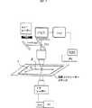
図1は、このような非接触で蛍光強度の検出から温度測定するためのシステムを例示したものである。この例においては、マイクロチップ(1)に形成された微細流路(2)における液相の温度を、蛍光強度の検出として測定可能としており、また、この例では、液相の加熱手段として、IR(赤外線)レーザーの照射手段を例示してもいる。 FIG. 1 illustrates such a system for measuring temperature from detection of fluorescence intensity without contact. In this example, the temperature of the liquid phase in the microchannel (2) formed in the microchip (1) can be measured as fluorescence intensity detection. In this example, as a heating means for the liquid phase, An IR (infrared) laser irradiation means is also exemplified.
システム(装置)としては、微細流路(2)を有するマイクロチップ(1)の配置部とともに、蛍光強度の検知部と、この発光強度から温度を算出する演算部とを備えている。また、図1の例のようにIR(赤外線)レーザー加熱手段を備えることによって、温度条件を精度良くコントロールすることのできる熱反応装置を構成することもできる。 The system (apparatus) includes an arrangement part for the microchip (1) having the fine channel (2), a fluorescence intensity detection part, and a calculation part for calculating the temperature from the emission intensity. In addition, by providing IR (infrared) laser heating means as in the example of FIG. 1, it is possible to configure a thermal reaction apparatus that can control temperature conditions with high accuracy.
反応の検出には、この出願の発明者らが確立した熱レンズ顕微鏡の手段等を採用することができる。 For detecting the reaction, means of a thermal lens microscope established by the inventors of this application can be employed.
<B>の接触方式による温度測定では、マイクロチップの微細流路内の液相に接触する温度検知手段が用いられる。微細流路は、たとえば深さが500μm以下、幅300μm以下と微細であることから、このような微細流路内での液相に対して熱的な影響を及ぼすことがなく、また必要とされる液相の流れに実際的な影響をほとんど与えることがないように、温度検知手段が使用される。 In the temperature measurement by the contact method <B>, a temperature detection means that contacts the liquid phase in the microchannel of the microchip is used. The fine flow path is fine, for example, having a depth of 500 μm or less and a width of 300 μm or less, so that it does not have a thermal effect on the liquid phase in such a fine flow path and is required. The temperature detection means is used so that there is little practical influence on the flow of the liquid phase.
このような温度検知手段としては各種の温度センサーが考慮されるが、この出願の発明においては、その一部または全部がマイクロチップに埋設もしくは載置されるもの、特に、より具体的には、熱電対を好適に使用することができる。 Various temperature sensors are considered as such temperature detection means. In the invention of this application, a part or all of the temperature sensor is embedded or placed in a microchip, and more specifically, A thermocouple can be suitably used.
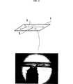
たとえば図2は、熱電対を温度検知手段とし、微細流路(2)に対してその側部に形成した溝(3)にこれを挿入配置して、熱電対が液相に接触するようにした例を示している。写真は、接触部(4)を拡大して例示したものである。実際にも、溝(3)についてはドリル等により形成することができ、K−型熱電対等を使用することができる。図2の例においては、液相との直接接触による影響は実質的にほとんどないものとすることができる。このことは、DNA断片のPCRにおいても確認されている。 For example, in FIG. 2, a thermocouple is used as a temperature detecting means, and this is inserted and disposed in a groove (3) formed on the side of the fine channel (2) so that the thermocouple contacts the liquid phase. An example is shown. The photograph shows an enlarged view of the contact portion (4). Actually, the groove (3) can be formed by a drill or the like, and a K-type thermocouple or the like can be used. In the example of FIG. 2, it can be assumed that there is substantially no influence by direct contact with the liquid phase. This has also been confirmed in PCR of DNA fragments.
図2に例示のように、温度検知手段が組込まれたマイクロチップは、マイクロチップの構成そのものにおいて価値のあるものとなる。 As illustrated in FIG. 2, the microchip in which the temperature detecting means is incorporated is valuable in the configuration of the microchip itself.
赤外線レーザー(IRレーザー)の光熱効果を利用して液相を加熱するこの出願の発明の方法と装置では、流通条件下でマイクロチップ上の酵素反応を迅速かつ局部的に制御することができる。前記の非接触での分光温度検知法を利用して、温度の動的変化と立体的分布を測定し、その結果を数値シミュレーション分析の結果と比較すると、たとえば、この出願の発明の方法と装置では、従来のシステムより30倍、小型化した電熱熱サイクルより3〜6倍速い、それぞれ67℃/sおよび53℃/sという超高速での昇温、冷却速度で操作することができる。赤外線レーザーを使う加熱法の特徴は、電熱加熱によるチップを使った既存のシステムと比べて、加熱対象の大きさが著しく小さく、わずか5nLであるという点にある。熱容量が極めて小さい試料を直接加熱することで迅速な加熱速度を実現することができ、また、ガラス基板を使用することで、これに熱を移すことで熱の除去を効率的に行い、冷却を迅速に行うことができる。温度レベルの再現性は、滞在時間を0.5秒より短くすることで確保される。実際、チップ上の酵素反応は、IRレーザーによる光熱による定期的な加熱によって、たとえば0.6秒の時間分解能で制御することに成功している。IRダイオードレーザーはコンパクトであるため、システムを小型化したデザインに好適である。 In the method and apparatus of the invention of this application in which the liquid phase is heated using the photothermal effect of an infrared laser (IR laser), the enzyme reaction on the microchip can be quickly and locally controlled under the distribution conditions. Using the non-contact spectral temperature detection method, the dynamic change in temperature and the three-dimensional distribution are measured, and the results are compared with the results of numerical simulation analysis. For example, the method and apparatus of the invention of this application Then, it can be operated at ultra-high temperature rise and cooling rates of 67 ° C./s and 53 ° C./s, respectively, 30 times faster than conventional systems and 3-6 times faster than miniaturized electrothermal heat cycles. The feature of the heating method using an infrared laser is that the size of the object to be heated is significantly smaller than that of an existing system using a chip by electrothermal heating, which is only 5 nL. Direct heating of a sample with an extremely small heat capacity can achieve a rapid heating rate, and by using a glass substrate, heat can be transferred to this to efficiently remove heat for cooling. Can be done quickly. The reproducibility of the temperature level is ensured by making the stay time shorter than 0.5 seconds. Actually, the enzyme reaction on the chip has been successfully controlled with a time resolution of 0.6 seconds, for example, by regular heating by photothermal heat from an IR laser. Since the IR diode laser is compact, it is suitable for a design in which the system is miniaturized.
赤外線(IR)レーザーによる加熱は、たとえば図3に例示したように、微細流路に沿って、多点加熱が適宜に、しかも迅速な加熱、冷却のサイクルとして制御可能であるという特徴も有している。 For example, as illustrated in FIG. 3, the heating by the infrared (IR) laser has a feature that multi-point heating can be appropriately controlled as a rapid heating and cooling cycle along the fine flow path. ing.
そこで以下に実施例を示し、さらに詳しくこの出願の発明について説明する。 Then, an Example is shown below and invention of this application is demonstrated in detail.
実施例1
(A)マイクロチップ
図1および図2に例示したようにY形接合点を有する微小チャンネルを公知のエッチング法によって作成した。基板はガラスである。微小チャンネルは幅が250μmで、深さが100μmである。Y形接合点からうしろの反応チャンネルの長さは4.0cmである。Example 1
(A) Microchip As illustrated in FIGS. 1 and 2, a microchannel having a Y-shaped junction was formed by a known etching method. The substrate is glass. The microchannel has a width of 250 μm and a depth of 100 μm. The length of the reaction channel behind the Y-shaped junction is 4.0 cm.
温度測定のために、接合したチップの端からエッチングしたチャンネルに対して直角方向に、ダイヤモンドドリルでサイドチャンネルを図2の場合と同様に設けた。サイドチャンネルは、エッチングしたチャンネルと合流するところまで切削した。交差点は入り口から2cm下流にあるようにした。全体としてエッチングした微小チャンネルの幅は250μm、深さは100μm、そしてサイドチャンネルの直径は500μmとした。
(B)チップ上の化学反応
生化学用の4−アンチアミノピリン(4−AAP)およびN−エチル−N−(2−ヒドロキシ−3−スルフォプロピル)−m−トルイジン(TOOS)は同仁研究所(熊本市)から購入した。大根ペルオキシダーゼ(HRP,EC1.11.1.7、比活性度200単位/mg)および35%過酸化水素水(電子工業用)は、和光純薬(大阪)から購入した。すべての試薬は特に精製を行わずに使用した。水は全実験を通してすべて水精製システム(TW−600RU、野村ミクロサイエンス、神奈川)から得た超純粋水を使用した。基質原液(2×10−3M,4−AAPおよびTOOS;10-1M H2O2)はリン酸塩緩衝液(PBS,pH7.4)によって調製した。これらは冷蔵庫中、10℃で保存し、実験前に適宜PBSで希釈して使用した。HRP溶液(20単位/mL)は固体の酵素から毎日調製し、403nmで吸光度をモニターして濃度を検定し、必要に応じてさらに希釈した。In order to measure the temperature, a side channel was provided with a diamond drill in the direction perpendicular to the etched channel from the end of the bonded chip, as in FIG. The side channel was cut to join the etched channel. The intersection was 2 cm downstream from the entrance. The width of the microchannel etched as a whole was 250 μm, the depth was 100 μm, and the diameter of the side channel was 500 μm.
(B) Chemical reaction on chip 4-antiaminopyrine (4-AAP) and N-ethyl-N- (2-hydroxy-3-sulfopropyl) -m-toluidine (TOOS) for biochemistry are (From Kumamoto City) Radish peroxidase (HRP, EC1.11.1.7,
4−AAPおよびTOOS作業用液の濃度範囲は、2×10⁻⁴M、HRPは1〜5単位/mL、H2O2は1〜5×10-5Mとした。使用直前にHRPと4−AAPとの等体積(各1mL)混合液(溶液1)と、TOOSとH2O2との等体積混合液(溶液2)を調製した。The concentration ranges of 4-AAP and TOOS working solution were 2 × 10⁻⁴ M, HRP was 1 to 5 units / mL, and H2 O2 was 1 to 5 × 10⁻⁵ M. Immediately before use, an equal volume (1 mL each) mixed solution (solution 1) of HRP and 4-AAP and an equal volume mixed solution (solution 2) of TOOS and H2 O2 were prepared.
液体試料の流量調節(0.1〜10μL/分)は、2本のシリンジ(1mL,1710TLL,ハミルトン社製、Reno,NV)を備えたマイクロシリンジポンプ(KDS200,KD Scientific社製,ボストン,マサチューセッツ州)で行った。既に既報に書いたように、シリンジに溶液1および溶液2を入れ、溶融シリカ製毛細管とPTFEコネクターを通して、チップ上のY形接合点上流の2つの入り口から各溶液をマイクロチップに注入した。
(C)赤外線(IR)レーザーによる加熱
微小チャンネルの局所の温度を上げるには、ダイオードレーザー(λc=1472 nm, 150 mW; AF4A212P1, ANRITSU,神奈川)を使用して溶媒を加熱した。IRレーザービームはレンズで収束させ、ウェスト直径が150 μm のビームとした。
プログラム化した加熱実験では、デジタルからアナログに変換する変換ボード(DAC )を搭載したコンピュータでIRレーザーの出力を制御した(PCI-6035, NationalInstruments, オースチン,テキサス州)。
加熱点はY形接合点から下流に向かって1.5cm の所に定めた。反応媒体は流通系で加熱した。4-AAP −TOOS−H2O2−HRP 反応生成物は、さらに5 mm 下流に設けた熱レンズ顕微鏡(TLM )の検出点に連続的に輸送した。
(D)熱レンズ顕微鏡(TLM) による検出
着色反応生成物は、発明者らによってその方法が確立されたTLM で検出した。簡単に述べると、514.5 nm,200 mWで運転し、1025 Hz で機械的に切られるAr+イオンレーザー(SHG-95, Lexel Laser Inc, フリーモント, カリフォルニア州)を励起レーザーとして使用した。反応物質は515 nm付近に弱い吸収しか持たないが、生成物はこの領域に強い吸収を示す(λmax=555 nm,ε=3.2 ×10⁴ M-1 cm-1)。プローブ用レーザーにはHe−Neレーザー(632.8 nm, 5mW; Melles Griot,カールズバッド, カリフォルニア州)を使用した。TLM 信号はアナログ−デジタル変換(ADC )ボードを使用し、サンプリング時間20ミリ秒でデジタル化した。データの取り込みと処理を行うプログラムは、LabView ソフトウェア・パッケージ(National Instrument )を使って書いた。
(E)微小チャンネル内の温度測定
マイクロチップの環境温度は、コントローラ(温度範囲−25〜+99 ℃、精度および安定性±0.1 ℃;PE-60,Linkam Scientific Instruments, Tadworth, U.K. )を備えたペルチエ温度ステージによって保持した。図4に例示したように、サイドチャンネルを持つチップをステージ上に置いた。チップ上の定常状態の温度は、較正した2本の熱電対(クロメル−アルメルタイプ、導線先端直径 25 μm ;安部実装技術研究所(Anbe Soldering Technologies Ltd.), 横浜)でモニタした。熱電対の1本はペルチエステージの上部に、残り1本は500 μm のサイドチャンネルの内側に設置し、エポキシ接着剤でシールした。熱電対の先端は幹線チャンネル内に〜100 μm 突き出した。局部的な光熱加熱効果を裂けるため、先端はIR照射点から1cm上流にあるようにした。典型的には、両センサの温度差が0.2 ℃を超えないようにした。ペルチエステージを備えたマイクロチップは、IR照射光学系に対するマイクロチップの位置が乱れを与えないで液体の取扱いができるよう、しっかり安定させて取り付けた。安定した熱接触が得られるように、2つの熱電対でマイクロチップのバルク温度を絶えずモニタした。
微小チャンネル内の温度変化と空間的な温度分布は蛍光クエンチ法によってモニタした。試料にはローダミン3B染料(Rh-3Bb、Exciton 社(デイトン,オハイオ州)製, )の水溶液(10-5 M)を使用した。蛍光の励起にはAr+イオンレーザー(514.5 nm, 1025 Hz で切る)を使用した。図4に示すように、ショートカットフィルタ(λ50%=570 nm,MellesGriot)とバンドパス・フィルタ(λc=595±10nm,Melles Gropt )で濾光した蛍光は、ロックインアンプ(NF Electronic Instruments 、横浜)とCCD ビデオカメラ(KY-F55B ,日本ビクター株式会社(Victor Co. of Japan Ltd.), 横浜; 分解能480 ×360 画素)に接続したシリコン・ホトダイオード(ET-2010, Electrooptics Technology,トラバーズシティ, ミシガン州)でモニタした。ロックインアンプの時定数は12〜400 msの範囲で変えた。蛍光信号は、TLM 検出の場合と同じようにADC ボードでデジタル化しそれからコンピュータに送った。蛍光画像は、ビデオ・フレームグラバー・ボードを搭載したPCで捕捉した。
(F)結果と考察
<1> まず、Rh-3B 水溶液の螢光クエンチによって、微細流路(チャンネル)内の水が、IRによって局所的に加熱されることを確認した。図4に示す装置で測定した結果、Rh-3B の蛍光強度は溶液温度が高くなるにつれて大きく減少することがわかった。図5は、ペルチエステージでマイクロチップのバルク環境温度を制御して得られた較正曲線を示す。この曲線がAr+イオンレーザーの励起強度に左右されないよう、蛍光強度を10℃における強度に規格化した。測定前にチップの温度を3分間平衡化させ、それからサイドチャンネルに挿入した熱電対の読みの平均値を溶液温度として使用した。このようにして熱電対の読みをモニターした結果、溶液の温度は、検討した流速範囲(0〜5 cm/s )で変化しないことがわかった。水を満たした100 μm の微小チャンネルを通過する固有拡散時間はわずか70 ms に過ぎないため、溶液温度は周囲の基板温度と平衡状態にあった。固有時間に比べて溶液滞在時間ははるかに長いため(検討した最も速い線速度5 cm/s でも0.5 s )、流通条件でさえこのような平衡状態が成立した。
感度は温度の上昇と共に低下するものの、検討した温度範囲(10〜90℃)で観察された強度の低下は5倍を超えた。蛍光強度が低下する原因は、染料分子の励起状態での寿命が短くなるためではないかと思われる。事実、図5に示した蛍光クエンチの結果は、公知の文献に記載されている、よく似た蛍光性分子Rh-Bの、より狭い温度範囲14〜63℃における水溶液データと定量的に一致した。
異なる日に作成した規格化した較正曲線は図3に示したとおり非常に安定しており、RSD は3% であることが確認された。蛍光クエンチ法による温度測定の精度は±0.5 ℃であった。較正曲線は、検討した範囲で溶液の流速には無関係であった。
IR出力が一定の条件で温度上昇ΔTの初期溶液温度Tへの依存性を調べた結果によれば、ΔTは、比例定数ΔT/ T=−0.07℃の関係によって、Tが高くなるにつれて低下した。このことは、1470 nm における水のモル吸光係数が温度の上昇と共に低下するという公知の報告と一致した。水のこうした特性のために、初期温度が異なると、ΔT対IRレーザー出力の依存性が、高いIR出力において、わずかに直線から外れた。しかし、いずれにしても所与の初期温度とIRレーザー出力において、ΔTの再現性はかなり良好であった(RSD =4%)。The flow rate adjustment (0.1 to 10 μL / min) of the liquid sample was performed using a microsyringe pump (KDS200, KD Scientific, Boston, Mass.) Equipped with two syringes (1 mL, 1710TLL, Hamilton, Reno, NV). In the state). As already described,
To raise the temperature of the local heating microchannel by (C) an infrared (IR) laser, a diode laser(λ c = 1472 nm, 150 mW; AF4A212P1, ANRITSU, Kanagawa) using the heated solvent. The IR laser beam was converged with a lens and the waist diameter was 150 μm.
In a programmed heating experiment, the IR laser output was controlled by a computer equipped with a digital to analog conversion board (DAC) (PCI-6035, National Instruments, Austin, TX).
The heating point was set at 1.5 cm downstream from the Y-shaped junction. The reaction medium was heated in the flow system. The 4-AAP-TOOS-H2 O2 -HRP reaction product was continuously transported to the detection point of a thermal lens microscope (TLM) provided further 5 mm downstream.
(D) Detection by thermal lens microscope (TLM) The colored reaction product was detected by TLM, the method of which was established by the inventors. Briefly, an Ar + ion laser (SHG-95, Lexel Laser Inc, Fremont, Calif.) Operating at 514.5 nm, 200 mW and mechanically cut at 1025 Hz was used as the excitation laser. The reactant has only a weak absorption around 515 nm, but the product has a strong absorption in this region (λmax = 555 nm, ε = 3.2 × 10 4 M−1 cm−1 ). A He-Ne laser (632.8 nm, 5 mW; Melles Griot, Carlsbad, CA) was used as the probe laser. The TLM signal was digitized using an analog-to-digital conversion (ADC) board with a sampling time of 20 milliseconds. The data acquisition and processing program was written using the LabView software package (National Instrument).
(E) Temperature measurement in a microchannel The environmental temperature of the microchip was equipped with a controller (temperature range -25 to + 99 ° C, accuracy and stability ± 0.1 ° C; PE-60, Linkam Scientific Instruments, Tadworth, UK) Hold by Peltier temperature stage. As illustrated in FIG. 4, a chip having a side channel was placed on the stage. The steady-state temperature on the chip was monitored by two calibrated thermocouples (Chromel-Alumel type,
The temperature change and spatial temperature distribution in the microchannel were monitored by fluorescence quenching method. An aqueous solution (10−5 M) of rhodamine 3B dye (Rh-3Bb, manufactured by Exciton (Dayton, Ohio)) was used as a sample. An Ar + ion laser (514.5 nm, cut at 1025 Hz) was used for fluorescence excitation. As shown in FIG. 4, the fluorescence filtered with a shortcut filter (λ50% = 570 nm, MellesGriot) and a bandpass filter (λc = 595 ± 10 nm, Melles Gropt) is converted into a lock-in amplifier (NF Electronic Instruments, Yokohama) and a CCD video camera (KY-F55B, Victor Co. of Japan Ltd., Yokohama; resolution 480 x 360 pixels) silicon photodiode (ET-2010, Electrooptics Technology, Travers City) , Michigan). The time constant of the lock-in amplifier was changed in the range of 12 to 400 ms. The fluorescence signal was digitized with an ADC board and sent to a computer as in the case of TLM detection. Fluorescence images were captured with a PC equipped with a video frame grabber board.
(F) Results and discussion
<1> First, it was confirmed that the water in the microchannel (channel) was locally heated by IR by fluorescence quenching of the Rh-3B aqueous solution. As a result of measurement using the apparatus shown in FIG. 4, it was found that the fluorescence intensity of Rh-3B greatly decreased as the solution temperature increased. FIG. 5 shows a calibration curve obtained by controlling the bulk environmental temperature of the microchip at the Peltier stage. The fluorescence intensity was normalized to the intensity at 10 ° C. so that this curve was not affected by the excitation intensity of the Ar+ ion laser. The tip temperature was allowed to equilibrate for 3 minutes before measurement, and then the average value of the thermocouple readings inserted into the side channel was used as the solution temperature. As a result of monitoring the thermocouple reading in this way, it was found that the temperature of the solution did not change in the studied flow rate range (0-5 cm / s). The solution temperature was in equilibrium with the surrounding substrate temperature because the intrinsic diffusion time through a 100 μm microchannel filled with water was only 70 ms. Since the solution residence time is much longer than the intrinsic time (0.5 s even at the fastest linear velocity of 5 cm / s studied), this equilibrium state was established even under the flow conditions.
Although the sensitivity decreased with increasing temperature, the intensity decrease observed over the studied temperature range (10-90 ° C.) exceeded more than 5 times. The cause of the decrease in the fluorescence intensity seems to be because the lifetime of the dye molecules in the excited state is shortened. In fact, the fluorescence quenching results shown in FIG. 5 are quantitatively consistent with the aqueous solution data of the similar fluorescent molecule Rh-B in the narrower temperature range 14-63 ° C. described in the known literature. .
The normalized calibration curve created on different days was very stable as shown in Fig. 3, confirming that the RSD was 3%. The accuracy of temperature measurement by the fluorescence quench method was ± 0.5 ° C. The calibration curve was independent of the solution flow rate in the range studied.
According to the result of investigating the dependence of the temperature rise ΔT on the initial solution temperature T under the condition of a constant IR output, ΔT decreased as T increased due to the relationship of proportionality constant ΔT / T = −0.07 ° C. . This was consistent with the known report that the molar extinction coefficient of water at 1470 nm decreases with increasing temperature. Because of these characteristics of water, the dependence of ΔT versus IR laser power deviated slightly from the straight line at high IR power for different initial temperatures. In any case, however, the reproducibility of ΔT was quite good (RSD = 4%) at a given initial temperature and IR laser power.
<2> 蛍光顕微鏡画像を見ると、IRレーザーをチャンネルに照射したときに局部的に強度が低下していることがはっきりと認められた。溶液の流速を変えたときの温度分布画像を図6に示す。この画像は長さ1 mm 、幅250 μm の微小チャンネルを上から見たものである。各画像の頂部と底部の境が、水とガラスの界面に相当する。マイクロチップはペルチエステージによって一定の温度に保たれ、IRレーザーはチャンネルの所定部分のみを加熱した。もとの強度画像は、10℃で得られた画像で規格化され、各画素に対して得られた蛍光強度比は図5の較正曲線を使ってその温度に変換した。
得られた画像は、チャンネルに沿う空間温度分布が溶液の流速の影響を、明確に反映していることを示した。温度の局部化は低流速に対してIR照射体積と密接に関係し、流速が速くなるほど局部は広がり下流側に移動した。微小チャンネルに沿った空間分布が均一でないことは画像からわかる。これには2つの理由があった:顕微鏡対物レンズの焦点面でのIR強度は空間ガウス分布をとること、水−ガラス界面における基板バルクへの熱移動は効果的に行われること、である。全体として、検討した流速範囲に対して、水−ガラス界面近くの温度はIRビーム中心部の最高温度の40〜50% であった。
この観察は、数値シミュレーションの結果と一致した。事実、画像から、温度分布をチャンネルに沿って詳しく調べてみると、計算された依存性との間に相関性のあることがわかった。数値シミュレーションにおいて、ただ1つのパラメータ、熱源の出力密度を合わせることにより、実験データと計算データとが定量的に一致した。このパラメータの調節は、界面でのIR照射の散乱と反射、およびチップの真の3D形状を考慮するためのものである。
上述の一致によって、ガラス基板への移動が主要な熱の散逸経路であることを確認することが可能となった。すなわち、低流速における拡散による熱移動と、高流速で水が流れる場合は、さらに対流による熱の除去が加わり、この熱移動は促進されることである。<2> From the fluorescence microscope image, it was clearly recognized that the intensity decreased locally when the IR laser was applied to the channel. FIG. 6 shows a temperature distribution image when the flow rate of the solution is changed. This image is a top view of a
The resulting image showed that the spatial temperature distribution along the channel clearly reflected the effect of the solution flow rate. Localization of temperature is closely related to the IR irradiation volume for low flow rates, and the higher the flow rate, the more the local area spreads and moves downstream. It can be seen from the image that the spatial distribution along the microchannel is not uniform. There were two reasons for this: the IR intensity at the focal plane of the microscope objective lens had a spatial Gaussian distribution, and the heat transfer to the substrate bulk at the water-glass interface was effected effectively. Overall, the temperature near the water-glass interface was 40-50% of the maximum temperature at the center of the IR beam for the flow velocity range studied.
This observation was consistent with the numerical simulation results. In fact, from the images, a closer look at the temperature distribution along the channel reveals a correlation with the calculated dependence. In the numerical simulation, by combining only one parameter, the power density of the heat source, the experimental data and the calculated data were quantitatively matched. The adjustment of this parameter is to take into account the scattering and reflection of IR radiation at the interface and the true 3D shape of the chip.
The above agreement made it possible to confirm that the movement to the glass substrate is the main heat dissipation path. That is, when heat flows by diffusion at a low flow rate and when water flows at a high flow rate, heat removal by convection is further added, and this heat transfer is promoted.
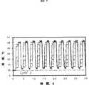
<3> 温度の動的な変化特性を実験的に得るために、ロックインアンプによる検知スキームを使用し、IRビーム中心部の単一スポット測定に蛍光クエンチ法を使用した。蛍光クエンチ法によって測定した温度の迅速サイクリングを図7に示す。10 cycles.3.5s/cycle,dwell time:1.18s per step.である。IRレーザー出力をプログラミングして3種類のレベルサイクルの各サイクルを発生させた。最初のレベルT1はIRレーザーのゼロ出力(0mW)に相当し、最大レベルT3はIRレーザーの最大出力(100mW)に相当する。それに対して中間レベルT2はIRレーザーの出力を変えること(10,20,30,40,60,70,80mW)によって調節した。観測されたサイクル間の温度再現性は、拡散による熱散逸経路に固有の再現性から生じ、後者の再現性はペルチエステージによって一定温度に保たれたガラス基板の熱伝導性の高さによってもたらされた。昇温も冷却も平衡温度に到達した。過不足の問題が完全に排除された。結果として、このシステムは、十分な分解能で滞在時間が1sより短い温度サイクルを生み出すことができる。
温度の上昇下降速度を詳細に検査するため、図8bは、実験的に求めた1s間のIR照射の時間推移を示す。比較のため計算で求めた1s間の照射の推移もあげてある。図から直線近似で得られた実験による昇温速度は67℃/s、冷却速度は53℃/sであった。昇温に対しては100%レベルまで上がるに要する時間(0.4s)、冷却に対しては0%レベルまで下がるに要する時間(0.51s )で温度差ΔT=27℃を割った。実験によって観測されたIRレーザービーム中心部の昇温冷却速度は、検討した条件の範囲内では初期温度および流速には無関係であり、数値解析の結果と良く一致した。
この出願の発明の非接触IRレーザー加熱法によると、観測された極めて迅速な昇温、冷却速度は、他の加熱デバイスに対して報告されているものをしのいでいる。ジュール効果に基づく接触式電熱ヒータを備えたマイクロチップの場合、30℃/sおよび4 ℃/sのそれぞれ昇温速度および冷却速度が実現された。微小チャンネル内の電解質を電熱で直接加熱する方法によって、昇温速度も冷却速度も共に最高20℃まで上げることができたが、加熱される体積は、依然として数μL であった。直接加熱される体積をさらに〜150nL 程度まで減らすと、60℃/sおよび20℃/sのそれぞれ昇温速度および冷却速度が得られた。迅速な昇温冷却速度は、加熱される体積が5nLであって熱容量が2×10-5J/K と小さいこと、そして微小チャンネルの表面積対体積の比が280 cm-1で大きいことによって実現されたものである。開始温度から高い温度への遷移も、また逆の遷移もその実現に1sもかからないため、チップ上の迅速な温度制御が可能になる。送風機や圧縮空気を送るシステムを反復的に使用しなくても、むしろチップ全体は一定の温度に保ったままガラス基板への自然な熱移動によって、迅速な冷却が可能であることは注目に値する。<3> In order to experimentally obtain the dynamic change characteristics of temperature, a detection scheme using a lock-in amplifier was used, and a fluorescence quench method was used for single spot measurement at the center of the IR beam. Rapid cycling of temperature measured by the fluorescence quench method is shown in FIG. 10 cycles.3.5 s / cycle, dwell time: 1.18 s per step. IR laser output was programmed to generate each of the three level cycles. The first level T1 corresponds to the IR laser zero power (0 mW), and the maximum level T3 corresponds to the IR laser maximum power (100 mW). On the other hand, the intermediate level T2 was adjusted by changing the output of the IR laser (10, 20, 30, 40, 60, 70, 80 mW). The observed cycle-to-cycle temperature reproducibility arises from the reproducibility inherent in the heat dissipation path due to diffusion, the latter being caused by the high thermal conductivity of the glass substrate maintained at a constant temperature by the Peltier stage. It was done. Both temperature rise and cooling reached the equilibrium temperature. The problem of excess and deficiency was completely eliminated. As a result, this system can produce a temperature cycle with a dwell time shorter than 1 s with sufficient resolution.
In order to examine in detail the temperature rise and fall speed, FIG. 8b shows the time course of IR irradiation for 1 s obtained experimentally. For comparison, the transition of irradiation during 1 s obtained by calculation is also shown. From the figure, the rate of temperature increase was 67 ° C / s and the rate of cooling was 53 ° C / s, as obtained by linear approximation. The temperature difference ΔT = 27 ° C. was divided by the time required to increase to the 100% level (0.4 s) for the temperature rise and the time required for the cooling to decrease to the 0% level (0.51 s). The heating / cooling rate at the center of the IR laser beam observed in the experiment was irrelevant to the initial temperature and flow velocity within the range of the studied conditions, and agreed well with the results of numerical analysis.
According to the non-contact IR laser heating method of the invention of this application, the extremely rapid heating and cooling rates observed outperform those reported for other heating devices. In the case of a microchip equipped with a contact-type electric heater based on the Joule effect, a heating rate and a cooling rate of 30 ° C / s and 4 ° C / s were realized, respectively. Although the heating rate and the cooling rate were both increased to a maximum of 20 ° C. by the method of directly heating the electrolyte in the microchannel with electric heat, the heated volume was still several μL. When the directly heated volume was further reduced to about -150 nL, a heating rate and a cooling rate of 60 ° C./s and 20 ° C./s were obtained, respectively. Rapid heating / cooling rate is realized by heating volume 5nL, heat capacity as small as 2 × 10⁻⁵ J / K and large channel surface area to volume ratio as large as 280 cm-1 It has been done. Since the transition from the start temperature to the high temperature and the reverse transition does not take 1 s to realize, it is possible to quickly control the temperature on the chip. It is notable that rapid cooling can be achieved by natural heat transfer to the glass substrate while keeping the entire chip at a constant temperature without repeatedly using a blower or a system that sends compressed air. .
<4> 前記のチップ上での化学反応では、微小チャンネル内を流れる溶液の体積がきわめて小さい、IRレーザー加熱デバイスを、流通条件下での化学反応の迅速な温度制御に応用した。微小チャンネル内のIRレーザービームの位置は、Rh-3B 溶液の蛍光を見ながら調節した。シリンジ溶液を変えてもIRレーザーの位置に支障は発生しなかった。加熱の効率は、流すRh-3B 溶液を逐次取り替えることによって検査した。したがって、8:2 水−エタノール混合物で3回(1mL)、それから純水(1mL)でマイクロチップを洗浄したのち、チップ中で酵素反応を行った。
酵素反応の速度は温度が高くなるにつれて速くなるため、ペルチエステージを10℃に冷却して初期速度を低く保った。反応条件は、最適となるように酵素濃度と流速によって調節し、IRレーザー加熱中に発生する反応生成物プラグのきれいなTLM 検出を確保した。要点は、局部加熱に対する感度を十分維持しながら、IRを照射しない時は、生成物の蓄積のバックグラウンドをできるだけ小さくすることであった。最適条件として、HRP 濃度を2.5 単位/mL (溶液1)、H2O2濃度を10-5 M(溶液2)、流速を5μL/分(線速度6.7 mm/s)とした。予備実験から、酵素溶液の原液にIRを連続照射したあとでもHRP 活性度は変わらないことが確認された。
流通条件下で行ったIRレーザー加熱によるチップ上の反応の制御に対する代表的な結果を図9に示す。この実験中IRレーザーは定期的に運転した。レーザーは、指示された時間に対して50% のデューティサイクルでオン・オフした。時間的な推移から、TLM 信号はIR照射のそれと関連した規則的なパターンに従うことがわかった。
1sより短いIR照射時間で反応の迅速な制御データを明らかにするため、TLM 信号を高速でフーリエ変換(FFT )した。TLM 信号から得られる規格化FFT スペクトルを図10に示す。このスペクトルは雑音レベルを超えたシャープな特徴的な周波数を示した。1s および0.6 s の場合、おそらくその周波数で雑音の寄与が増すためと思われるいくつかの高調波が観測された。特徴的な周波数は、使用されるIR照射時間と一致した。このことは、反応速度がIR照射によって外部から制御されることを裏づけている。
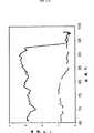
実施例2
図11は、実施例1と同様にして、45サイクルPCRの場合のローダミン−3Bの蛍光強度検知のプロファイルを例示したものである。サイクルは、
IR=120mW,95℃−2s
IR=0mW,68℃−6s
の加熱、冷却のサイクルを示したものである。
実施例3
図2および図4に例示したマイクロチップ内に設けた熱電対による温度検知手段を用いて、DNA meltingの温度変化を観察した。<4> In the chemical reaction on the chip, an IR laser heating device in which the volume of the solution flowing in the microchannel is extremely small was applied to the rapid temperature control of the chemical reaction under the flow conditions. The position of the IR laser beam in the microchannel was adjusted while observing the fluorescence of the Rh-3B solution. Changing the syringe solution did not interfere with the IR laser position. The efficiency of heating was checked by sequentially changing the flowing Rh-3B solution. Therefore, the microchip was washed three times with an 8: 2 water-ethanol mixture (1 mL) and then with pure water (1 mL), and then the enzyme reaction was performed in the chip.
Since the rate of the enzymatic reaction increased with increasing temperature, the Peltier stage was cooled to 10 ° C. to keep the initial rate low. The reaction conditions were adjusted for optimal conditions by enzyme concentration and flow rate to ensure clean TLM detection of reaction product plugs generated during IR laser heating. The main point was to keep the product accumulation background as small as possible when not irradiating IR while maintaining sufficient sensitivity to local heating. As optimum conditions, the HRP concentration was 2.5 units / mL (solution 1), the H2 O2 concentration was 10−5 M (solution 2), and the flow rate was 5 μL / min (linear velocity: 6.7 mm / s). Preliminary experiments confirmed that the HRP activity did not change even after continuous IR irradiation of the enzyme solution.
FIG. 9 shows a typical result for controlling the reaction on the chip by IR laser heating performed under the flow conditions. During this experiment, the IR laser was operated regularly. The laser was turned on and off with a 50% duty cycle for the indicated time. The time course shows that the TLM signal follows a regular pattern associated with that of IR irradiation.
The TLM signal was Fourier-transformed (FFT) at high speed in order to clarify the rapid control data of the reaction with IR irradiation time shorter than 1 s. A normalized FFT spectrum obtained from the TLM signal is shown in FIG. This spectrum showed a sharp characteristic frequency above the noise level. In the case of 1 s and 0.6 s, several harmonics were observed, probably due to increased noise contribution at that frequency. The characteristic frequency was consistent with the IR irradiation time used. This confirms that the reaction rate is externally controlled by IR irradiation.
Example 2
FIG. 11 illustrates the fluorescence intensity detection profile of rhodamine-3B in the case of 45 cycle PCR in the same manner as in Example 1. Cycle
IR = 120mW, 95 ° C-2s
IR = 0mW, 68 ° C-6s
This shows the heating and cooling cycle.
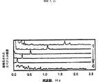
Example 3
The temperature change of DNA melting was observed using a temperature detection means by a thermocouple provided in the microchip illustrated in FIGS.
ds−DNA特異染料 SYBER−GreenIで標識されたPCR増幅後のDNA断片を微小チャンネル内に導入し、外部加熱手段によって60から98℃に加熱した。昇温速度は0.2℃/sとした。 The DNA fragment after PCR amplification labeled with ds-DNA specific dye SYBER-Green I was introduced into a microchannel and heated to 60 to 98 ° C. by an external heating means. The heating rate was 0.2 ° C./s.
Ar+イオンレーザー(488nm、100mW)を蛍光励起源として用いた。Ar+ ion laser (488 nm, 100 mW) was used as the fluorescence excitation source.
図12は、DNA meltingの結果を示したものである。実線は500bpのλ−ファージDNA断片の場合を、破線はNTC(negative templatecontrol) 試料の場合を示している。 FIG. 12 shows the result of DNA melting. The solid line indicates the case of a 500 bp λ-phage DNA fragment, and the broken line indicates the case of an NTC (negative template control) sample.
温度検知手段としてのチップ埋込み型の熱電対が有効であることが確認された。 It was confirmed that a chip-embedded thermocouple as a temperature detecting means is effective.
以上詳しく説明したとおり、この出願の発明によって、マイクロチップの微細流路内の液相温度を精度よく測定することができ、また迅速に、かつ適切に温度制御することのできる新しい技術手段を提供することができる。 As described above in detail, the invention of this application provides a new technical means capable of accurately measuring the liquid phase temperature in the microchannel of the microchip and capable of controlling the temperature quickly and appropriately. can do.
Claims (2)
Translated fromJapaneseApplications Claiming Priority (3)
| Application Number | Priority Date | Filing Date | Title |
|---|---|---|---|
| JP2001136668 | 2001-05-07 | ||
| JP2001136668 | 2001-05-07 | ||
| PCT/JP2001/010450WO2002090912A1 (en) | 2001-05-07 | 2001-11-29 | Methods for measuring and controlling the temperature of liquid phase in micro passage of microchip, device for the methods, and microchip |
Publications (2)
| Publication Number | Publication Date |
|---|---|
| JPWO2002090912A1 JPWO2002090912A1 (en) | 2004-08-26 |
| JP4166091B2true JP4166091B2 (en) | 2008-10-15 |
Family
ID=18983905
Family Applications (1)
| Application Number | Title | Priority Date | Filing Date |
|---|---|---|---|
| JP2002588124AExpired - Fee RelatedJP4166091B2 (en) | 2001-05-07 | 2001-11-29 | Microchip thermal reactor |
Country Status (2)
| Country | Link |
|---|---|
| JP (1) | JP4166091B2 (en) |
| WO (1) | WO2002090912A1 (en) |
Cited By (1)
| Publication number | Priority date | Publication date | Assignee | Title |
|---|---|---|---|---|
| WO2016121929A1 (en)* | 2015-01-30 | 2016-08-04 | 株式会社ニコン | Fluid device, temperature control device, temperature control method, nucleic acid amplification device, and nucleic acid amplification method |
Families Citing this family (10)
| Publication number | Priority date | Publication date | Assignee | Title |
|---|---|---|---|---|
| JP2006145516A (en)* | 2004-07-14 | 2006-06-08 | Ebara Corp | Microchannel chip reaction control system, micro total reaction system having the same, and micro total analysis system |
| JP4691959B2 (en)* | 2004-11-04 | 2011-06-01 | 横河電機株式会社 | Temperature measuring device |
| JP2006130599A (en)* | 2004-11-05 | 2006-05-25 | Yokogawa Electric Corp | Microchannel device |
| JP4878223B2 (en) | 2006-06-16 | 2012-02-15 | 国立大学法人東京農工大学 | Method and apparatus for detecting interaction between nucleic acid and protein |
| JP4947520B2 (en)* | 2007-07-04 | 2012-06-06 | 国立大学法人東京農工大学 | Method and apparatus for detecting small biomolecules |
| JP2009069011A (en)* | 2007-09-13 | 2009-04-02 | Sony Corp | Reaction control apparatus and method |
| JP2009097902A (en)* | 2007-10-15 | 2009-05-07 | Sony Corp | Reaction control device and reaction control method |
| CN104854451B (en)* | 2012-10-09 | 2018-04-06 | 犹他大学研究基金会 | With fluorescence monitoring temperature |
| JP6229505B2 (en)* | 2014-01-15 | 2017-11-15 | 富士レビオ株式会社 | Temperature control system |
| JP6631867B2 (en)* | 2015-02-06 | 2020-01-15 | パナソニックIpマネジメント株式会社 | Method for measuring temperature of liquid in microchannel |
Family Cites Families (2)
| Publication number | Priority date | Publication date | Assignee | Title |
|---|---|---|---|---|
| JPH09262084A (en)* | 1996-03-27 | 1997-10-07 | Technol Res Assoc Of Medical & Welfare Apparatus | Dna amplifying apparatus |
| JP2000029541A (en)* | 1998-07-15 | 2000-01-28 | Hitachi Ltd | Temperature control device |
- 2001
- 2001-11-29WOPCT/JP2001/010450patent/WO2002090912A1/enactiveApplication Filing
- 2001-11-29JPJP2002588124Apatent/JP4166091B2/ennot_activeExpired - Fee Related
Cited By (1)
| Publication number | Priority date | Publication date | Assignee | Title |
|---|---|---|---|---|
| WO2016121929A1 (en)* | 2015-01-30 | 2016-08-04 | 株式会社ニコン | Fluid device, temperature control device, temperature control method, nucleic acid amplification device, and nucleic acid amplification method |
Also Published As
| Publication number | Publication date |
|---|---|
| WO2002090912A1 (en) | 2002-11-14 |
| JPWO2002090912A1 (en) | 2004-08-26 |
Similar Documents
| Publication | Publication Date | Title |
|---|---|---|
| US8409848B2 (en) | System and method for rapid thermal cycling | |
| Tanaka et al. | Non-contact photothermal control of enzyme reactions on a microchip by using a compact diode laser | |
| JP4166091B2 (en) | Microchip thermal reactor | |
| US6537799B2 (en) | Electrical current for controlling fluid parameters in microchannels | |
| US6174675B1 (en) | Electrical current for controlling fluid parameters in microchannels | |
| AU746098B2 (en) | Microfluidic system with electrofluidic and electrothermal controls | |
| RU2385940C1 (en) | Method for real-time detection of nucleic acids by polymerase chain reaction and device for implementation thereof | |
| JP3932368B2 (en) | Plasma generator | |
| WO1999039005A1 (en) | Rapid thermocycling for sample analysis | |
| JP2024052866A (en) | Infrared analysis chip and infrared imaging device | |
| US20150017648A1 (en) | Devices, systems and methods for thermal control of droplet detection | |
| Nabuti et al. | Highly efficient photonic PCR system based on plasmonic heating of gold nanofilms | |
| US6022141A (en) | Apparatus and method for remote temperature measurements | |
| WO1999039120A1 (en) | Thermal expansion-induced fluid control for microfluidic devices | |
| US10914660B2 (en) | Apparatus and method for optothermal heating of nanoscale environments | |
| JP2010139491A (en) | Method for measuring temperature of reaction liquid, apparatus for measuring temperature of reaction liquid, apparatus for adjusting temperature of reaction liquid, and apparatus for bringing genes into amplification reaction | |
| US20210023565A1 (en) | Reaction apparatus and temperature control method | |
| US20040131504A1 (en) | Remote temperature sensing of small volume and related apparatus thereof | |
| CN101735949A (en) | variable temperature device | |
| WO2007052925A1 (en) | Measuring apparatus | |
| JP4199225B2 (en) | Method and apparatus for regulating fluid temperature | |
| Gomez et al. | Microchip electrophoresis tools for the analysis of small molecules | |
| Haab et al. | Single-molecule DNA detection in microfabricated capillary electrophoresis chips | |
| JP4635728B2 (en) | Microchip inspection device | |
| KR100792296B1 (en) | Apparatus and Method for Detecting Biocombination Using Peltier Devices |
Legal Events
| Date | Code | Title | Description |
|---|---|---|---|
| A621 | Written request for application examination | Free format text:JAPANESE INTERMEDIATE CODE: A621 Effective date:20040916 | |
| A131 | Notification of reasons for refusal | Free format text:JAPANESE INTERMEDIATE CODE: A131 Effective date:20070807 | |
| A521 | Request for written amendment filed | Free format text:JAPANESE INTERMEDIATE CODE: A523 Effective date:20071009 | |
| TRDD | Decision of grant or rejection written | ||
| A01 | Written decision to grant a patent or to grant a registration (utility model) | Free format text:JAPANESE INTERMEDIATE CODE: A01 Effective date:20080708 | |
| A01 | Written decision to grant a patent or to grant a registration (utility model) | Free format text:JAPANESE INTERMEDIATE CODE: A01 | |
| A61 | First payment of annual fees (during grant procedure) | Free format text:JAPANESE INTERMEDIATE CODE: A61 Effective date:20080729 | |
| R150 | Certificate of patent or registration of utility model | Free format text:JAPANESE INTERMEDIATE CODE: R150 | |
| FPAY | Renewal fee payment (event date is renewal date of database) | Free format text:PAYMENT UNTIL: 20110808 Year of fee payment:3 | |
| FPAY | Renewal fee payment (event date is renewal date of database) | Free format text:PAYMENT UNTIL: 20120808 Year of fee payment:4 | |
| FPAY | Renewal fee payment (event date is renewal date of database) | Free format text:PAYMENT UNTIL: 20130808 Year of fee payment:5 | |
| FPAY | Renewal fee payment (event date is renewal date of database) | Free format text:PAYMENT UNTIL: 20130808 Year of fee payment:5 | |
| S533 | Written request for registration of change of name | Free format text:JAPANESE INTERMEDIATE CODE: R313533 | |
| R350 | Written notification of registration of transfer | Free format text:JAPANESE INTERMEDIATE CODE: R350 | |
| R250 | Receipt of annual fees | Free format text:JAPANESE INTERMEDIATE CODE: R250 | |
| R250 | Receipt of annual fees | Free format text:JAPANESE INTERMEDIATE CODE: R250 | |
| R250 | Receipt of annual fees | Free format text:JAPANESE INTERMEDIATE CODE: R250 | |
| R250 | Receipt of annual fees | Free format text:JAPANESE INTERMEDIATE CODE: R250 | |
| R250 | Receipt of annual fees | Free format text:JAPANESE INTERMEDIATE CODE: R250 | |
| S111 | Request for change of ownership or part of ownership | Free format text:JAPANESE INTERMEDIATE CODE: R313113 | |
| R360 | Written notification for declining of transfer of rights | Free format text:JAPANESE INTERMEDIATE CODE: R360 | |
| R360 | Written notification for declining of transfer of rights | Free format text:JAPANESE INTERMEDIATE CODE: R360 | |
| R371 | Transfer withdrawn | Free format text:JAPANESE INTERMEDIATE CODE: R371 | |
| S111 | Request for change of ownership or part of ownership | Free format text:JAPANESE INTERMEDIATE CODE: R313113 | |
| R350 | Written notification of registration of transfer | Free format text:JAPANESE INTERMEDIATE CODE: R350 | |
| LAPS | Cancellation because of no payment of annual fees |