JP4165042B2 - Image layout evaluation method, image layout evaluation system, and image layout evaluation processing program - Google Patents
Image layout evaluation method, image layout evaluation system, and image layout evaluation processing programDownload PDFInfo
- Publication number
- JP4165042B2 JP4165042B2JP2001213424AJP2001213424AJP4165042B2JP 4165042 B2JP4165042 B2JP 4165042B2JP 2001213424 AJP2001213424 AJP 2001213424AJP 2001213424 AJP2001213424 AJP 2001213424AJP 4165042 B2JP4165042 B2JP 4165042B2
- Authority
- JP
- Japan
- Prior art keywords
- layout
- image
- equipotential
- complexity
- layout evaluation
- Prior art date
- Legal status (The legal status is an assumption and is not a legal conclusion. Google has not performed a legal analysis and makes no representation as to the accuracy of the status listed.)
- Expired - Fee Related
Links
Images


Classifications
- G—PHYSICS
- G06—COMPUTING OR CALCULATING; COUNTING
- G06T—IMAGE DATA PROCESSING OR GENERATION, IN GENERAL
- G06T7/00—Image analysis
- G06T7/60—Analysis of geometric attributes
- G—PHYSICS
- G06—COMPUTING OR CALCULATING; COUNTING
- G06T—IMAGE DATA PROCESSING OR GENERATION, IN GENERAL
- G06T11/00—2D [Two Dimensional] image generation
- G06T11/60—Editing figures and text; Combining figures or text
- G—PHYSICS
- G06—COMPUTING OR CALCULATING; COUNTING
- G06T—IMAGE DATA PROCESSING OR GENERATION, IN GENERAL
- G06T7/00—Image analysis
- G06T7/0002—Inspection of images, e.g. flaw detection
- G—PHYSICS
- G06—COMPUTING OR CALCULATING; COUNTING
- G06T—IMAGE DATA PROCESSING OR GENERATION, IN GENERAL
- G06T2207/00—Indexing scheme for image analysis or image enhancement
- G06T2207/30—Subject of image; Context of image processing
- G06T2207/30108—Industrial image inspection
- G06T2207/30144—Printing quality
Landscapes
- Engineering & Computer Science (AREA)
- Physics & Mathematics (AREA)
- General Physics & Mathematics (AREA)
- Theoretical Computer Science (AREA)
- Computer Vision & Pattern Recognition (AREA)
- Geometry (AREA)
- Quality & Reliability (AREA)
- Processing Or Creating Images (AREA)
- Document Processing Apparatus (AREA)
- Editing Of Facsimile Originals (AREA)
Description
Translated fromJapanese【0001】
【発明の属する技術分野】
本発明は文字や写真、絵、図形など(これら文字や写真、絵、図形などをまとめて画像という)のレイアウトの評価を行い、それによって、見易く内容の理解のし易いレイアウトを可能とする画像レイアウト評価方法および画像レイアウト評価システムならびに画像レイアウト評価処理プログラムに関する。
【0002】
【従来の技術】
情報機器の表示画面や看板、ポスタなど限られた表示範囲内に文字や写真、絵、図形などの画像を表示する場合、多くの人に読みやすく、また、その内容を理解し易くレイアウトすることは重要であり、従来、これらのレイアウトは、専門のデザイナによってなされることが多い。
【0003】
一方、文字列については、印刷の組み版などの仕様(たとえば、JIS規格のX4051の規定)があり、全面的に自動化とは言えないまでも、かなり自動化が進んでおり、それなりのレイアウトとすることは可能であった。
【0004】
【発明が解決しようとする課題】
しかし、文字だけでなく写真、絵、図形を含む画像一般について、機械的にレイアウトを決めることは難しく、人間の直感などに頼らざるを得ないのが実情である。
【0005】
特に、写真、絵、図形などが文字列のなかに存在するような複数種類の要素で構成される画像のレイアウトは、専門のデザイナなどが決めないと、読みやすく、その内容を理解し易いレイアウトとならない場合が多い。
【0006】
これに対処するために、電子化されたデータを用いて、たとえば、新聞紙面などを自動的に作成するシステムなども運用されつつある。
【0007】
しかし、このシステムは予めデザイナがレイアウトした雛形(テンプレート)に、文章や写真などの電子データを当てはめて行く方式であり、規定外のデータを無理矢理入れようとすると、レイアウトが破綻する場合があるため、適応できる範囲が限られている。また、このシステムは、新聞なら新聞用、雑誌なら雑誌用というように、用途別にテンプレートを用意しておかなければならないという問題もある。
【0008】
また、このようなテンプレートはあくまでデザイナなどが作成するものであるため、デザイナ個人の嗜好の影響が現れたものとなりがちで、そのテンプレートによって作成されたレイアウトが万人向けのレイアウトになるとは限らない。
【0009】
そこで本発明は、文字、写真、絵、図形などの画像を限られた表示範囲内にレイアウトする際、そのレイアウト評価を定量的に行えるようにし、これまで、人間の直感や手作業にたよっていた画像のレイアウトを自動的に最適化することができるようすることを目的とする。
【0010】
【課題を解決するための手段】
上述した目的を達成するために、本発明の画像レイアウト評価方法は、所定の表示範囲内にあるレイアウトで表示されるひとまとまりの画像のレイアウト評価を行う画像レイアウト評価方法において、前記レイアウト対象となるひとまとまりの画像に対し、そのひとまとまりの画像を所定のレイアウトとし、そのレイアウトされたひとまとまりの画像に対して、視覚の誘導場を計算し、求められた視覚の誘導場から等ポテンシャル線を得て、その等ポテンシャル線の形状に基づいてそのレイアウトの良し悪しを評価している。
【0011】
この画像レイアウト評価方法において、前記ひとまとまりの画像に文字が含まれる場合には、その文字列を線で表し、前記ひとまとまりの画像に写真、絵、図形などが含まれる場合には、これらを外枠で表して、前記視覚の誘導場を計算するようにしている。
【0012】
また、この画像レイアウト評価方法において、前記等ポテンシャル線の形状に基づいてレイアウトの良し悪しを評価するに至るまでの処理は、まず、ユーザが任意に設定したレイアウトを初期レイアウトとし、その初期レイアウトに対し、前記等ポテンシャル線を得る処理を行って、その等ポテンシャル線の形状から前記レイアウトの良し悪しを評価し、そのレイアウトが最適なレイアウトでなければ、前記初期レイアウトからレイアウトを順次変えて、それぞれのレイアウトごとに、前記等ポテンシャル線をそれぞれ得て、その等ポテンシャル線の形状から前記レイアウトの良し悪しを評価する処理であって、その処理を最適なレイアウトが得られるまで行うようにしてもよい。
【0013】
また、この画像レイアウト評価方法において、前記等ポテンシャル線の形状に基づいてレイアウトの良し悪しを評価するに至るまでの処理は、まず、あるレイアウトを設定するためのテンプレートを予め用意し、そのテンプレートに従ったレイアウトを初期レイアウトとし、その初期レイアウトに対し、前記等ポテンシャル線を得る処理を行って、その等ポテンシャル線の形状から前記レイアウトの良し悪しを評価し、そのレイアウトが最適なレイアウトでなければ、前記初期レイアウトからレイアウトを順次変えて、それぞれのレイアウトごとに、前記等ポテンシャル線をそれぞれ得て、その等ポテンシャル線の形状から前記レイアウトの良し悪しを評価する処理であって、その処理を最適なレイアウトが得られるまで行うようにしてもよい。
【0014】
また、この情報レイアウト評価方法において、前記ひとまとまりの画像が複数種類の要素で構成される場合、それぞれの要素に対し、レイアウトを行う上で必要な特性を示す属性を記述しておき、前記最適なレイアウトを得る処理を行う際にその属性を参照するようにしている。
【0015】
また、この画像レイアウト評価方法において、前記テンプレートは、前記それぞれの要素に対し、レイアウトを行う上で必要な特性を示す属性が記述されている場合、その属性に対応付けられたレイアウトを可能とするテンプレートとしている。
【0016】
また、この画像レイアウト評価方法において、前記等ポテンシャル線の形状から前記レイアウトの良し悪しを評価する処理は、前記等ポテンシャル線の凹凸の多さを判断し、凹凸の少ない等ポテンシャル線の得られるレイアウトをよいレイアウトであるとする。
【0017】
また、前記等ポテンシャル線の凹凸の多さは、等ポテンシャル線の複雑度として求め、その複雑度は、当該等ポテンシャル線の長さに対する当該等ポテンシャル線で囲まれる面の面積の関係から求めるようにしている。
【0018】
また、そのときの複雑度は、その値が小さいほど複雑度は小さいとし、最小の複雑度が得られるレイアウトを最適なレイアウトしている。
【0019】
また、本発明の画像レイアウト評価システムにおいて、所定の表示範囲内にあるレイアウトで表示されるひとまとまりの画像のレイアウト評価を行う画像レイアウト評価システムにおいて、レイアウト対象となるひとまとまりの画像に対して視覚の誘導場を計算し、求められた視覚の誘導場から等ポテンシャル線を求める視覚の誘導場計算手段と、この視覚の誘導場計算手段で求められた等ポテンシャル線に基づいてレイアウトの良し悪しを評価するレイアウト評価手段とを有し、前記レイアウト対象となるひとまとまりの画像に対し、そのひとまとまりの画像を所定のレイアウトとし、そのレイアウトされたひとまとまりの画像に対して、視覚の誘導場を計算し、求められた視覚の誘導場から等ポテンシャル線を得て、その等ポテンシャル線の形状に基づいてそのレイアウトの良し悪しを評価するようにしている。
【0020】
この画像レイアウト評価システムにおいて、前記視覚の誘導場計算手段は、前記ひとまとまりの画像に文字が含まれる場合には、その文字列を線で表し、前記ひとまとまりの画像に写真、絵、図形などが含まれる場合には、これらを外枠で表して、前記視覚の誘導場を計算するようにしている。
【0021】
また、この画像レイアウト評価システムにおいて、前記等ポテンシャル線の形状に基づいてレイアウトの良し悪しを評価するに至るまでの処理は、まず、ユーザが任意に設定したレイアウトを初期レイアウトとし、その初期レイアウトに対し、前記視覚の誘導場計算手段が等ポテンシャル線を得る処理を行って、その等ポテンシャル線の形状に基づいて前記レイアウト評価手段が前記レイアウトの良し悪しを評価し、そのレイアウトが最適なレイアウトでなければ、前記初期レイアウトからレイアウトを順次変えて、それぞれのレイアウトごとに、前記等ポテンシャル線をそれぞれ得て、その等ポテンシャル線の形状に基づいてレイアウトの良し悪しを評価する処理であって、その処理を最適なレイアウトが得られるまで行うようにしてもよい。
【0022】
また、この画像レイアウト評価システムにおいて、前記等ポテンシャル線の形状に基づいてレイアウトの良し悪しを評価するに至るまでの処理は、まず、あるレイアウトを設定するためのテンプレートを取得し、そのテンプレートに従ったレイアウトを初期レイアウトとし、その初期レイアウトに対し、前記視覚の誘導場計算手段が等ポテンシャル線を得る処理を行って、その等ポテンシャル線の形状に基づいて前記レイアウト評価手段が前記レイアウトの良し悪しを評価し、そのレイアウトが最適なレイアウトでなければ、前記初期レイアウトからレイアウトを順次変えて、それぞれのレイアウトごとに、前記等ポテンシャル線をそれぞれ得て、その等ポテンシャル線の形状に基づいてレイアウトの良し悪しを評価する処理であって、その処理を最適なレイアウトが得られるまで行うようにしてもよい。
【0023】
また、この画像レイアウト評価システムにおいて、前記ひとまとまりの画像が複数種類の要素で構成される場合、前記レイアウト評価手段は、それぞれの要素に対し、レイアウトを行う上で必要な特性を示す属性を知識として有し、前記最適なレイアウトを得る処理を行う際にその属性を参照するようにしている。
【0024】
また、この画像レイアウト評価システムにおいて、前記テンプレートは、前記それぞれの要素に対し、レイアウトを行う上で必要な特性を示す属性が記述されている場合、その属性に対応付けられたレイアウトを可能とするテンプレートとしている。
【0025】
また、この画像レイアウト評価システムにおいて、前記レイアウト評価手段が行う等ポテンシャル線の形状から前記レイアウトの良し悪しを評価する処理は、前記等ポテンシャル線の凹凸の多さを判断し、凹凸の少ない等ポテンシャル線の得られるレイアウトをよいレイアウトとしている。
【0026】
また、前記等ポテンシャル線の凹凸の多さは、等ポテンシャル線の複雑度として求め、その複雑度は、当該等ポテンシャル線の長さに対する当該等ポテンシャル線で囲まれる面の面積の関係から求めるようにする。
【0027】
このとき、前記複雑度は、その値が小さいほど複雑度は小さいとし、最小の複雑度が得られるレイアウトを最適なレイアウトとしている。
【0028】
また、本発明の画像レイアウト評価処理プログラムは、所定の表示範囲内にあるレイアウトで表示されるひとまとまりの画像のレイアウト評価を行う画像レイアウト評価処理プログラムであって、その処理プログラムは、前記レイアウト対象となるひとまとまりの画像に対し、そのひとまとまりの画像を所定のレイアウトとし、そのレイアウトされたひとまとまりの画像に対して、視覚の誘導場を計算する手順と、求められた視覚の誘導場から等ポテンシャル線を得て、その等ポテンシャル線の形状に基づいてそのレイアウトの良し悪しを評価する手順とを含むものである。
【0029】
この画像レイアウト評価処理プログラムにおいて、前記ひとまとまりの画像に文字が含まれる場合には、その文字列を線で表し、前記ひとまとまりの画像に写真、絵、図形などが含まれる場合には、これらを外枠で表して、前記視覚の誘導場を計算するようにしている。
【0030】
また、この画像レイアウト評価処理プログラムにおいて、前記等ポテンシャル線の形状からレイアウトの良し悪しを評価するに至るまでの処理は、まず、ユーザが任意に設定したレイアウトを初期レイアウトとし、その初期レイアウトに対し、前記等ポテンシャル線を得る処理を行って、その等ポテンシャル線の形状から前記レイアウトの良し悪しを評価し、そのレイアウトが最適なレイアウトでなければ、前記初期レイアウトからレイアウトを順次変えて、それぞれのレイアウトごとに、前記等ポテンシャル線をそれぞれ得て、その等ポテンシャル線の形状から前記レイアウトの良し悪しを評価する処理であって、その処理を最適なレイアウトが得られるまで行うようにしてもよい。
【0031】
また、この画像レイアウト評価処理プログラムにおいて、前記等ポテンシャル線の形状から前記レイアウトの良し悪しを評価するに至るまでの処理は、まず、ユーザが任意に設定したレイアウトを初期レイアウトとし、その初期レイアウトに対し、前記等ポテンシャル線を得る処理を行って、その等ポテンシャル線の形状から前記レイアウトの良し悪しを評価し、そのレイアウトが最適なレイアウトでなければ、前記初期レイアウトからレイアウトを順次変えて、それぞれのレイアウトごとに、前記等ポテンシャル線をそれぞれ得て、その等ポテンシャル線の形状から前記レイアウトの良し悪しを評価する処理であって、その処理を最適なレイアウトが得られるまで行うようにしてもよい。
【0032】
また、この画像レイアウト評価処理プログラムにおいて、前記ひとまとまりの画像が複数種類の要素で構成される場合、それぞれの要素に対し、レイアウトを行う上で必要な特性を示す属性を記述しておき、前記最適なレイアウトを得る処理を行う際にその属性を参照するようにしている。
【0033】
また、この画像レイアウト評価処理プログラムにおいて、前記テンプレートは、前記それぞれの要素に対し、レイアウトを行う上で必要な特性を示す属性が記述されている場合、その属性に対応付けられたレイアウトを可能とするテンプレートとしている。
【0034】
また、この画像レイアウト評価処理プログラムを記録した記録媒体において、前記等ポテンシャル線の形状から前記レイアウトの良し悪しを評価する処理は、前記等ポテンシャル線の凹凸の多さを判断し、凹凸の少ない等ポテンシャル線の得られるレイアウトをよいレイアウトとしている。
【0035】
また、前記等ポテンシャル線の凹凸の多さは、等ポテンシャル線の複雑度として求め、その複雑度は、当該等ポテンシャル線の長さに対する当該等ポテンシャル線で囲まれる面の面積の関係から求めるようにしている。
【0036】
このとき、前記複雑度は、その値が小さいほど複雑度は小さいとし、最小の複雑度が得られるレイアウトを最適なレイアウトしている。
【0037】
このように本発明では、レイアウト対象となるひとまとまりの画像に対して、視覚の誘導場を計算し、求められた視覚の誘導場から等ポテンシャル線を得て、その等ポテンシャル線の形状からそのレイアウトの良し悪しを評価するようにしているので、レイアウト評価を定量的に行うことができ、それを利用することによって、人間の直感や手作業にたよっていたレイアウトを自動的に最適化することが可能となる。
【0038】
また、視覚の誘導場を計算する際は、文字列を線で表し、写真、絵、図形などを外枠で表して視覚の誘導場を計算するようにしているので、視覚の誘導場の計算を単純化することができ、高速な処理が可能となる。
【0039】
また、等ポテンシャル線の形状からレイアウトの良し悪しを評価するに至るまでの処理としては、ユーザが任意に設定したレイアウトを初期レイアウトとして、その初期レイアウトから少しずつレイアウトを変えながら、それぞれのレイアウトにおける等ポテンシャル線を得て、得られたそれぞれの等ポテンシャル線の形状に基づいて前記レイアウトの良し悪しを評価する手法、あるいは、あるレイアウトを設定するためのテンプレートを予め用意し、そのテンプレートに従ったレイアウトを初期レイアウトとし、その初期レイアウトから少しずつレイアウトを変えながら、それぞれのレイアウトにおける等ポテンシャル線を得て、得られたそれぞれの等ポテンシャル線の形状に基づいて前記レイアウトの良し悪しを評価する手法がある。
【0040】
これらの手法は、ユーザ側とシステム側にどこまで処理を委ねるかによって選択できるもので、前者の手法では、ユーザ側に多少の操作負担がかかるが、システム側が行う処理を単純なものとすることができる利点があり、一方、後者の手法は、テンプレートによって、とりあえず、おおまかなレイアウトを設定し、そのおおまかなレイアウトを基に最適なレイアウトが得られるまでレイアウトを徐々に変えて行けばよいので、最適なレイアウトが得られるまでの時間を大幅に短縮できる可能性が高くなり、ユーザの操作負担を大幅に軽減できる利点がある。なお、ここで用いるテンプレートは、デザイナなどが厳密に作成したテンプレートである必要はなく、おおまかなレイアウトが行える程度のものでよい。
【0041】
また、レイアウト対象となるひとまとまりの画像が複数種類の要素で構成される場合、それぞれの要素に対し、レイアウトを行う上で必要な特性を示す属性(このデータはタイトル、このデータは本文、このデータはどの本文とリンクしているかなどを示す情報)を記述しておき、前記最適なレイアウトを選択する際にその属性を参照するようにしているので、レイアウトされた内容に不具合(たとえば、始めに来るべき見出しがあとになってしまったり、その見出しに対する文章が見出しとかけ離れた位置になったり、写真とそれに関する文章がかけ離れた位置となってしまうといった不具合)をなくすことができる。
【0042】
また、それぞれの要素に対し、レイアウトを行う上で必要な特性を示す属性が記述されている場合、初期レイアウトとして用いるテンプレートは、その属性に対応付けられたレイアウトを可能とするテンプレートとすることによって、レイアウトされた内容に上述したような不具合が生じるのを防ぐことができる。
【0043】
また、等ポテンシャル線の形状から前記レイアウトの良し悪しを評価する処理は、等ポテンシャル線の凹凸の多さを判断し、凹凸の少ない等ポテンシャル線の得られるレイアウトをよいレイアウトとしているので、レイアウト評価を定量的にかつ適正に行うことができる。
【0044】
また、等ポテンシャル線の凹凸の多さは、等ポテンシャル線の複雑度として求め、その複雑度は、当該等ポテンシャル線の長さに対する当該等ポテンシャル線で囲まれる面の面積の関係から求めるようにしているので、簡単な計算で等ポテンシャル線の凹凸の多さを判断することができる。
【0045】
そして、その複雑度は、その値が小さいほど複雑度は小さいとし、最小の複雑度が得られるレイアウトを最適なレイアウトするようにしているので、簡単にしかも適切なレイアウト評価を行うことができる。
【0046】
【発明の実施の形態】
以下、本発明の実施の形態について説明する。なお、この実施の形態で説明する内容は、本発明の画像レイアウト評価方法、画像レイアウト評価システムについての説明であるとともに、本発明の画像レイアウト評価処理プログラムの具体的な処理内容をも含むものである。
【0047】
本発明は「視覚の誘導場」という概念を画像レイアウト評価に用いて、それによって最適なレイアウトを決めることができるようにするものである。まず、この視覚の誘導場について簡単に説明する。
【0048】
この視覚の誘導場は、たとえば、文字列上に存在する個々の文字の読み易さなどの評価を行うことで、その文字列全体の読み易さの指標などとして用いられている。
【0049】
最初に、生理学および心理学的な知見に基づいた文字画像の視覚の誘導場の推定を行う例として、電子化によって得られた文字のディジタル画像から視覚の誘導場を推定する方法について説明する。
【0050】
なお、文字列内の個々の文字が読み易い状態とは、個々の文字を囲む視覚の誘導場が、できるだけ干渉し合わないような間隔で配置されていることであるとされている。具体的には、個々の文字を囲む視覚の誘導場の閉曲線を考えたとき、その閉曲線のポテンシャル値が高いと他の文字との分離が難しく、読みにくいということである。このことから、視覚の誘導場の広がりを基準に、文字列内の個々の文字の読み易さを定量的に評価できると考えられる。なお、視覚の誘導場については、横瀬善正著の“形の心理学”(名古屋大学出版会(1986))に記載されている(以下、これを参考論文という)。
【0051】
この参考論文に示された視覚の誘導場(以下では単に誘導場と表記する)とは、図形の周囲に波及する「場」を考えることにより、視覚現象を説明するものである。前記参考論文は、直線・円弧で構成された図形を対象としているため、任意のディジタル画像の誘導場は求められない。ここでは、最初に白黒2値のディジタル画像における誘導場の計算方法を示す。
【0052】
誘導場は基本的にクーロンポテンシャルと解釈できることから、パターンの外郭を構成する画素を点電荷と仮定し、それらが作るクーロンポテンシャルの集積から、ディジタル画像における誘導場の分布を計算する。
【0053】
図1はディジタル画像の画素配列を示す図である。図1に示すように、n個の点列から構成される曲線f(s)によって、任意の点Pに誘導場が形成されるとする。この曲線f(s)は線図形の線分や画図形の輪郭線に当たる。そして、曲線f(s)を構成する各点p1,p2,・・・,pi,・・・,pnを正電荷1の点電荷と仮定し、点Pから曲線f(s)上を走査して、曲線f(s)を構成するn個の点p1,p2,・・・,pi,・・・,pnが見つかり、走査して見つかった曲線f(s)上の各点までの距離をriとすると、点Pにおける誘導場の強さMpは次のように定義される。
【0054】
【数1】
【0055】
図3(a)は「A」という文字について、前述の(1)式で計算した誘導場の例を示すものである。図3(a)の文字「A」周辺に地図の等高線状に分布している細い線Lが誘導場の等ポテンシャル線であり、中央から外に行くほど誘導場の強さは弱くなりやがて0に近づく。
【0056】
図3(a)の誘導場の分布の形状・強さにおける特徴、特に「A」の頂点付近の分布が他より鋭角な特徴は、前記参考論文による四角形や三角形など、図形の角付近に関する誘導場の分布の心理実験結果と一致する。
【0057】
また、図3(b)は、前述した遮蔽条件(任意の点Pから見えない範囲Zに存在する部分の和はとらない)がなく、画素全てを電荷1の点電荷と仮定した誘導場の例であるが、誘導場の分布は全体的に丸くなり、前述の参考論文による心理実験結果と異なったものとなる。このように、遮蔽条件は誘導場を特徴づける上で重要なものとなる。
【0058】
このようにして、ある文字についての誘導場を得ることができる。なお、このような視覚の誘導場を用いた技術の例としては、たとえば、「長石道博:“視覚の誘導場を用いた読みやすい和文プロポーショナル表示”、映像メディア学会誌、Vol.52,No.12,pp.1865-1872(1998)」(以下、第1の論文という)や、「三好正純、下塩義文、古賀広昭、井手口健:“視覚の誘導場理論を用いた感性にもとづく文字配置の設計”、電子情報通信学会論文誌、82-A,9,1465-1473(1999)」(以下、第2の論文という)がある。ちなみに、上述の第1の論文の著者は本発明の発明者である。
【0059】
本発明はこのような視覚の誘導場を利用して、文字や写真、絵、図形などからなるひとまとまりの画像を、ある限られた所定の表示範囲内に表示する際、そのレイアウトが最適なレイアウトとなるようにレイアウト評価を行い、それによって、これまで人間の直感や手作業に頼っていたレイアウトを自動的に最適化しようとするものである。
【0060】
本発明では、レイアウトの良し悪しを評価する際、レイアウト対象となるひとまとまりの画像を1つの誘導場計算対象とみなして、その誘導場を計算し、それによって求められた等ポテンシャル線の形状に基づいてレイアウトの良し悪しを評価する。以下、本発明の実施の形態について説明する。
【0061】
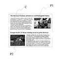
今、レイアウト対象となるひとまとまりの画像が図4に示されるように、文字列と写真からなる画像であるとする。この図4に示される画像は、新聞記事の一部を示すもので、文字列部分Cと写真P1,P2からなり、この図4に示されるレイアウトは新聞紙面専門のデザイナによってなされたものであり、多くの人が見やすく内容の理解がし易いとされるレイアウトであるとする。
【0062】
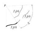
この図4に示すように、ある限られた表示範囲にレイアウトされるひとまとまりの画像全体について、上述の(1)式を用いて誘導場を計算すると、求められた誘導場によって、図5のような等ポテンシャル線Lが描かれる。なお、このようなレイアウト対象となる情報全体について誘導場を計算する際、図4で示した文字列部分Cは図5に示すように、それぞれの文字列を単純な線で表し、写真P1,P2はその外形を矩形枠で表して誘導場を計算する。
【0063】
これは、レイアウトは各要素の位置関係や大きさで決まるため、各要素を単純化して表現することができるからであり、このように、各要素を単純化して表現した状態で誘導場を計算し、求められた誘導場から等ポテンシャル線を描けば、その等ポテンシャル線はそのレイアウト全体の等ポテンシャル線を表すことができる。
【0064】
なお、図4に示すレイアウトは専門のデザイナによってデザインされた見やすく内容の理解がし易いとされるレイアウトであり、このようにレイアウトされた画像全体から得られた等ポテンシャル線Lは全体に凹凸が少なく丸みを帯びたものとなる。
【0065】
このことから、レイアウト対象となるひとまとまりの画像全体について誘導場を計算し、それによって得られた等ポテンシャル線の形状から、その画像のレイアウトの良し悪しを判断することができる。つまり、得られた等ポテンシャル線の凹凸の度合いがわかれば、それによって当該画像のレイアウトが良いレイアウトであるかどうかの評価を行うことができる。
【0066】
そこで本発明の実施の形態では、この等ポテンシャル線の凹凸の度合いを等ポテンシャル線の複雑度として求め、その複雑度を当該画像のレイアウトの良し悪しを評価する指標として用いる。つまり、等ポテンシャル線が、凹凸が少なく丸みを帯びていればいるほど複雑度は小さくなり、等ポテンシャル線の凹凸が激しいほど複雑度は大きくなる。この複雑度は、i番目の等ポテンシャル線の複雑度をCiで表せば、
Ci=Li2/Si (2)
で求めることができる。なお、(2)式において、Liはi番目の等ポテンシャル線の長さ、Siはi番目の等ポテンシャル線で囲まれた面の面積を表している。なお、 i番目の等ポテンシャル線の長さLiはそのポテンシャル線を構成するドット数と考えることができ、 i番目の等ポテンシャル線で囲まれた面の面積Siは、 i番目の等ポテンシャル線で囲まれた面に存在するドット数と考えることができる。
【0067】
この(2)式によれば、レイアウト対象となるひとまとまりの画像について計算された誘導場によって描かれた等ポテンシャル線の長さが長いほど(凹凸が激しいほど)複雑度Ciの値は大きくなるといえる。逆に言えば、等ポテンシャル線に凹凸が少なく円に近いほど複雑度Ciは小さな値となる。
【0068】
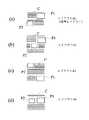
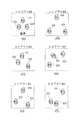
ここで、図4で示したひとまとまりの画像を図6で示すように色々なレイアウトとしたときのそれぞれの複雑度を計算してみる。この図6は図5と同様に、文字列部分Cはそれぞれの文字列を単純な線で表し、写真P1,P2は単に矩形枠で表している。
【0069】
この図6において、同図(a)は図4と同じレイアウト(これをレイアウトA1という)であり、同図(b)は図4の写真P2を文字列の中に配置したレイアウト(これをレイアウトA2という)、同図(c)は写真P1が右下、写真P2が左上となっているレイアウト(これをレイアウトA3という)、同図(d)は2つの写真P1,P2を文字列の中に配置したレイアウト(これをレイアウトA4という)である。
【0070】
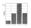
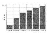
これらについて、まず、それぞれの誘導場を計算し、求められた誘導場によって描かれた等ポテンシャル線(それぞれのi番目のポテンシャル線)から、(2)式によってそれぞれ複雑度を計算すると、図7のような結果が得られた。この図7は横軸にそれぞれのレイアウトA1〜A6をとり、縦軸にそれぞれのレイアウトA1〜A6に対して求められた複雑度をとっている。
【0071】
この図7によれば、デザイナによってレイアウトされた読みやすく内容の理解のし易いとされるレイアウトA1(基準レイアウトA1という)の複雑度が最も小さく、他の3つのレイアウトA2,A3,A4はいずれも、この基準レイアウトA1に比べると、その複雑度は大きな値となっている。特に、この例においては、レイアウトA3が最も大きな複雑度となっている。
【0072】
これは、前述したように、基準レイアウトA1から求められた誘導場に凹凸が少なく全体的に丸みを帯びているためであり、他の3つのレイアウトA2〜A4はそれぞれのレイアウトから求められた等ポテンシャル線に凹凸が大きいためである。
【0073】
以上は新聞などの記事(多くは文字列と写真などからなる)の一部をレイアウト対象のひとまとまりの画像とし、そのひとまとまりの画像をレイアウトする場合についての評価を行った場合であるが、レイアウト対象の画像としては、図8に示すような一般的な画像を用いた場合の評価も同様に考えることができる。
【0074】
図8(a)〜(f)は3つの顔画像G1,G2,G3をそれぞれ異なったレイアウトB1〜B6とした例を示すもので、上述同様、これら図8(a)〜(f)のそれぞれのレイアウトB1〜B6をそれぞれひとまとまりの画像として、そのひとまとまりの画像ごとに誘導場を計算し、求められた誘導場によって描かれた等ポテンシャル線から、(2)式によってそれぞれ複雑度を計算すると、図9(a)〜(f)のような結果が得られた。なお、これらのレイアウトB1〜B6において、レイアウトB1(基準レイアウトB1という)が、多くの人が見て、座りがよく安定感のある良いレイアウトであるとされたレイアウトであるとする。
【0075】
この図9は図6同様、横軸にそれぞれのレイアウトB1〜B6をとり、縦軸にそれぞれのレイアウトB1〜B6において求められた複雑度をとっている。この図9によれば、読みやすく内容の理解のし易いとされる基準レイアウトB1の複雑度が最も小さく、他の5つのレイアウトB2〜B6はいずれも、この基準レイアウトB1に比べると、その複雑度は大きな値となっている。
【0076】
これは、前述したように、基準レイアウトB1から求められた等ポテンシャル線(図示せず)には凹凸が少なく全体的に丸みを帯びているためであり、他の5つのレイアウトはそれぞれのレイアウトから求められた等ポテンシャル線(図示せず)には凹凸が大きく複雑な形状をしているためである。
【0077】
以上のことから、レイアウトの良さと複雑度には相関があることがわかる。したがって、この複雑度を用いることで、レイアウトの良し悪しを定量的に評価できると考えられる。
【0078】
図10は本発明の画像レイアウト評価システムの概略的な構成を示す図であり、上述した誘導場を計算し、計算された誘導場から等ポテンシャル線を得て、その等ポテンシャル線の形状に基づいてレイアウトの良し悪しを定量的に評価し、それによって、最適なレイアウトはどれかを判定することを可能とするシステムである。
【0079】
この情報レイアウト評価システムは、図10からわかるように、レイアウト対象となる電子化された画像を入力するレイアウト対象画像入力手段1と、このレイアウト対象画像入力手段1に入力された画像のうち、限られた表示範囲内に表示されるレイアウト対象のひとまとまりの画像に対して視覚の誘導場を計算し、求められた視覚の誘導場から等ポテンシャル線を求める視覚の誘導場計算手段2と、この視覚の誘導場計算手段2で求められた等ポテンシャル線に基づいてレイアウトの良し悪しを評価し、どのレイアウトが最適かを判定するレイアウト評価手段3と、そのレイアウト評価手段3での処理の状況を表示可能な表示手段4とを有している。
【0080】
なお、この他に、おおまかなレイアウトの設定が可能なテンプレート5を用意しておいてもよい。このテンプレート5は、前述したようにデザイナなどが作成したテンプレートの他に、おおまかなレイアウトが行える程度のものでもよい。
【0081】
また、レイアウト評価手段3は、視覚の誘導場計算手段2で求められた等ポテンシャル線の凹凸の状況に基づいてレイアウトの良し悪しを評価し、どのレイアウトが最適かを判定する処理を行うが、その処理を行う際、この実施の形態では、上述した複雑度を用いる。
【0082】
したがって、レイアウト評価手段3は、複雑度計算手段31を備え、視覚の誘導場計算手段2で求められた等ポテンシャル線から上述の(2)式によって複雑度を計算し、その複雑度に基づいてレイアウトの良し悪しを評価し、どのレイアウトが最適かを判定する。
【0083】
このようなシステムを用いて、処理対象データの最適なレイアウトがどれかを判定する判定方法として、ここでは、2つの手法について説明する。
【0084】
その1つとして、まず、レイアウト対象となるひとまとまりの画像(文章や写真などからなる)に対し、ユーザが任意にレイアウト設定し(これを初期レイアウトという)、誘導場計算手段2によりその初期レイアウトに対して誘導場を計算し、計算された誘導場から等ポテンシャル線を得て、レイアウト評価手段3がその初期レイアウトに対する複雑度を求める処理を行う。そして、その後、その初期レイアウトからレイアウト少しづつ動かし、それぞれのレイアウトごとに、前記等ポテンシャル線をそれぞれ得る処理を行い、その中から最適なレイアウトを選択する(これを第1の手法という)。
【0085】
なお、このような処理を行う際、レイアウト対象となるひとまとまりの画像が複数種類の要素で構成される場合、それぞれの要素に対し、レイアウトを行う上で必要な特性を示す属性(このデータはタイトル、このデータは本文、このデータはどの本文とリンクしているかなどを示す情報)を記述しておき、最適なレイアウトを選択する際にその属性を参照する。
【0086】
これは、レイアウトされた内容に不具合(たとえば、始めに来るべき見出しがあとになってしまったり、その見出しに対する文章が見出しとかけ離れた位置になったり、写真とそれに関する文章がかけ離れた位置となってしまうといった不具合)が生じないような制限を設けるためであり、このような属性を参照した上で、最適なレイアウトであるか否かを判定する。
【0087】
このように、ユーザが任意に設定したレイアウトを初期レイアウトして、その初期レイアウトから少しずつレイアウトを変えて行く第1の手法は、システム側の処理は単純であるが、幾通りものレイアウトを試行錯誤的に行ってそれぞれのレイアウトについて評価を行う必要があるので、多くの時間を要する問題がある。これに対処する方法としては次のような手法(第2の手法という)がある。
【0088】
この第2の手法は、あるレイアウトを設定するためのおおまかなテンプレート5を予め用意(図10のテンプレート5)、そのテンプレートに従ったレイアウトを初期レイアウトとし、誘導場計算手段2によりその初期レイアウトに対して誘導場を計算し、計算された誘導場から等ポテンシャル線を得て、レイアウト評価手段3がその初期レイアウトに対する複雑度を求める処理を行い、その後、その初期レイアウトからレイアウト少しづつ動かし、それぞれのレイアウトごとに、前記等ポテンシャル線をそれぞれ得る処理を行い、その中から最適なレイアウトを選択するというものである。
【0089】
なお、この場合も、上述同様、レイアウト対象となるひとまとまりの画像が複数種類の要素で構成される場合、それぞれの要素に対し、レイアウトを行う上で必要な特性を示す属性を記述しておき、最適なレイアウトを選択する際にその属性を参照する。
【0090】
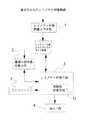
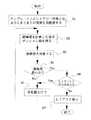
この第2の方法について、図11のフローチャートを参照しながら説明する。まず、用意されたおおまかなレイアウトの可能なテンプレート5上にレイアウト対象となるひとまとまりの画像を仮配置し(ステップs1)、その仮配置の状態で、視覚の誘導場計算手段2により誘導場を計算し、計算された誘導場から等ポテンシャル線を得て(ステップs2)、レイアウト評価手段3により複雑度を計算する(ステップs3)。そして、その複雑度が最適な値(最小の値)であるか否かを判断し(ステップs4)、最適な値(最小の値)ではないと判断したら、再配置、すなわち、初期状態から少し配置を変えたレイアウトとして(ステップs5)、ステップs2に戻り同様の処理を行う。
【0091】
このような再配置処理を何回か繰り返して行うことで、最適な値の複雑度が得られたら、そのレイアウトに不具合(上述したように、たとえば、始めに来るべき見出しがあとになってしまったり、その見出しに対する文章が見出しとかけ離れた位置になったり、写真とそれに関する文章がかけ離れた位置となってしまうといった不具合)があるか否かを判断し(ステップs6)、不具合がなければ、それを表示して(ステップs7)、処理を終了するが、レイアウトに不具合があればステップs5に戻って再レイアウトを行う。
【0092】
このように、第2の手法は、テンプレート5によって、とりあえず、おおまかなレイアウトを設定し、そのおおまかなレイアウトを基に最適なレイアウトが得られるまでレイアウトを徐々に変えて行けばよいので、最適なレイアウトが得られるまでの時間を大幅に短縮できる可能性が高くなる。
【0093】
なお、ここで用いるテンプレート5は、前述したように、非常に基本的な枠組みを表示したおおまかなテンプレートであり、例えば、それをユーザが画面上で、マウスでドラッグアンドドロップすることで、仮配置を行ってもよい。
【0094】
また、上述したように、ひとまとまりの画像を構成するそれぞれの要素に対し、レイアウトを行う上で必要な特性を示す属性(このデータはタイトル、このデータは本文、このデータはどの本文とリンクしているかなどを示す情報)を記述しておき、最適なレイアウトを選択する際にその属性を参照することが行われるが、この場合、用意するテンプレートはその属性に対応付けられたレイアウトを可能とするテンプレートとし、まずは、そのテンプレートに機械的にそれぞれの要素を当てはめ、その後、誘導場により求められる複雑度によって最適化する。
【0095】
これによって、レイアウトされた内容に上述したような不具合をなくすことができる。
【0096】
なお、本発明は以上説明した実施の形態に限定されるものではなく、本発明の要旨を逸脱しない範囲で種々変形実施可能となるものである。たとえば、上述の実施の形態では、複雑度を求める際、ある等ポテンシャル線についての複雑度を求め、その複雑度の大きさからレイアウトを評価するようにしたが、複数の等ポテンシャル線についてそれぞれの複雑度を求め、例えば、求められたそれぞれの複雑度の平均を求め、その平均の複雑度の大きさからレイアウトを評価するなど、いろいろな指標を用いることで、より良好な評価を行うことができる。
【0097】
また、前述の実施の形態では、(2)式で表される複雑度というものによって、等ポテンシャル線の凹凸の度合いを得るようにしたが、等ポテンシャル線の凹凸の度合いは、この(2)式によって表されるものではなく、他の工学的な方法によっても求めることができる。
【0098】
また、本発明は、電子データを用いた画像に対するレイアウトを行う場合に広く利用することができ、たとえば、電子化されたデータを用いた新聞などの自動配信システムにおいてレイアウトを決めるような場合や、webページのレイアウトを行う際、HTMLをベースにより一層読み易くレイアウトする場合、BSディジタル文字放送の再レイアウトを行う場合、さらには、ポスタや看板などの作成時におけるレイアウトなどにも適用することができる。
【0099】
また、本発明は、以上説明した本発明を実現するための処理手順が記述された処理プログラムを作成し、その処理プログラムをフロッピィディスク、光ディスク、ハードディスクなどの記録媒体に記録させておくことができ、本発明はその処理プログラムが記録された記録媒体をも含むものである。また、ネットワークから当該処理プログラムを得るようにしてもよい。
【0100】
【発明の効果】
以上説明したように本発明によれば、レイアウト対象となるひとまとまりの画像に対して、視覚の誘導場を計算し、求められた視覚の誘導場から等ポテンシャル線を得て、その等ポテンシャル線の形状からそのレイアウトの良し悪しを評価するようにしているので、レイアウト評価を定量的に行うことができ、それを利用することによって、人間の直感や手作業にたよっていた情報のレイアウトを自動的に最適化することが可能となる。
【0101】
また、レイアウト対象となるひとまとまりの画像が複数種類の要素で構成される場合、それぞれの要素に対し、レイアウトを行う上で必要な特性を示す属性(このデータはタイトル、このデータは本文、このデータはどの本文とリンクしているかなどを示す情報)を記述しておき、前記最適なレイアウトを選択する際にその属性を参照するようにしているので、レイアウトされた内容に不具合(たとえば、始めに来るべき見出しがあとになってしまったり、その見出しに対する文章が見出しとかけ離れた位置になったり、写真とそれに関する文章がかけ離れた位置となってしまうといった不具合)をなくすことができる。
【0102】
また、等ポテンシャル線の形状から前記レイアウトの良し悪しを評価する処理は、等ポテンシャル線の凹凸の程度を判断し、凹凸の少ない等ポテンシャル線の得られるレイアウトをよいレイアウトとしているので、レイアウト評価を定量的にかつ適正に行うことができる。なお、この等ポテンシャル線の凹凸の程度は、等ポテンシャル線の複雑度として求め、その複雑度は、当該等ポテンシャル線の長さに対する当該等ポテンシャル線で囲まれる面の面積の関係から求めるようにしているので、簡単な計算で等ポテンシャル線の凹凸の程度を判断することができ、それによって、レイアウト評価を定量的にかつ適正に行うことができる。
【図面の簡単な説明】
【図1】本発明において用いる視覚の誘導場について説明するためのディジタル画像の画素配列を示す図である。
【図2】視覚の誘導場の強さを求める際の遮蔽条件を説明する図である。
【図3】文字「A」の視覚の誘導場の例であり、同図(a)は遮蔽条件を考慮して視覚の誘導場を求めた場合、同図(b)は遮蔽条件を考慮しないで視覚の誘導場を求めた場合を示す図である。
【図4】基準となるレイアウト例としてのある新聞記事の一部分の画像を示す図である。
【図5】図4に示す画像に対し、文字列部分はそれぞれの文字列を単純な線で表し、写真は単に矩形枠で表して誘導場を計算し、計算された誘導場から得られた等ポテンシャル線を示す図である。
【図6】図4で示した基準レイアウトとその基準レイアウトを種々変化させたレイアウトとした場合の図である。
【図7】図6(a)〜(d)のようなレイアウトとしたときのそれぞれのレイアウトに対する複雑度を示す図である。
【図8】3つの顔画像をそれぞれ異なったレイアウト(6種類)とした例を示す図である。
【図9】図8(a)〜(f)のようなレイアウトとしたときのそれぞれのレイアウトに対する複雑度を示す図である。
【図10】本発明の情報のレイアウト評価システムの実施の形態を説明する概略的な構成図である。
【図11】本発明の画像レイアウト評価処理手順の実施の形態例を説明するフローチャートである。
【符号の説明】
1 レイアウト対象画像入力手段
2 視覚の誘導場計算手段
3 レイアウト評価手段
4 表示手段
5 テンプレート
31 複雑度計算手段
A1〜A4 新聞記事のレイアウト例
B1〜B6 顔画像のレイアウト例[0001]
BACKGROUND OF THE INVENTION
The present invention evaluates the layout of characters, photos, pictures, graphics, etc. (collectively these characters, photos, pictures, graphics, etc. are called images), thereby enabling layouts that are easy to see and understand the contents. The present invention relates to a layout evaluation method, an image layout evaluation system, and an image layout evaluation processing program.
[0002]
[Prior art]
When displaying images such as letters, photos, pictures, figures, etc. within a limited display range such as information equipment display screens, signboards, posters, etc., layout should be easy for many people to read and understand the contents. These layouts are traditionally often done by specialized designers.
[0003]
On the other hand, for character strings, there is a specification such as a typesetting for printing (for example, stipulation of X4051 of JIS standard), and automation is considerably advanced even if it cannot be said that it is fully automated, and a layout is appropriate. It was possible.
[0004]
[Problems to be solved by the invention]
However, it is difficult to determine the layout mechanically for not only characters but also general images including pictures, pictures, and figures, and the fact is that human intuition must be relied upon.
[0005]
In particular, the layout of an image composed of multiple types of elements such as photographs, pictures, figures, etc. in a character string is easy to read and easy to understand unless it is decided by a professional designer. Often not.
[0006]
In order to cope with this, for example, a system for automatically creating a newspaper page or the like by using digitized data is being operated.
[0007]
However, this system is a method of applying electronic data such as texts and photographs to templates (templates) that have been laid out in advance by the designer. If you try to force nonstandard data, the layout may break down. The applicable range is limited. Another problem with this system is that templates must be prepared for each application, such as newspapers for newspapers and magazines for magazines.
[0008]
In addition, since such a template is created by a designer or the like, the influence of the individual taste of the designer tends to appear, and the layout created by the template does not necessarily become a layout for everyone. .
[0009]
Therefore, the present invention enables quantitative evaluation of layout when images such as characters, photographs, pictures, figures, etc. are laid out within a limited display range. The purpose is to automatically optimize the layout of the image.
[0010]
[Means for Solving the Problems]
In order to achieve the above-described object, an image layout evaluation method according to the present invention is a layout target in the image layout evaluation method for evaluating a layout of a group of images displayed in a layout within a predetermined display range. With respect to a group of images, the group of images is set to a predetermined layout, and a visual induction field is calculated for the grouped images, and an equipotential line is calculated from the obtained visual induction field. The quality of the layout is evaluated based on the shape of the equipotential lines.
[0011]
In this image layout evaluation method, when the group of images includes characters, the character string is represented by a line, and when the group of images includes a photo, a picture, a figure, etc., The visual guidance field is calculated with an outer frame.
[0012]
In this image layout evaluation method, the process up to evaluating the quality of the layout based on the shape of the equipotential lines first takes the layout arbitrarily set by the user as the initial layout, On the other hand, the process of obtaining the equipotential line is performed, the quality of the layout is evaluated from the shape of the equipotential line, and if the layout is not the optimal layout, the layout is sequentially changed from the initial layout, respectively. The equipotential lines are obtained for each of the layouts, and the quality of the layout is evaluated from the shape of the equipotential lines, and the process may be performed until an optimal layout is obtained. .
[0013]
In this image layout evaluation method, a process for evaluating whether the layout is good or bad based on the shape of the equipotential lines is first prepared in advance as a template for setting a certain layout. The conforming layout is set as the initial layout, the equipotential line is processed for the initial layout, the quality of the layout is evaluated from the shape of the equipotential line, and the layout is not the optimal layout. The layout is changed sequentially from the initial layout, the equipotential lines are obtained for each layout, and the quality of the layout is evaluated from the shape of the equipotential lines. Until you get the right layout .
[0014]
Also, in this information layout evaluation method, when the group of images is composed of a plurality of types of elements, attributes indicating characteristics necessary for layout are described for each element, and the optimum layout is described. The attribute is referred to when a process for obtaining a simple layout is performed.
[0015]
Further, in this image layout evaluation method, when an attribute indicating characteristics necessary for layout is described for each element, the template enables a layout associated with the attribute. A template.
[0016]
Further, in this image layout evaluation method, the process for evaluating the quality of the layout from the shape of the equipotential lines is determined by determining the number of irregularities of the equipotential lines and obtaining a layout with equipotential lines with less irregularities. Is a good layout.
[0017]
Further, the number of irregularities of the equipotential line is obtained as the complexity of the equipotential line, and the complexity is obtained from the relationship of the area of the surface surrounded by the equipotential line with respect to the length of the equipotential line. I have to.
[0018]
Further, the complexity at that time is smaller as the value is smaller, and the layout that can obtain the minimum complexity is optimally laid out.
[0019]
Further, in the image layout evaluation system of the present invention, in the image layout evaluation system that performs layout evaluation of a group of images displayed in a layout within a predetermined display range, a visual image is visually displayed on the group of images to be laid out. The visual induction field calculation means for calculating the induction field of the visual field and obtaining the equipotential line from the obtained visual induction field, and the layout based on the equipotential line obtained by the visual induction field calculation means. Layout evaluation means for evaluating, and for the group of images to be laid out, the group of images is set as a predetermined layout, and a visual induction field is provided for the grouped images. The equipotential line is obtained from the calculated visual induction field and the equipotential is calculated. And so as to evaluate the right and wrong of the layout based of the shape.
[0020]
In this image layout evaluation system, the visual guidance field calculation means represents a character string by a line when the group of images includes a character, and the group of images includes a photograph, a picture, a figure, etc. Are included in the outer frame, the visual induction field is calculated.
[0021]
In this image layout evaluation system, the process up to evaluating the quality of the layout based on the shape of the equipotential lines first takes the layout arbitrarily set by the user as the initial layout. On the other hand, the visual induction field calculation means performs processing for obtaining equipotential lines, the layout evaluation means evaluates the quality of the layout based on the shape of the equipotential lines, and the layout is an optimum layout. Otherwise, the layout is sequentially changed from the initial layout, the equipotential lines are obtained for each layout, and the quality of the layout is evaluated based on the shape of the equipotential lines. You can do this until you get the best layout .
[0022]
In this image layout evaluation system, a process for evaluating the quality of the layout based on the shape of the equipotential lines first obtains a template for setting a certain layout and follows the template. The initial layout is used as an initial layout, and the visual induction field calculation means performs processing for obtaining equipotential lines for the initial layout, and the layout evaluation means determines whether the layout is good or bad based on the shape of the equipotential lines. If the layout is not the optimal layout, the layout is sequentially changed from the initial layout, the equipotential lines are obtained for each layout, and the layout is determined based on the shape of the equipotential lines. A process to evaluate good or bad, It may be carried out until the optimum layout is obtained a sense.
[0023]
Further, in this image layout evaluation system, when the group of images is composed of a plurality of types of elements, the layout evaluation means knows attributes indicating characteristics necessary for layout for each element. The attribute is referred to when the process for obtaining the optimum layout is performed.
[0024]
Further, in this image layout evaluation system, when an attribute indicating a characteristic necessary for layout is described for each element, the template enables a layout associated with the attribute. A template.
[0025]
In the image layout evaluation system, the process for evaluating the quality of the layout based on the shape of the equipotential lines performed by the layout evaluating means determines the number of irregularities of the equipotential lines and determines the equipotential with few irregularities. The layout from which lines are obtained is a good layout.
[0026]
Further, the number of irregularities of the equipotential line is obtained as the complexity of the equipotential line, and the complexity is obtained from the relationship of the area of the surface surrounded by the equipotential line with respect to the length of the equipotential line. To.
[0027]
At this time, the smaller the value of the complexity is, the smaller the complexity is, and the layout that can obtain the minimum complexity is the optimum layout.
[0028]
The image layout evaluation processing program of the present invention is an image layout evaluation processing program for performing layout evaluation of a group of images displayed in a layout within a predetermined display range, and the processing program is the layout target For a group of images, the grouped image is set to a predetermined layout, and a visual guidance field is calculated for the grouped images, and the obtained visual guidance field is used. And a procedure for obtaining equipotential lines and evaluating the quality of the layout based on the shape of the equipotential lines.
[0029]
In this image layout evaluation processing program, when the group of images includes characters, the character string is represented by a line, and when the group of images includes a photograph, a picture, a figure, etc. Is represented by an outer frame, and the visual induction field is calculated.
[0030]
In this image layout evaluation processing program, the process from the shape of the equipotential line to the evaluation of the quality of the layout is first set to the layout arbitrarily set by the user as the initial layout. The process of obtaining the equipotential lines is performed, the quality of the layout is evaluated from the shape of the equipotential lines, and if the layout is not the optimal layout, the layout is sequentially changed from the initial layout, For each layout, the equipotential lines may be obtained, and the process for evaluating the quality of the layout from the shape of the equipotential lines may be performed until an optimum layout is obtained.
[0031]
Also, in this image layout evaluation processing program, the process from the shape of the equipotential line to the evaluation of the quality of the layout is first made the layout arbitrarily set by the user as the initial layout. On the other hand, the process of obtaining the equipotential line is performed, the quality of the layout is evaluated from the shape of the equipotential line, and if the layout is not the optimal layout, the layout is sequentially changed from the initial layout, respectively. The equipotential lines are obtained for each of the layouts, and the quality of the layout is evaluated from the shape of the equipotential lines, and the process may be performed until an optimal layout is obtained. .
[0032]
Further, in the image layout evaluation processing program, when the group of images is composed of a plurality of types of elements, an attribute indicating characteristics necessary for performing layout is described for each element, The attribute is referred to when processing for obtaining the optimum layout is performed.
[0033]
Further, in this image layout evaluation processing program, when an attribute indicating a characteristic necessary for layout is described for each of the elements, the template can perform a layout associated with the attribute. Template.
[0034]
Further, in the recording medium on which the image layout evaluation processing program is recorded, the process for evaluating the quality of the layout from the shape of the equipotential lines is performed by determining the number of unevenness of the equipotential lines, and by reducing the unevenness, etc. The layout from which potential lines are obtained is a good layout.
[0035]
Further, the number of irregularities of the equipotential line is obtained as the complexity of the equipotential line, and the complexity is obtained from the relationship of the area of the surface surrounded by the equipotential line with respect to the length of the equipotential line. I have to.
[0036]
At this time, the smaller the value of the complexity is, the smaller the complexity is, and an optimal layout is obtained from which the minimum complexity can be obtained.
[0037]
As described above, in the present invention, a visual induction field is calculated for a group of images to be laid out, an equipotential line is obtained from the obtained visual induction field, and the shape of the equipotential line is obtained. Since the quality of the layout is evaluated, the layout evaluation can be performed quantitatively, and by using it, the layout based on human intuition and manual work is automatically optimized. Is possible.
[0038]
In addition, when calculating the visual induction field, the visual induction field is calculated because the character string is represented by a line and the photograph, picture, figure, etc. are represented by an outer frame to calculate the visual induction field. Can be simplified, and high-speed processing becomes possible.
[0039]
In addition, as a process from the shape of equipotential lines to evaluating the quality of the layout, the layout arbitrarily set by the user is set as the initial layout, and the layout is gradually changed from the initial layout. Obtain a equipotential line and prepare a template for evaluating the quality of the layout based on the shape of each obtained equipotential line, or a template for setting a certain layout, and follow the template A method of evaluating the quality of the layout based on the shape of each obtained equipotential line while obtaining the equipotential line in each layout while changing the layout little by little from the initial layout. There is.
[0040]
These methods can be selected depending on how much processing is left to the user side and the system side. In the former method, the operation on the system side may be simplified, although a little operation burden is imposed on the user side. On the other hand, the latter method is optimal because it is necessary to set a rough layout depending on the template and gradually change the layout until an optimal layout is obtained based on the rough layout. Therefore, there is an advantage that it is possible to greatly reduce the time until a simple layout is obtained, and the operation burden on the user can be greatly reduced. Note that the template used here does not have to be a template strictly created by a designer or the like, and may be a template that can be roughly laid out.
[0041]
In addition, when a group of images to be laid out is composed of multiple types of elements, attributes indicating the characteristics required for layout for each element (this data is the title, this data is the main text, this data Since the data describes information indicating which text is linked, and the attribute is referred to when selecting the optimum layout, there is a problem with the layout contents (for example, the beginning The problem that the headline to come to is later, the sentence for the headline is far from the headline, or the photograph and the related sentence are far from each other) can be eliminated.
[0042]
In addition, when an attribute indicating a characteristic necessary for layout is described for each element, a template used as an initial layout is a template that enables a layout associated with the attribute. Thus, it is possible to prevent the above-described problems from occurring in the layout contents.
[0043]
In addition, the process for evaluating the quality of the layout from the shape of the equipotential lines judges the number of unevenness of the equipotential lines, and the layout from which the equipotential lines with few unevenness is obtained is a good layout. Can be carried out quantitatively and appropriately.
[0044]
The number of irregularities of the equipotential line is obtained as the complexity of the equipotential line, and the complexity is obtained from the relationship of the area of the surface surrounded by the equipotential line with respect to the length of the equipotential line. Therefore, it is possible to determine the number of irregularities of the equipotential line with a simple calculation.
[0045]
The complexity is set to be smaller as the value is smaller, and the layout that can obtain the minimum complexity is optimally laid out. Therefore, appropriate layout evaluation can be performed easily.
[0046]
DETAILED DESCRIPTION OF THE INVENTION
Embodiments of the present invention will be described below. The contents described in this embodiment are descriptions of the image layout evaluation method and the image layout evaluation system of the present invention, and also include specific processing contents of the image layout evaluation processing program of the present invention.
[0047]
The present invention uses the concept of “visual guidance field” for image layout evaluation, thereby enabling an optimum layout to be determined. First, this visual guidance field will be briefly described.
[0048]
This visual guidance field is used as an index of the readability of the entire character string, for example, by evaluating the readability of individual characters existing on the character string.
[0049]
First, as an example of estimating a visual induction field of a character image based on physiological and psychological knowledge, a method of estimating a visual induction field from a digital image of a character obtained by digitization will be described.
[0050]
It should be noted that the state in which individual characters in the character string are easy to read is that the visual guidance fields surrounding the individual characters are arranged at intervals that do not interfere as much as possible. Specifically, when a closed curve of a visual induction field surrounding each character is considered, if the potential value of the closed curve is high, it is difficult to separate from other characters and difficult to read. From this, it is considered that the readability of individual characters in the character string can be quantitatively evaluated based on the spread of the visual induction field. The visual guidance field is described in Yoshimasa Yokose's “Psychology of Shape” (Nagoya University Press (1986)) (hereinafter referred to as a reference paper).
[0051]
The visual guidance field (hereinafter simply referred to as the guidance field) shown in this reference paper explains the visual phenomenon by considering the “field” that spreads around the figure. Since the reference paper is intended for figures composed of straight lines and arcs, an induction field for an arbitrary digital image is not required. Here, a method for calculating the induction field in a black and white binary digital image is shown first.
[0052]
Since the induction field can be basically interpreted as a Coulomb potential, the pixels constituting the outline of the pattern are assumed to be point charges, and the distribution of the induction field in the digital image is calculated from the accumulation of the Coulomb potential generated by them.
[0053]
FIG. 1 is a diagram showing a pixel arrangement of a digital image. As shown in FIG. 1, it is assumed that an induction field is formed at an arbitrary point P by a curve f (s) composed of n point sequences. This curve f (s) corresponds to the line segment of the line figure and the outline of the picture figure. Then, each point p1, p2,..., Pi,..., Pn constituting the curve f (s) is assumed to be a point charge having a
[0054]
[Expression 1]
[0055]
FIG. 3A shows an example of the induction field calculated by the above-described equation (1) for the letter “A”. The thin line L distributed in the contour line of the map around the letter “A” in FIG. 3A is the equipotential line of the induction field, and the intensity of the induction field becomes weaker as it goes away from the center. Get closer to.
[0056]
The feature in the shape and strength of the distribution of the induction field in FIG. 3A, in particular, the distribution near the apex of “A” is more acute than the other, the guidance related to the vicinity of the corner of the figure such as a rectangle or a triangle according to the reference paper. It agrees with the results of psychological experiments on the field distribution.
[0057]
Further, FIG. 3B shows the above-described shielding condition (the sum of the portions existing in the range Z invisible from the arbitrary point P is not taken), and the induction field assuming that all pixels are point charges of
[0058]
In this way, a guidance field for a certain character can be obtained. Examples of techniques using such a visual guidance field include, for example, “Michihiro Nagaishi:“ Easy-to-read Japanese proportional display using visual guidance field ”, Journal of the Institute of Image Media and Technology, Vol.52, No. 12, pp.1865-1872 (1998) ”(hereinafter referred to as the first paper),“ Masayoshi Miyoshi, Yoshifumi Shimoshiro, Hiroaki Koga, Takeshi Ideguchi: “Character layout based on sensibility using visual induction field theory” Design, "IEICE Transactions, 82-A, 9, 1465-1473 (1999)" (hereinafter referred to as the second paper). Incidentally, the author of the first paper mentioned above is the inventor of the present invention.
[0059]
The present invention uses such a visual induction field, and when displaying a group of images composed of characters, photographs, pictures, figures, etc. within a limited predetermined display range, the layout is optimal. The layout evaluation is performed so that the layout becomes the same, thereby automatically optimizing the layout that has previously relied on human intuition and manual work.
[0060]
In the present invention, when evaluating whether the layout is good or bad, a group of images to be laid out is regarded as one induction field calculation target, the induction field is calculated, and the shape of the equipotential line obtained thereby is calculated. Based on this, the quality of the layout is evaluated. Embodiments of the present invention will be described below.
[0061]
Now, it is assumed that a group of images to be laid out is an image composed of a character string and a photograph as shown in FIG. The image shown in FIG. 4 shows a part of a newspaper article, and is composed of a character string portion C and photographs P1 and P2, and the layout shown in FIG. 4 is made by a designer specializing in newspapers. Suppose that the layout is such that many people can easily see and understand the contents.
[0062]
As shown in FIG. 4, when the induction field is calculated using the above-described equation (1) for the entire group of images laid out in a limited display range, the obtained induction field determines that the induction field shown in FIG. Such an equipotential line L is drawn. When the guidance field is calculated for the entire information to be laid out, the character string portion C shown in FIG. 4 represents each character string as a simple line as shown in FIG. P2 calculates the induction field by representing the outer shape with a rectangular frame.
[0063]
This is because the layout is determined by the positional relationship and size of each element, so each element can be expressed in a simplified manner. In this way, the induction field is calculated with each element expressed in a simplified manner. If an equipotential line is drawn from the obtained induction field, the equipotential line can represent the equipotential line of the entire layout.
[0064]
The layout shown in FIG. 4 is a layout designed by a professional designer that is easy to see and understand the contents, and the equipotential lines L obtained from the entire image thus laid out are uneven. Less rounded.
[0065]
From this, it is possible to calculate the induction field for the entire group of images to be laid out, and to judge the quality of the layout of the image from the shape of the equipotential lines obtained thereby. That is, if the degree of unevenness of the obtained equipotential lines is known, it can be evaluated whether the layout of the image is a good layout.
[0066]
Therefore, in the embodiment of the present invention, the degree of unevenness of the equipotential line is obtained as the complexity of the equipotential line, and the complexity is used as an index for evaluating the quality of the layout of the image. In other words, the more the equipotential line is rounded with less unevenness, the smaller the complexity, and the more the equipotential line is uneven, the greater the complexity. This complexity is expressed as Ci if the complexity of the i-th equipotential line is expressed as
Ci = Li2 / Si (2)
Can be obtained. In equation (2), Li represents the length of the i-th equipotential line, and Si represents the area of the surface surrounded by the i-th equipotential line. Note that the length Li of the i-th equipotential line can be considered as the number of dots constituting the potential line, and the area Si of the surface surrounded by the i-th equipotential line is the i-th equipotential line. It can be considered as the number of dots existing on the enclosed surface.
[0067]
According to the equation (2), when the length of the equipotential line drawn by the induction field calculated for the group of images to be laid out is longer (the unevenness is more severe), the value of the complexity Ci increases. I can say that. In other words, the complexity Ci becomes smaller as the equipotential line is less uneven and closer to a circle.
[0068]
Now, let us calculate the complexity of the group of images shown in FIG. 4 when they are arranged in various layouts as shown in FIG. In FIG. 6, as in FIG. 5, the character string portion C represents each character string by a simple line, and the photographs P1 and P2 are simply represented by a rectangular frame.
[0069]
6A is the same layout (referred to as layout A1) as in FIG. 4, and FIG. 6B is a layout in which the photo P2 in FIG. 4 is arranged in a character string (this is the layout). (C2) is a layout in which the photo P1 is in the lower right and the photo P2 is in the upper left (this is called layout A3), and (d) in the figure shows the two photos P1 and P2 in the character string. (This is called layout A4).
[0070]
For each of these, first, the respective induction fields are calculated, and from the equipotential lines (each i-th potential line) drawn by the obtained induction fields, the complexity is calculated according to the equation (2). The following results were obtained. In FIG. 7, the horizontal axis represents the respective layouts A1 to A6, and the vertical axis represents the complexity obtained for each of the layouts A1 to A6.
[0071]
According to FIG. 7, the layout A1 (referred to as the reference layout A1), which is easy to read and understand the content laid out by the designer, has the smallest complexity, and the other three layouts A2, A3, A4 However, the complexity is larger than that of the reference layout A1. In particular, in this example, the layout A3 has the greatest complexity.
[0072]
This is because, as described above, the induction field obtained from the reference layout A1 has less unevenness and is generally rounded, and the other three layouts A2 to A4 are obtained from the respective layouts, etc. This is because the potential line has large irregularities.
[0073]
The above is a case where a part of an article such as a newspaper (mostly composed of character strings and photos) is regarded as a group of images to be laid out, and the case of evaluating the group of images is evaluated. As a layout target image, an evaluation using a general image as shown in FIG. 8 can be similarly considered.
[0074]
FIGS. 8A to 8F show examples in which the three face images G1, G2, and G3 have different layouts B1 to B6. Similarly to the above, these FIGS. 8A to 8F respectively. Each of the layouts B1 to B6 is a group of images, the induction field is calculated for each group of images, and the complexity is calculated by the formula (2) from the equipotential lines drawn by the obtained induction field. Then, the results as shown in FIGS. 9A to 9F were obtained. In these layouts B1 to B6, it is assumed that the layout B1 (referred to as the reference layout B1) is a layout that is considered to be a good layout that is satisfactorily seated and stable.
[0075]
In FIG. 9, as in FIG. 6, the horizontal axis represents the respective layouts B1 to B6, and the vertical axis represents the complexity obtained in the respective layouts B1 to B6. According to FIG. 9, the complexity of the reference layout B1 that is easy to read and easy to understand the content is the smallest, and the other five layouts B2 to B6 are all more complex than the reference layout B1. The degree is a big value.
[0076]
This is because, as described above, the equipotential lines (not shown) obtained from the reference layout B1 have less unevenness and are rounded as a whole, and the other five layouts are derived from the respective layouts. This is because the obtained equipotential lines (not shown) have large irregularities and a complicated shape.
[0077]
From the above, it can be seen that there is a correlation between good layout and complexity. Therefore, it is considered that the quality of the layout can be quantitatively evaluated by using this complexity.
[0078]
FIG. 10 is a diagram showing a schematic configuration of the image layout evaluation system of the present invention. The above induction field is calculated, an equipotential line is obtained from the calculated induction field, and the shape of the equipotential line is calculated. Thus, the system can quantitatively evaluate the quality of the layout, and thereby determine which layout is optimal.
[0079]
As can be seen from FIG. 10, the information layout evaluation system includes a layout target
[0080]
In addition, a
[0081]
The layout evaluation means 3 evaluates the quality of the layout based on the unevenness of the equipotential lines obtained by the visual guidance field calculation means 2 and determines which layout is optimal. In performing this processing, the complexity described above is used in this embodiment.
[0082]
Therefore, the
[0083]
Here, two methods will be described as a determination method for determining which layout is optimal for the processing target data using such a system.
[0084]
As one of them, first, the user arbitrarily sets a layout for a group of images (including texts and photographs) to be laid out (this is called an initial layout), and the initial layout is calculated by the guidance field calculation means 2. The induction field is calculated with respect to, an equipotential line is obtained from the calculated induction field, and the layout evaluation means 3 performs processing for obtaining the complexity for the initial layout. Thereafter, the layout is moved little by little from the initial layout, and the process of obtaining the equipotential lines is performed for each layout, and the optimum layout is selected from these (this is called the first method).
[0085]
When such a process is performed, if a group of images to be laid out is composed of a plurality of types of elements, attributes indicating the characteristics necessary for layout for each element (this data is The title, the text is the text, and information indicating which text is linked to the text) are described, and the attributes are referred to when the optimum layout is selected.
[0086]
This can be a problem with the layout (for example, the headline to come first is after, the text for the heading is far from the heading, or the photo and the text about it are far from each other). In view of such attributes, it is determined whether or not the layout is optimal.
[0087]
In this way, the first method of initial layout of the layout arbitrarily set by the user and changing the layout little by little from the initial layout is simple on the system side, but various layouts are tried. Since it is necessary to make an error and evaluate each layout, there is a problem that takes a lot of time. As a method for dealing with this, there is the following method (referred to as a second method).
[0088]
In this second method, a
[0089]
In this case as well, as described above, when a group of images to be laid out is composed of a plurality of types of elements, an attribute indicating characteristics necessary for layout is described for each element. , Refer to its attributes when selecting the optimal layout.
[0090]
The second method will be described with reference to the flowchart of FIG. First, a group of images to be laid out is provisionally arranged on the
[0091]
By repeating this relocation process several times, if the optimal value complexity is obtained, the layout may be faulty (for example, the headline to come first is Whether or not there is a problem that the sentence for the headline is far from the headline or the photograph and the related sentence are far from each other (step s6). This is displayed (step s7), and the process is terminated. If there is a defect in the layout, the process returns to step s5 to perform the layout again.
[0092]
In this way, the second method is to set the rough layout for the time being using the
[0093]
Note that the
[0094]
In addition, as described above, for each element constituting a group of images, attributes indicating characteristics necessary for layout (this data is a title, this data is a text, this data is linked to which text) Information), and the attribute is referred to when selecting the optimal layout. In this case, the template to be prepared can have a layout associated with the attribute. First, each element is mechanically applied to the template, and then optimized according to the complexity required by the induction field.
[0095]
As a result, the above-described problems can be eliminated from the layout contents.
[0096]
The present invention is not limited to the embodiment described above, and various modifications can be made without departing from the gist of the present invention. For example, in the above-described embodiment, when obtaining the complexity, the complexity for a certain equipotential line is obtained, and the layout is evaluated from the magnitude of the complexity. It is possible to perform a better evaluation by using various indices such as calculating the complexity, for example, calculating the average of each calculated complexity, and evaluating the layout from the average complexity. it can.
[0097]
In the above-described embodiment, the degree of unevenness of the equipotential line is obtained according to the complexity expressed by the equation (2). It is not expressed by an equation, but can be obtained by other engineering methods.
[0098]
In addition, the present invention can be widely used when laying out an image using electronic data, for example, in a case where a layout is determined in an automatic distribution system such as a newspaper using digitized data, When laying out a web page, it can be applied to a more easily readable layout based on HTML, to a re-layout of BS digital teletext, and also to a layout when creating posters, signs, etc. .
[0099]
In addition, the present invention can create a processing program in which the processing procedure for realizing the present invention described above is described, and the processing program can be recorded on a recording medium such as a floppy disk, an optical disk, or a hard disk. The present invention also includes a recording medium on which the processing program is recorded. Further, the processing program may be obtained from a network.
[0100]
【The invention's effect】
As described above, according to the present invention, a visual induction field is calculated for a group of images to be laid out, an equipotential line is obtained from the obtained visual induction field, and the equipotential line is obtained. Since the layout is evaluated based on the shape of the layout, it is possible to quantitatively evaluate the layout, and by using this, the layout of information based on human intuition and manual work is automatically performed. Can be optimized.
[0101]
In addition, when a group of images to be laid out is composed of multiple types of elements, attributes indicating the characteristics required for layout for each element (this data is the title, this data is the main text, this data Since the data describes information indicating which text is linked, and the attribute is referred to when selecting the optimum layout, there is a problem with the layout contents (for example, the beginning The problem that the headline to come to is later, the sentence for the headline is far from the headline, or the photograph and the related sentence are far from each other) can be eliminated.
[0102]
In addition, the process for evaluating the quality of the layout based on the shape of the equipotential line judges the degree of unevenness of the equipotential line, and the layout from which the equipotential line with few unevenness is obtained is a good layout. It can be done quantitatively and appropriately. The degree of unevenness of the equipotential line is obtained as the complexity of the equipotential line, and the complexity is obtained from the relationship of the area of the surface surrounded by the equipotential line with respect to the length of the equipotential line. Therefore, it is possible to determine the degree of unevenness of the equipotential line by simple calculation, and thereby layout evaluation can be performed quantitatively and appropriately.
[Brief description of the drawings]
FIG. 1 is a diagram showing a pixel arrangement of a digital image for explaining a visual induction field used in the present invention.
FIG. 2 is a diagram for explaining a shielding condition when obtaining the strength of a visual induction field.
FIG. 3 is an example of a visual guidance field for the letter “A”. FIG. 3A shows a visual guidance field in consideration of the shielding condition, and FIG. 3B does not consider the shielding condition. It is a figure which shows the case where the visual induction field is calculated | required by.
FIG. 4 is a diagram showing an image of a part of a certain newspaper article as a reference layout example;
FIG. 5 is obtained from the calculated induction field by calculating the induction field with the character string portion representing each character string as a simple line with respect to the image shown in FIG. It is a figure which shows an equipotential line.
6 is a diagram in the case where the reference layout shown in FIG. 4 and a layout in which the reference layout is variously changed are used. FIG.
FIG. 7 is a diagram showing the complexity of each layout when the layouts shown in FIGS.
FIG. 8 is a diagram illustrating an example in which three face images have different layouts (six types).
FIG. 9 is a diagram showing the complexity of each layout when the layouts are as shown in FIGS.
FIG. 10 is a schematic configuration diagram illustrating an embodiment of an information layout evaluation system according to the present invention.
FIG. 11 is a flowchart illustrating an embodiment of an image layout evaluation processing procedure according to the present invention.
[Explanation of symbols]
1 Layout target image input means
2 Visual guidance field calculation means
3 Layout evaluation means
4 display means
5 Template
31 Complexity calculation means
A1-A4 Newspaper article layout example
B1-B6 face image layout example
Claims (12)
Translated fromJapanese前記コンピュータが、前記視覚の誘導場計算工程で求められた等ポテンシャル線に基づいてレイアウトを評価するレイアウト評価工程と、を有し、前記レイアウト評価工程は、前記等ポテンシャル線の凹凸の数を取得し、凹凸の数の少ない等ポテンシャル線の得られるレイアウトを表示レイアウトであるとし、前記レイアウト評価工程における前記等ポテンシャル線の凹凸の数は、等ポテンシャル線の複雑度とし、前記複雑度は、前記等ポテンシャル線の長さに対する前記等ポテンシャル線で囲まれる面の面積の関係から求め、求められた前記複雑度のうちの最小値を前記凹凸の数の少ない等ポテンシャル線の得られるレイアウトとすることを特徴とする画像レイアウト評価方法。In an image layout evaluation method for evaluating a layout of an image displayed in a layout withina predetermined display rangeusing a computer, the computercalculates a visual induction field for the image to be laid out, and is calculated A visual induction field calculation step for obtaining an equipotential line from the visual induction field;
A layout evaluation step in which the computer evaluates a layout based on an equipotential line obtained in the visual induction field calculation step, and the layout evaluation step acquires the number of irregularities of the equipotential line. And the layout from which equipotential lines with a small number of irregularities are obtained is a display layout, the number of irregularities of the equipotential lines in the layout evaluation step is the complexity of equipotential lines, and the complexity is Obtain from the relationship between the area of the surface surrounded by the equipotential line with respect to the length of the equipotential line, and make the minimum value of the obtained complexity the layout from which the equipotential line with a small number of irregularities can be obtained. An image layout evaluation method characterized by the above.
Priority Applications (2)
| Application Number | Priority Date | Filing Date | Title |
|---|---|---|---|
| JP2001213424AJP4165042B2 (en) | 2001-07-13 | 2001-07-13 | Image layout evaluation method, image layout evaluation system, and image layout evaluation processing program |
| US10/192,640US7046849B2 (en) | 2001-07-13 | 2002-07-11 | Image-layout evaluation method, image-layout evaluation system, and image-layout-evaluation-processing program |
Applications Claiming Priority (1)
| Application Number | Priority Date | Filing Date | Title |
|---|---|---|---|
| JP2001213424AJP4165042B2 (en) | 2001-07-13 | 2001-07-13 | Image layout evaluation method, image layout evaluation system, and image layout evaluation processing program |
Publications (2)
| Publication Number | Publication Date |
|---|---|
| JP2003030673A JP2003030673A (en) | 2003-01-31 |
| JP4165042B2true JP4165042B2 (en) | 2008-10-15 |
Family
ID=19048404
Family Applications (1)
| Application Number | Title | Priority Date | Filing Date |
|---|---|---|---|
| JP2001213424AExpired - Fee RelatedJP4165042B2 (en) | 2001-07-13 | 2001-07-13 | Image layout evaluation method, image layout evaluation system, and image layout evaluation processing program |
Country Status (2)
| Country | Link |
|---|---|
| US (1) | US7046849B2 (en) |
| JP (1) | JP4165042B2 (en) |
Families Citing this family (24)
| Publication number | Priority date | Publication date | Assignee | Title |
|---|---|---|---|---|
| JP4147754B2 (en)* | 2001-07-13 | 2008-09-10 | セイコーエプソン株式会社 | Image evaluation method, image evaluation system, and image evaluation processing program |
| JP4082591B2 (en)* | 2003-05-20 | 2008-04-30 | インターナショナル・ビジネス・マシーンズ・コーポレーション | Data editing apparatus and program |
| US7260276B2 (en)* | 2004-06-30 | 2007-08-21 | Sharp Laboratories Of America, Inc. | Methods and systems for complexity estimation and complexity-based selection |
| JP4047326B2 (en) | 2004-11-25 | 2008-02-13 | キヤノン株式会社 | Layout device, layout method, and program |
| JP4789589B2 (en)* | 2005-11-11 | 2011-10-12 | キヤノン株式会社 | Layout method and apparatus |
| JP4827498B2 (en)* | 2005-11-11 | 2011-11-30 | キヤノン株式会社 | Layout method and apparatus |
| US7602157B2 (en)* | 2005-12-28 | 2009-10-13 | Flyback Energy, Inc. | Supply architecture for inductive loads |
| FR2897183A1 (en)* | 2006-02-03 | 2007-08-10 | Thomson Licensing Sas | METHOD FOR VERIFYING THE SAVING AREAS OF A MULTIMEDIA DOCUMENT, METHOD FOR CREATING AN ADVERTISING DOCUMENT, AND COMPUTER PROGRAM PRODUCT |
| JP5539879B2 (en)* | 2007-09-18 | 2014-07-02 | フライバック エネルギー,インク. | Current waveform structure that generates AC power with low harmonic distortion from a local energy source |
| US8042039B2 (en)* | 2008-05-25 | 2011-10-18 | Hewlett-Packard Development Company, L.P. | Populating a dynamic page template with digital content objects according to constraints specified in the dynamic page template |
| JP4893796B2 (en)* | 2009-10-06 | 2012-03-07 | セイコーエプソン株式会社 | Device for determining readability of character strings |
| JP4893795B2 (en)* | 2009-10-06 | 2012-03-07 | セイコーエプソン株式会社 | Judgment method and apparatus for readability of character string |
| US8860273B2 (en)* | 2009-12-28 | 2014-10-14 | Flyback Energy, Inc. | External field interaction motor |
| JP2013516156A (en)* | 2009-12-28 | 2013-05-09 | フライバック エネルギー,インク. | Controllable general-purpose power supply for managing reactive power |
| GB2491872B (en)* | 2011-06-16 | 2017-12-13 | Starleaf Ltd | Video conferencing systems |
| JP5942686B2 (en)* | 2011-09-08 | 2016-06-29 | 株式会社デンソー | Display control device |
| WO2013021654A1 (en) | 2011-08-11 | 2013-02-14 | 株式会社デンソー | Display control device |
| JP5505482B2 (en) | 2011-10-24 | 2014-05-28 | 株式会社デンソー | Display control device |
| JP5454654B1 (en) | 2011-10-24 | 2014-03-26 | 株式会社デンソー | Display control apparatus and display image allocation method |
| JP5796566B2 (en) | 2011-12-28 | 2015-10-21 | 株式会社デンソー | Display control device |
| WO2013112065A1 (en)* | 2012-01-25 | 2013-08-01 | Intel Corporation | Object selection in an image |
| JP5813562B2 (en)* | 2012-04-16 | 2015-11-17 | 株式会社豊田中央研究所 | Operation support apparatus, operation system, operation support method, and program |
| JP6045232B2 (en) | 2012-07-09 | 2016-12-14 | キヤノン株式会社 | Image processing apparatus, image processing method, and program |
| CN104584081B (en)* | 2012-09-03 | 2018-04-27 | 索尼公司 | Information processing device, information processing method and program |
Family Cites Families (6)
| Publication number | Priority date | Publication date | Assignee | Title |
|---|---|---|---|---|
| JPH07117986B2 (en)* | 1992-11-18 | 1995-12-18 | 株式会社エイ・ティ・アール視聴覚機構研究所 | Character recognition device |
| US6330358B1 (en)* | 1993-01-14 | 2001-12-11 | Atr Auditory And Visual Perception Research Laboratories | Apparatus for character segmentation and apparatus for character recognition using the same |
| US6687404B1 (en)* | 1997-06-20 | 2004-02-03 | Xerox Corporation | Automatic training of layout parameters in a 2D image model |
| AUPQ027899A0 (en)* | 1999-05-10 | 1999-06-03 | Canon Information Systems Research Australia Pty Ltd | Method and apparatus for automatically positioning one or more objects within a region |
| JP4147754B2 (en)* | 2001-07-13 | 2008-09-10 | セイコーエプソン株式会社 | Image evaluation method, image evaluation system, and image evaluation processing program |
| US7308650B2 (en)* | 2003-08-29 | 2007-12-11 | Seiko Epson Corporation | Image layout device |
- 2001
- 2001-07-13JPJP2001213424Apatent/JP4165042B2/ennot_activeExpired - Fee Related
- 2002
- 2002-07-11USUS10/192,640patent/US7046849B2/ennot_activeExpired - Fee Related
Also Published As
| Publication number | Publication date |
|---|---|
| US20030086619A1 (en) | 2003-05-08 |
| JP2003030673A (en) | 2003-01-31 |
| US7046849B2 (en) | 2006-05-16 |
Similar Documents
| Publication | Publication Date | Title |
|---|---|---|
| JP4165042B2 (en) | Image layout evaluation method, image layout evaluation system, and image layout evaluation processing program | |
| JP5465015B2 (en) | Apparatus and method for digitizing documents | |
| JP5274495B2 (en) | How to change the document image size | |
| JP4321549B2 (en) | Document creation system, document creation method, program, and storage medium | |
| US7272785B2 (en) | Data editing for improving readability of a display | |
| JP4572669B2 (en) | Layout rule generation system, layout system, layout rule generation method, and layout rule generation program | |
| US8000529B2 (en) | System and method for creating an editable template from a document image | |
| EP3462333B1 (en) | Method for emphasizing differences in graphical appearance between an original document and a modified document with annotations | |
| JP4029636B2 (en) | Object layout device, image layout device, object layout program, image layout program, object layout method, and image layout method | |
| US20100153834A1 (en) | Business form creating system, network system using the same, and business form creating method | |
| JP3943638B2 (en) | Automatic recognition method of drop word in document image without using OCR | |
| US20040165000A1 (en) | Picture layout processing apparatus, picture layout processing method, and program therefor | |
| JP2015170982A (en) | Image processor | |
| JP4147754B2 (en) | Image evaluation method, image evaluation system, and image evaluation processing program | |
| JP2004280597A (en) | Layout evaluation system, layout evaluation program, and layout evaluation method | |
| JPH0612540B2 (en) | Document creation support device | |
| JP4211338B2 (en) | Image layout apparatus, image layout program, and image layout method | |
| JP3544324B2 (en) | CHARACTER STRING INFORMATION EXTRACTION DEVICE AND METHOD, AND RECORDING MEDIUM CONTAINING THE METHOD | |
| JP2003150289A (en) | Image display method, image display system, and image display processing program | |
| JP2003150959A (en) | Image evaluation method, image evaluation system, and image evaluation processing program | |
| JPH11175519A (en) | Method for analyzing document and device therefor | |
| JP2003150580A (en) | Image layout evaluation method, image layout evaluation system, and image layout evaluation processing program | |
| JP3787390B2 (en) | Character data creation device and character data creation method | |
| JP2003256467A (en) | Image selection device, image selection program, and image selection method | |
| JP2004171115A (en) | Image evaluation method and image evaluation device |
Legal Events
| Date | Code | Title | Description |
|---|---|---|---|
| A621 | Written request for application examination | Free format text:JAPANESE INTERMEDIATE CODE: A621 Effective date:20050614 | |
| RD04 | Notification of resignation of power of attorney | Free format text:JAPANESE INTERMEDIATE CODE: A7424 Effective date:20070402 | |
| A977 | Report on retrieval | Free format text:JAPANESE INTERMEDIATE CODE: A971007 Effective date:20080207 | |
| A131 | Notification of reasons for refusal | Free format text:JAPANESE INTERMEDIATE CODE: A131 Effective date:20080226 | |
| A521 | Written amendment | Free format text:JAPANESE INTERMEDIATE CODE: A523 Effective date:20080424 | |
| TRDD | Decision of grant or rejection written | ||
| A01 | Written decision to grant a patent or to grant a registration (utility model) | Free format text:JAPANESE INTERMEDIATE CODE: A01 Effective date:20080708 | |
| A01 | Written decision to grant a patent or to grant a registration (utility model) | Free format text:JAPANESE INTERMEDIATE CODE: A01 | |
| A61 | First payment of annual fees (during grant procedure) | Free format text:JAPANESE INTERMEDIATE CODE: A61 Effective date:20080721 | |
| R150 | Certificate of patent or registration of utility model | Free format text:JAPANESE INTERMEDIATE CODE: R150 | |
| FPAY | Renewal fee payment (event date is renewal date of database) | Free format text:PAYMENT UNTIL: 20110808 Year of fee payment:3 | |
| FPAY | Renewal fee payment (event date is renewal date of database) | Free format text:PAYMENT UNTIL: 20120808 Year of fee payment:4 | |
| LAPS | Cancellation because of no payment of annual fees |