JP4163942B2 - Wireless communication apparatus and wireless transmission method - Google Patents
Wireless communication apparatus and wireless transmission methodDownload PDFInfo
- Publication number
- JP4163942B2 JP4163942B2JP2002375265AJP2002375265AJP4163942B2JP 4163942 B2JP4163942 B2JP 4163942B2JP 2002375265 AJP2002375265 AJP 2002375265AJP 2002375265 AJP2002375265 AJP 2002375265AJP 4163942 B2JP4163942 B2JP 4163942B2
- Authority
- JP
- Japan
- Prior art keywords
- signal
- subcarrier
- unit
- transmission
- weighting
- Prior art date
- Legal status (The legal status is an assumption and is not a legal conclusion. Google has not performed a legal analysis and makes no representation as to the accuracy of the status listed.)
- Expired - Lifetime
Links
Images


Classifications
- H—ELECTRICITY
- H04—ELECTRIC COMMUNICATION TECHNIQUE
- H04L—TRANSMISSION OF DIGITAL INFORMATION, e.g. TELEGRAPHIC COMMUNICATION
- H04L5/00—Arrangements affording multiple use of the transmission path
- H04L5/0001—Arrangements for dividing the transmission path
- H04L5/0014—Three-dimensional division
- H04L5/0016—Time-frequency-code
- H04L5/0021—Time-frequency-code in which codes are applied as a frequency-domain sequences, e.g. MC-CDMA
- H—ELECTRICITY
- H04—ELECTRIC COMMUNICATION TECHNIQUE
- H04L—TRANSMISSION OF DIGITAL INFORMATION, e.g. TELEGRAPHIC COMMUNICATION
- H04L25/00—Baseband systems
- H04L25/02—Details ; arrangements for supplying electrical power along data transmission lines
- H04L25/03—Shaping networks in transmitter or receiver, e.g. adaptive shaping networks
- H04L25/03006—Arrangements for removing intersymbol interference
- H04L25/03343—Arrangements at the transmitter end
- H—ELECTRICITY
- H04—ELECTRIC COMMUNICATION TECHNIQUE
- H04L—TRANSMISSION OF DIGITAL INFORMATION, e.g. TELEGRAPHIC COMMUNICATION
- H04L5/00—Arrangements affording multiple use of the transmission path
- H04L5/0001—Arrangements for dividing the transmission path
- H04L5/0014—Three-dimensional division
- H04L5/0016—Time-frequency-code
- H04L5/0017—Time-frequency-code in which a distinct code is applied, as a temporal sequence, to each frequency
Landscapes
- Engineering & Computer Science (AREA)
- Signal Processing (AREA)
- Computer Networks & Wireless Communication (AREA)
- Mobile Radio Communication Systems (AREA)
Description
Translated fromJapanese【0001】
【発明の属する技術分野】
本発明は、マルチキャリア伝送方式の無線通信装置及び無線送信方法に関する。
【0002】
【従来の技術】
従来、マルチキャリアCDMA(Code Division Multiple Access)システムでは、送信装置において、送信データを周波数軸方法に拡散し、コード多重してデータを送信するようになされている。送信されたデータは、周波数選択性フェージングの影響を受けて受信装置に受信されることにより、受信装置において、拡散コード間の直交性の崩れが発生し、受信性能が劣化する。拡散コード間の直交性の崩れを低減して受信性能を向上させるために、MMSE(Minimum Mean Square Error)等のアルゴリズムを適用した逆拡散を行って受信性能を向上させる方法が広く知られている(例えば非特許文献1参照)。
【0003】
また、受信装置において、各サブキャリアの電力を等しくすれば、受信装置において拡散コード間の直交性の崩れがなくなることにより、受信装置において各サブキャリアの受信電力が等しくなるよう、予め送信装置においてサブキャリアの送信パワーを調整して送信する方法が考えられている(非特許文献2参照)。
【0004】
【非特許文献1】
「SIR推定に基づくMMSE合成を用いた下りリンクブロードバンドOFCDMパケット伝送の特性,電子情報通信学会技術報告 無線通信システム研究会 RCS2001-166 2001年10月」
【非特許文献2】
「Performance of predistortion techniques for uplink MC-CDMA systems with TDD and FDD modes, 国際学会 The Fifth International Symposium on Wireless Personal Multimedia Communications (WPMC'02) 2002年10月」
【0005】
【発明が解決しようとする課題】
しかしながら、非特許文献1に示されるMMSEのアルゴリズムを適用した受信方法では、受信装置において、ノイズの電力の測定が必要であることにより、受信装置の構成が複雑になる。また、伝搬環境の状態によっては、拡散コード間の直交性の崩れを完全に回復することは困難であることにより、必ずしも最適な受信性能を得ることはできないという問題があった。
【0006】
また、非特許文献2に示される方法では、受信装置においてEGC(等利得)合成を行うようになされていることにより、MRC合成を行う場合に比べて受信性能が劣化するという問題があった。
【0007】
図6は従来の送信装置10の構成を示すブロック図である。送信装置10において、コード多重数(受信装置数)だけ設けられた拡散部11及びシリアル/パラレル(S/P)変換部12に各受信装置への送信データがそれぞれ入力される。
【0008】
拡散部11は、送信データを所定の拡散コードを用いて拡散処理した後、拡散後の信号をS/P変換部12に供給する。S/P変換部12は、拡散後のシリアル信号をパラレル信号に変換することにより、例えば4つのサブキャリアを生成し、これをそれぞれ対応する加算器13−1〜13−4に供給する。
【0009】
加算器13−1は、コード多重数(受信装置数)分だけ設けられている拡散部11及びS/P変換部12の組み合わせのうちの第1の組から出力される第1のサブキャリアと、拡散部11及びS/P変換部12の組み合わせのうちの第2の組から出力される第1のサブキャリアとを加算する。これにより、第1のサブキャリアには、第1のユーザ(受信装置)宛に第1の拡散コードによって拡散された信号と、第2のユーザ(受信装置)宛に第2の拡散コードによって拡散された信号とが加算され、第1のサブキャリアを構成する。この第1のサブキャリアは乗算器14−1に供給される。
【0010】
また、他の加算器13−2〜13−4も同様にして、各ユーザ(受信装置)ごとに対応した拡散部11及びS/P変換部12の各組から出力される第2のサブキャリア同士、第3のサブキャリア同士、第4のサブキャリア同士をそれぞれ加算し、その結果を乗算器14−2〜14−4に供給する。乗算器14−1〜14−4は、それぞれ、重み係数算出部23において各サブキャリアに対応して算出された重み係数を各サブキャリアに乗算する。
【0011】
乗算器14−1〜14−4の出力はIFFT(Inverse Fast Fourier Transform)処理部15に供給される。IFFT処理部15は、各サブキャリアを重畳することにより、OFDM信号(マルチキャリア信号)を生成し、これをGI(Gird Interval)付加部16に供給する。GI付加部16は、OFDM信号に対してガードインターバルを付加した後、送信RF(Radio Frequency)部17に供給する。送信RF部17は、ガードインターバル挿入後の信号に対して所定の無線送信処理(例えば、D/A変換やアップコンバードなど)を行い、この無線送信処理後の信号を無線信号としてアンテナ18を介して送信する。
【0012】
送信装置10から送信された信号は、受信装置において受信される。図7は受信装置30の構成を示すブロック図である。受信装置30において、アンテナ31を介して受信RF部32に受信された受信信号は、ここで所定の無線受信処理(例えば、ダウンコンバートやA/D変換など)が施される。受信RF部32は、この無線受信処理後の信号を、GI除去部33に供給する。
【0013】
GI除去部33では、無線受信処理後の信号に挿入されているガードインターバルを除去し、このガードインターバル除去後の信号をFFT(Fast Fourier Transform)処理部34に供給する。FFT処理部34は、ガードインターバル除去後の信号に対して、シリアル/パラレル(S/P)変換し、S/P変換後の信号にFFT処理を行ってサブキャリアごとの情報に変換し、このFFT処理後の信号のうち既知信号であるパイロットシンボルを、サブキャリアごとにチャネル推定部35に供給する。
【0014】
チャネル推定部35は、サブキャリアごとのパイロットシンボルを用いてサブキャリアごとにチャネル推定を行い、得られたサブキャリアごとのチャネル推定値をEGC係数算出部36及び制御チャネル送信部39にそれぞれ供給する。
【0015】
EGC(Equal Gain Combining)係数算出部36では、サブキャリアごとのチャネル推定値に対して等利得合成を行うためのEGC係数を算出し、このEGC係数を乗算器37−1〜37−4に供給する。乗算器37−1〜37−4は、FFT処理部34から出力されたFFT処理後の各サブキャリアに対して、EGC係数算出部36から供給される係数を乗算し、その乗算結果を逆拡散部38に供給することにより、ECG逆拡散処理を行う。
【0016】
また、制御チャネル送信部39は、チャネル推定部35から供給された各サブキャリアのチャネル推定値を制御チャネルで送信するためのものであり、各チャネル推定値を送信RF部40に供給する。送信RF部40は、各チャネル推定値情報に対して所定の無線送信処理(例えば、D/A変換やアップコンバードなど)を行い、この無線送信処理後の信号を無線信号としてアンテナ41を介して送信する。
【0017】
この受信装置30から送信された信号を受信した送信装置10(図6)では、その受信RF部20において、その受信信号に対して所定の無線受信処理(例えば、ダウンコンバートやA/D変換など)を行い、この無線受信処理後の信号を、制御チャネル受信部21に供給する。制御チャネル受信部21は、受信信号から制御チャネルを抽出し、この抽出された制御チャネルのデータをチャネル情報検出部22に供給する。
【0018】
チャネル情報検出部22は、制御チャネルによって受信装置からフィードバック情報として送信された各サブキャリアごとのチャネル推定値を検出し、このチャネル推定値を重み係数算出部23に供給する。重み係数算出部23は、各サブキャリアごとにチャネル推定値から重み係数を算出し、算出された重み係数を乗算器14−1〜14−4に供給する。この重み係数として、例えば、図8に示すように、各サブキャリアごとにチャネル推定値の逆数を用いるようにしている。これにより、受信装置30における受信電力が小さなサブキャリアは送信装置10において送信電力を大きくして送信し、受信装置30における受信電力が大きなサブキャリアは送信装置10において送信電力を小さくして送信することとなり、受信装置30における各サブキャリアの受信電力を一定に受信することができる。受信装置30では、受信電力が一定であるものとして、位相の変化だけを戻して逆拡散(等利得合成型逆拡散)することにより、周波数選択性フェージングがあっても、拡散コード間の直交性を回復することは可能となっている。
【0019】
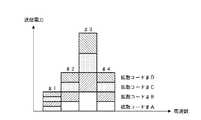
かかる構成の従来の送信装置10においては、図9に示すように、各サブキャリア(♯1〜♯4)においては重み付けによってその送信電力が異なっているが、サブキャリア内での各拡散コードごと(各ユーザごと)の送信電力は一定となっている。
【0020】
このように、従来のEGC(等利得合成)を用いたマルチキャリアCDMAシステムでは、各サブキャリアごとに重み付けを行って受信装置側での受信信号の電力を等しくするだけであったので、受信装置において拡散コード間の直交性の回復は可能であるものの、SNR(Signal to Noise Ratio)を最適化することは困難であった。
【0021】
本発明は上記実情に鑑みてなされたものであり、マルチキャリアCDMAシステムにおいて、受信装置における演算量を減らしながら、受信性能を一段と向上させることが出来る無線送信装置及び無線送信方法を提供することを目的とする。
【0022】
【課題を解決するための手段】
本発明の無線送信装置は、複数のサブキャリアに渡って信号を拡散して送信するマルチキャリアCDMAシステムの無線送信装置であって、拡散後信号に対して拡散コードごとにチップ単位で異なる重み付けを行う手段と、当該重み付けされた信号を多重する手段と、を具備し、前記重み付けに用いられる重み付け係数が、受信装置側におけるサブキャリアごとのチャネル推定値情報に基づいて拡散率を行列のサイズとする行列の固有値分解を行うことにより、受信装置側において各受信装置が逆拡散を行った際に最大固有値となる信号が取り出される係数である構成を採る。
【0023】
この構成によれば、受信装置において、受信信号のSNRの最適化と拡散コード間の直交性の確保とを両立させることができ、受信性能を向上させることができるとともに、受信装置において、簡単な構成によって受信性能を高めることが可能となる。
【0028】
本発明の無線送信方法は、複数のサブキャリアに渡って信号を拡散して送信するマルチキャリアCDMAシステムの無線送信方法であって、拡散後信号に対して拡散コードごとにチップ単位で異なる重み付けを行うステップと、当該重み付けされた信号を多重するステップと、を具備し、前記重み付けに用いられる重み付け係数が、受信装置側におけるサブキャリアごとのチャネル推定値情報に基づいて拡散率を行列のサイズとする行列の固有値分解を行うことにより、受信装置側において各受信装置が逆拡散を行った際に最大固有値となる信号が取り出される係数であるようにした。
【0029】
この方法によれば、受信装置において、受信信号のSNRの最適化と拡散コード間の直交性の確保とを両立させることができ、受信性能を向上させることができるとともに、受信装置において、簡単な構成によって受信性能を高めることが可能となる。
【0030】
【発明の実施の形態】
本発明の骨子は、マルチキャリアCDMAシステムにおいて、サブキャリアごとに重み付けを行うことに加えて、各サブキャリアに含まれる拡散コード(チップ)ごとに異なる重み付けを行うことである。
【0031】
以下、本発明の実施の形態について、図面を参照して詳細に説明する。
【0032】
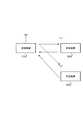
図1は本発明に係る無線通信装置100を用いたマルチキャリアCDMA方式の無線通信システムの構成を示すブロック図である。この無線通信システムにおいては、送信装置100と、複数の受信装置200、300、…との間で、マルチキャリアCDMA方式によって無線通信を行うようになされている。
【0033】
図2は送信装置100の構成を示すブロック図である。送信装置100において、コード多重数(受信装置数)だけ設けられた拡散部111、シリアル/パラレル(S/P)変換部112及び乗算器114−1〜114−4の拡散処理部110−1、110−2、…に各受信装置への送信データがそれぞれ入力される。
【0034】
拡散部111は、送信データを所定の拡散コードを用いて拡散処理した後、拡散後の信号をS/P変換部112に供給する。S/P変換部112は、拡散後のシリアル信号をパラレル信号に変換することにより、例えば4つのサブキャリアを生成し、これをそれぞれ対応する乗算器114−1〜114−4に供給する。乗算器114−1〜114−4は、それぞれ、重み係数算出部123において各サブキャリアごと及び各拡散コード(チップ)ごとに対応して算出された重み係数を各サブキャリアに乗算する。
【0035】
各重み係数を乗算した結果は、各サブキャリアに対応した加算器113−1〜113−4にそれぞれ供給される。加算器113−1は、コード多重数(受信装置数)分だけ設けられている拡散処理部110−1、110−2、…のうちの第1の拡散処理部110−1から出力される第1のサブキャリアと、第2の拡散処理部110−2から出力される第1のサブキャリアとを加算する。これにより、第1のサブキャリアには、第1のユーザ(受信装置)宛に第1の拡散コードによって拡散された信号と、第2のユーザ(受信装置)宛に第2の拡散コードによって拡散された信号とが加算される。この第1のサブキャリアはIFFT(Inverse Fast Fourier Transform)処理部115に供給される。
【0036】
また、他の加算器113−2〜113−4も同様にして、各ユーザ(受信装置)ごとに対応した拡散処理部110−1、110−2、…から出力される第2のサブキャリア同士、第3のサブキャリア同士、第4のサブキャリア同士をそれぞれ加算し、その結果をIFFT処理部115に供給する。
【0037】
IFFT処理部115は、各サブキャリアを重畳することにより、OFDM信号(マルチキャリア信号)を生成し、これをGI(Gird Interval)付加部116に供給する。GI付加部116は、OFDM信号に対してガードインターバルを付加した後、送信RF(Radio Frequency)部117に供給する。送信RF部117は、ガードインターバル挿入後の信号に対して所定の無線送信処理(例えば、D/A変換やアップコンバードなど)を行い、この無線送信処理後の信号を無線信号としてアンテナ118を介して送信する。
【0038】
送信装置100から送信された信号は、受信装置において受信される。図3は受信装置200の構成を示すブロック図である。受信装置200において、アンテナ231を介して受信RF部232に受信された受信信号は、ここで所定の無線受信処理(例えば、ダウンコンバートやA/D変換など)が施される。受信RF部232は、この無線受信処理後の信号を、GI除去部233に供給する。
【0039】
GI除去部233では、無線受信処理後の信号に挿入されているガードインターバルを除去し、このガードインターバル除去後の信号をFFT(Fast Fourier Transform)処理部234に供給する。FFT処理部234は、ガードインターバル除去後の信号に対して、シリアル/パラレル(S/P)変換し、S/P変換後の信号にFFT処理を行ってサブキャリアごとの情報に変換し、このFFT処理後の信号のうち既知信号であるパイロットシンボルを、サブキャリアごとにチャネル推定部235に供給する。
【0040】
チャネル推定部235は、サブキャリアごとのパイロットシンボルを用いてサブキャリアごとにチャネル推定を行い、得られたサブキャリアごとのチャネル推定値をMRC係数算出部236及び制御チャネル送信部239にそれぞれ供給する。
【0041】
MRC(Maximal Ratio Combining)係数算出部236では、サブキャリアごとのチャネル推定値に対して最大比合成を行うためのMRC係数を算出し、このMRC係数(受信レベルに応じた大きさの係数)を乗算器237−1〜237−4に供給する。乗算器237−1〜237−4は、FFT処理部234から出力されたFFT処理後の各サブキャリアに対して、MRC係数算出部236から供給される係数を乗算し、その乗算結果を逆拡散部238に供給することにより、MRC逆拡散処理を行う。
【0042】
また、制御チャネル送信部239は、チャネル推定部235から供給された各サブキャリアのチャネル推定値を制御チャネルで送信するためのものであり、各チャネル推定値を送信RF部240に供給する。送信RF部240は、各チャネル推定値情報に対して所定の無線送信処理(例えば、D/A変換やアップコンバードなど)を行い、この無線送信処理後の信号を無線信号としてアンテナ231を介して送信する。
【0043】
この受信装置200から送信された信号を受信した送信装置100(図2)では、その受信RF部120において、その受信信号に対して所定の無線受信処理(例えば、ダウンコンバートやA/D変換など)を行い、この無線受信処理後の信号を、制御チャネル受信部121−1、121−2、…に供給する。制御チャネル受信部121−1、121−2、…は、受信信号から制御チャネルを抽出し、この抽出された制御チャネルのデータをチャネル情報検出部122に供給する。
【0044】
チャネル情報検出部122は、制御チャネルによって受信装置からフィードバック情報として送信された各サブキャリアごとのチャネル推定値を検出し、このチャネル推定値を重み係数算出部123に供給する。重み係数算出部123は、各サブキャリア及び各拡散コード(各チップ)ごとにチャネル推定値から重み係数を算出し、算出された重み係数を乗算器114−1〜114−4に供給する。この重み係数は、受信装置側において受信信号のMRC逆拡散を行った際に、各拡散コードの直交性が確保されるような重み係数である。
【0045】
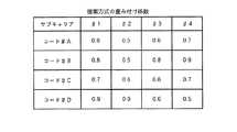
この重み係数として、例えば、図4に示すように、各サブキャリアごと及び各拡散コード(各チップごと)に算出される。この算出された重み係数を各拡散処理部110−1、110−2、…の各乗算器114−1〜114−4においてサブキャリアに乗算することにより、各サブキャリアごと及びそのサブキャリアの各拡散コード(各チップ)ごとに重み付けが行われる。
【0046】
ここで、重み係数算出部123における重み係数の算出方法について説明する。ユーザ(受信装置)数をKとして、Kユーザ分の送信ストリームSk(t)を本発明によるウェイトベクトルwkで送信する場合、このウェイトベクトルwkは、以下のように決定される。
【0047】
まず、伝搬路行列Aから求められた行列B=AHAに対する固有値ベクトルekを算出する。この固有値ベクトルekは、以下の式を満たすベクトルである。
eiHAHAei=λi(λkはk番目の固有値)
eiHAHAej=0(i≠j)
【0048】
そして、固有ベクトルekを送信ウェイトベクトルwkとして、重み係数算出部123において算出し、この算出された係数の重み付けを各サブキャリアに対して行って送信する。このような重み付け係数を用いて送信された信号x(t)は、以下によって表現される。
【0049】
【数1】
【0050】
【数2】
【0051】
次に、受信装置における受信時の重み付け係数を(Aek)Hとして、MRC処理後の信号y(t)は、次式、
【0052】
【数3】
【0053】
因みに、このとき、
eiHAHAei=λi(λkはk番目の固有値)
eiHAHAej=0(i≠j)
という上記関係を用いて式の展開を行った。
【0054】
これにより、他ユーザからの干渉が完全に除去されるとともに、受信SNRが最大となる受信が可能となる。
【0055】
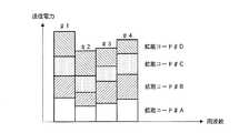
かかる構成の送信装置100においては、図5に示すように、各サブキャリア(♯1〜♯4)においては重み付けによってその送信電力が異なっており、さらにこれに加えて、サブキャリア内での各拡散コードごと(各ユーザごと)の送信電力も重み付けによってその送信電力が異なっている。そして、このような各拡散コードごとの重み係数は、受信装置200においてMRC(大きな受信レベルの信号に対しては大きな重み係数を乗算し、小さな受信レベルの信号には小さな重み係数を乗算する)を行った際に直交性が確保される値、すなわち伝搬路での直交性の崩れを予め補償するような値に設定されている。換言すれば、受信装置200においてMRCを行っても、それに用いられる重み係数は、受信信号レベルの大小関係を維持することとなるので、送信装置100において直交性を補償する重み係数を予め送信信号に乗算することで、受信装置200では直交性の確保がなされるのである。
【0056】
このような重み付けが行われた送信データを受信装置200、300、…において受信し、その受信信号に対してMRC逆拡散を行うことで、拡散コード間の直交性を確保することが可能となる。そして、MRC逆拡散本来の特性として、SNRも最適となる。
【0057】
このように、本実施の形態の送信装置100によれば、拡散後信号に対して、拡散コードごとにチップ単位で異なる重み付けを行って送信するようにしたことにより、受信装置側でMRC逆拡散を行った際に、拡散コード間の直交性を確保しながらSNRの最適な受信信号を得ることが可能となる。
【0058】
なお、上述の実施の形態においては、1対多通信を行う場合について述べたが、本発明はこれに限らず、1対1通信を行う場合にも適用することができる。
【0059】
【発明の効果】
以上説明したように、本発明によれば、マルチキャリアCDMAシステムにおいて、サブキャリアごとに重み付けを行うことに加えて、各サブキャリアに含まれる拡散コードごとに異なる重み付けを行うことにより、受信装置における受信性能を向上させることができる。
【図面の簡単な説明】
【図1】本発明の実施の形態に係る無線通信システムの構成を示すブロック図
【図2】本発明の実施の形態に係る送信装置の構成を示すブロック図
【図3】本発明の実施の形態に係る受信装置の構成を示すブロック図
【図4】本発明の実施の形態に係る重み付け係数を示す略線図
【図5】本発明の実施の形態に係る重み付け結果を示す略線図
【図6】従来の送信装置の構成を示すブロック図
【図7】従来の受信装置の構成を示すブロック図
【図8】従来の重み付け係数を示す略線図
【図9】従来の重み付け結果を示す略線図
【符号の説明】
10、100 送信装置
11、111 拡散部
12、112 S/P変換部
13−1〜13−4、113−1〜113−4 加算器
14−1〜14−4、114−1〜114−4 乗算器
15、115 IFFT処理部
16、116 GI付加部
17、40、117、240 送信RF部
20、32、120、232 受信RF部
21、121 制御チャネル受信部
22、122 チャネル情報検出部
23、123 重み係数算出部
33、233 GI除去部
34、234 FFT処理部
37−1〜37−4、237−1〜237−4 乗算器
38、238 逆拡散部
39、239 制御チャネル送信部[0001]
BACKGROUND OF THE INVENTION
The present invention relates to a multicarrier transmission wireless communication apparatus and wireless transmission method.
[0002]
[Prior art]
2. Description of the Related Art Conventionally, in a multicarrier CDMA (Code Division Multiple Access) system, transmission data is spread by a frequency axis method in a transmission apparatus, and data is transmitted after being code-multiplexed. When the transmitted data is received by the receiving apparatus under the influence of frequency selective fading, the orthogonality between the spreading codes occurs in the receiving apparatus, and the reception performance deteriorates. In order to improve orthogonality between spreading codes and improve reception performance, a method for improving reception performance by performing despreading using an algorithm such as MMSE (Minimum Mean Square Error) is widely known. (For example, refer nonpatent literature 1).
[0003]
In addition, if the power of each subcarrier is equalized in the receiving apparatus, the orthogonality between spreading codes is eliminated in the receiving apparatus, so that the receiving power of each subcarrier is equalized in advance in the receiving apparatus. A method of transmitting by adjusting the transmission power of the subcarrier is considered (see Non-Patent Document 2).
[0004]
[Non-Patent Document 1]
"Characteristics of downlink broadband OFCDM packet transmission using MMSE combining based on SIR estimation, IEICE technical report, Wireless communication system RCS2001-166 October 2001"
[Non-Patent Document 2]
"Performance of predistortion techniques for uplink MC-CDMA systems with TDD and FDD modes, International Society The Fifth International Symposium on Wireless Personal Multimedia Communications (WPMC'02) October 2002"
[0005]
[Problems to be solved by the invention]
However, in the receiving method to which the MMSE algorithm shown in Non-Patent
[0006]
In addition, the method disclosed in Non-Patent
[0007]
FIG. 6 is a block diagram showing a configuration of a
[0008]
The
[0009]
The adder 13-1 includes the first subcarrier output from the first set of the combinations of the spreading
[0010]
Similarly, other adders 13-2 to 13-4 are second subcarriers output from each set of spreading
[0011]
Outputs of the multipliers 14-1 to 14-4 are supplied to an IFFT (Inverse Fast Fourier Transform)
[0012]
The signal transmitted from the
[0013]
The
[0014]
The
[0015]
An EGC (Equal Gain Combining)
[0016]
The control
[0017]
In the transmission device 10 (FIG. 6) that has received the signal transmitted from the
[0018]
The channel
[0019]
In
[0020]
Thus, in the conventional multi-carrier CDMA system using EGC (equal gain combining), since the weight of each subcarrier is only weighted so that the power of the received signal on the receiving device side is equalized, the receiving device However, it is difficult to optimize the SNR (Signal to Noise Ratio).
[0021]
The present invention has been made in view of the above circumstances, and provides a wireless transmission device and a wireless transmission method capable of further improving reception performance in a multicarrier CDMA system while reducing the amount of calculation in the reception device. Objective.
[0022]
[Means for Solving the Problems]
The radio transmission apparatus of the present invention is a radio transmission apparatus of a multicarrier CDMA system that spreads and transmits a signal over a plurality of subcarriers, and assigns a different weight to each spread code on a chip basis for each spread code.And means for multiplexingthe weighted signal, wherein the weighting coefficient used for the weighting is based on channel estimation value information for each subcarrier on the receiving apparatus side and the matrix size. By performing eigenvalue decomposition of the matrix to be performed, a configuration is adoptedthat is a coefficient from which a signal having the maximum eigenvalue is extracted when each receiving device performs despreading on the receiving device side .
[0023]
According to this configuration, in the receiving apparatus, it is possible to achieve both optimization of the SNR of the received signal and ensuring orthogonality between spreading codes, improve reception performance, and in the receiving apparatus, The reception performance can be improved by the configuration .
[0028]
The radio transmission method of the present invention is a radio transmission method of a multi-carrier CDMA system in which a signal is spread and transmitted over a plurality of subcarriers, and a different weight is assigned to each spread code on a chip basis for each spread code.And a step of multiplexingthe weighted signal, wherein the weighting coefficient used for the weighting is based on channel estimation value information for each subcarrier on the receiving device side and a matrix size. By performing eigenvalue decomposition of the matrix, the coefficient is such thata signal having the maximum eigenvalue is extracted when each receiving device performs despreading on the receiving device side .
[0029]
According to this method, in the receiving apparatus, it is possible to achieve both optimization of the SNR of the received signal and ensuring orthogonality between spreading codes, improve reception performance, and in the receiving apparatus, The reception performance can be improved by the configuration .
[0030]
DETAILED DESCRIPTION OF THE INVENTION
The gist of the present invention is to perform different weighting for each spreading code (chip) included in each subcarrier in addition to weighting for each subcarrier in a multicarrier CDMA system.
[0031]
Hereinafter, embodiments of the present invention will be described in detail with reference to the drawings.
[0032]
FIG. 1 is a block diagram showing a configuration of a multi-carrier CDMA wireless communication system using a
[0033]
FIG. 2 is a block diagram illustrating a configuration of the
[0034]
The spreader 111 spreads transmission data using a predetermined spread code, and then supplies the spread signal to the S /
[0035]
The result of multiplying each weighting factor is supplied to adders 113-1 to 113-4 corresponding to each subcarrier. The adder 113-1 is output from the first spread processing unit 110-1 among the spread processing units 110-1, 110-2,... Provided for the number of multiplexed codes (the number of receiving devices). 1 subcarrier and the first subcarrier output from the second spreading processing section 110-2 are added. As a result, the first subcarrier is spread by the first spreading code addressed to the first user (receiving apparatus) and the second spreading code addressed to the second user (receiving apparatus). And the added signal are added. The first subcarrier is supplied to an IFFT (Inverse Fast Fourier Transform)
[0036]
Similarly, the other adders 113-2 to 113-4 also share the second subcarriers output from the spreading processing units 110-1, 110-2,... Corresponding to each user (receiving device). The third subcarriers and the fourth subcarriers are added to each other, and the result is supplied to the
[0037]
The
[0038]
The signal transmitted from the
[0039]
The
[0040]
[0041]
An MRC (Maximal Ratio Combining)
[0042]
Further, the control
[0043]
In the transmission device 100 (FIG. 2) that has received the signal transmitted from the
[0044]
The channel
[0045]
As this weighting coefficient, for example, as shown in FIG. 4, it is calculated for each subcarrier and each spreading code (each chip). Each of the subcarriers and each of the subcarriers is multiplied by the calculated weighting factor by each of the multipliers 114-1 to 114-4 of each spreading processing section 110-1, 110-2,. Weighting is performed for each spreading code (each chip).
[0046]
Here, a method of calculating a weighting factor in the weighting
[0047]
First, to calculate the eigenvectors ek for the matrix B = AH A obtained from the channel matrix A. The eigenvalue vectorek is a vector that satisfies the following expression.
eiH AH Aei = λi (λk is the k-th eigenvalue)
eiH AH Aej = 0 (i ≠ j)
[0048]
Then, the eigenvector ek is calculated as a transmission weight vector wk by the weight
[0049]
[Expression 1]
[0050]
[Expression 2]
[0051]
Next, assuming that the weighting coefficient at the time of reception in the receiving device is (Aek )H , the signal y (t) after the MRC processing is given by the following equation:
[0052]
[Equation 3]
[0053]
By the way,
eiH AH Aei = λi (λk is the k-th eigenvalue)
eiH AH Aej = 0 (i ≠ j)
The formula was developed using the above relationship.
[0054]
As a result, interference from other users is completely removed, and reception with the maximum received SNR becomes possible.
[0055]
In
[0056]
.. Are received by receiving
[0057]
As described above, according to transmitting
[0058]
In the above-described embodiment, the case of performing one-to-many communication has been described. However, the present invention is not limited to this and can be applied to the case of performing one-to-one communication.
[0059]
【The invention's effect】
As described above, according to the present invention, in the multicarrier CDMA system, in addition to performing weighting for each subcarrier, different weighting is performed for each spreading code included in each subcarrier. Reception performance can be improved.
[Brief description of the drawings]
FIG. 1 is a block diagram showing a configuration of a wireless communication system according to an embodiment of the present invention. FIG. 2 is a block diagram showing a configuration of a transmitting apparatus according to an embodiment of the present invention. FIG. 4 is a schematic diagram illustrating a weighting coefficient according to an embodiment of the present invention. FIG. 5 is a schematic diagram illustrating a weighting result according to an embodiment of the present invention. FIG. 6 is a block diagram showing the configuration of a conventional transmitting apparatus. FIG. 7 is a block diagram showing the configuration of a conventional receiving apparatus. FIG. 8 is a schematic diagram showing conventional weighting coefficients. Outline diagram [Explanation of symbols]
10, 100
Claims (2)
Translated fromJapanese拡散後信号に対して拡散コードごとにチップ単位で異なる重み付けを行う手段と、
当該重み付けされた信号を多重する手段と、を具備し、
前記重み付けに用いられる重み付け係数が、受信装置側におけるサブキャリアごとのチャネル推定値情報に基づいて拡散率を行列のサイズとする行列の固有値分解を行うことにより、受信装置側において各受信装置が逆拡散を行った際に最大固有値となる信号が取り出される係数である、
無線送信装置。A wireless transmission device of a multicarrier CDMA system that spreads and transmits a signal over a plurality of subcarriers,
Means forperforming different weighting for each spreading code on a chip-by-chip basis for the spread signal;
Means for multiplexingthe weighted signal,
The weighting coefficient used for the weighting performs eigenvalue decomposition of the matrix having the spreading factor as the matrix size based on channel estimation value information for each subcarrier on the receiving device side, whereby each receiving device is inverted on the receiving device side. This is the coefficient for extracting the signal that is the largest eigenvalue when spreading.
Wireless transmission device.
拡散後信号に対して拡散コードごとにチップ単位で異なる重み付けを行うステップと、
当該重み付けされた信号を多重するステップと、を具備し、
前記重み付けに用いられる重み付け係数が、受信装置側におけるサブキャリアごとのチャネル推定値情報に基づいて拡散率を行列のサイズとする行列の固有値分解を行うことにより、受信装置側において各受信装置が逆拡散を行った際に最大固有値となる信号が取り出される係数である、
無線送信方法。A wireless transmission method of a multi-carrier CDMA system that spreads and transmits a signal over a plurality of subcarriers,
Performing different weights ona chip-by-chip basis for each spread code on the spread signal;
Multiplexingthe weighted signal; and
The weighting coefficient used for the weighting performs eigenvalue decomposition of the matrix having the spreading factor as the matrix size based on channel estimation value information for each subcarrier on the receiving device side, whereby each receiving device is inverted on the receiving device side. This is the coefficient for extracting the signal that is the largest eigenvalue when spreading.
Wireless transmission method.
Priority Applications (7)
| Application Number | Priority Date | Filing Date | Title |
|---|---|---|---|
| JP2002375265AJP4163942B2 (en) | 2002-12-25 | 2002-12-25 | Wireless communication apparatus and wireless transmission method |
| AU2003289057AAU2003289057A1 (en) | 2002-12-25 | 2003-12-12 | Radio communication apparatus and radio transmission method |
| US10/539,088US7586866B2 (en) | 2002-12-25 | 2003-12-12 | Radio communication apparatus and radio transmission method |
| EP03778873AEP1578046A4 (en) | 2002-12-25 | 2003-12-12 | RADIO COMMUNICATION DEVICE AND RADIO TRANSMISSION METHOD |
| PCT/JP2003/015946WO2004062153A1 (en) | 2002-12-25 | 2003-12-12 | Radio communication apparatus and radio transmission method |
| CNB2003801073461ACN100574166C (en) | 2002-12-25 | 2003-12-12 | Wireless communication device and wireless transmission method |
| US12/511,854US8270427B2 (en) | 2002-12-25 | 2009-07-29 | Radio communication apparatus and radio transmission method |
Applications Claiming Priority (1)
| Application Number | Priority Date | Filing Date | Title |
|---|---|---|---|
| JP2002375265AJP4163942B2 (en) | 2002-12-25 | 2002-12-25 | Wireless communication apparatus and wireless transmission method |
Publications (2)
| Publication Number | Publication Date |
|---|---|
| JP2004208070A JP2004208070A (en) | 2004-07-22 |
| JP4163942B2true JP4163942B2 (en) | 2008-10-08 |
Family
ID=32708244
Family Applications (1)
| Application Number | Title | Priority Date | Filing Date |
|---|---|---|---|
| JP2002375265AExpired - LifetimeJP4163942B2 (en) | 2002-12-25 | 2002-12-25 | Wireless communication apparatus and wireless transmission method |
Country Status (6)
| Country | Link |
|---|---|
| US (2) | US7586866B2 (en) |
| EP (1) | EP1578046A4 (en) |
| JP (1) | JP4163942B2 (en) |
| CN (1) | CN100574166C (en) |
| AU (1) | AU2003289057A1 (en) |
| WO (1) | WO2004062153A1 (en) |
Families Citing this family (12)
| Publication number | Priority date | Publication date | Assignee | Title |
|---|---|---|---|---|
| JP4163942B2 (en)* | 2002-12-25 | 2008-10-08 | 松下電器産業株式会社 | Wireless communication apparatus and wireless transmission method |
| US7826435B1 (en)* | 2004-03-05 | 2010-11-02 | Zte (Usa) Inc. | Power control in OFDM and OFDMA wireless communication networks |
| BRPI0513071A (en)* | 2004-08-05 | 2008-04-22 | Matsushita Electric Industrial Co Ltd | radio transmission device, radio reception device, radio transmission method and radio reception method |
| US8054783B2 (en)* | 2004-08-06 | 2011-11-08 | Nextel Communications Inc. | System and method for dividing subchannels in a OFDMA network |
| US7881412B2 (en) | 2005-11-21 | 2011-02-01 | Qualcomm Incorporated | Quasi-linear interference cancellation for wireless communication |
| MX2008014883A (en)* | 2006-05-25 | 2008-12-05 | Koninl Philips Electronics Nv | Ultra wide band wireless radio transmission in mri systems involving channel estimation. |
| JP4836186B2 (en)* | 2006-05-31 | 2011-12-14 | 三洋電機株式会社 | Transmitter |
| JP2009118388A (en)* | 2007-11-09 | 2009-05-28 | Nec Electronics Corp | Receiver |
| KR101192359B1 (en)* | 2007-12-17 | 2012-10-18 | 삼성전자주식회사 | NAND flash memory device and method for manufacturing the same |
| KR100925440B1 (en) | 2008-01-28 | 2009-11-06 | 엘지전자 주식회사 | Method for allocating physical hybrid ARQ indicator channel |
| EP2159979A1 (en)* | 2008-08-29 | 2010-03-03 | Nokia Siemens Networks OY | In-band ripple compensation |
| JP5841433B2 (en)* | 2012-01-11 | 2016-01-13 | 日東電工株式会社 | Intraoral film-form base and preparation |
Family Cites Families (21)
| Publication number | Priority date | Publication date | Assignee | Title |
|---|---|---|---|---|
| US6680928B1 (en)* | 1997-07-22 | 2004-01-20 | Ericsson Inc. | Communications system and method for multi-carrier orthogonal coding |
| US6351458B2 (en)* | 1997-09-22 | 2002-02-26 | Matsushita Electric Industrial Co., Ltd. | CDMA cellular wireless communication system |
| JPH11274983A (en)* | 1998-03-26 | 1999-10-08 | Mitsubishi Electric Corp | CDMA amplitude limiting device, CDMA amplitude restoring device, CDMA amplitude limiting / restoring device, CDMA transmitting device, CDMA receiving device, CDMA amplitude limiting method, and CDMA amplitude restoring method |
| DE69936019T2 (en)* | 1998-07-24 | 2007-08-30 | Matsushita Electric Industrial Co. Limited, Kadoma | CDMA radio transmission system and method |
| JP3411850B2 (en) | 1998-07-24 | 2003-06-03 | 松下電器産業株式会社 | CDMA wireless communication device and CDMA wireless communication method |
| JP3411854B2 (en) | 1998-07-24 | 2003-06-03 | 松下電器産業株式会社 | Receiving device and transmitting device |
| EP1011281A3 (en)* | 1998-12-18 | 2000-07-05 | TELEFONAKTIEBOLAGET L M ERICSSON (publ) | Flexible CDMA combiner |
| AU6048100A (en) | 1999-06-28 | 2001-01-31 | Ericsson Inc. | Communications system and method for multi-carrier orthogonal coding |
| US6996080B1 (en)* | 1999-07-23 | 2006-02-07 | Itt Manufacturing Enterprises, Inc. | Chip-synchronous CDMA multiplexer and method resulting in constant envelope signals |
| US6515980B1 (en)* | 1999-09-22 | 2003-02-04 | Ericsson Inc. | Methods and apparatus for interference cancellation using complex interference orthogonalization techniques |
| JP2002190788A (en)* | 2000-03-17 | 2002-07-05 | Matsushita Electric Ind Co Ltd | Wireless communication device and wireless communication method |
| EP1179904A4 (en)* | 2000-03-17 | 2006-09-27 | Matsushita Electric Industrial Co Ltd | METHOD AND DEVICE FOR RADIO MESSAGE TRANSMISSION |
| US6671340B1 (en)* | 2000-06-15 | 2003-12-30 | Ibiquity Digital Corporation | Method and apparatus for reduction of interference in FM in-band on-channel digital audio broadcasting receivers |
| JP3576075B2 (en)* | 2000-06-28 | 2004-10-13 | 独立行政法人 科学技術振興機構 | Interference canceller, wireless terminal device, and interference canceling method |
| KR100576665B1 (en)* | 2000-07-26 | 2006-05-10 | 미쓰비시덴키 가부시키가이샤 | Multi-carrier cdma communication device, multi-carrier cdma transmitting device, and multi-carrier cdma receiving device |
| JP2002135185A (en)* | 2000-10-19 | 2002-05-10 | Hitachi Kokusai Electric Inc | Receiving machine |
| JP3679014B2 (en)* | 2001-02-08 | 2005-08-03 | 松下電器産業株式会社 | Wireless communication device |
| JP3679018B2 (en)* | 2001-03-14 | 2005-08-03 | 松下電器産業株式会社 | Wireless communication apparatus and wireless communication method |
| US7236452B2 (en)* | 2001-08-28 | 2007-06-26 | Ntt Docomo, Inc. | Multi-carrier CDMA transmission system, transmitting apparatus and receiving apparatus used in this system, and multi-carrier CDMA transmission method |
| US6873651B2 (en)* | 2002-03-01 | 2005-03-29 | Cognio, Inc. | System and method for joint maximal ratio combining using time-domain signal processing |
| JP4163942B2 (en)* | 2002-12-25 | 2008-10-08 | 松下電器産業株式会社 | Wireless communication apparatus and wireless transmission method |
- 2002
- 2002-12-25JPJP2002375265Apatent/JP4163942B2/ennot_activeExpired - Lifetime
- 2003
- 2003-12-12WOPCT/JP2003/015946patent/WO2004062153A1/ennot_activeCeased
- 2003-12-12USUS10/539,088patent/US7586866B2/ennot_activeExpired - Lifetime
- 2003-12-12CNCNB2003801073461Apatent/CN100574166C/ennot_activeExpired - Fee Related
- 2003-12-12EPEP03778873Apatent/EP1578046A4/ennot_activeWithdrawn
- 2003-12-12AUAU2003289057Apatent/AU2003289057A1/ennot_activeAbandoned
- 2009
- 2009-07-29USUS12/511,854patent/US8270427B2/ennot_activeExpired - Fee Related
Also Published As
| Publication number | Publication date |
|---|---|
| US7586866B2 (en) | 2009-09-08 |
| CN1732643A (en) | 2006-02-08 |
| EP1578046A1 (en) | 2005-09-21 |
| US8270427B2 (en) | 2012-09-18 |
| WO2004062153A1 (en) | 2004-07-22 |
| EP1578046A4 (en) | 2011-08-24 |
| US20060067207A1 (en) | 2006-03-30 |
| US20090290568A1 (en) | 2009-11-26 |
| AU2003289057A1 (en) | 2004-07-29 |
| CN100574166C (en) | 2009-12-23 |
| JP2004208070A (en) | 2004-07-22 |
Similar Documents
| Publication | Publication Date | Title |
|---|---|---|
| JP6270798B2 (en) | Signal generation and detection device, signal generation device and signal detection device | |
| US8270427B2 (en) | Radio communication apparatus and radio transmission method | |
| US7218666B2 (en) | Method and system for transmission and frequency domain equalization for wideband CDMA system | |
| US7099299B2 (en) | CDMA system with frequency domain equalization | |
| JP3678944B2 (en) | Wireless communication apparatus and wireless communication method | |
| EP1396956A1 (en) | MC-CDMA downlink beamforming method with the weights applied to every element of the antenna array being different for every user and every frequency bin, the weights being adapted to maximise the signal to interference and noise ratio | |
| US7466969B2 (en) | MIMO receiver, MIMO reception method and wireless communication system | |
| JP4043287B2 (en) | Wireless communication system, communication apparatus, and reception quality measuring method | |
| CN102177663B (en) | A method of processing received signals and corresponding receiver | |
| EP1328071B1 (en) | MC-CDMA uplink per carrier pre-distortion method | |
| JP4756506B2 (en) | Digital signal equalization method and equalizer | |
| JP2003249911A (en) | Pre-distortion method for telecommunication system and transmitter for mobile terminal of mc-cdma telecommunication system | |
| JPWO2004032375A1 (en) | Transmission power control method and transmission power control apparatus in OFDM-CDMA | |
| CN107317612B (en) | Transmission device, reception device, transmission method, reception method, and communication system | |
| JP4130825B2 (en) | Design method of uplink pilot signal in multi-carrier code division multiple access system | |
| JP4567749B2 (en) | Method and apparatus for performing chip level equalization using combined processing | |
| JP4134609B2 (en) | Multi-carrier CDMA communication system, demodulation processing circuit thereof, receiving apparatus, demodulation processing method and reception method | |
| Salzer et al. | Comparison of antenna array techniques for the downlink of multi-carrier CDMA systems | |
| JP2010193350A (en) | Communication apparatus and communication system | |
| CN100493061C (en) | A Signal Detection Method Based on Orthogonal Packet MC-CDMA Downlink Combined with Frequency Offset Compensation | |
| JP2003283462A (en) | Multi-carrier CDMA receiver | |
| Punnoose et al. | Blind channel estimation for multiple input multiple output uplink guard-band assisted code division multiple access systems with layered space frequency equalisation | |
| JP2007110203A (en) | Radio communication system, radio communication equipment and wireless communication method, and computer program | |
| Trivedi et al. | Pilot based adaptive channel estimation and tracking in uplink MC-CD MA using Kalman filter | |
| Zhang | Performance analysis and enhancement of multicarrier transmission systems |
Legal Events
| Date | Code | Title | Description |
|---|---|---|---|
| A621 | Written request for application examination | Free format text:JAPANESE INTERMEDIATE CODE: A621 Effective date:20050906 | |
| A131 | Notification of reasons for refusal | Free format text:JAPANESE INTERMEDIATE CODE: A131 Effective date:20080226 | |
| A521 | Request for written amendment filed | Free format text:JAPANESE INTERMEDIATE CODE: A523 Effective date:20080414 | |
| TRDD | Decision of grant or rejection written | ||
| A01 | Written decision to grant a patent or to grant a registration (utility model) | Free format text:JAPANESE INTERMEDIATE CODE: A01 Effective date:20080701 | |
| A01 | Written decision to grant a patent or to grant a registration (utility model) | Free format text:JAPANESE INTERMEDIATE CODE: A01 | |
| A61 | First payment of annual fees (during grant procedure) | Free format text:JAPANESE INTERMEDIATE CODE: A61 Effective date:20080725 | |
| FPAY | Renewal fee payment (event date is renewal date of database) | Free format text:PAYMENT UNTIL: 20110801 Year of fee payment:3 | |
| R150 | Certificate of patent or registration of utility model | Ref document number:4163942 Country of ref document:JP Free format text:JAPANESE INTERMEDIATE CODE: R150 Free format text:JAPANESE INTERMEDIATE CODE: R150 | |
| FPAY | Renewal fee payment (event date is renewal date of database) | Free format text:PAYMENT UNTIL: 20110801 Year of fee payment:3 | |
| FPAY | Renewal fee payment (event date is renewal date of database) | Free format text:PAYMENT UNTIL: 20120801 Year of fee payment:4 | |
| FPAY | Renewal fee payment (event date is renewal date of database) | Free format text:PAYMENT UNTIL: 20130801 Year of fee payment:5 | |
| S111 | Request for change of ownership or part of ownership | Free format text:JAPANESE INTERMEDIATE CODE: R313113 | |
| S533 | Written request for registration of change of name | Free format text:JAPANESE INTERMEDIATE CODE: R313533 | |
| R350 | Written notification of registration of transfer | Free format text:JAPANESE INTERMEDIATE CODE: R350 | |
| R250 | Receipt of annual fees | Free format text:JAPANESE INTERMEDIATE CODE: R250 | |
| EXPY | Cancellation because of completion of term |