JP4162377B2 - Improvements regarding injection devices - Google Patents
Improvements regarding injection devicesDownload PDFInfo
- Publication number
- JP4162377B2 JP4162377B2JP2000507418AJP2000507418AJP4162377B2JP 4162377 B2JP4162377 B2JP 4162377B2JP 2000507418 AJP2000507418 AJP 2000507418AJP 2000507418 AJP2000507418 AJP 2000507418AJP 4162377 B2JP4162377 B2JP 4162377B2
- Authority
- JP
- Japan
- Prior art keywords
- barrel
- connector
- injection device
- syringe carrier
- syringe
- Prior art date
- Legal status (The legal status is an assumption and is not a legal conclusion. Google has not performed a legal analysis and makes no representation as to the accuracy of the status listed.)
- Expired - Lifetime
Links
- 238000002347injectionMethods0.000titleclaimsabstractdescription53
- 239000007924injectionSubstances0.000titleclaimsabstractdescription53
- 238000010304firingMethods0.000claimsabstractdescription37
- 238000000465mouldingMethods0.000claimsdescription12
- 239000003814drugSubstances0.000claimsdescription4
- 229940079593drugDrugs0.000claimsdescription4
- 238000003780insertionMethods0.000claimsdescription3
- 230000037431insertionEffects0.000claimsdescription3
- 230000013011matingEffects0.000claimsdescription2
- 230000002028prematureEffects0.000claims1
- 239000002775capsuleSubstances0.000description11
- 239000007788liquidSubstances0.000description6
- 239000000843powderSubstances0.000description3
- 239000000126substanceSubstances0.000description3
- 230000004888barrier functionEffects0.000description2
- 239000000463materialSubstances0.000description2
- 239000012528membraneSubstances0.000description2
- 238000000034methodMethods0.000description2
- 239000000203mixtureSubstances0.000description2
- 230000000295complement effectEffects0.000description1
- 239000008176lyophilized powderSubstances0.000description1
- 238000004519manufacturing processMethods0.000description1
- 230000037368penetrate the skinEffects0.000description1
- 230000000149penetrating effectEffects0.000description1
- 230000035515penetrationEffects0.000description1
- 238000003825pressingMethods0.000description1
- 239000000243solutionSubstances0.000description1
- 230000000007visual effectEffects0.000description1
- XLYOFNOQVPJJNP-UHFFFAOYSA-NwaterSubstancesOXLYOFNOQVPJJNP-UHFFFAOYSA-N0.000description1
Images


Classifications
- A—HUMAN NECESSITIES
- A61—MEDICAL OR VETERINARY SCIENCE; HYGIENE
- A61M—DEVICES FOR INTRODUCING MEDIA INTO, OR ONTO, THE BODY; DEVICES FOR TRANSDUCING BODY MEDIA OR FOR TAKING MEDIA FROM THE BODY; DEVICES FOR PRODUCING OR ENDING SLEEP OR STUPOR
- A61M5/00—Devices for bringing media into the body in a subcutaneous, intra-vascular or intramuscular way; Accessories therefor, e.g. filling or cleaning devices, arm-rests
- A61M5/178—Syringes
- A61M5/20—Automatic syringes, e.g. with automatically actuated piston rod, with automatic needle injection, filling automatically
- A61M5/2033—Spring-loaded one-shot injectors with or without automatic needle insertion
- A—HUMAN NECESSITIES
- A61—MEDICAL OR VETERINARY SCIENCE; HYGIENE
- A61M—DEVICES FOR INTRODUCING MEDIA INTO, OR ONTO, THE BODY; DEVICES FOR TRANSDUCING BODY MEDIA OR FOR TAKING MEDIA FROM THE BODY; DEVICES FOR PRODUCING OR ENDING SLEEP OR STUPOR
- A61M5/00—Devices for bringing media into the body in a subcutaneous, intra-vascular or intramuscular way; Accessories therefor, e.g. filling or cleaning devices, arm-rests
- A61M5/178—Syringes
- A61M5/20—Automatic syringes, e.g. with automatically actuated piston rod, with automatic needle injection, filling automatically
- A61M2005/2073—Automatic syringes, e.g. with automatically actuated piston rod, with automatic needle injection, filling automatically preventing premature release, e.g. by making use of a safety lock
- A—HUMAN NECESSITIES
- A61—MEDICAL OR VETERINARY SCIENCE; HYGIENE
- A61M—DEVICES FOR INTRODUCING MEDIA INTO, OR ONTO, THE BODY; DEVICES FOR TRANSDUCING BODY MEDIA OR FOR TAKING MEDIA FROM THE BODY; DEVICES FOR PRODUCING OR ENDING SLEEP OR STUPOR
- A61M5/00—Devices for bringing media into the body in a subcutaneous, intra-vascular or intramuscular way; Accessories therefor, e.g. filling or cleaning devices, arm-rests
- A61M5/178—Syringes
- A61M5/1782—Devices aiding filling of syringes in situ
- A—HUMAN NECESSITIES
- A61—MEDICAL OR VETERINARY SCIENCE; HYGIENE
- A61M—DEVICES FOR INTRODUCING MEDIA INTO, OR ONTO, THE BODY; DEVICES FOR TRANSDUCING BODY MEDIA OR FOR TAKING MEDIA FROM THE BODY; DEVICES FOR PRODUCING OR ENDING SLEEP OR STUPOR
- A61M5/00—Devices for bringing media into the body in a subcutaneous, intra-vascular or intramuscular way; Accessories therefor, e.g. filling or cleaning devices, arm-rests
- A61M5/50—Devices for bringing media into the body in a subcutaneous, intra-vascular or intramuscular way; Accessories therefor, e.g. filling or cleaning devices, arm-rests having means for preventing re-use, or for indicating if defective, used, tampered with or unsterile
- A61M5/5086—Devices for bringing media into the body in a subcutaneous, intra-vascular or intramuscular way; Accessories therefor, e.g. filling or cleaning devices, arm-rests having means for preventing re-use, or for indicating if defective, used, tampered with or unsterile for indicating if defective, used, tampered with or unsterile
Landscapes
- Health & Medical Sciences (AREA)
- Animal Behavior & Ethology (AREA)
- Veterinary Medicine (AREA)
- Anesthesiology (AREA)
- Biomedical Technology (AREA)
- Heart & Thoracic Surgery (AREA)
- Hematology (AREA)
- Life Sciences & Earth Sciences (AREA)
- Vascular Medicine (AREA)
- Engineering & Computer Science (AREA)
- General Health & Medical Sciences (AREA)
- Public Health (AREA)
- Infusion, Injection, And Reservoir Apparatuses (AREA)
- Polarising Elements (AREA)
- Medical Preparation Storing Or Oral Administration Devices (AREA)
- Injection Moulding Of Plastics Or The Like (AREA)
- Chemical Or Physical Treatment Of Fibers (AREA)
- Consolidation Of Soil By Introduction Of Solidifying Substances Into Soil (AREA)
- Feeding, Discharge, Calcimining, Fusing, And Gas-Generation Devices (AREA)
Abstract
Description
Translated fromJapanese【0001】
本発明は、注射装置に関する。
【0002】
注射後、針のついた注射器は、安全のために、ガード付きの容器に捨てられる。しかし、まず注射器を前方に発射して針を貫入させてから、注射器ピストンを前方に押して投与薬を射出させ、最後に注射器と針を引き込む、再使用できる装置から、注射器をはずすことは、それ自身危険であり、また時間のかかることである。
【0003】
一つの答は、すべてを廃棄することであるが、前記のような注射装置は複雑であり高価である。したがって、これは実際的な選択ではない。
【0004】
しかし、装置を二つの部分に分けて製造し、一つの部分を、解放してばねで前方に進ませることのできるプランジャーを有する再使用可能な発射機構とし、他の部分を、発射機構を一時的に取りつけることのできる、注射器のためのハウジングおよびガイドとすれば、後者の部分を(注射器を収容したまま)投棄するようにすることができる。
【0005】
やはり有用なことは、装置が使用済みであるか否かを一目で知ることができ、また使用前および使用後に針の突き出しを積極的に防ぐ何らかの安全対策を有することである。
【0006】
本発明の目的は、そのような装置を提供することである。
【0007】
本発明の一つの側面によれば、 バレル、該バレル内にある注射器キャリヤー、ばね手段、およびコネクターから成る注射装置であって、 前記注射器キャリヤーが、該注射器キャリヤーによって保持される注射器の針が前記バレルの前部内に引き込まれている後方位置と、前記針が前記バレルの前部から突き出ている前方位置との間で、軸方向に可動であり、 前記ばね手段が前記注射器キャリヤーを前記後方位置に向けて押し、 前記コネクターが、発射装置の取り付けのために前記バレルの後端において限られた軸方向運動の自由度を有し、前記発射装置の発射部材が、解放されると、注射器内のピストンに作用して注射器を前方に押し、そのあと投与薬を射出する注射装置において、 コネクターと注射器キャリヤーのうち少なくとも一つが最初、バレルに横方向に挿入される取りはずし可能な固定部材によってバレルに対して不動に保たれ、 発射装置が前方に押されることによりバレルが皮膚に押しつけて保持されたとき、固定部材の取りはずしにより、コネクターと注射器キャリヤーが、該注射器キャリヤーとその注射器が発射装置の作動により前方に押される配置をとり、 注射器キャリヤーが、前記注射装置を皮膚から引き離したあと、ばね手段の作用下で後方位置に戻ることを特徴とする注射装置、が提供される。
【0008】
前記のことからわかるように、明らかにこの注射装置は、固定部材が所定の位置にあるかぎり、使用不可の状態にある。固定部材が取りはずされてしまっているならば、それは、その注射装置が使用済みであり、廃棄すべきである、ということを示す。もちろんこれは単なる視覚的信号ではなく、第一義的には、動作に対する物理的障壁である。
【0009】
使用後に固定部材をもとに戻すことができず、したがって新しい注射装置であるという印象を与えないことを確実にするために、好ましくは、最初固定部材によって係合していた戻り止めが、もはや、固定部材が貫入していたバレルの開口と合っていない位置で、コネクターおよび注射器キャリヤーのどちらかまたは両方がそれぞれ動作を終えるように構成する。コネクターがバレル内の戻り止めとスナップ係合して、戻り止めを使用後位置に捕捉することができ、一方ばね手段が注射器キャリヤーをその固定位置の後方まで押すことができるようにすることができる。
【0010】
好ましくは、ばね手段が初期固定位置において部分的に圧縮されており、したがって固定部材が取りはずされたとき、ばね手段が注射器キャリヤーを後方に押し、針の先端がぎりぎり突き出た位置に近い位置からバレル内にさらにはいり込み、キャップの取りはずしが可能になるようにする。同時に、注射器キャリヤーがコネクターに作用して該コネクターを後方に押すが、該コネクターが最終の使用後位置に捕捉されるほど遠くまでは押さない、ようにすることができる。便利なのは、コネクター上のスナップ係合要素が、前記注射装置の発射の前に注射器キャリヤーとコネクターとの相互係合により、無効にされ、この無効状態にある前記係合要素が、コネクターの後方運動を制限する止めを形成するようにすることである。
【0011】
注射後、ばね手段が注射器キャリヤー、注射器、および発射装置の発射部材を通じて作用して、コネクターを後方の捕捉位置に逆戻りさせ、注射器キャリヤーとコネクターとの軸方向関係が変化して、スナップ係合要素を無効にして発射前の後方運動を制限する相互係合が解除されるようにする。
【0012】
便利なのは、発射装置のコネクターへの取り付けがかみ合いねじによるものであり、コネクターがバレルに対する回転に対して拘束されるようにすることである。
【0013】
コネクターがステップのついた管であり、小径の後端部が発射装置を受けるソケットを与え、前記ステップによって形成される内部の前方に向いた肩が注射器キャリヤーの後端に対する接触部分を与え、またコネクターが使用後の位置にあるとき、前記ステップによって形成される外部の後方向きの肩が、バレルの後部にはめられた固定リングとの係合のための接触部分を与えるようにすることができる。
【0014】
注射器キャリヤーが、バレルの内部の接触部分によって定められる前方運動の制限範囲を有するようにすることができる。この接触部分は、注射器キャリヤーをバレルと同軸に保つためのガイド手段の後端によって与えることができ、該接触部分に対して、注射器キャリヤーの後端のフランジが接触する。また、このフランジは、固定部材が係合する戻り止めを与えることもできる。
【0015】
便利なのは、ばね手段をコイルばねとし、該コイルばねが針ユニットを包囲して注射器キャリヤーの前端と係合し、またバレルの前部内の接触部分に対して反作用するようにすることである。
【0016】
好ましくは、バレルの前部が、内部に口の方を指したガイド成形物を備えている。これらのガイド成形物は、針の突き出しと針キャップの取りはずしとを許すが、指を挿入して引っ込んでいる針に接触することを事実上不可能にするようなものである。
【0017】
便利なのは、ガイド成形物の根本がばね手段のための接触部分を与えるようにすることである。
【0018】
前記の注射装置は、主として、注射直前に混合しなければならない二成分から成る投与薬を収容する注射器に対して使用することを意図するものである。一つの成分は最初から注射器にはいっている液体(単なる水であることもある)であり、一方他の成分は該液体中に分散するかまたは該液体と溶液を形成する粉末である。
【0019】
以下、本発明のさらに十分な理解のために、添付の図面を参照しつつ、例として、一つの実施態様について説明する。
【0020】
注射装置は、バレル1を有し、該バレルは、テーパの付いた前部2と大体円筒形の後部3とを有する。この後部3には、ステップの付いた管形状のコネクター4がはめ込まれ、該コネクター4の小径の後端部5はねじの切られたソケットを形成している。長さ方向の中ほどに、外部の、後方に向いた肩6と、内部の、前方に向いた肩7とがある。コネクター4の前端部8は、これらの肩のすぐ前方に戻り止め9を規定する開口を有する。この開口の目的については後述する。図2からもっともよくわかるように、実際には、この開口は狭いU字形スロット10の基底部であり、このスロットにより、フィンガー11が形成され、フィンガー11は、該フィンガーが作られているプラスチック材料の弾力ある柔軟性により、前端部8に該フィンガーの前端で有効に丁番付けされている。フィンガー11は、後端に、外側に突き出たラグ12を有し、スナップ係合要素を規定する。ステップの付いたコネクター4は、前端部8の溝に係合する、バレル1内部のスプライン13によって、バレル1に対する回転が防がれている。
【0021】
前記バレルに、テーパ付き前部2の大部分にわたって、ガイド手段14を規定する内部ガイドリブが備えられ、これらのリブは後方に向いた肩に終っており、該肩が接触部分15を規定する。また、バレル1は、固定リング16によって後方に、ある短い長さだけ延長されている。固定リング16は、後部3とコネクター4の小径の後端部5との間のスリーブ継手となっており、スナップばめのリブと溝の構成17によって保持されていて、バレルの後部に対して接触する肩18を有する。固定リング16は、戻り止め20を規定する開口と面取りされた端とを備えた前方に突き出たタング19を有する。
【0022】
バレル1内には注射器21があり、注射器21は、前端に針ユニット23を有するカプセル22を有するが、実際の針23Aは最初キャップ24で包囲されている。カプセル22は注射器キャリヤー25であるスリーブによって包囲、支持されている。該スリーブは、後端に外側に突き出たリム26を有し、該リムは局所的に厚くなっていて、戻り止め27を規定する切り欠きを有する。該切り欠きは、該スリーブの後端が肩7に接触するとき、戻り止め9を規定する開口と位置が合う。該スリーブは、前端に、内向きに曲ったフランジ28および29を有し、後方にあるフランジ28は針ユニット23の基底部に対する接触部を与え、前方にあるフランジ29はU字形であり、したがって針アセンブリの基底部が横方向にはいることができる。この操作は製造時に行われ、したがって使用者は、実際に注射が行われるときを除いて、針23Aに接近することはできない。コイルばねの形状のばね手段30の後端はフランジ29に接触しており、前端はいくつかのフィンガーから成るガイド成形物31に係合している。これらのフィンガーはバレルの軸のまわりに対称に配置してあり、内側、前方を指したガイド成形物を形成し、これらのガイド成形物はバレル1の口で終っている。これらのガイド成形物は必要に応じて曲ることができて、キャップ24の引き抜きを許すものであり、また針23Aの突き出しを妨げない。しかし、これらのガイド成形物は指の挿入に対しては有効な障壁となるものである。バレルの口はノーズピース32によって包囲されており、このノーズピース32は、患者への針の貫入深さを大きくしたいときには取りはずすことができる。
【0023】
バレルの円筒形の後端部3には開口33があり、この開口33は最初戻り止め9を規定する開口と位置が合っている。T字形の固定部材34は短いステム35と長い非対称の直交部材36を有し、ステム35は、開口33および戻り止め9を規定する開口内に挿入され、先端が切り欠き27に係合する。一方、直交部材36は、バレルに密接して長さ方向に配置され、テーパ付きの前部2の開始部を越えて延びており、したがって隙間が形成され、この隙間により、直交部材を取りはずすことができる。図1の、集成された"供給されたまま"の状態では、この固定部材34は注射器キャリヤー25が長さ方向の移動をしないで確実に保持されることを保証する。また、この固定部材はコネクター4をその前端が接触部分15を規定する肩に接触するように保持する。
【0024】
この装置は公知の発射装置37に取りつけるように設計されている。この発射装置については詳しくは述べないが、この発射装置は後端にトリガーボタン38を有し、該トリガーボタン38を操作すると、発射部材39を規定するプランジャーが前端から突き出され、小径の後端部5により規定されたソケット内に押し込まれる。好ましくは、トリガーボタン38は安全位置を有し、該位置から回転させてからでなければ、該プランジャーを解放するためにトリガーボタン38を押すことができないようにする。
【0025】
この発射装置37は使用の直前に取りつけ、次に、バレル1から突き出ているキャップ24を引っ張ってはずし、バレル内で針23Aを露出させる。最後に、キャップ24がひきはなされているときに注射器と注射器キャリヤーが前方にひきずられるのを防いでいた固定部材34を取りはずす。すると、わずかに圧縮されていたばね手段30が作用することができ、バレル1を、タング19の前端がラグ12に接触する位置に来るまで、前方に押す。この位置において、ラグ12は、注射器キャリヤー25であるスリーブのリム26のためタング19の下に曲ることはできない。これが図3の位置である。
【0026】
次に、ノーズピース32が皮膚に当てられ、発射装置37が前方に押されて、コネクター4がふたたび接触部分15を規定する肩に接触する位置に来て止められるまで、バレル内にはいり込む。これにより、針23Aの先端がバレルの口内に戻るが、あまり突き出ていない。トリガーボタン38を押して、発射部材39を規定するプランジャーを前方に発射する。これにより、注射器アセンブリが急速に前方に押されて、針23Aが突き出され、皮膚に貫入する。ばね手段30は、発射装置のばねよりも弱いので、当然圧縮される。注射器アセンブリがその前方限界に到達したとき、該プランジャーはカプセル22内のピストン(図示せず)を押し続け、投与薬が射出される。これが図4の位置である。前記の前方限界は、リム26が接触部分15を規定する肩に接触することにより、またはばね手段30が完全に圧縮されることにより、定められるようにすることができる。
【0027】
そのあと、注射装置は引き離され、ばね手段30が作用して、バレル1を前方に押し、ラグ12が戻り止め20を規定する開口に係合するまで、針23Aをさらにバレル内に移動させる。ラグ12はタング19の面取りした端に接触し、注射器キャリヤー25であるスリーブのリム26がもはやラグ12の下にないため、フィンガー11は内向きに曲ることができ、肩6が固定リング16のステップに接触する点で外向きにスナップバックするまで、その状態を保つ。したがって、固定リングとバレルは捕捉され、ふたたび後方に動くことはできない。これが図5の位置である。
【0028】
最後に、発射装置37がはずされ、注射前に使用されたバイアルアダプター40に置き換えられる。すると、アセンブリは図6のようになり、廃棄の準備ができたことになる。
【0029】
この実施態様の場合、固定部材34はコネクター4と注射器キャリヤー25との両方に係合して、これらをバレルに対して動かないように保持する。このようにすれば、注射器21の挿入と発射装置の取り付けとが簡単かつ確実になるので、そうするのが好ましい。しかし、この注射装置は、コネクター4または注射器キャリヤー25のどちらか特に後者を固定することにより、作動しないようにすることもできる。
【0030】
図7には、注射器21を準備する工程を簡単にするためのバイアルアダプター40を示す。最初、カプセル22は液体を収容しており、一方バイアル41はたとえば凍結乾燥粉末のような物質を収容している。この物質はバイアル内空間の一部分だけを占めている。投与すべき投与薬は前記液体と物質との混合物であり、したがって後者を注射器内に送り込まなければならない。
【0031】
バイアル41はネック42を有し、膜が該ネックの端を覆っており、最初この膜は粉末を密封している。アダプター40は、事実上、底と底を合わせた二つのカップであり、一つのカップ43は固定リング16にスナップばめするようになっており、固定リング16には、カップ43の内側にあるリブ45を受ける環状溝44が備えてある。もう一つのカップ46は、たとえばきつい押し込みばめまたはスナップイン動作により、バイアル41のネック42を受けて保持するようになっている。二つのカップの共通の底47は小さな中心開口48を有し、カップ43の側には大径の同軸管状スピゴット49があり、カップ46の側には小径の同軸管状スピゴット50がある。スピゴット50は、たとえば該スピゴットを軸に対して斜めにすることによって作られる鋭利な自由端を有し、一方大きなスピゴット49は、注射器カプセル22の針のない前端またはネックを受けるための内部ルアー(Luer)テーパを有する。カプセル内のピストンは、取りはずしできるピストンロッドを受けるために、後方に向いた面にねじのついたソケットを有し、このピストンロッドは下記のような装入工程のために取りつけられる。
【0032】
バイアル41のネック42をカップ43に差し込み、次にカプセル22のネックをスピゴット49に差し込む。この動作により、スピゴット50が膜に穿孔する。次に、カプセル22内のピストンを仮のロッドにより前方に押し、液体が開口48を通ってバイアル41内にはいるように強制する。液体は物質と混合し、この混合は振ることによって促進することができる。すべての粉末が分散したら、ピストンを引っ張り、混合物がカプセル22内に戻るようにする。ピストンロッドをはずし、カプセルを引き抜いて、注射器キャリヤー25であるスリーブに移す。
【0033】
結合したままのアダプター40とバイアル41の結合体は、注射中かたわらに置いておくが、注射後、発射装置37をコネクター4から取りはずしたとき、アダプター40の自由カップ43を固定リング16の後端にスナップばめする。したがって、使用済み注射器を収容した注射装置、アダプター40、および空のバイアル41を、一体のものとして一緒に廃棄することができる。
【0034】
リング16に取りつけるカップ43の代わりに、コネクター4の後端部5によって与えられるねじ付きのソケットを使用することもできる。アダプター40は、コネクター4にねじ込むために、スピゴット49を包囲する相補的なおねじプラグを有する(あるいは、スピゴット49を厚くして、外側にねじを切ることもできる)。
【図面の簡単な説明】
【0035】
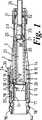
【図1】供給されたままの状態の、発射機構を取りつけていない注射装置の軸を含む断面である。
【図2】注射装置の部分の詳細斜視図である。
【図3】発射機構を取りつけて使用の準備が整った装置の軸を含む断面である。
【図4】発射機構を取りつけた注射中の装置の、軸を含む断面である。
【図5】注射後の装置の軸を含む断面である。
【図6】発射機構を取りはずして、アダプターを取りつけ、廃棄の準備のできた装置の、軸を含む断面である。
【図7】注射装置の付属品となるバイアルアダプターと、バイアルとの、軸を含む断面である。
【符号の説明】
【0036】
1 バレル
2バレルの前部
3バレルの後部
4 コネクター
5コネクターの後端部
6 肩
7 肩
8コネクターの前端部
9 戻り止め
10 スロット
11 フィンガー
12 ラグ
13 スプライン
14 ガイド手段
15 接触部分
16 固定リング
17 スナップばめのリブと溝の構成
18 肩
19 タング
20 戻り止め
21 注射器
22 カプセル
23 針ユニット
23A 針
24 キャップ
25 注射器キャリヤー
26 リム
27 戻り止め
28 フランジ
29 フランジ
30 ばね手段
31 ガイド成形物
32 ノーズピース
33 開口
34 固定部材
35 ステム
36 直交部材
37 発射装置
38 トリガーボタン
39 発射部材
40 アダプター
41 バイアル
42 ネック
43 カップ
44 環状溝
45 リブ
46 カップ
47 底
48 中心開口
49 スピゴット
50 スピゴット[0001]
The present invention relates to an injection device.
[0002]
After injection, the needled syringe is discarded in a guarded container for safety. However, removing the syringe from a reusable device that first fires the syringe forward to penetrate the needle, then pushes the syringe piston forward to eject the dose, and finally retracts the syringe and needle is It is dangerous and time consuming.
[0003]
One answer is to discard everything, but such injection devices are complex and expensive. This is therefore not a practical choice.
[0004]
However, the device is manufactured in two parts, one part being a reusable firing mechanism with a plunger that can be released and springed forward, the other part being a firing mechanism. If the housing and guide for the syringe can be temporarily mounted, the latter part can be discarded (while the syringe is housed).
[0005]
It is also useful to know at a glance whether or not the device has been used and to have some safety measures to actively prevent needle sticking before and after use.
[0006]
The object of the present invention is to provide such an apparatus.
[0007]
According to one aspect of the present invention, an injection device comprising a barrel, a syringe carrier in the barrel, spring means, and a connector, wherein thesyringe carrier is held by the syringe carrier, the syringe needle being and a rear position, as drawn into the frontof the barrel, between a forward position where the needle protrudes from the frontportion of the barrel is axially movable, said spring means the rear of thesyringe carrier Pushing toward position, the connector has limited axial freedom of movement at the rear end of the barrel for attachment of the firing device, and when the firing member of the firing device is released, the syringe In an injection device that acts on an internal piston to push the syringe forward and then injects the administered drug, at least one of a connector and a syringe carrier First, is kept immovable with respect to the barrel by a fixingmember removable inserted laterally into the barrel, when the barrel is held against the skin by the firing device is pushed forward, the removal of the fixingmember , connector and the syringe carrier may take a configuration in which thesyringe carrier and the syringe is pushed forward by actuation of the firing device, the syringe carrier is, after pulling away the injection device from the skin, in the rear position under the action of the spring means An injection device is provided that is characterized by returning.
[0008]
As can be seen from the above, this injection device is clearly unusable as long as the fixingmember is in place. If the securingmember has been removed, it indicates that the injection device has been used and should be discarded. Of course, this is not just a visual signal, but primarily a physical barrier to motion.
[0009]
In order to ensure that the fixingmember cannot be replaced after use and therefore does not give the impression that it is a new injection device, preferably the detent initially engaged by the fixingmember is no longer The connector and / or the syringe carrier are each configured to cease operation at a position where the lockingmember does not match the penetrating barrel opening. The connector can snap-engage with a detent in the barrel so that the detent can be captured in a post-use position, while the spring means can push thesyringe carrier back to its fixed position. .
[0010]
Preferably, the spring means is partially compressed in the initial fixed position, so that when the fixingmember is removed, the spring means pushes the syringe carrier rearward and from a position close to the position where the tip of the needle is barely protruding. Insert further into the barrel so that the cap can be removed. At the same time, the syringe carrier can act on the connector to push it backwards but not so far that the connector is captured in the final post-use position. Conveniently, the snap engaging element on the connector is disabled by the interengagement of the syringe carrier and the connector prior to firing of the injection device, and the disengagedengaging element causes the connector to move backwards. Is to form a stop that restricts.
[0011]
After injection, the spring means acts through the syringe carrier, the syringe, and the firing member of the firing device to return the connector back to the rear capture position, changing the axial relationship between the syringe carrier and the connector, and the snap engaging element Is disengaged so that the interengagement that limits the backward movement before firing is released.
[0012]
Conveniently, the attachment of the launcher to the connector is by a mating screw so that the connector is restrained against rotation relative to the barrel.
[0013]
The connector is a stepped tube, the small-diameterrear end provides a socket for receiving the firing device, the internal forward-facing shoulder formed by the step provides a contact portion for the rear end of the syringe carrier, and when the connector is in a position after use, external rear-facing shoulder formed by the step, be to provide a contact portion for engagement with the fixed ring fitted on theedge at the back of the barrel it can.
[0014]
The syringe carrier may have a limited range of forward motion defined by the contact portion inside the barrel. This contact portion can be provided by the rear end of the guide means for keeping the syringe carrier coaxial with the barrel, against which the flange at the rear end of the syringe carrier contacts. The flange can also provide a detent that the lockingmember engages.
[0015]
What useful, the spring means coil Banetoshi engages the front end of the syringe carrier and surrounds the coil Banegahari unit and is to be reaction against the contact portion in the frontportion of the barrel.
[0016]
Preferably, frontportion of the barrel is provided with aguide moldings pointing towards the mouth therein. Theseguide moldings allow needle sticking and needle cap removal, but make it virtually impossible to insert a finger into contact with the retracting needle.
[0017]
Conveniently, the root of theguide molding provides a contact portion for the springmeans .
[0018]
The injection device is primarily intended for use with a syringe containing a two-component dosage that must be mixed immediately prior to injection. One component is a liquid (which may be just water) that is initially in the syringe, while the other component is a powder that is dispersed in or forms a solution with the liquid.
[0019]
In order that the present invention may be more fully understood, one embodiment will now be described by way of example with reference to the accompanying drawings.
[0020]
The injection device has a barrel 1, which has a
[0021]
The barrel is provided with internal guide ribsthat define guide means 14 over the majority of the
[0022]
Within the barrel 1 is a
[0023]
At the cylindrical
[0024]
The device is designed to attach to a known
[0025]
The
[0026]
The
[0027]
The injection device is then pulled apart and the springmeans 30 act to push the barrel 1 forward and move the
[0028]
Finally, the
[0029]
In this embodiment, the securing
[0030]
FIG. 7 shows a
[0031]
Vial 41 has a
[0032]
The
[0033]
The combined
[0034]
Instead of the
[Brief description of the drawings]
[0035]
FIG. 1 is a cross-section including the shaft of an injection device with no firing mechanism, as delivered.
FIG. 2 is a detailed perspective view of a portion of the injection device.
FIG. 3 is a cross-section including the axis of the device with the firing mechanism installed and ready for use.
FIG. 4 is a cross-section including the shaft of the device during injection with the firing mechanism attached.
FIG. 5 is a cross section including the shaft of the device after injection.
FIG. 6 is a cross-section, including the shaft, of the device with the firing mechanism removed, the adapter installed and ready for disposal.
FIG. 7 is a cross-section including a shaft of a vial adapter that is an accessory of an injection device and a vial.
[Explanation of symbols]
[0036]
1 barrel
2Front of barrel
3
5Rear end of connector
6 shoulder
7 shoulder
8Front end of connector
9 Detent
10 slots
11 fingers
12 rugs
13 Spline
14 Guide means
15 Contact area
16 Fixing ring
17 Snap fit rib and groove configuration
18 shoulder
19 tongue
20
22 capsules
23
24
26 Rim
27 Detent
28 Flange
29
31 Guide molding
32 Nosepiece
33
35 stem
36
38 Trigger button
39 firing
42 neck
43 cups
44 annular groove
45 ribs
46 cups
47 Bottom
48 Center opening
49 Spigot
50 Spigot
Claims (17)
Translated fromJapanese注射器キャリヤー(25)によって保持される注射器(21)の針(23A)が前記バレル(1)の前部(2)内に引き込まれている後方位置と、前記針(23A)が前記バレル(1)の前部(2)から突き出ている前方位置との間で、軸方向に移動可能である、バレル(1)内にある注射器キャリヤー(25)と、
皮膚から注射装置を除去した後、注射器キャリヤー(25)が前記後方位置に戻るように促すばね手段(30)と、
早すぎる作動を防ぐ為に注射装置内に横方向に挿入される取り外し可能な固定部材(34)と、
から成る注射装置であって、
限られた軸方向運動の自由度を有するコネクター(4)がバレルの後部(3)に、発射装置(37)の取り付けと取り外しの為に、備えられ、前記発射装置の発射部材が、解放されると、注射器(21)内のピストンに作用して注射器を前方に促し、そして投与薬を射出し、
固定部材(34)の取り外しにより、バレル(1)に対して不動に保たれている、コネクター(4)と注射器キャリヤー(25)のうち少なくとのも一つが解放され、発射装置(37)が前方に押されることによりバレル(1)が皮膚に押し付けられて保持された時、コネクター(4)と注射器キャリヤー(25)が、該キャリヤー(25)とその注射器(21)が発射装置(37)の作動により前方に推進される配置をとる、
ことを特徴とする注射装置。Barrel (1),
The rear position where the needle (23A) of the syringe (21) held by the syringe carrier (25) is retracted into the front part (2) of the barrel (1), and the needle (23A) is the barrel (1) A syringe carrier (25) in the barrel (1) that is axially movable between a forward position protruding from the front (2) of
Spring means (30) for urging the syringe carrier (25) to return to the rearward position after removing the injection device from the skin;
A removable securing member (34) that is inserted laterally into the injection device to prevent premature actuation;
An injection device comprising:
A connector (4) with limited axial freedom of freedom is provided at the rear (3) of the barrel for the attachment and removal of the launcher (37), the launcher firing member being released. Then, it acts on the piston in the syringe (21) to urge the syringe forward, and to inject the administration drug,
Removal of the securing member (34) releases at least one of the connector (4) and the syringe carrier (25), which is held stationary relative to the barrel (1), and the firing device (37) When the barrel (1) is pressed against the skin and held by being pushed forward, the connector (4) and the syringe carrier (25) are connected to the carrier (25) and its syringe (21) to the firing device (37). Takes an arrangement propelled forward by the operation of
An injection device characterized by that.
Applications Claiming Priority (5)
| Application Number | Priority Date | Filing Date | Title |
|---|---|---|---|
| GBGB9717578.0AGB9717578D0 (en) | 1997-08-21 | 1997-08-21 | Improvements relating to injection devices |
| GB9717578.0 | 1997-08-21 | ||
| GBGB9718221.6AGB9718221D0 (en) | 1997-08-29 | 1997-08-29 | Improvements relating to injection devices |
| GB9718221.6 | 1997-08-29 | ||
| PCT/GB1998/002495WO1999010030A2 (en) | 1997-08-21 | 1998-08-20 | Improvements relating to injection devices |
Publications (3)
| Publication Number | Publication Date |
|---|---|
| JP2001513405A JP2001513405A (en) | 2001-09-04 |
| JP2001513405A5 JP2001513405A5 (en) | 2006-01-05 |
| JP4162377B2true JP4162377B2 (en) | 2008-10-08 |
Family
ID=26312091
Family Applications (1)
| Application Number | Title | Priority Date | Filing Date |
|---|---|---|---|
| JP2000507418AExpired - LifetimeJP4162377B2 (en) | 1997-08-21 | 1998-08-20 | Improvements regarding injection devices |
Country Status (12)
| Country | Link |
|---|---|
| US (1) | US6656163B1 (en) |
| EP (1) | EP1003580B1 (en) |
| JP (1) | JP4162377B2 (en) |
| AT (1) | ATE252399T1 (en) |
| AU (1) | AU737420B2 (en) |
| CA (1) | CA2300930C (en) |
| DE (1) | DE69819161T2 (en) |
| DK (1) | DK1003580T3 (en) |
| ES (1) | ES2210799T3 (en) |
| IL (1) | IL134415A (en) |
| PT (1) | PT1003580E (en) |
| WO (1) | WO1999010030A2 (en) |
Families Citing this family (106)
| Publication number | Priority date | Publication date | Assignee | Title |
|---|---|---|---|---|
| US6673035B1 (en) | 1999-10-22 | 2004-01-06 | Antares Pharma, Inc. | Medical injector and medicament loading system for use therewith |
| JP4236842B2 (en)* | 1999-10-22 | 2009-03-11 | アンタレス・ファーマ・インコーポレーテッド | Medical syringe and drug loading system used therewith |
| FR2833686B1 (en)* | 2001-12-18 | 2004-01-23 | Prospection & Inventions | COMPRESSOR GAS CARTRIDGE CONNECTION AND FIXING DEVICE |
| WO2003068290A2 (en) | 2002-02-11 | 2003-08-21 | Antares Pharma, Inc. | Intradermal injector |
| GB2410188B (en)* | 2004-01-23 | 2006-01-25 | Medical House Plc | Injection device |
| GB2414403B (en) | 2004-05-28 | 2009-01-07 | Cilag Ag Int | Injection device |
| GB2414405B (en) | 2004-05-28 | 2009-01-14 | Cilag Ag Int | Injection device |
| GB2414406B (en) | 2004-05-28 | 2009-03-18 | Cilag Ag Int | Injection device |
| GB2414400B (en) | 2004-05-28 | 2009-01-14 | Cilag Ag Int | Injection device |
| GB2414775B (en) | 2004-05-28 | 2008-05-21 | Cilag Ag Int | Releasable coupling and injection device |
| GB2414402B (en) | 2004-05-28 | 2009-04-22 | Cilag Ag Int | Injection device |
| GB2414409B (en) | 2004-05-28 | 2009-11-18 | Cilag Ag Int | Injection device |
| GB2414401B (en)* | 2004-05-28 | 2009-06-17 | Cilag Ag Int | Injection device |
| GB2414399B (en) | 2004-05-28 | 2008-12-31 | Cilag Ag Int | Injection device |
| GB2414404B (en) | 2004-05-28 | 2009-06-03 | Cilag Ag Int | Injection device |
| US7294119B2 (en)* | 2004-06-10 | 2007-11-13 | Safety Syringes, Inc. | Passive delivery system diluents mixing and delivery |
| GB0414054D0 (en) | 2004-06-23 | 2004-07-28 | Owen Mumford Ltd | Improvements relating to automatic injection devices |
| GB0418389D0 (en)* | 2004-08-18 | 2004-09-22 | Liversidge Barry P | Injection apparatus |
| WO2006057636A1 (en) | 2004-11-22 | 2006-06-01 | Intelliject, Llc | Devices, systems, and methods for medicament delivery |
| US10737028B2 (en) | 2004-11-22 | 2020-08-11 | Kaleo, Inc. | Devices, systems and methods for medicament delivery |
| US7648483B2 (en) | 2004-11-22 | 2010-01-19 | Intelliject, Inc. | Devices, systems and methods for medicament delivery |
| US11590286B2 (en) | 2004-11-22 | 2023-02-28 | Kaleo, Inc. | Devices, systems and methods for medicament delivery |
| HUE042286T2 (en) | 2005-01-24 | 2019-06-28 | Antares Pharma Inc | Needle-filled pre-filled syringe |
| AU2006210865B2 (en) | 2005-02-01 | 2008-12-04 | Kaleo, Inc. | Devices, systems, and methods for medicament delivery |
| GB2424836B (en) | 2005-04-06 | 2010-09-22 | Cilag Ag Int | Injection device (bayonet cap removal) |
| GB2425062B (en) | 2005-04-06 | 2010-07-21 | Cilag Ag Int | Injection device |
| GB2424835B (en) | 2005-04-06 | 2010-06-09 | Cilag Ag Int | Injection device (modified trigger) |
| GB2424838B (en) | 2005-04-06 | 2011-02-23 | Cilag Ag Int | Injection device (adaptable drive) |
| GB2427826B (en) | 2005-04-06 | 2010-08-25 | Cilag Ag Int | Injection device comprising a locking mechanism associated with integrally formed biasing means |
| FR2884896B1 (en)* | 2005-04-26 | 2007-06-29 | Prospection Et D Inv S Techniq | SEALING CONNECTION AND ASSEMBLY OF A TRANSMISSION MEMBER, A GAS CARTRIDGE AND AN ADAPTER COMPRISING THE CONNECTION |
| PL1759729T3 (en) | 2005-08-30 | 2010-09-30 | Cilag Gmbh Int | Needle assembly for a prefilled syringe system |
| US20110098656A1 (en) | 2005-09-27 | 2011-04-28 | Burnell Rosie L | Auto-injection device with needle protecting cap having outer and inner sleeves |
| GB0601309D0 (en) | 2006-01-23 | 2006-03-01 | Medical House The Plc | Injection device |
| US20070173770A1 (en)* | 2006-01-23 | 2007-07-26 | The Medical House Plc | Injection device |
| WO2007131013A1 (en) | 2006-05-03 | 2007-11-15 | Antares Pharma, Inc. | Two-stage reconstituting injector |
| US7811252B2 (en) | 2006-05-17 | 2010-10-12 | Alcon Research, Ltd. | Dosage control device |
| GB2438591B (en) | 2006-06-01 | 2011-07-13 | Cilag Gmbh Int | Injection device |
| GB2438593B (en) | 2006-06-01 | 2011-03-30 | Cilag Gmbh Int | Injection device (cap removal feature) |
| GB2438590B (en) | 2006-06-01 | 2011-02-09 | Cilag Gmbh Int | Injection device |
| KR101396797B1 (en) | 2006-06-30 | 2014-05-26 | 애브비 바이오테크놀로지 리미티드 | Automatic injection device |
| GB0625169D0 (en) | 2006-12-18 | 2007-01-24 | Medical House Plc The | Improved autoinjector |
| GB0704351D0 (en)* | 2007-03-07 | 2007-04-11 | Medical House Plc The | Improved autoinjector |
| US9044378B2 (en)* | 2007-05-31 | 2015-06-02 | Safety Syringes, Inc. | Anti-needle stick safety device or system for use with drugs requiring reconstitution |
| GB2451662B (en) | 2007-08-08 | 2012-09-19 | Cilag Gmbh Int | Injection device |
| GB2451666B (en)* | 2007-08-08 | 2012-08-22 | Cilag Gmbh Int | Injection device |
| GB2451664B (en)* | 2007-08-08 | 2012-06-20 | Cilag Gmbh Int | Injection device |
| GB2452030A (en)* | 2007-08-10 | 2009-02-25 | Owen Mumford Ltd | Injection devices |
| US8105292B2 (en) | 2008-02-11 | 2012-01-31 | Safety Syringes, Inc. | Reconstitution means for safety device |
| US8052645B2 (en) | 2008-07-23 | 2011-11-08 | Avant Medical Corp. | System and method for an injection using a syringe needle |
| CA3070618C (en) | 2008-05-20 | 2021-07-20 | Avant Medical Corp. | Autoinjector system |
| US8177749B2 (en)* | 2008-05-20 | 2012-05-15 | Avant Medical Corp. | Cassette for a hidden injection needle |
| GB2461086B (en) | 2008-06-19 | 2012-12-05 | Cilag Gmbh Int | Injection device |
| GB2461089B (en) | 2008-06-19 | 2012-09-19 | Cilag Gmbh Int | Injection device |
| GB2461084B (en) | 2008-06-19 | 2012-09-26 | Cilag Gmbh Int | Fluid transfer assembly |
| GB2461085B (en) | 2008-06-19 | 2012-08-29 | Cilag Gmbh Int | Injection device |
| GB2461087B (en) | 2008-06-19 | 2012-09-26 | Cilag Gmbh Int | Injection device |
| US8376993B2 (en) | 2008-08-05 | 2013-02-19 | Antares Pharma, Inc. | Multiple dosage injector |
| USD619799S1 (en)* | 2008-12-23 | 2010-07-20 | Bayer Schering Pharma Ag | Pill dispenser |
| GT200900043S (en)* | 2008-12-23 | 2010-11-17 | PILL DISPENSER | |
| GB0900930D0 (en) | 2009-01-20 | 2009-03-04 | Future Injection Technologies Ltd | Injection device |
| KR101366427B1 (en) | 2009-03-13 | 2014-02-24 | 일라이 릴리 앤드 캄파니 | Apparatus for injecting a pharmaceutical with automatic syringe retraction following injection |
| JP5732039B2 (en) | 2009-03-20 | 2015-06-10 | アンタレス・ファーマ・インコーポレーテッド | Hazardous drug injection system |
| GB2469672B (en) | 2009-04-23 | 2013-09-25 | Medical House Ltd | Improved autoinjector |
| WO2010127146A1 (en) | 2009-04-29 | 2010-11-04 | Abbott Biotechnology Ltd | Automatic injection device |
| CL2010000294E1 (en) | 2009-09-30 | 2011-07-29 | Bayer Schering Pharma Ag | Industrial graphic interface drawing of a tablet dispenser that has three circular elements and three horizontal lines next to each circumference, which is composed of an ellipse and next to it a vertical line with two angled lines, are projected horizontally aligned series of correlative numbers from 1 to number 4, inscribed within a rectangle, crossed by a diagonal line. |
| WO2011039213A2 (en)* | 2009-09-30 | 2011-04-07 | Sanofi-Aventis Deutschland Gmbh | An assembly of a drug delivery device |
| CR11338S (en) | 2009-09-30 | 2010-09-08 | Bayer Schering Pharma Ag | PILL DISPENSER (DISPLAY) |
| US9358340B2 (en)* | 2009-09-30 | 2016-06-07 | Sanofi-Aventis Deutschland Gmbh | Method and assembly for a drug delivery device |
| EP2512558A4 (en) | 2009-12-15 | 2014-08-13 | Abbvie Biotechnology Ltd | IMPROVED TRIP PUSHER FOR AUTOMATIC INJECTION DEVICE |
| USD657131S1 (en) | 2010-03-30 | 2012-04-10 | Bayer Schering Pharma Ag | Portion of a display screen for a pill dispenser |
| NZ702172A (en) | 2010-04-21 | 2016-03-31 | Abbvie Biotechnology Ltd | Wearable automatic injection device for controlled delivery of therapeutic agents |
| KR101989342B1 (en) | 2011-01-24 | 2019-06-14 | 애브비 바이오테크놀로지 리미티드 | Removal of needle shields from syringes and automatic injection devices |
| BR112013018905B1 (en) | 2011-01-24 | 2021-07-13 | Abbvie Biotechnology Ltd | AUTOMATIC INJECTION DEVICES THAT HAVE OVERMOLDED HANDLE SURFACES. |
| ES2710905T3 (en) | 2011-01-24 | 2019-04-29 | E3D Agricultural Coop Association Ltd | Injector |
| US9173999B2 (en) | 2011-01-26 | 2015-11-03 | Kaleo, Inc. | Devices and methods for delivering medicaments from a multi-chamber container |
| PL2699293T3 (en) | 2011-04-20 | 2019-08-30 | Amgen Inc. | Autoinjector apparatus |
| US8496619B2 (en) | 2011-07-15 | 2013-07-30 | Antares Pharma, Inc. | Injection device with cammed ram assembly |
| US9220660B2 (en) | 2011-07-15 | 2015-12-29 | Antares Pharma, Inc. | Liquid-transfer adapter beveled spike |
| EP2601992A1 (en) | 2011-12-08 | 2013-06-12 | Sanofi-Aventis Deutschland GmbH | Syringe carrier |
| EP4186545A1 (en) | 2012-04-06 | 2023-05-31 | Antares Pharma, Inc. | Needle assisted jet injection administration of testosterone compositions |
| US9415172B2 (en) | 2012-04-19 | 2016-08-16 | Ultimed, Inc. | Safety syringe and needle shield |
| USD808010S1 (en) | 2012-04-20 | 2018-01-16 | Amgen Inc. | Injection device |
| USD898908S1 (en) | 2012-04-20 | 2020-10-13 | Amgen Inc. | Pharmaceutical product cassette for an injection device |
| US9364610B2 (en) | 2012-05-07 | 2016-06-14 | Antares Pharma, Inc. | Injection device with cammed ram assembly |
| US9522235B2 (en) | 2012-05-22 | 2016-12-20 | Kaleo, Inc. | Devices and methods for delivering medicaments from a multi-chamber container |
| FI3659647T3 (en) | 2013-02-11 | 2024-03-28 | Antares Pharma Inc | NEEDLE-ASSISTED SPRAY INJECTOR WITH REDUCED TRIGGER FORCE |
| US9604184B2 (en) | 2013-03-06 | 2017-03-28 | Orthovita, Inc. | Mixing system and valve assembly |
| CA2905031C (en) | 2013-03-11 | 2018-01-23 | Hans PFLAUMER | Dosage injector with pinion system |
| EP2777684A1 (en) | 2013-03-14 | 2014-09-17 | Sanofi-Aventis Deutschland GmbH | Medicament container carrier and adapter |
| CA2904661C (en) | 2013-03-15 | 2022-03-15 | Amgen Inc. | Drug cassette, autoinjector, and autoinjector system |
| ES2973257T3 (en) | 2013-03-15 | 2024-06-19 | Amgen Inc | Drug cassette, autoinjector and autoinjector system |
| GB2515032A (en) | 2013-06-11 | 2014-12-17 | Cilag Gmbh Int | Guide for an injection device |
| GB2515038A (en) | 2013-06-11 | 2014-12-17 | Cilag Gmbh Int | Injection device |
| GB2515039B (en) | 2013-06-11 | 2015-05-27 | Cilag Gmbh Int | Injection Device |
| GB2517896B (en) | 2013-06-11 | 2015-07-08 | Cilag Gmbh Int | Injection device |
| CA3009221A1 (en) | 2014-12-23 | 2016-06-30 | Automed Pty Ltd | Delivery apparatus, system and associated methods |
| US10695495B2 (en) | 2015-03-24 | 2020-06-30 | Kaleo, Inc. | Devices and methods for delivering a lyophilized medicament |
| TW201705994A (en) | 2015-06-03 | 2017-02-16 | 賽諾菲阿凡提斯德意志有限公司 | Automatic syringe and assembly method |
| TW201700117A (en) | 2015-06-03 | 2017-01-01 | 賽諾菲阿凡提斯德意志有限公司 | Syringe bracket and assembly method for autoinjector |
| CA2990950A1 (en) | 2015-06-30 | 2017-01-05 | Kaleo, Inc. | Auto-injectors for administration of a medicament within a prefilled syringe |
| WO2018119218A1 (en) | 2016-12-23 | 2018-06-28 | Kaleo, Inc. | Medicament delivery device and methods for delivering drugs to infants and children |
| NZ767760A (en)* | 2017-01-20 | 2025-07-25 | L G P Tech Holdings Llc | Auto-injector device |
| CN109745597B (en)* | 2019-03-08 | 2021-02-05 | 上海久正医用包装材料有限公司 | Prefilled syringe |
| CA3145580A1 (en) | 2019-08-09 | 2021-02-18 | Kaleo, Inc. | Devices and methods for delivery of substances within a prefilled syringe |
| US11957542B2 (en) | 2020-04-30 | 2024-04-16 | Automed Patent Holdco, Llc | Sensing complete injection for animal injection device |
| US12268847B1 (en) | 2021-02-10 | 2025-04-08 | Kaleo, Inc. | Devices and methods for delivery of substances within a medicament container |
Family Cites Families (14)
| Publication number | Priority date | Publication date | Assignee | Title |
|---|---|---|---|---|
| FR1257066A (en)* | 1960-02-13 | 1961-03-31 | Automatic auto-injector | |
| US4493348A (en)* | 1981-06-29 | 1985-01-15 | Pur/Acc Corporation | Method and apparatus for orally dispensing liquid medication |
| US4507113A (en) | 1982-11-22 | 1985-03-26 | Derata Corporation | Hypodermic jet injector |
| US4662878A (en)* | 1985-11-13 | 1987-05-05 | Patents Unlimited Ltd. | Medicine vial adaptor for needleless injector |
| DE3715340C2 (en)* | 1987-05-08 | 1995-10-19 | Haselmeier Wilhelm Fa | Injection device |
| GB8819977D0 (en)* | 1988-08-23 | 1988-09-21 | Medimech Ltd | Automatic injectors |
| US5171214A (en)* | 1990-12-26 | 1992-12-15 | Abbott Laboratories | Drug storage and delivery system |
| GB9200219D0 (en)* | 1992-01-07 | 1992-02-26 | Medimech Int Ltd | Automatic injectors |
| US5681291A (en)* | 1992-11-19 | 1997-10-28 | Tebro S.A. | Disposable auto-injector for prefilled syringes |
| EP0693946B1 (en)* | 1993-03-24 | 2001-05-16 | Owen Mumford Limited | Improvements relating to injection devices |
| US5478316A (en)* | 1994-02-02 | 1995-12-26 | Becton, Dickinson And Company | Automatic self-injection device |
| ATE225197T1 (en)* | 1994-05-30 | 2002-10-15 | B D Medico S A R L | INJECTION DEVICE |
| FR2733155B1 (en)* | 1995-04-18 | 1997-09-19 | Tebro | RECHARGEABLE SELF-INJECTOR |
| US5609577A (en)* | 1996-01-29 | 1997-03-11 | Haber; Terry M. | Automatically locking hypodermic needle hiding shield for a dose metering syringe |
- 1998
- 1998-08-20ESES98939757Tpatent/ES2210799T3/ennot_activeExpired - Lifetime
- 1998-08-20PTPT98939757Tpatent/PT1003580E/enunknown
- 1998-08-20CACA002300930Apatent/CA2300930C/ennot_activeExpired - Lifetime
- 1998-08-20JPJP2000507418Apatent/JP4162377B2/ennot_activeExpired - Lifetime
- 1998-08-20USUS09/486,079patent/US6656163B1/ennot_activeExpired - Lifetime
- 1998-08-20DKDK98939757Tpatent/DK1003580T3/enactive
- 1998-08-20EPEP98939757Apatent/EP1003580B1/ennot_activeExpired - Lifetime
- 1998-08-20WOPCT/GB1998/002495patent/WO1999010030A2/enactiveIP Right Grant
- 1998-08-20ATAT98939757Tpatent/ATE252399T1/enactive
- 1998-08-20ILIL13441598Apatent/IL134415A/ennot_activeIP Right Cessation
- 1998-08-20DEDE69819161Tpatent/DE69819161T2/ennot_activeExpired - Lifetime
- 1998-08-20AUAU88163/98Apatent/AU737420B2/ennot_activeExpired
Also Published As
| Publication number | Publication date |
|---|---|
| JP2001513405A (en) | 2001-09-04 |
| DE69819161D1 (en) | 2003-11-27 |
| ATE252399T1 (en) | 2003-11-15 |
| PT1003580E (en) | 2004-01-30 |
| US6656163B1 (en) | 2003-12-02 |
| ES2210799T3 (en) | 2004-07-01 |
| DK1003580T3 (en) | 2004-02-23 |
| EP1003580B1 (en) | 2003-10-22 |
| DE69819161T2 (en) | 2004-07-08 |
| CA2300930C (en) | 2007-10-16 |
| CA2300930A1 (en) | 1999-03-04 |
| IL134415A (en) | 2004-01-04 |
| EP1003580A2 (en) | 2000-05-31 |
| AU8816398A (en) | 1999-03-16 |
| WO1999010030A3 (en) | 1999-05-20 |
| AU737420B2 (en) | 2001-08-16 |
| WO1999010030A2 (en) | 1999-03-04 |
| IL134415A0 (en) | 2001-04-30 |
Similar Documents
| Publication | Publication Date | Title |
|---|---|---|
| JP4162377B2 (en) | Improvements regarding injection devices | |
| JP4049994B2 (en) | Improvements regarding injection devices | |
| US5085638A (en) | Single use disposable syringe | |
| EP0272035B1 (en) | Injection device | |
| JP3168179B2 (en) | Injection equipment | |
| JP5721849B2 (en) | Drug delivery device | |
| EP0814858B1 (en) | Improvements relating to medical injection devices | |
| US12121708B2 (en) | Safety housing based implant/medicament injecting system | |
| CA2365576C (en) | Safety syringe | |
| JP2006507061A (en) | Automatic injection device with resettable release safety device | |
| US20050101919A1 (en) | Device for an injector | |
| JP5721850B2 (en) | Drug delivery device | |
| JPS61500774A (en) | Two-way auto-injector | |
| KR20130118969A (en) | Medicament delivery device | |
| IL104263A (en) | Automatic injectors | |
| AU1435801A (en) | Medical injector and medicament loading system for use therewith | |
| CA2574298C (en) | Syringe | |
| CN114728128B (en) | Container holder assembly for a medicament delivery device and medicament delivery device | |
| TWI880638B (en) | Injection device with an improved needle guard lockout mechanism | |
| TWI867967B (en) | Injection device with an improved triggering mechanism | |
| WO2025032486A1 (en) | Injection device with an improved mechanism for generating an audible feedback | |
| JP2025532220A (en) | Emergency auto-injector | |
| CZ208196A3 (en) | Safety syringe with retractable needle without sealing ring |
Legal Events
| Date | Code | Title | Description |
|---|---|---|---|
| A521 | Request for written amendment filed | Free format text:JAPANESE INTERMEDIATE CODE: A523 Effective date:20050513 | |
| A621 | Written request for application examination | Free format text:JAPANESE INTERMEDIATE CODE: A621 Effective date:20050513 | |
| RD02 | Notification of acceptance of power of attorney | Free format text:JAPANESE INTERMEDIATE CODE: A7422 Effective date:20070525 | |
| A131 | Notification of reasons for refusal | Free format text:JAPANESE INTERMEDIATE CODE: A131 Effective date:20070529 | |
| A131 | Notification of reasons for refusal | Free format text:JAPANESE INTERMEDIATE CODE: A131 Effective date:20070911 | |
| A601 | Written request for extension of time | Free format text:JAPANESE INTERMEDIATE CODE: A601 Effective date:20071207 | |
| A602 | Written permission of extension of time | Free format text:JAPANESE INTERMEDIATE CODE: A602 Effective date:20071214 | |
| A601 | Written request for extension of time | Free format text:JAPANESE INTERMEDIATE CODE: A601 Effective date:20080111 | |
| A602 | Written permission of extension of time | Free format text:JAPANESE INTERMEDIATE CODE: A602 Effective date:20080121 | |
| A521 | Request for written amendment filed | Free format text:JAPANESE INTERMEDIATE CODE: A523 Effective date:20080212 | |
| A131 | Notification of reasons for refusal | Free format text:JAPANESE INTERMEDIATE CODE: A131 Effective date:20080311 | |
| A521 | Request for written amendment filed | Free format text:JAPANESE INTERMEDIATE CODE: A523 Effective date:20080606 | |
| TRDD | Decision of grant or rejection written | ||
| A01 | Written decision to grant a patent or to grant a registration (utility model) | Free format text:JAPANESE INTERMEDIATE CODE: A01 Effective date:20080708 | |
| A01 | Written decision to grant a patent or to grant a registration (utility model) | Free format text:JAPANESE INTERMEDIATE CODE: A01 | |
| A61 | First payment of annual fees (during grant procedure) | Free format text:JAPANESE INTERMEDIATE CODE: A61 Effective date:20080722 | |
| FPAY | Renewal fee payment (event date is renewal date of database) | Free format text:PAYMENT UNTIL: 20110801 Year of fee payment:3 | |
| R150 | Certificate of patent or registration of utility model | Free format text:JAPANESE INTERMEDIATE CODE: R150 | |
| FPAY | Renewal fee payment (event date is renewal date of database) | Free format text:PAYMENT UNTIL: 20110801 Year of fee payment:3 | |
| FPAY | Renewal fee payment (event date is renewal date of database) | Free format text:PAYMENT UNTIL: 20120801 Year of fee payment:4 | |
| FPAY | Renewal fee payment (event date is renewal date of database) | Free format text:PAYMENT UNTIL: 20130801 Year of fee payment:5 | |
| R250 | Receipt of annual fees | Free format text:JAPANESE INTERMEDIATE CODE: R250 | |
| R250 | Receipt of annual fees | Free format text:JAPANESE INTERMEDIATE CODE: R250 | |
| R250 | Receipt of annual fees | Free format text:JAPANESE INTERMEDIATE CODE: R250 | |
| R250 | Receipt of annual fees | Free format text:JAPANESE INTERMEDIATE CODE: R250 | |
| R250 | Receipt of annual fees | Free format text:JAPANESE INTERMEDIATE CODE: R250 | |
| R250 | Receipt of annual fees | Free format text:JAPANESE INTERMEDIATE CODE: R250 | |
| EXPY | Cancellation because of completion of term |