JP4157574B2 - Surgical instrument - Google Patents
Surgical instrumentDownload PDFInfo
- Publication number
- JP4157574B2 JP4157574B2JP2006184663AJP2006184663AJP4157574B2JP 4157574 B2JP4157574 B2JP 4157574B2JP 2006184663 AJP2006184663 AJP 2006184663AJP 2006184663 AJP2006184663 AJP 2006184663AJP 4157574 B2JP4157574 B2JP 4157574B2
- Authority
- JP
- Japan
- Prior art keywords
- gripping
- gripping member
- electrode
- electrode portion
- ultrasonic
- Prior art date
- Legal status (The legal status is an assumption and is not a legal conclusion. Google has not performed a legal analysis and makes no representation as to the accuracy of the status listed.)
- Active
Links
Images


Classifications
- A—HUMAN NECESSITIES
- A61—MEDICAL OR VETERINARY SCIENCE; HYGIENE
- A61B—DIAGNOSIS; SURGERY; IDENTIFICATION
- A61B18/00—Surgical instruments, devices or methods for transferring non-mechanical forms of energy to or from the body
- A61B18/04—Surgical instruments, devices or methods for transferring non-mechanical forms of energy to or from the body by heating
- A61B18/12—Surgical instruments, devices or methods for transferring non-mechanical forms of energy to or from the body by heating by passing a current through the tissue to be heated, e.g. high-frequency current
- A61B18/14—Probes or electrodes therefor
- A61B18/1442—Probes having pivoting end effectors, e.g. forceps
- A61B18/1445—Probes having pivoting end effectors, e.g. forceps at the distal end of a shaft, e.g. forceps or scissors at the end of a rigid rod
- A—HUMAN NECESSITIES
- A61—MEDICAL OR VETERINARY SCIENCE; HYGIENE
- A61B—DIAGNOSIS; SURGERY; IDENTIFICATION
- A61B17/00—Surgical instruments, devices or methods
- A61B17/32—Surgical cutting instruments
- A61B17/320068—Surgical cutting instruments using mechanical vibrations, e.g. ultrasonic
- A61B17/320092—Surgical cutting instruments using mechanical vibrations, e.g. ultrasonic with additional movable means for clamping or cutting tissue, e.g. with a pivoting jaw
- A—HUMAN NECESSITIES
- A61—MEDICAL OR VETERINARY SCIENCE; HYGIENE
- A61B—DIAGNOSIS; SURGERY; IDENTIFICATION
- A61B18/00—Surgical instruments, devices or methods for transferring non-mechanical forms of energy to or from the body
- A61B18/04—Surgical instruments, devices or methods for transferring non-mechanical forms of energy to or from the body by heating
- A61B18/12—Surgical instruments, devices or methods for transferring non-mechanical forms of energy to or from the body by heating by passing a current through the tissue to be heated, e.g. high-frequency current
- A61B18/14—Probes or electrodes therefor
- A61B18/16—Indifferent or passive electrodes for grounding
- A—HUMAN NECESSITIES
- A61—MEDICAL OR VETERINARY SCIENCE; HYGIENE
- A61B—DIAGNOSIS; SURGERY; IDENTIFICATION
- A61B17/00—Surgical instruments, devices or methods
- A61B17/32—Surgical cutting instruments
- A—HUMAN NECESSITIES
- A61—MEDICAL OR VETERINARY SCIENCE; HYGIENE
- A61B—DIAGNOSIS; SURGERY; IDENTIFICATION
- A61B17/00—Surgical instruments, devices or methods
- A61B17/32—Surgical cutting instruments
- A61B17/320068—Surgical cutting instruments using mechanical vibrations, e.g. ultrasonic
- A61B17/320092—Surgical cutting instruments using mechanical vibrations, e.g. ultrasonic with additional movable means for clamping or cutting tissue, e.g. with a pivoting jaw
- A61B2017/320093—Surgical cutting instruments using mechanical vibrations, e.g. ultrasonic with additional movable means for clamping or cutting tissue, e.g. with a pivoting jaw additional movable means performing cutting operation
- A—HUMAN NECESSITIES
- A61—MEDICAL OR VETERINARY SCIENCE; HYGIENE
- A61B—DIAGNOSIS; SURGERY; IDENTIFICATION
- A61B17/00—Surgical instruments, devices or methods
- A61B17/32—Surgical cutting instruments
- A61B17/320068—Surgical cutting instruments using mechanical vibrations, e.g. ultrasonic
- A61B17/320092—Surgical cutting instruments using mechanical vibrations, e.g. ultrasonic with additional movable means for clamping or cutting tissue, e.g. with a pivoting jaw
- A61B2017/320095—Surgical cutting instruments using mechanical vibrations, e.g. ultrasonic with additional movable means for clamping or cutting tissue, e.g. with a pivoting jaw with sealing or cauterizing means
- A—HUMAN NECESSITIES
- A61—MEDICAL OR VETERINARY SCIENCE; HYGIENE
- A61B—DIAGNOSIS; SURGERY; IDENTIFICATION
- A61B18/00—Surgical instruments, devices or methods for transferring non-mechanical forms of energy to or from the body
- A61B2018/00053—Mechanical features of the instrument of device
- A61B2018/00184—Moving parts
- A61B2018/0019—Moving parts vibrating
- A—HUMAN NECESSITIES
- A61—MEDICAL OR VETERINARY SCIENCE; HYGIENE
- A61B—DIAGNOSIS; SURGERY; IDENTIFICATION
- A61B18/00—Surgical instruments, devices or methods for transferring non-mechanical forms of energy to or from the body
- A61B2018/00571—Surgical instruments, devices or methods for transferring non-mechanical forms of energy to or from the body for achieving a particular surgical effect
- A61B2018/00589—Coagulation
- A—HUMAN NECESSITIES
- A61—MEDICAL OR VETERINARY SCIENCE; HYGIENE
- A61B—DIAGNOSIS; SURGERY; IDENTIFICATION
- A61B18/00—Surgical instruments, devices or methods for transferring non-mechanical forms of energy to or from the body
- A61B18/04—Surgical instruments, devices or methods for transferring non-mechanical forms of energy to or from the body by heating
- A61B18/12—Surgical instruments, devices or methods for transferring non-mechanical forms of energy to or from the body by heating by passing a current through the tissue to be heated, e.g. high-frequency current
- A61B18/14—Probes or electrodes therefor
- A61B18/1442—Probes having pivoting end effectors, e.g. forceps
- A61B2018/146—Scissors
- A—HUMAN NECESSITIES
- A61—MEDICAL OR VETERINARY SCIENCE; HYGIENE
- A61N—ELECTROTHERAPY; MAGNETOTHERAPY; RADIATION THERAPY; ULTRASOUND THERAPY
- A61N1/00—Electrotherapy; Circuits therefor
- A61N1/18—Applying electric currents by contact electrodes
- A61N1/32—Applying electric currents by contact electrodes alternating or intermittent currents
- A61N1/328—Applying electric currents by contact electrodes alternating or intermittent currents for improving the appearance of the skin, e.g. facial toning or wrinkle treatment
- A—HUMAN NECESSITIES
- A61—MEDICAL OR VETERINARY SCIENCE; HYGIENE
- A61N—ELECTROTHERAPY; MAGNETOTHERAPY; RADIATION THERAPY; ULTRASOUND THERAPY
- A61N7/00—Ultrasound therapy
- A61N7/02—Localised ultrasound hyperthermia
Landscapes
- Health & Medical Sciences (AREA)
- Surgery (AREA)
- Engineering & Computer Science (AREA)
- Life Sciences & Earth Sciences (AREA)
- Heart & Thoracic Surgery (AREA)
- Veterinary Medicine (AREA)
- Nuclear Medicine, Radiotherapy & Molecular Imaging (AREA)
- Biomedical Technology (AREA)
- Public Health (AREA)
- Medical Informatics (AREA)
- Molecular Biology (AREA)
- Animal Behavior & Ethology (AREA)
- General Health & Medical Sciences (AREA)
- Physics & Mathematics (AREA)
- Plasma & Fusion (AREA)
- Otolaryngology (AREA)
- Dentistry (AREA)
- Mechanical Engineering (AREA)
- Surgical Instruments (AREA)
Description
Translated fromJapanese本発明は、生体組織を把持した後、超音波振動と高周波電流により生体組織を凝固・切開する外科用処置具に関する。 The present invention relates to a surgical treatment instrument for coagulating and incising a living tissue by ultrasonic vibration and high-frequency current after gripping the living tissue.
外科用処置具としての超音波振動を用いる超音波処置具や高周波電流を用いる高周波処置具が知られている。超音波処置具は、超音波振動によって発熱させて生体組織を凝固・切開を行うことができる。高周波処置具は、通電されている電極を生体組織に接触させることによって凝固・切開を行うことができる。
また、超音波振動による処置と高周波電流による処置とを組合わせた外科用処置装置は、例えば、特許文献1〜3で知られている。この外科用処置装置は、操作部に設けた超音波振動子で発生した超音波振動を振動伝達部材を介して超音波プローブの先端部に伝達させると共に、この超音波プローブに対して回動自在なジョーを備え、超音波プローブとの間で生体組織を把持するようになっている。さらに、外部に設けた高周波電源から超音波プローブに高周波電流を流し、把持した生体組織に高周波電流を流して凝固・切開を行うようになっている。
Moreover, the surgical treatment apparatus which combined the process by an ultrasonic vibration and the process by a high frequency current is known by patent documents 1-3, for example. This surgical treatment apparatus transmits ultrasonic vibration generated by an ultrasonic vibrator provided in an operation unit to a distal end portion of an ultrasonic probe via a vibration transmission member, and is rotatable with respect to the ultrasonic probe. A living jaw is grasped between the ultrasonic probe and the ultrasonic probe. Further, a high frequency current is supplied from an external high frequency power source to the ultrasonic probe, and a high frequency current is supplied to the grasped living tissue to perform coagulation / incision.
しかしながら、特許文献1は、超音波振動を発生する丸棒状のホーンと、このホーンに対して開閉する断面円弧状の開閉カバーとによって生体組織を把持し、ホーンからの超音波振動と開閉カバーに設けた電極からの高周波電流によって生体組織を凝固・切開するようになっている。したがって、丸棒状のホーンと、断面円弧状の開閉カバーとによって生体組織を把持する構造であり、把持方向に沿った面部で生体組織を把持することになり、強い把持力(圧縮力)が得られないという問題がある。
特許文献2及び3は、超音波振動を発生する丸棒状のホーンと、このホーンに対して開閉する把持部材とによって生体組織を把持し、ホーンからの超音波振動と把持部材に設けた電極からの高周波電流によって生体組織を凝固・切開するようになっている。したがって、丸棒状のホーンと把持部材とで生体組織を把持する構造であり、把持部材の把持方向に対して曲面で受けて生体組織を把持することになり、強い把持力(圧縮力)が得られないという問題がある。
本発明は、前記事情に着目してなされたもので、その目的とするところは、生体組織を確実に強い把持力で把持して凝固・切開でき、処置時間を短縮できる外科用処置具を提供することにある。However, in
In
The present invention has been made paying attention to the above-mentioned circumstances, and an object thereof is to provide a surgical treatment tool that can firmly solidify and incise a living tissue with a strong gripping force and can shorten a treatment time. There is to do.
前記目的を達成するために、請求項1は、第1の把持部材と、前記第1の把持部材に対して開閉可能に設けられ、該第1の把持部材との間で生体組織を把持する第2の把持部材と、前記第1もしくは第2の把持部材の一方に設けられ、超音波振動子と接続されて超音波振動する超音波振動部と、前記第1もしくは第2の把持部材の他方に設けられ、前記超音波振動部と対向し、該超音波振動部との間で生体組織を押圧する押圧部と、前記超音波振動部と前記押圧部との間に設けられた切開面を有した超音波凝固切開手段と、前記第1の把持部材に設けられた第1電極部と、前記第2の把持部材に設けられた第2電極部と、前記第1電極部と前記第2電極部との間に設けられかつ前記切開面以外の位置に設けられた凝固面を有し、該第1電極部と前記第2電極部とを対向して設けて生体組織を凝固する高周波凝固手段と、を具備したことを特徴とする外科用処置具にある。
請求項2は、第1の把持部材と、前記第1の把持部材に対して開閉可能に設けられ、該第1の把持部材との間で生体組織を把持する第2の把持部材と、前記第1もしくは第2の把持部材の一方に設けられ、超音波振動子と接続されて超音波振動する超音波振動部と、前記第1もしくは第2の把持部材の他方に設けられ、前記超音波振動部と対向し、該超音波振動部との間で生体組織を押圧する押圧部と、前記超音波振動部と前記押圧部との間に設けられた切開面を有した超音波凝固切開手段と、前記第1の把持部材に設けられた第1電極部と、前記第2の把持部材に設けられた第2電極部と、前記第1電極部と前記第1電極部との間に設けられた凝固面を有し、第1電極部と第2電極部とを対向して設けて生体組織を凝固するとともに、前記第1と第2の把持部材との把持操作によって前記超音波凝固切開手段を構成する押圧部と前記超音波振動部とが接したとき、前記第1電極部と前記第2電極部の間に隙間を形成する位置関係にある高周波凝固手段と、を具備したことを特徴とする外科用処置具にある。
請求項3は、前記凝固面は、前記切開面以外の位置に設けられていることを特徴とする請求項2記載の外科用処置具である。
請求項4は、前記超音波凝固切開手段を構成する押圧部と超音波振動部の把持面は、凹部と凸部の組み合わせからなり、生体組織を把持したとき、生体組織が屈曲されて前記把持面に面接触することを特徴とする請求項1または2記載の外科用処置具である。
請求項5は、前記第2の把持部材は、前記第1の把持部材より左右方向の両側に張り出さない構造であることを特徴とする請求項1または2記載の外科用処置具である。In order to achieve the above object, according to a first aspect of the present invention, the first grasping member and the first grasping member are provided so as to be openable and closable, and the living tissue is grasped between the first grasping member. An ultrasonic vibration unit that is provided on one of the second gripping member and one of the first or second gripping member and is ultrasonically vibrated by being connected to an ultrasonic transducer; and the first or second gripping member A pressing portionthat is provided on the other side, faces the ultrasonic vibration portion, and presses the living tissue between theultrasonic vibration portion, and an incision surface provided between the ultrasonic vibration portion and the pressing portion; an ultrasonic coagulation and incision meanshaving a first electrode portion provided on the first grippingmember, and the second electrode portion provided in the second grippingmember, the said first electrode portion first It has asolidification surface provided on the provided and a position other than the cutting surface between the second electrode portion, the first electrode portion In surgical instrument, characterized in that anda high-frequency coagulation means for coagulating the living tissue opposed to said second electrode portions.
The surgical treatment tool according to
According to a fourthaspect of the present invention, the gripping surfaces of the pressing part and the ultrasonic vibration part constituting the ultrasonic coagulation / cutting means are a combination of a concave part and a convex part, and when the biological tissue is gripped, the biological tissue is bent and the gripping is performed The surgical instrument according to
According to a fifth aspect of the presentinvention, in the surgical treatment tool according to the first or second aspect,the second gripping member has a structure that does not protrude from both sides in the left-right direction from the first gripping member .
本発明によれば、第1と第2の把持部材とで生体組織を把持した際に強い把持力が得られ、目的部位を確実に凝固・切開でき、処置時間を短縮できるという効果がある。 According to the present invention, a strong grasping force can be obtained when a living tissue is grasped by the first and second grasping members, and the target site can be reliably coagulated / incised, and the treatment time can be shortened.
以下、図面を参照して本発明の実施の形態を説明する。 Embodiments of the present invention will be described below with reference to the drawings.
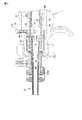
図1〜図8は、第1の実施形態を示し、図1は外科用処置具としての超音波処置具の全体構成図である。図1に示すように、超音波処置具10は、操作部11と、この操作部11に着脱可能な挿入部12及び操作部11の後方から挿入部12に対して着脱可能に挿入される振動子ユニット13とから構成されている。 1 to 8 show a first embodiment, and FIG. 1 is an overall configuration diagram of an ultrasonic treatment instrument as a surgical treatment instrument. As shown in FIG. 1, the
操作部11について説明すると、円筒状のケーシング14aを有する操作部本体14が設けられ、この操作部本体14の基端部には振動子ユニット13が接続される振動子接続部15が設けられている。操作部本体14にはケーシング14aと一体に固定ハンドル16が設けられている。 The
また、操作部本体14には枢支軸17を支点として回動可能な可動ハンドル18が設けられている。固定ハンドル16には術者が親指以外の複数の指を選択的に差し込める指掛け孔16aが設けられ、可動ハンドル18には同じ手の親指を掛ける指掛け孔18aが設けられている。さらに、操作部本体14の上部には高周波接続用の第1電極ピン19と第2電極ピン20が突設され、高周波電源装置(図示しない)と接続できるようになっている。
挿入部12について説明すると、挿入シース21が操作部本体14に着脱可能に接続されている。この挿入シース21は、外周面を絶縁層22bで被覆した導電性材料からなる管状部材22によって形成されている。この管状部材22の先端部には保持部材22aが設けられ、この保持部材22aには処置部23が設けられている。この処置部23には保持部材22aに対して枢支ピン24によって上下方向に回動自在に枢支した第1の把持部材25が設けられている。In addition, the operation section
The
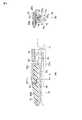
振動子ユニット13について説明すると、操作部本体14の振動子接続部15に着脱可能に連結される振動子ケーシング26が設けられている。この振動子ケーシング26には超音波振動を発生する超音波振動子が内蔵されている。振動子ケーシング26の先端部にはユニット連結部27が設けられ、このユニット連結部27にはリング部材の一部を切り離してC字状に形成した係合リング28が装着されている。ユニット連結部27には超音波振動伝達部材としてのプローブ29が着脱可能に設けられている。プローブ29の基端部にはユニット連結部27にねじ込まれる取付けねじ部30が設けられ、先端部には超音波振動部を構成するプローブ先端部31が設けられている。そして、振動子ユニット13のプローブ29を前記挿入シース21に挿入したとき、プローブ先端部31が保持部材22aから前方に突出し、処置部23を構成するようになっている。なお、32は振動子ケーシング26に接続された超音波用電気ケーブルである。
図2〜図4を参照して操作部11の内部構造について説明する。図2及び図3は超音波処置具の操作部の縦断側面図、図4は図2のA−A線に沿う断面図である。操作部本体14のケーシング14aは合成樹脂材料等の絶縁部材によって形成され、第2電極ピン20が取付けられる電極取付け部33が設けられている。第2電極ピン20は、中間部が絶縁カバー34で被覆され、先端部はプラグ(図示しない)が接続される接続部20aに、基端部はケーシング14aの内部の接続部材35に電気的に接続する接点部20bに形成されている。The
The internal structure of the
操作部本体14の基端部の内周面には雌ねじ部36が設けられ、この雌ねじ部36には接続部材35と固定リング37が螺合固定されている。接続部材35の内部にはこれと同心的に導電筒38が設けられている。この導電筒38の先端部には導電性部材で弾性を有するシリコンゴムでリング状に形成したプローブ保持部材39が設けられている。このプローブ保持部材39は、前記振動子ユニット13のプローブ29が操作部本体14に挿入されたとき、プローブ29と密着して第2電極ピン20とプローブ29とが電気的に導通されるようになっている。 An
導電筒38の外周には操作部本体14の前後方向に絶縁部材で形成された円筒状のスライダ取付け部材40が設けられている。スライダ取付け部材40の先端部には連結筒41が連結ピン42によって着脱可能に連結され、この連結筒41のさらに先端部にはプローブ29が挿通される主チャンネル管42aが接続されている。主チャンネル管42aは管状部材22に内挿されており、この管状部材22の基端部には円筒状の導電部材43が設けられている。この導電部材43にはプローブ保持部材39の外側を覆う円筒状の導電延長部44と導電ゴム170を介して導通可能に接続されている。 A cylindrical
さらに、操作部本体14のケーシング14aに突設された第1電極ピン19のピン本体19aはその中間部が絶縁カバー45で被覆され、先端部はプラグ(図示しない)が接続される接続部19bに、基端部はケーシング14aの内部の突出する接続ピン46が設けられている。接続ピン46には板ばねを略C字状に湾曲した接点板47の中間部が固定され、この接点板47の両端部には導電延長部44を両外側面に弾性的に接触する接点47aが設けられている。そして、第1電極ピン19は、接点板47を介して導電部材43の導電延長部44に電気的に導通し、導電部材43から管状部材22に電気的に導通するようになっている。
また、操作部本体14の内部に設けられたプローブ保持部材39にはスライダ48が前後方向にスライド自在に設けられ、このスライダ48は制限ばね49によって操作部本体14に後方に付勢されている。このスライダ48は操作部本体14に枢支軸17を支点として回動可能な可動ハンドル18と連結ピン50を介して連結され、可動ハンドル18によってスライダ48を介してスライダ取付け部材40が進退し、この進退運動は連結筒41を介して挿入シース21に内挿された駆動ロッド51に伝達されるようになっている。すなわち、可動ハンドル18の矢印a方向の回動によって駆動ロッド51が挿入シース21の内部を前進するようになっている。
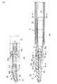
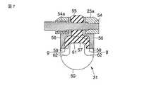
次に、図5〜図7を参照して処置部23の構成を説明する。図5は処置部を示し、(a)は平面図、(b)は縦断側面図、図6は処置部を示し、(a)は図5のB−B線に沿う断面図、(b)はC−C線に沿う断面図、(c)はD−D線に沿う断面図、図7は処置部の横断面図である。Further, the pin
A
Next, the configuration of the
管状部材22の先端部に設けられた保持部材22aに枢支ピン24によって回動可能に設けられた第1の把持部材25は、生体組織を把持しやすいように平面視で、挿入シース21の軸心より左側に僅かに湾曲して設けられている。この第1の把持部材25は、基端側の把持部本体25aと先端側の超音波処置部材25bとからなり、把持部本体25aが枢支ピン24によって保持部材22aに枢支されている。そして、把持部本体25aの基端部には連結ピン53が設けられ、この連結ピン53に駆動ロッド51の先端部が連結されている。 A first grasping
把持部本体25aの先端部は二股状に形成され、その切欠部51aにはねじ部54aを有する枢支ピン54がねじ込み固定され、この枢支ピン54に超音波処置部材25bが上下方向に回動自在に枢支されている。したがって、超音波処置部材25bは第1の把持部材25と同方向に回動可能である。この超音波処置部材25bは、押圧部を形成するパッド部材55と、このパッド部材55の両側に左右対称に設けたサンドイッチ形状の第1電極部56とから構成されている。パッド部材55は、例えばPTFE(登録商標)等の低摩擦材料で形成され、生体組織の把持面側には凹溝57が形成されている。第1電極部56の生体組織の把持面側には生体組織と滑ることなく把持できるように略鋸歯状の歯部58が形成され、歯部58はパッド部材55より把持面側に突出している。
このように構成された第1の把持部材25には、前記振動子ユニット13のプローブ29を挿入シース21に挿入したとき、プローブ先端部31が保持部材22aから前方に突出して対向する。そして、このプローブ先端部31は第1の把持部材25とで生体組織を把持する第2の把持部材59を構成している。すなわち、第2の把持部材59は、丸棒状のプローブ先端部31を鍛造、切削等の加工によって非円形に形成され、第1の把持部材25の凹溝57に対向する把持面61と左右の第1電極部56(歯部58)に対向する第2電極部62が設けられている。The distal end portion of the grip portion
When the
第2の把持部材59の第2電極部62は、第1の把持部材25と遠ざかる方向にあり、把持面61と段差を有している。しかも、把持面61が第1の把持部材25の凹溝57に接触したとき、第2電極部62は第1電極部56(歯部58)に対して隙間gが形成される位置関係にあり、第1電極部56と第2電極部62との短絡を防止していることが特徴である。
したがって、第1の把持部材25を第2の把持部材59に対して接近する方向に回動(把持操作)したとき、まず第1の把持部材25の凹溝57に対して第2の把持部材59の把持面61が接触し、続いて第1電極部52と第2電極部56とが接近するようになっている。The
Accordingly, when the first gripping
また、前記駆動ロッド51の操作によって第1の把持部材25が枢支ピン24を支点として回動し、生体組織を把持する方向に回動して第2の把持部材59とで生体組織を把持する位置関係にあるとき、第1の把持部材25の凹溝57は把持面61と面接触して切開接合面となる。また、左右の歯部58は第2電極部62と略平行の面で対向する凝固接合面となる。つまり、第1と第2の把持部材25,59の開閉方向と直交する方向に切開接合面と凝固接合面があり、生体組織に対して強い把持力が得られることが特徴である。
さらに、第1と第2の把持部材25,59の開閉方向と直交する方向に切開接合面と凝固接合面を設けることにより、プローブ先端部31によって構成される第2の把持部材59が第1の把持部材25より左右方向の両側に張り出さない細径な構造となり、体腔内の狭い腔部に挿入して処置できるように構成されていることも特徴である。
次に、前述のように構成された超音波処置具10の作用について説明する。
例えば、血管封止を目的とした処置を行うために、腹腔に穿刺したトラカール(図示しない)を介して超音波処置具10の挿入部12を腹腔内に挿入する。操作部11の固定ハンドル16と可動ハンドル18とに手指を掛け、固定ハンドル16に対して可動ハンドル18を矢印a方向に回動すると、駆動ロッド51を前進させることができる。駆動ロッド51が前進すると、枢支ピン24を支点として第1の把持部材25が回動し、第2の把持部材59に対して第1の把持部材25を接近させることができる。
したがって、生体組織の目的の部位に挿入部12の処置部23をアプローチし、第2の把持部材59に対して第1の把持部材25を閉じると、図8に示すように、生体組織Sは第1と第2の把持部材25,59間に把持される。つまり、生体組織Sは第1の把持部材25の凹溝57と把持面61との間の切開接合面に把持されるとともに、その把持部分の両側は第1電極部56と第2電極部62との間の凝固接合面で把持される。このとき、第1と第2の把持部材25,59の把持方向と切開接合面及び凝固接合面が同一方向となるため生体組織Sに対する強い把持力が得られ、しかも第1電極部56には歯部58が設けられているため生体組織Sが滑って逃げることも無く確実に把持できる。
この状態で、振動子ユニット13の超音波振動子を駆動すると、超音波振動がプローブ29を介してプローブ先端部31に伝達され、第2の把持部材59が超音波振動する。この超音波振動は、第1と第2の把持部材25,59とで把持された生体組織Sに伝達され、接触部位に摩擦熱が発生して凝固が開始されるとともに、凝固切開が開始される。Further, by operating the
Furthermore, by providing an incision joining surface and a coagulation joining surface in a direction orthogonal to the opening and closing direction of the first and second grasping
Next, the operation of the
For example, in order to perform a treatment aimed at blood vessel sealing, the
Therefore, when the
When the ultrasonic transducer of the
さらに、高周波電源から操作部11の第1電極ピン19に高周波電流を流すと、第1電極ピン19→接点板47→導電延長部44→導電部材43→管状部材22→第1の把持部材25→第1電極部56に流れる。さらに、高周波電流は、第1電極部56から生体組織Sを介して第2電極部62に流れ、第2電極部62→プローブ先端部31→プローブ29→プローブ保持部材39→導電筒38→接続部材35→第2電極ピン20の順に流れて高周波電源装置に帰還される。
したがって、生体組織Sに高周波電流が流れて凝固が進み、生体組織Sが徐々に薄くなり、生体組織Sは第1の把持部材25の凹溝57と把持面61との間で切開されるとともに、第1電極部56と第2電極部62との間で凝固される。生体組織Sが血管の場合、切開部位の近傍が第1電極部56と第2電極部62との間で凝固されて止血状態となっているため、血管封止を目的とした処置が完了する。
さらに、第1の把持部材25が枢支ピン24を支点として回動し、生体組織Sを第2の把持部材59とで把持したとき、第1の把持部材25の凹溝57と把持面61とが面接触し、また、左右の歯部58は第2電極部62と略平行の面で対向する凝固接合面となるため、生体組織Sに対する十分な把持力が得られる。したがって、超音波振動と高周波電流との併用による凝固能力を上げることができ、処置時間も短縮できる。
なお、超音波と高周波を併用するタイミングは同時でも良いし、切開を優位にする場合は超音波を先行させても良いし、凝固を優位にする場合は高周波を先行させても良い。
図9は第2の実施形態を示し、第1の実施形態と同一構成部分は同一番号を付して説明を省略する。図9(a)は処置部の縦断側面図、(b)はE−E線に沿う断面図である。本実施形態は、第1の把持部材71におけるパッド部材72の両側に、第1の把持部材71の回動方向の軸線CLに対して角度(例えば、45°)を持った傾斜面73aを有する第1電極部73を設けたものである。この第1電極部73の生体組織の把持面側には生体組織と滑ることなく把持できるように略鋸歯状の歯部74が形成されている。
さらに、第1の把持部材71とで生体組織を把持する第2の把持部材75は、丸棒状のプローブ先端部31を鍛造、切削等の加工によって非円形(略八角形)に形成され、第1の把持部材71に対向する把持面76と左右の第1電極部73(歯部74)に対向する傾斜面77aを有する第2電極部77が設けられている。第2電極部77は把持面76より第1と第2の把持部材71、75との把持方向から退避して連続しない面に設けられ、しかも、把持面76が第1の把持部材71のパッド部材72に接触したとき、第2電極部77は第1電極部73(歯部74)に対して隙間gが形成される位置関係にある。
そして、第1の把持部材71を生体組織を把持する方向に回動して第2の把持部材75とで生体組織を把持する位置関係にあるとき、第1の把持部材71のパッド部材72は把持面76と面接触して切開接合面となる。また、左右の歯部74は第2電極部77と略平行の面で対向する凝固接合面となる。つまり、第1と第2の把持部材71,75の開閉方向(軸線CL)と直交する方向に切開接合面があり、凝固接合面は略45°の傾斜しており、生体組織に強い把持力が得られるようになっている。さらに、プローブ先端部31によって構成される第2の把持部材75が第1の把持部材71より左右方向の両側に張り出さない細径な構造であり、体腔内の狭い腔部に挿入して処置できるように構成されている。Further, when a high frequency current is passed from the high frequency power source to the
Accordingly, the high-frequency current flows through the living tissue S and the coagulation progresses, and the living tissue S gradually becomes thin. The living tissue S is incised between the
Further, when the first gripping
In addition, the timing which uses an ultrasonic wave and a high frequency simultaneously may be simultaneous, an ultrasonic wave may be preceded when making incision dominant, and a high frequency may be preceded when making coagulation dominant.
FIG. 9 shows a second embodiment, and the same components as those in the first embodiment are denoted by the same reference numerals and description thereof is omitted. FIG. 9A is a longitudinal side view of the treatment portion, and FIG. 9B is a cross-sectional view taken along the line EE. In the present embodiment,
Further, the second grasping
When the first gripping
図10は第3の実施形態を示し、第1の実施形態と同一構成部分は同一番号を付して説明を省略する。図10(a)は処置部の縦断側面図、(b)はF−F線に沿う断面図である。本実施形態は、第1の把持部材81におけるパッド部材82の両側に、第1の把持部材81の回動方向の軸線CLに沿って平行に突出する板状の第1電極部83を設けたものである。この第1電極部83の生体組織の把持面側には生体組織と滑ることなく把持できるように略鋸歯状の歯部84が形成されている。さらに、第1の把持部材81とで生体組織を把持する第2の把持部材85は、丸棒状のプローブ先端部31を鍛造、切削等の加工によって断面矩形状に形成され、第1の把持部材81に対向する把持面86を有する第2電極部87が設けられている。第2電極部87は把持面86より第1と第2の把持部材81、85との把持方向から退避して連続しない面に設けられ、しかも、把持面86が第1の把持部材81のパッド部材82に接触したとき、第2電極部87は第1電極部83(歯部84)に対して隙間gが形成される位置関係にある。
そして、第1の把持部材81を生体組織を把持する方向に回動して第2の把持部材85とで生体組織を把持する位置関係にあるとき、第1の把持部材81のパッド部材82は把持面86と面接触して切開接合面となる。また、左右の第1電極部83は第2電極部87と略平行の面で対向する凝固接合面となる。つまり、第1と第2の把持部材81,85の開閉方向(軸線CL)と直交する方向に切開接合面があり、凝固接合面は略平行面にあり、生体組織に強い把持力が得られる。さらに、プローブ先端部31によって構成される第2の把持部材85が第1の把持部材81より左右方向の両側に張り出さない構造であり、体腔内の狭い腔部に挿入して処置できるように構成されている。FIG. 10 shows a third embodiment, and the same components as those in the first embodiment are denoted by the same reference numerals and description thereof is omitted. FIG. 10A is a longitudinal side view of the treatment portion, and FIG. 10B is a cross-sectional view taken along the line FF. In the present embodiment, plate-like
When the first gripping
図11は第4の実施形態を示し、第1の実施形態と同一構成部分は同一番号を付して説明を省略する。図11(a)は処置部の縦断側面図、(b)はG−G線に沿う断面図である。本実施形態は、第2の把持部材88のみが第1の実施形態と異なるもので、第1の把持部材25とで生体組織を把持する第2の把持部材88は、丸棒状のプローブ先端部31を鍛造、切削等の加工によって断面非円形に形成され、第1の把持部材25のパッド部材55の凹溝57に対向する断面が略山形状に突出する把持面89が設けられている。さらに、把持面89の左右には第1電極部56(歯部58)に対向する平坦面を有する第2電極部90が設けられている。第2電極部90は把持部材当接部25cが保持部材当接部22cと接触したとき、第1電極部56(歯部58)に対して隙間gが形成される位置関係にある。
そして、第1の把持部材25を生体組織を把持する方向に回動して第2の把持部材88とで生体組織を把持する位置関係にあるとき、第1の把持部材25のパッド部材55は把持面89と隙間hが形成される。また、把持面89の左右の第1電極部56は第2電極部90と略平行の面で対向する凝固接合面となる。つまり、第1と第2の把持部材25,88の開閉方向と直交する方向に切開接合面があり、凝固接合面は略平行面にあり、生体組織に強い把持力が得られるようになっている。さらに、プローブ先端部31によって構成される第2の把持部材88が第1の把持部材25より左右方向の両側に張り出さない構造であり、体腔内の狭い腔部に挿入して処置できるように構成されている。FIG. 11 shows a fourth embodiment, and the same components as those in the first embodiment are denoted by the same reference numerals and description thereof is omitted. Fig.11 (a) is a vertical side view of a treatment part, (b) is sectional drawing which follows a GG line. In this embodiment, only the second gripping
When the first gripping
本実施形態では、パッド部材55と把持面89は接触しないため、生体組織を切開する際は、生体組織と把持面89が強く接触する方向にテンションを与える必要があるが、パッド部材55が磨耗することが無くなるため、耐性が向上する。
図12は第5の実施形態を示し、第1の実施形態と同一構成部分は同一番号を付して説明を省略する。図12(a)は処置部の斜視図、(b)は処置状態の横断面図である。本実施形態は、第1の把持部材91は平板状に形成され、この把持面側には凸円弧状のパッド部材92が設けられている。第1の把持部材91におけるパッド部材92の両側には第1電極部93が設けられている。第1の把持部材91とで生体組織Sを把持する第2の把持部材94は、丸棒状のプローブ先端部31を鍛造、切削等の加工によって非円形に形成され、第1の把持部材91に対向する把持面95はパッド部材92と嵌合するように凹円弧状に形成され、把持面95の左右には第1電極部93に対向する稜線からなる第2電極部96が設けられている。In this embodiment, since the
FIG. 12 shows a fifth embodiment, and the same components as those in the first embodiment are denoted by the same reference numerals and description thereof is omitted. FIG. 12A is a perspective view of the treatment portion, and FIG. 12B is a cross-sectional view of the treatment state. In the present embodiment, the
そして、第1の把持部材91を生体組織Sを把持する方向に回動して第2の把持部材94とで生体組織Sを把持する位置関係にあるとき、第1の把持部材91のパッド部材92は把持面95と面接触して切開接合面となる。また、左右の第1電極部93は第2電極部96と略平行の面で対向する凝固接合面となり、生体組織Sに強い把持力が得られるようになっている。本実施形態によると、プローブ先端部31を第1の把持部材91よりも小型にすることができ、全体として細径化が可能となる。
図13は第6の実施形態を示し、第1の実施形態と同一構成部分は同一番号を付して説明を省略する。図13は処置部の斜視図である。本実施形態は、第1の把持部材101は断面が略半円状で、把持面側には凹溝102が形成され、この凹溝102にはパッド部材103が埋設されている。第1の把持部材101におけるパッド部材103の両側には第1電極部104が設けられている。第1の把持部材101とで生体組織を把持する第2の把持部材105は、丸棒状のプローブ先端部31を鍛造、切削等の加工によって非円形に形成され、第1の把持部材101に対向する把持面106はパッド部材103と接触する例えば波形の凹凸部に形成され、この把持面106の左右には第1電極部104に対向する平坦面からなる第2電極部107が設けられている。Then, when the first gripping
FIG. 13 shows a sixth embodiment, and the same components as those of the first embodiment are denoted by the same reference numerals and description thereof is omitted. FIG. 13 is a perspective view of the treatment portion. In this embodiment, the first holding
そして、第1の把持部材101を生体組織を把持する方向に回動して第2の把持部材105とで生体組織を把持する位置関係にあるとき、第1の把持部材101のパッド部材103は把持面106と部分的に接触して切開接合面となる。また、左右の第1電極部104は第2電極部107と略平行の面で対向する凝固接合面となり、生体組織に強い把持力が得られるようになっている。本実施形態によると、第1電極部104に滑り止めの歯を設ける必要が無くなるため、より安定した凝固が可能となる。
図14は第7の実施形態を示し、第1の実施形態と同一構成部分は同一番号を付して説明を省略する。図14(a)は処置部の斜視図、(b)はH−H線に沿う断面図である。本実施形態は、第1の把持部材111は断面が円柱状で、把持面側には逆三角形状の凹溝112が形成され、この凹溝112にはパッド部材113が埋設されている。第1の把持部材111におけるパッド部材113の両側にはV字状に突出する第1電極部114が設けられている。第1の把持部材111とで生体組織を把持する第2の把持部材115は、丸棒状のプローブ先端部31を鍛造、切削等の加工によって非円形に形成され、第1の把持部材111に対向する把持面116はパッド部材113と接触する三角形状の凸部に形成され、この把持面116の左右には第1電極部114に対向するV字状の凹部からなる第2電極部117が設けられている。When the first gripping
FIG. 14 shows a seventh embodiment, and the same components as those of the first embodiment are denoted by the same reference numerals and description thereof is omitted. 14A is a perspective view of the treatment portion, and FIG. 14B is a cross-sectional view taken along the line HH. In the present embodiment, the first holding
そして、第1の把持部材111を生体組織を把持する方向に回動して第2の把持部材115とで生体組織を把持する位置関係にあるとき、第1の把持部材111のパッド部材113は把持面116と線接触して切開接合面となる。また、左右の第1電極部114は第2電極部117と複数面で接触する凝固エリアが広い凝固接合面となる。 When the first gripping
図15は第8の実施形態を示し、第1の実施形態と同一構成部分は同一番号を付して説明を省略する。図15は処置部の横断面図である。本実施形態は、第1の把持部材121はパッド部材122を挟む一対の部材によって形成され、パッド部材122とともに断面が凹円弧状で、把持面側には凹円弧状の凹溝123が形成されている。第1の把持部材121におけるパッド部材122の両側には平坦面からなる第1電極部124と第2電極部127が設けられている。第1の把持部材121とで生体組織を把持する第2の把持部材125は、丸棒状のプローブ先端部31によって形成され、第1の把持部材121に対向する把持面126はパッド部材122と接触する凸円弧状に形成されている。 FIG. 15 shows an eighth embodiment, and the same components as those of the first embodiment are denoted by the same reference numerals and description thereof is omitted. FIG. 15 is a cross-sectional view of the treatment portion. In the present embodiment, the
そして、第1の把持部材121を生体組織を把持する方向に回動して第2の把持部材125とで生体組織を把持する位置関係にあるとき、第1の把持部材121のパッド部材122は把持面126と面接触して切開接合面となる。また、把持面126の左右の第1電極部124及び第2電極部127は凝固面となり、生体組織の圧縮された部分に高周波が通電するようになっている。 When the first gripping
図16は第9の実施形態を示し、第1の実施形態と同一構成部分は同一番号を付して説明を省略する。図16は処置部の斜視図である。本実施形態は、第1の把持部材131は2分割され、これら第1の把持部材131は基端部が保持部材22aの山形面に対して枢支軸132を支点として回動自在に枢支されている。第1の把持部材131の片側にはパッド部材133が設けられ、第1の把持部材131とともに丸棒状のプローブ先端部31の軸心31aに向って回動するようになっている。そして、第1の把持部材131のプローブ先端部31に対面する側には第1電極部134が設けられている。なお、第1の把持部材131は付勢ばね等によって開方向に付勢され、管状部材22の軸方向に前進するシース部材等によって内側に押付けられて閉方向に回動するようにしてもよい。
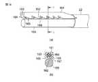
さらに、第1の把持部材131とで生体組織を把持する第2の把持部材135は、丸棒状のプローブ先端部31を鍛造、切削等の加工によって非円形に形成され、第1の把持部材131のパッド部材133に対向する把持面136は稜線によって形成され、把持面136の左右には傾斜面137aを有する第2電極部137が設けられている。FIG. 16 shows a ninth embodiment, and the same components as those of the first embodiment are denoted by the same reference numerals and description thereof is omitted. FIG. 16 is a perspective view of the treatment section. In the present embodiment, the first gripping
Further, the second grasping
そして、第1の把持部材131を生体組織を把持する方向に回動して第2の把持部材135とで生体組織を把持する位置関係にあるとき、第1の把持部材131のパッド部材133は把持面136と接触して切開接合面となる。また、左右の第1電極部134は第2電極部137と略平行の面で対向する凝固接合面となる。つまり、第1と第2の把持部材131,135の開閉方向はプローブ先端部31の半径方向となり、この開閉方向と直交する方向に凝固接合面があり、生体組織に強い把持力が得られるようになっている。 When the first grasping
図17は第10の実施形態を示し、第1の実施形態と同一構成部分は同一番号を付して説明を省略する。図17は処置部の横断面図である。本実施形態は、第2の把持部材138のみが第1の実施形態と異なるもので、第1の把持部材25とで生体組織を把持する第2の把持部材138は、丸棒状のプローブ先端部31を鍛造、切削等の加工によって断面非円形に形成され、第1の把持部材25のパッド部材55の凹溝57に対向する凸状部からなる把持面139と左右の第1電極部56(歯部58)に対向する平坦面を有する第2電極部140が設けられている。第2電極部140は把持面139が第1の把持部材25のパッド部材55に接触したとき、第1電極部56(歯部58)に対して隙間gが形成される位置関係にある。さらに、第2の把持部材138の凸状部からなる把持面139は絶縁コーティングによって絶縁層141が形成され、第2電極部140は絶縁コーティングされていない構造である。したがって、第1電極部56と第2電極部140の面積を略同じにして電流密度を高くし、効率的の凝固できるようにしている。
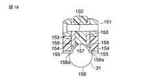
図18は第11の実施形態を示し、第1の実施形態と同一構成部分は同一番号を付して説明を省略する。図18は処置部の横断面図である。本実施形態の第1の把持部材151は、パッド部材152を挟んで左右に第1電極部153を設けたサンドイッチ構造の外側には合成樹脂材料からなる絶縁ブロック154が一体的に設けられている。絶縁ブロック154は第1電極部153より把持方向に突出しており、この絶縁ブロック154の突出部には歯部155が形成されている。FIG. 17 shows the tenth embodiment, and the same components as those of the first embodiment are denoted by the same reference numerals and description thereof is omitted. FIG. 17 is a cross-sectional view of the treatment portion. In this embodiment, only the second gripping
FIG. 18 shows an eleventh embodiment, and the same components as those of the first embodiment are denoted by the same reference numerals and description thereof is omitted. FIG. 18 is a cross-sectional view of the treatment portion. In the first gripping
第1の把持部材151とで生体組織を把持する第2の把持部材156は、丸棒状のプローブ先端部31を鍛造、切削等の加工によって非円形に形成され、第1の把持部材151に対向する把持面157はパッド部材152と接触する凸部に形成され、この把持面157の左右には第1電極部153に対向する傾斜面158aを有する第2電極部158が設けられている。 The second
そして、第1の把持部材151を生体組織を把持する方向に回動して第2の把持部材156とで生体組織を把持する位置関係にあるとき、第1の把持部材151のパッド部材152は把持面157と接触して切開接合面となる。また、把持面157の左右の第1電極部153は第2電極部158と対向して凝固接合面となるように構成されている。本実施形態によると、プローブ先端部31に横方向の力等が加わった場合でも、第1電極153と接触することは無いので、プローブ先端部31の耐性向上に繋がる。
図19は開示例を示し、第1の実施形態と同一構成部分は同一番号を付して説明を省略する。図19(a)は処置部の縦断側面図、(b)はI−I線に沿う断面図である。第1の把持部材161は断面が矩形状の部材であり、その把持面側には鋸歯状の歯部162が形成されている。第1の把持部材161には軸方向に凹溝163が設けられ、この凹溝163には第1電極部164が埋設されている。第1の把持部材161における第1電極部164の両側にはパッド部部材165が設けられている。第1の把持部材161とで生体組織を把持する第2の把持部材166は、丸棒状のプローブ先端部31によって形成され、第1の把持部材161に対向する把持面167はパッド部材165と接触するようになっている。把持面167の左右には第1電極部164に対向する円弧面からなる第2電極部168が設けられている。When the first gripping
FIG. 19 shows an example of disclosure, and the same components as those in the first embodiment are given the same reference numerals and explanations thereof are omitted. FIG. 19A is a longitudinal side view of the treatment section, and FIG. 19B is a cross-sectional view taken along the line II. The first
そして、第1の把持部材161を生体組織を把持する方向に回動して第2の把持部材166とで生体組織を把持したとき、歯部162が生体組織に接触し、第1の把持部材161のパッド部材164は把持面167と部分的に接触して切開接合面となる。また、左右の第1電極部165は第2電極部168と対向する凝固接合面となるように構成されている。 Then, when the first grasping
なお、この発明は、前記実施形態そのままに限定されるものではなく、実施段階ではその要旨を逸脱しない範囲で構成要素を変形して具体化できる。また、前記実施形態に開示されている複数の構成要素の適宜な組合せにより種々の発明を形成できる。例えば、実施形態に示される全構成要素から幾つかの構成要素を削除してもよい。さらに、異なる実施形態に亘る構成要素を適宜組合わせてもよい。 Note that the present invention is not limited to the above-described embodiment as it is, and can be embodied by modifying the constituent elements without departing from the scope of the invention in the implementation stage. In addition, various inventions can be formed by appropriately combining a plurality of components disclosed in the embodiment. For example, some components may be deleted from all the components shown in the embodiment. Furthermore, you may combine suitably the component covering different embodiment.
11…操作部、12…挿入シース、13…振動子ユニット、23…処置部、25…第1の把持部材、55…パッド部材(押圧部)、56…第1電極部、59…第2の把持部材、62…第2電極部 DESCRIPTION OF
Claims (5)
Translated fromJapanese前記第1の把持部材に対して開閉可能に設けられ、該第1の把持部材との間で生体組織を把持する第2の把持部材と、
前記第1もしくは第2の把持部材の一方に設けられ、超音波振動子と接続されて超音波振動する超音波振動部と、
前記第1もしくは第2の把持部材の他方に設けられ、前記超音波振動部と対向し、該超音波振動部との間で生体組織を押圧する押圧部と、
前記超音波振動部と前記押圧部との間に設けられた切開面を有した超音波凝固切開手段と、
前記第1の把持部材に設けられた第1電極部と、
前記第2の把持部材に設けられた第2電極部と、
前記第1電極部と前記第2電極部との間に設けられかつ前記切開面以外の位置に設けられた凝固面を有し、該第1電極部と前記第2電極部とを対向して設けて生体組織を凝固する高周波凝固手段と、
を具備したことを特徴とする外科用処置具。A first gripping member;
A second gripping member provided so as to be openable and closable with respect to the first gripping member, and gripping a living tissue with the first gripping member;
An ultrasonic vibration part that is provided on one of the first or second gripping member and is connected to an ultrasonic vibrator to vibrate ultrasonically;
A pressing portionthat is provided on the other of the first or second gripping member, faces the ultrasonic vibration portion, and presses the living tissue with the ultrasonic vibration portion;
Ultrasonic coagulation and incision meanshaving an incision surface provided between the ultrasonic vibration part and the pressing part ;
A first electrode portion provided on the first holding member;
A second electrode portion provided on the second gripping member;
A coagulation surface provided between the first electrode portion and the second electrode portion and provided at a position other than the incision surface , wherein the first electrode portion and the second electrode portion are opposed to each other; A high-frequency coagulation means for coagulating the living tissue;
A surgical treatment instrument comprising:
前記第1の把持部材に対して開閉可能に設けられ、該第1の把持部材との間で生体組織を把持する第2の把持部材と、
前記第1もしくは第2の把持部材の一方に設けられ、超音波振動子と接続されて超音波振動する超音波振動部と、
前記第1もしくは第2の把持部材の他方に設けられ、前記超音波振動部と対向し、該超音波振動部との間で生体組織を押圧する押圧部と、
前記超音波振動部と前記押圧部との間に設けられた切開面を有した超音波凝固切開手段と、
前記第1の把持部材に設けられた第1電極部と、
前記第2の把持部材に設けられた第2電極部と、
前記第1電極部と前記第1電極部との間に設けられた凝固面を有し、第1電極部と第2電極部とを対向して設けて生体組織を凝固するとともに、前記第1と第2の把持部材との把持操作によって前記超音波凝固切開手段を構成する押圧部と前記超音波振動部とが接したとき、前記第1電極部と前記第2電極部の間に隙間を形成する位置関係にある高周波凝固手段と、
を具備したことを特徴とする外科用処置具。A first gripping member;
A second gripping member provided so as to be openable and closable with respect to the first gripping member, and gripping a living tissue with the first gripping member;
An ultrasonic vibration part that is provided on one of the first or second gripping member and is connected to an ultrasonic vibrator to vibrate ultrasonically;
A pressing portionthat is provided on the other of the first or second gripping member, faces the ultrasonic vibration portion, and presses the living tissue with the ultrasonic vibration portion;
Ultrasonic coagulation and incision meanshaving an incision surface provided between the ultrasonic vibration part and the pressing part ;
A first electrode portion provided on the first holding member;
A second electrode portion provided on the second gripping member;
The coagulation surface is provided between the first electrode part and the first electrode part, and the first electrode part and the second electrode partare provided to face each other to coagulate a living tissue, and the first electrode part When the pressing portion constituting the ultrasonic coagulation / cutting means and the ultrasonic vibration portion come into contact with each other by a gripping operation between the first electrode portion and the second gripping member, a gap is formed between the first electrode portion and the second electrode portion. High-frequency coagulation means in a positional relationship to be formed;
A surgical treatment instrument comprising:
Priority Applications (5)
| Application Number | Priority Date | Filing Date | Title |
|---|---|---|---|
| JP2006184663AJP4157574B2 (en) | 2006-07-04 | 2006-07-04 | Surgical instrument |
| US11/459,411US7905881B2 (en) | 2006-07-04 | 2006-07-24 | Surgical instrument |
| EP07012598.4AEP1875875B1 (en) | 2006-07-04 | 2007-06-27 | Surgical instrument |
| KR1020070066361AKR101353757B1 (en) | 2006-07-04 | 2007-07-03 | Surgical Instrument |
| CNA2007101229696ACN101099691A (en) | 2006-07-04 | 2007-07-04 | Surgical Disposal Instruments |
Applications Claiming Priority (1)
| Application Number | Priority Date | Filing Date | Title |
|---|---|---|---|
| JP2006184663AJP4157574B2 (en) | 2006-07-04 | 2006-07-04 | Surgical instrument |
Publications (2)
| Publication Number | Publication Date |
|---|---|
| JP2008011987A JP2008011987A (en) | 2008-01-24 |
| JP4157574B2true JP4157574B2 (en) | 2008-10-01 |
Family
ID=38611071
Family Applications (1)
| Application Number | Title | Priority Date | Filing Date |
|---|---|---|---|
| JP2006184663AActiveJP4157574B2 (en) | 2006-07-04 | 2006-07-04 | Surgical instrument |
Country Status (5)
| Country | Link |
|---|---|
| US (1) | US7905881B2 (en) |
| EP (1) | EP1875875B1 (en) |
| JP (1) | JP4157574B2 (en) |
| KR (1) | KR101353757B1 (en) |
| CN (1) | CN101099691A (en) |
Families Citing this family (642)
| Publication number | Priority date | Publication date | Assignee | Title |
|---|---|---|---|---|
| US7364577B2 (en) | 2002-02-11 | 2008-04-29 | Sherwood Services Ag | Vessel sealing system |
| ES2262639T3 (en) | 2001-04-06 | 2006-12-01 | Sherwood Services Ag | SHUTTER AND DIVIDER OF GLASSES WITH BUMPER MEMBERS N OCONDUCTIVES. |
| US11229472B2 (en) | 2001-06-12 | 2022-01-25 | Cilag Gmbh International | Modular battery powered handheld surgical instrument with multiple magnetic position sensors |
| US7931649B2 (en) | 2002-10-04 | 2011-04-26 | Tyco Healthcare Group Lp | Vessel sealing instrument with electrical cutting mechanism |
| US9060770B2 (en) | 2003-05-20 | 2015-06-23 | Ethicon Endo-Surgery, Inc. | Robotically-driven surgical instrument with E-beam driver |
| US20070084897A1 (en) | 2003-05-20 | 2007-04-19 | Shelton Frederick E Iv | Articulating surgical stapling instrument incorporating a two-piece e-beam firing mechanism |
| US7367976B2 (en) | 2003-11-17 | 2008-05-06 | Sherwood Services Ag | Bipolar forceps having monopolar extension |
| US8182501B2 (en) | 2004-02-27 | 2012-05-22 | Ethicon Endo-Surgery, Inc. | Ultrasonic surgical shears and method for sealing a blood vessel using same |
| US9072535B2 (en) | 2011-05-27 | 2015-07-07 | Ethicon Endo-Surgery, Inc. | Surgical stapling instruments with rotatable staple deployment arrangements |
| US8215531B2 (en) | 2004-07-28 | 2012-07-10 | Ethicon Endo-Surgery, Inc. | Surgical stapling instrument having a medical substance dispenser |
| US11890012B2 (en) | 2004-07-28 | 2024-02-06 | Cilag Gmbh International | Staple cartridge comprising cartridge body and attached support |
| US11998198B2 (en) | 2004-07-28 | 2024-06-04 | Cilag Gmbh International | Surgical stapling instrument incorporating a two-piece E-beam firing mechanism |
| US20060079879A1 (en) | 2004-10-08 | 2006-04-13 | Faller Craig N | Actuation mechanism for use with an ultrasonic surgical instrument |
| US7909823B2 (en) | 2005-01-14 | 2011-03-22 | Covidien Ag | Open vessel sealing instrument |
| US11246590B2 (en) | 2005-08-31 | 2022-02-15 | Cilag Gmbh International | Staple cartridge including staple drivers having different unfired heights |
| US7669746B2 (en) | 2005-08-31 | 2010-03-02 | Ethicon Endo-Surgery, Inc. | Staple cartridges for forming staples having differing formed staple heights |
| US9237891B2 (en) | 2005-08-31 | 2016-01-19 | Ethicon Endo-Surgery, Inc. | Robotically-controlled surgical stapling devices that produce formed staples having different lengths |
| US10159482B2 (en) | 2005-08-31 | 2018-12-25 | Ethicon Llc | Fastener cartridge assembly comprising a fixed anvil and different staple heights |
| US11484312B2 (en) | 2005-08-31 | 2022-11-01 | Cilag Gmbh International | Staple cartridge comprising a staple driver arrangement |
| US7934630B2 (en) | 2005-08-31 | 2011-05-03 | Ethicon Endo-Surgery, Inc. | Staple cartridges for forming staples having differing formed staple heights |
| US20070191713A1 (en) | 2005-10-14 | 2007-08-16 | Eichmann Stephen E | Ultrasonic device for cutting and coagulating |
| US20070106317A1 (en) | 2005-11-09 | 2007-05-10 | Shelton Frederick E Iv | Hydraulically and electrically actuated articulation joints for surgical instruments |
| US7621930B2 (en) | 2006-01-20 | 2009-11-24 | Ethicon Endo-Surgery, Inc. | Ultrasound medical instrument having a medical ultrasonic blade |
| US7753904B2 (en) | 2006-01-31 | 2010-07-13 | Ethicon Endo-Surgery, Inc. | Endoscopic surgical instrument with a handle that can articulate with respect to the shaft |
| US7845537B2 (en) | 2006-01-31 | 2010-12-07 | Ethicon Endo-Surgery, Inc. | Surgical instrument having recording capabilities |
| US11278279B2 (en) | 2006-01-31 | 2022-03-22 | Cilag Gmbh International | Surgical instrument assembly |
| US11793518B2 (en) | 2006-01-31 | 2023-10-24 | Cilag Gmbh International | Powered surgical instruments with firing system lockout arrangements |
| US8820603B2 (en) | 2006-01-31 | 2014-09-02 | Ethicon Endo-Surgery, Inc. | Accessing data stored in a memory of a surgical instrument |
| US20110024477A1 (en) | 2009-02-06 | 2011-02-03 | Hall Steven G | Driven Surgical Stapler Improvements |
| US8708213B2 (en) | 2006-01-31 | 2014-04-29 | Ethicon Endo-Surgery, Inc. | Surgical instrument having a feedback system |
| US20120292367A1 (en) | 2006-01-31 | 2012-11-22 | Ethicon Endo-Surgery, Inc. | Robotically-controlled end effector |
| US8186555B2 (en) | 2006-01-31 | 2012-05-29 | Ethicon Endo-Surgery, Inc. | Motor-driven surgical cutting and fastening instrument with mechanical closure system |
| US11224427B2 (en) | 2006-01-31 | 2022-01-18 | Cilag Gmbh International | Surgical stapling system including a console and retraction assembly |
| US20110295295A1 (en) | 2006-01-31 | 2011-12-01 | Ethicon Endo-Surgery, Inc. | Robotically-controlled surgical instrument having recording capabilities |
| US8992422B2 (en) | 2006-03-23 | 2015-03-31 | Ethicon Endo-Surgery, Inc. | Robotically-controlled endoscopic accessory channel |
| US8322455B2 (en) | 2006-06-27 | 2012-12-04 | Ethicon Endo-Surgery, Inc. | Manually driven surgical cutting and fastening instrument |
| US7506791B2 (en) | 2006-09-29 | 2009-03-24 | Ethicon Endo-Surgery, Inc. | Surgical stapling instrument with mechanical mechanism for limiting maximum tissue compression |
| US10568652B2 (en) | 2006-09-29 | 2020-02-25 | Ethicon Llc | Surgical staples having attached drivers of different heights and stapling instruments for deploying the same |
| US11980366B2 (en) | 2006-10-03 | 2024-05-14 | Cilag Gmbh International | Surgical instrument |
| US8632535B2 (en) | 2007-01-10 | 2014-01-21 | Ethicon Endo-Surgery, Inc. | Interlock and surgical instrument including same |
| US11291441B2 (en) | 2007-01-10 | 2022-04-05 | Cilag Gmbh International | Surgical instrument with wireless communication between control unit and remote sensor |
| US8652120B2 (en) | 2007-01-10 | 2014-02-18 | Ethicon Endo-Surgery, Inc. | Surgical instrument with wireless communication between control unit and sensor transponders |
| US8684253B2 (en) | 2007-01-10 | 2014-04-01 | Ethicon Endo-Surgery, Inc. | Surgical instrument with wireless communication between a control unit of a robotic system and remote sensor |
| US20080169333A1 (en) | 2007-01-11 | 2008-07-17 | Shelton Frederick E | Surgical stapler end effector with tapered distal end |
| US11039836B2 (en) | 2007-01-11 | 2021-06-22 | Cilag Gmbh International | Staple cartridge for use with a surgical stapling instrument |
| US7673782B2 (en) | 2007-03-15 | 2010-03-09 | Ethicon Endo-Surgery, Inc. | Surgical stapling instrument having a releasable buttress material |
| US20080234709A1 (en) | 2007-03-22 | 2008-09-25 | Houser Kevin L | Ultrasonic surgical instrument and cartilage and bone shaping blades therefor |
| US8911460B2 (en) | 2007-03-22 | 2014-12-16 | Ethicon Endo-Surgery, Inc. | Ultrasonic surgical instruments |
| US8057498B2 (en) | 2007-11-30 | 2011-11-15 | Ethicon Endo-Surgery, Inc. | Ultrasonic surgical instrument blades |
| US8226675B2 (en) | 2007-03-22 | 2012-07-24 | Ethicon Endo-Surgery, Inc. | Surgical instruments |
| US8142461B2 (en) | 2007-03-22 | 2012-03-27 | Ethicon Endo-Surgery, Inc. | Surgical instruments |
| US8893946B2 (en) | 2007-03-28 | 2014-11-25 | Ethicon Endo-Surgery, Inc. | Laparoscopic tissue thickness and clamp load measuring devices |
| US11564682B2 (en) | 2007-06-04 | 2023-01-31 | Cilag Gmbh International | Surgical stapler device |
| US8931682B2 (en) | 2007-06-04 | 2015-01-13 | Ethicon Endo-Surgery, Inc. | Robotically-controlled shaft based rotary drive systems for surgical instruments |
| US7753245B2 (en) | 2007-06-22 | 2010-07-13 | Ethicon Endo-Surgery, Inc. | Surgical stapling instruments |
| US11849941B2 (en) | 2007-06-29 | 2023-12-26 | Cilag Gmbh International | Staple cartridge having staple cavities extending at a transverse angle relative to a longitudinal cartridge axis |
| US8882791B2 (en) | 2007-07-27 | 2014-11-11 | Ethicon Endo-Surgery, Inc. | Ultrasonic surgical instruments |
| US8808319B2 (en) | 2007-07-27 | 2014-08-19 | Ethicon Endo-Surgery, Inc. | Surgical instruments |
| US8523889B2 (en) | 2007-07-27 | 2013-09-03 | Ethicon Endo-Surgery, Inc. | Ultrasonic end effectors with increased active length |
| US8348967B2 (en)* | 2007-07-27 | 2013-01-08 | Ethicon Endo-Surgery, Inc. | Ultrasonic surgical instruments |
| US9044261B2 (en) | 2007-07-31 | 2015-06-02 | Ethicon Endo-Surgery, Inc. | Temperature controlled ultrasonic surgical instruments |
| US8252012B2 (en) | 2007-07-31 | 2012-08-28 | Ethicon Endo-Surgery, Inc. | Ultrasonic surgical instrument with modulator |
| US8430898B2 (en) | 2007-07-31 | 2013-04-30 | Ethicon Endo-Surgery, Inc. | Ultrasonic surgical instruments |
| US8512365B2 (en) | 2007-07-31 | 2013-08-20 | Ethicon Endo-Surgery, Inc. | Surgical instruments |
| US20090088785A1 (en)* | 2007-09-28 | 2009-04-02 | Shinya Masuda | Surgical operating apparatus |
| EP2217157A2 (en) | 2007-10-05 | 2010-08-18 | Ethicon Endo-Surgery, Inc. | Ergonomic surgical instruments |
| US10010339B2 (en) | 2007-11-30 | 2018-07-03 | Ethicon Llc | Ultrasonic surgical blades |
| US7819298B2 (en) | 2008-02-14 | 2010-10-26 | Ethicon Endo-Surgery, Inc. | Surgical stapling apparatus with control features operable with one hand |
| JP5410110B2 (en) | 2008-02-14 | 2014-02-05 | エシコン・エンド−サージェリィ・インコーポレイテッド | Surgical cutting / fixing instrument with RF electrode |
| US8636736B2 (en) | 2008-02-14 | 2014-01-28 | Ethicon Endo-Surgery, Inc. | Motorized surgical cutting and fastening instrument |
| US8758391B2 (en) | 2008-02-14 | 2014-06-24 | Ethicon Endo-Surgery, Inc. | Interchangeable tools for surgical instruments |
| US7866527B2 (en) | 2008-02-14 | 2011-01-11 | Ethicon Endo-Surgery, Inc. | Surgical stapling apparatus with interlockable firing system |
| US8573465B2 (en) | 2008-02-14 | 2013-11-05 | Ethicon Endo-Surgery, Inc. | Robotically-controlled surgical end effector system with rotary actuated closure systems |
| US9179912B2 (en) | 2008-02-14 | 2015-11-10 | Ethicon Endo-Surgery, Inc. | Robotically-controlled motorized surgical cutting and fastening instrument |
| US11986183B2 (en) | 2008-02-14 | 2024-05-21 | Cilag Gmbh International | Surgical cutting and fastening instrument comprising a plurality of sensors to measure an electrical parameter |
| US11272927B2 (en) | 2008-02-15 | 2022-03-15 | Cilag Gmbh International | Layer arrangements for surgical staple cartridges |
| US9585657B2 (en) | 2008-02-15 | 2017-03-07 | Ethicon Endo-Surgery, Llc | Actuator for releasing a layer of material from a surgical end effector |
| US20090216157A1 (en)* | 2008-02-22 | 2009-08-27 | Norihiro Yamada | Ultrasonic operating apparatus |
| US8048074B2 (en) | 2008-03-28 | 2011-11-01 | Olympus Medical Systems Corp. | Surgical operating apparatus |
| US9089360B2 (en) | 2008-08-06 | 2015-07-28 | Ethicon Endo-Surgery, Inc. | Devices and techniques for cutting and coagulating tissue |
| US8058771B2 (en) | 2008-08-06 | 2011-11-15 | Ethicon Endo-Surgery, Inc. | Ultrasonic device for cutting and coagulating with stepped output |
| US11648005B2 (en) | 2008-09-23 | 2023-05-16 | Cilag Gmbh International | Robotically-controlled motorized surgical instrument with an end effector |
| US8210411B2 (en) | 2008-09-23 | 2012-07-03 | Ethicon Endo-Surgery, Inc. | Motor-driven surgical cutting instrument |
| US9005230B2 (en) | 2008-09-23 | 2015-04-14 | Ethicon Endo-Surgery, Inc. | Motorized surgical instrument |
| US9386983B2 (en) | 2008-09-23 | 2016-07-12 | Ethicon Endo-Surgery, Llc | Robotically-controlled motorized surgical instrument |
| US8142473B2 (en) | 2008-10-03 | 2012-03-27 | Tyco Healthcare Group Lp | Method of transferring rotational motion in an articulating surgical instrument |
| US8016827B2 (en) | 2008-10-09 | 2011-09-13 | Tyco Healthcare Group Lp | Apparatus, system, and method for performing an electrosurgical procedure |
| US8608045B2 (en) | 2008-10-10 | 2013-12-17 | Ethicon Endo-Sugery, Inc. | Powered surgical cutting and stapling apparatus with manually retractable firing system |
| US8114122B2 (en) | 2009-01-13 | 2012-02-14 | Tyco Healthcare Group Lp | Apparatus, system, and method for performing an electrosurgical procedure |
| US8517239B2 (en) | 2009-02-05 | 2013-08-27 | Ethicon Endo-Surgery, Inc. | Surgical stapling instrument comprising a magnetic element driver |
| US8444036B2 (en) | 2009-02-06 | 2013-05-21 | Ethicon Endo-Surgery, Inc. | Motor driven surgical fastener device with mechanisms for adjusting a tissue gap within the end effector |
| RU2525225C2 (en) | 2009-02-06 | 2014-08-10 | Этикон Эндо-Серджери, Инк. | Improvement of drive surgical suturing instrument |
| US8187273B2 (en) | 2009-05-07 | 2012-05-29 | Tyco Healthcare Group Lp | Apparatus, system, and method for performing an electrosurgical procedure |
| US9700339B2 (en) | 2009-05-20 | 2017-07-11 | Ethicon Endo-Surgery, Inc. | Coupling arrangements and methods for attaching tools to ultrasonic surgical instruments |
| US8650728B2 (en) | 2009-06-24 | 2014-02-18 | Ethicon Endo-Surgery, Inc. | Method of assembling a transducer for a surgical instrument |
| US8246618B2 (en) | 2009-07-08 | 2012-08-21 | Tyco Healthcare Group Lp | Electrosurgical jaws with offset knife |
| CN102497827B (en)* | 2009-07-15 | 2016-06-01 | 伊西康内外科公司 | Electrosurgical generator for ultrasonic surgical instrument |
| US8461744B2 (en) | 2009-07-15 | 2013-06-11 | Ethicon Endo-Surgery, Inc. | Rotating transducer mount for ultrasonic surgical instruments |
| US8663220B2 (en) | 2009-07-15 | 2014-03-04 | Ethicon Endo-Surgery, Inc. | Ultrasonic surgical instruments |
| US9017326B2 (en)* | 2009-07-15 | 2015-04-28 | Ethicon Endo-Surgery, Inc. | Impedance monitoring apparatus, system, and method for ultrasonic surgical instruments |
| US8133254B2 (en) | 2009-09-18 | 2012-03-13 | Tyco Healthcare Group Lp | In vivo attachable and detachable end effector assembly and laparoscopic surgical instrument and methods therefor |
| US8112871B2 (en) | 2009-09-28 | 2012-02-14 | Tyco Healthcare Group Lp | Method for manufacturing electrosurgical seal plates |
| US10172669B2 (en) | 2009-10-09 | 2019-01-08 | Ethicon Llc | Surgical instrument comprising an energy trigger lockout |
| USRE47996E1 (en) | 2009-10-09 | 2020-05-19 | Ethicon Llc | Surgical generator for ultrasonic and electrosurgical devices |
| US10441345B2 (en) | 2009-10-09 | 2019-10-15 | Ethicon Llc | Surgical generator for ultrasonic and electrosurgical devices |
| US11090104B2 (en) | 2009-10-09 | 2021-08-17 | Cilag Gmbh International | Surgical generator for ultrasonic and electrosurgical devices |
| US9168054B2 (en) | 2009-10-09 | 2015-10-27 | Ethicon Endo-Surgery, Inc. | Surgical generator for ultrasonic and electrosurgical devices |
| US9050093B2 (en) | 2009-10-09 | 2015-06-09 | Ethicon Endo-Surgery, Inc. | Surgical generator for ultrasonic and electrosurgical devices |
| US8851354B2 (en) | 2009-12-24 | 2014-10-07 | Ethicon Endo-Surgery, Inc. | Surgical cutting instrument that analyzes tissue thickness |
| US8220688B2 (en) | 2009-12-24 | 2012-07-17 | Ethicon Endo-Surgery, Inc. | Motor-driven surgical cutting instrument with electric actuator directional control assembly |
| WO2011089769A1 (en) | 2010-01-21 | 2011-07-28 | オリンパスメディカルシステムズ株式会社 | Surgical treatment device |
| US8382782B2 (en) | 2010-02-11 | 2013-02-26 | Ethicon Endo-Surgery, Inc. | Ultrasonic surgical instruments with partially rotating blade and fixed pad arrangement |
| US8951272B2 (en) | 2010-02-11 | 2015-02-10 | Ethicon Endo-Surgery, Inc. | Seal arrangements for ultrasonically powered surgical instruments |
| US8469981B2 (en) | 2010-02-11 | 2013-06-25 | Ethicon Endo-Surgery, Inc. | Rotatable cutting implement arrangements for ultrasonic surgical instruments |
| US8531064B2 (en) | 2010-02-11 | 2013-09-10 | Ethicon Endo-Surgery, Inc. | Ultrasonically powered surgical instruments with rotating cutting implement |
| US8419759B2 (en) | 2010-02-11 | 2013-04-16 | Ethicon Endo-Surgery, Inc. | Ultrasonic surgical instrument with comb-like tissue trimming device |
| US8961547B2 (en) | 2010-02-11 | 2015-02-24 | Ethicon Endo-Surgery, Inc. | Ultrasonic surgical instruments with moving cutting implement |
| US9259234B2 (en) | 2010-02-11 | 2016-02-16 | Ethicon Endo-Surgery, Llc | Ultrasonic surgical instruments with rotatable blade and hollow sheath arrangements |
| US8323302B2 (en) | 2010-02-11 | 2012-12-04 | Ethicon Endo-Surgery, Inc. | Methods of using ultrasonically powered surgical instruments with rotatable cutting implements |
| US8579928B2 (en) | 2010-02-11 | 2013-11-12 | Ethicon Endo-Surgery, Inc. | Outer sheath and blade arrangements for ultrasonic surgical instruments |
| US8486096B2 (en) | 2010-02-11 | 2013-07-16 | Ethicon Endo-Surgery, Inc. | Dual purpose surgical instrument for cutting and coagulating tissue |
| GB2480498A (en) | 2010-05-21 | 2011-11-23 | Ethicon Endo Surgery Inc | Medical device comprising RF circuitry |
| US8795327B2 (en) | 2010-07-22 | 2014-08-05 | Ethicon Endo-Surgery, Inc. | Electrosurgical instrument with separate closure and cutting members |
| US9192431B2 (en) | 2010-07-23 | 2015-11-24 | Ethicon Endo-Surgery, Inc. | Electrosurgical cutting and sealing instrument |
| US8641712B2 (en)* | 2010-07-28 | 2014-02-04 | Covidien Lp | Local optimization of electrode current densities |
| US8783543B2 (en) | 2010-07-30 | 2014-07-22 | Ethicon Endo-Surgery, Inc. | Tissue acquisition arrangements and methods for surgical stapling devices |
| US9351730B2 (en) | 2011-04-29 | 2016-05-31 | Ethicon Endo-Surgery, Llc | Tissue thickness compensator comprising channels |
| US11812965B2 (en) | 2010-09-30 | 2023-11-14 | Cilag Gmbh International | Layer of material for a surgical end effector |
| US9629814B2 (en) | 2010-09-30 | 2017-04-25 | Ethicon Endo-Surgery, Llc | Tissue thickness compensator configured to redistribute compressive forces |
| US9232941B2 (en) | 2010-09-30 | 2016-01-12 | Ethicon Endo-Surgery, Inc. | Tissue thickness compensator comprising a reservoir |
| US12213666B2 (en) | 2010-09-30 | 2025-02-04 | Cilag Gmbh International | Tissue thickness compensator comprising layers |
| US10945731B2 (en) | 2010-09-30 | 2021-03-16 | Ethicon Llc | Tissue thickness compensator comprising controlled release and expansion |
| US9788834B2 (en) | 2010-09-30 | 2017-10-17 | Ethicon Llc | Layer comprising deployable attachment members |
| US9386988B2 (en) | 2010-09-30 | 2016-07-12 | Ethicon End-Surgery, LLC | Retainer assembly including a tissue thickness compensator |
| US11298125B2 (en) | 2010-09-30 | 2022-04-12 | Cilag Gmbh International | Tissue stapler having a thickness compensator |
| US9364233B2 (en) | 2010-09-30 | 2016-06-14 | Ethicon Endo-Surgery, Llc | Tissue thickness compensators for circular surgical staplers |
| US11925354B2 (en) | 2010-09-30 | 2024-03-12 | Cilag Gmbh International | Staple cartridge comprising staples positioned within a compressible portion thereof |
| US9016542B2 (en) | 2010-09-30 | 2015-04-28 | Ethicon Endo-Surgery, Inc. | Staple cartridge comprising compressible distortion resistant components |
| US8695866B2 (en) | 2010-10-01 | 2014-04-15 | Ethicon Endo-Surgery, Inc. | Surgical instrument having a power control circuit |
| US9113940B2 (en) | 2011-01-14 | 2015-08-25 | Covidien Lp | Trigger lockout and kickback mechanism for surgical instruments |
| US9326787B2 (en)* | 2011-02-07 | 2016-05-03 | Olympus Corporation | Energy treatment instrument |
| CN103260539B (en)* | 2011-02-10 | 2016-02-17 | 奥林巴斯株式会社 | High frequency surgical device and operation device |
| AU2012250197B2 (en) | 2011-04-29 | 2017-08-10 | Ethicon Endo-Surgery, Inc. | Staple cartridge comprising staples positioned within a compressible portion thereof |
| US9265568B2 (en)* | 2011-05-16 | 2016-02-23 | Coviden Lp | Destruction of vessel walls for energy-based vessel sealing enhancement |
| US11207064B2 (en) | 2011-05-27 | 2021-12-28 | Cilag Gmbh International | Automated end effector component reloading system for use with a robotic system |
| US9259265B2 (en) | 2011-07-22 | 2016-02-16 | Ethicon Endo-Surgery, Llc | Surgical instruments for tensioning tissue |
| BR302012001339S1 (en)* | 2011-09-20 | 2014-08-19 | Storz Karl Gmbh & Co Kg | CONFIGURATION APPLIED IN MEDICAL INSTRUMENT |
| US10085762B2 (en)* | 2011-10-21 | 2018-10-02 | Ethicon Llc | Ultrasonic device for cutting and coagulating |
| US9333025B2 (en) | 2011-10-24 | 2016-05-10 | Ethicon Endo-Surgery, Llc | Battery initialization clip |
| USD680220S1 (en) | 2012-01-12 | 2013-04-16 | Coviden IP | Slider handle for laparoscopic device |
| US8968360B2 (en) | 2012-01-25 | 2015-03-03 | Covidien Lp | Surgical instrument with resilient driving member and related methods of use |
| WO2013119545A1 (en) | 2012-02-10 | 2013-08-15 | Ethicon-Endo Surgery, Inc. | Robotically controlled surgical instrument |
| US9044230B2 (en) | 2012-02-13 | 2015-06-02 | Ethicon Endo-Surgery, Inc. | Surgical cutting and fastening instrument with apparatus for determining cartridge and firing motion status |
| CN104010584B (en) | 2012-03-19 | 2017-03-01 | 奥林巴斯株式会社 | Hold processing meanss |
| CN105012012B (en) | 2012-03-19 | 2017-12-29 | 奥林巴斯株式会社 | Hold processing unit |
| MX358135B (en) | 2012-03-28 | 2018-08-06 | Ethicon Endo Surgery Inc | Tissue thickness compensator comprising a plurality of layers. |
| BR112014024098B1 (en) | 2012-03-28 | 2021-05-25 | Ethicon Endo-Surgery, Inc. | staple cartridge |
| JP6224070B2 (en) | 2012-03-28 | 2017-11-01 | エシコン・エンド−サージェリィ・インコーポレイテッドEthicon Endo−Surgery,Inc. | Retainer assembly including tissue thickness compensator |
| US9724118B2 (en) | 2012-04-09 | 2017-08-08 | Ethicon Endo-Surgery, Llc | Techniques for cutting and coagulating tissue for ultrasonic surgical instruments |
| US9241731B2 (en) | 2012-04-09 | 2016-01-26 | Ethicon Endo-Surgery, Inc. | Rotatable electrical connection for ultrasonic surgical instruments |
| US9237921B2 (en) | 2012-04-09 | 2016-01-19 | Ethicon Endo-Surgery, Inc. | Devices and techniques for cutting and coagulating tissue |
| US9226766B2 (en) | 2012-04-09 | 2016-01-05 | Ethicon Endo-Surgery, Inc. | Serial communication protocol for medical device |
| US9439668B2 (en) | 2012-04-09 | 2016-09-13 | Ethicon Endo-Surgery, Llc | Switch arrangements for ultrasonic surgical instruments |
| JP5555387B2 (en) | 2012-04-26 | 2014-07-23 | オリンパスメディカルシステムズ株式会社 | Surgical system |
| US9101358B2 (en) | 2012-06-15 | 2015-08-11 | Ethicon Endo-Surgery, Inc. | Articulatable surgical instrument comprising a firing drive |
| CN103987333B (en)* | 2012-06-15 | 2016-06-08 | 奥林巴斯株式会社 | disposal system |
| US20140001231A1 (en) | 2012-06-28 | 2014-01-02 | Ethicon Endo-Surgery, Inc. | Firing system lockout arrangements for surgical instruments |
| BR112014032776B1 (en) | 2012-06-28 | 2021-09-08 | Ethicon Endo-Surgery, Inc | SURGICAL INSTRUMENT SYSTEM AND SURGICAL KIT FOR USE WITH A SURGICAL INSTRUMENT SYSTEM |
| US12383267B2 (en) | 2012-06-28 | 2025-08-12 | Cilag Gmbh International | Robotically powered surgical device with manually-actuatable reversing system |
| US9408606B2 (en) | 2012-06-28 | 2016-08-09 | Ethicon Endo-Surgery, Llc | Robotically powered surgical device with manually-actuatable reversing system |
| US9282974B2 (en) | 2012-06-28 | 2016-03-15 | Ethicon Endo-Surgery, Llc | Empty clip cartridge lockout |
| JP6290201B2 (en) | 2012-06-28 | 2018-03-07 | エシコン・エンド−サージェリィ・インコーポレイテッドEthicon Endo−Surgery,Inc. | Lockout for empty clip cartridge |
| US20140005718A1 (en) | 2012-06-28 | 2014-01-02 | Ethicon Endo-Surgery, Inc. | Multi-functional powered surgical device with external dissection features |
| US11278284B2 (en) | 2012-06-28 | 2022-03-22 | Cilag Gmbh International | Rotary drive arrangements for surgical instruments |
| US9289256B2 (en) | 2012-06-28 | 2016-03-22 | Ethicon Endo-Surgery, Llc | Surgical end effectors having angled tissue-contacting surfaces |
| US20140005705A1 (en) | 2012-06-29 | 2014-01-02 | Ethicon Endo-Surgery, Inc. | Surgical instruments with articulating shafts |
| US9198714B2 (en) | 2012-06-29 | 2015-12-01 | Ethicon Endo-Surgery, Inc. | Haptic feedback devices for surgical robot |
| US20140005702A1 (en) | 2012-06-29 | 2014-01-02 | Ethicon Endo-Surgery, Inc. | Ultrasonic surgical instruments with distally positioned transducers |
| US9820768B2 (en) | 2012-06-29 | 2017-11-21 | Ethicon Llc | Ultrasonic surgical instruments with control mechanisms |
| US9226767B2 (en) | 2012-06-29 | 2016-01-05 | Ethicon Endo-Surgery, Inc. | Closed feedback control for electrosurgical device |
| US9408622B2 (en) | 2012-06-29 | 2016-08-09 | Ethicon Endo-Surgery, Llc | Surgical instruments with articulating shafts |
| US9351754B2 (en) | 2012-06-29 | 2016-05-31 | Ethicon Endo-Surgery, Llc | Ultrasonic surgical instruments with distally positioned jaw assemblies |
| US9283045B2 (en) | 2012-06-29 | 2016-03-15 | Ethicon Endo-Surgery, Llc | Surgical instruments with fluid management system |
| US9393037B2 (en) | 2012-06-29 | 2016-07-19 | Ethicon Endo-Surgery, Llc | Surgical instruments with articulating shafts |
| US9326788B2 (en) | 2012-06-29 | 2016-05-03 | Ethicon Endo-Surgery, Llc | Lockout mechanism for use with robotic electrosurgical device |
| EP2900158B1 (en) | 2012-09-28 | 2020-04-15 | Ethicon LLC | Multi-function bi-polar forceps |
| CN104684498B (en)* | 2012-10-05 | 2017-03-08 | 奥林巴斯株式会社 | Process utensil |
| US9095367B2 (en) | 2012-10-22 | 2015-08-04 | Ethicon Endo-Surgery, Inc. | Flexible harmonic waveguides/blades for surgical instruments |
| US10201365B2 (en) | 2012-10-22 | 2019-02-12 | Ethicon Llc | Surgeon feedback sensing and display methods |
| US20140135804A1 (en) | 2012-11-15 | 2014-05-15 | Ethicon Endo-Surgery, Inc. | Ultrasonic and electrosurgical devices |
| US20140148801A1 (en)* | 2012-11-26 | 2014-05-29 | Medtronic Advanced Energy Llc | Surgical device |
| EP2932922B1 (en)* | 2012-12-13 | 2018-09-05 | Olympus Corporation | Treatment device |
| BR112015021082B1 (en) | 2013-03-01 | 2022-05-10 | Ethicon Endo-Surgery, Inc | surgical instrument |
| RU2672520C2 (en) | 2013-03-01 | 2018-11-15 | Этикон Эндо-Серджери, Инк. | Hingedly turnable surgical instruments with conducting ways for signal transfer |
| US9808244B2 (en) | 2013-03-14 | 2017-11-07 | Ethicon Llc | Sensor arrangements for absolute positioning system for surgical instruments |
| US9629629B2 (en) | 2013-03-14 | 2017-04-25 | Ethicon Endo-Surgey, LLC | Control systems for surgical instruments |
| US10226273B2 (en) | 2013-03-14 | 2019-03-12 | Ethicon Llc | Mechanical fasteners for use with surgical energy devices |
| US9241728B2 (en) | 2013-03-15 | 2016-01-26 | Ethicon Endo-Surgery, Inc. | Surgical instrument with multiple clamping mechanisms |
| JP5666068B1 (en)* | 2013-03-18 | 2015-02-12 | オリンパスメディカルシステムズ株式会社 | Treatment tool |
| US9826976B2 (en) | 2013-04-16 | 2017-11-28 | Ethicon Llc | Motor driven surgical instruments with lockable dual drive shafts |
| BR112015026109B1 (en) | 2013-04-16 | 2022-02-22 | Ethicon Endo-Surgery, Inc | surgical instrument |
| WO2014196641A1 (en)* | 2013-06-07 | 2014-12-11 | オリンパスメディカルシステムズ株式会社 | Grasping treatment device |
| MX369362B (en) | 2013-08-23 | 2019-11-06 | Ethicon Endo Surgery Llc | Firing member retraction devices for powered surgical instruments. |
| US9775609B2 (en) | 2013-08-23 | 2017-10-03 | Ethicon Llc | Tamper proof circuit for surgical instrument battery pack |
| JP5797353B2 (en)* | 2013-08-29 | 2015-10-21 | オリンパス株式会社 | Grasping treatment device and grasping unit |
| US9814514B2 (en) | 2013-09-13 | 2017-11-14 | Ethicon Llc | Electrosurgical (RF) medical instruments for cutting and coagulating tissue |
| US9265926B2 (en) | 2013-11-08 | 2016-02-23 | Ethicon Endo-Surgery, Llc | Electrosurgical devices |
| US9949785B2 (en)* | 2013-11-21 | 2018-04-24 | Ethicon Llc | Ultrasonic surgical instrument with electrosurgical feature |
| GB2521229A (en) | 2013-12-16 | 2015-06-17 | Ethicon Endo Surgery Inc | Medical device |
| GB2521228A (en) | 2013-12-16 | 2015-06-17 | Ethicon Endo Surgery Inc | Medical device |
| US9795436B2 (en) | 2014-01-07 | 2017-10-24 | Ethicon Llc | Harvesting energy from a surgical generator |
| US9962161B2 (en) | 2014-02-12 | 2018-05-08 | Ethicon Llc | Deliverable surgical instrument |
| WO2015122307A1 (en)* | 2014-02-17 | 2015-08-20 | オリンパス株式会社 | Holding treatment device |
| JP6462004B2 (en) | 2014-02-24 | 2019-01-30 | エシコン エルエルシー | Fastening system with launcher lockout |
| EP3117790A4 (en)* | 2014-03-14 | 2017-11-15 | Olympus Corporation | Clamping unit and bipolar treatment tool |
| US9554854B2 (en) | 2014-03-18 | 2017-01-31 | Ethicon Endo-Surgery, Llc | Detecting short circuits in electrosurgical medical devices |
| US20150272580A1 (en) | 2014-03-26 | 2015-10-01 | Ethicon Endo-Surgery, Inc. | Verification of number of battery exchanges/procedure count |
| US12232723B2 (en) | 2014-03-26 | 2025-02-25 | Cilag Gmbh International | Systems and methods for controlling a segmented circuit |
| BR112016021943B1 (en) | 2014-03-26 | 2022-06-14 | Ethicon Endo-Surgery, Llc | SURGICAL INSTRUMENT FOR USE BY AN OPERATOR IN A SURGICAL PROCEDURE |
| US10004497B2 (en) | 2014-03-26 | 2018-06-26 | Ethicon Llc | Interface systems for use with surgical instruments |
| US10013049B2 (en) | 2014-03-26 | 2018-07-03 | Ethicon Llc | Power management through sleep options of segmented circuit and wake up control |
| US10463421B2 (en) | 2014-03-27 | 2019-11-05 | Ethicon Llc | Two stage trigger, clamp and cut bipolar vessel sealer |
| US10092310B2 (en) | 2014-03-27 | 2018-10-09 | Ethicon Llc | Electrosurgical devices |
| US9737355B2 (en) | 2014-03-31 | 2017-08-22 | Ethicon Llc | Controlling impedance rise in electrosurgical medical devices |
| US9913680B2 (en) | 2014-04-15 | 2018-03-13 | Ethicon Llc | Software algorithms for electrosurgical instruments |
| US10470768B2 (en) | 2014-04-16 | 2019-11-12 | Ethicon Llc | Fastener cartridge including a layer attached thereto |
| BR112016023825B1 (en) | 2014-04-16 | 2022-08-02 | Ethicon Endo-Surgery, Llc | STAPLE CARTRIDGE FOR USE WITH A SURGICAL STAPLER AND STAPLE CARTRIDGE FOR USE WITH A SURGICAL INSTRUMENT |
| US20150297225A1 (en) | 2014-04-16 | 2015-10-22 | Ethicon Endo-Surgery, Inc. | Fastener cartridges including extensions having different configurations |
| US10327764B2 (en) | 2014-09-26 | 2019-06-25 | Ethicon Llc | Method for creating a flexible staple line |
| CN106456176B (en) | 2014-04-16 | 2019-06-28 | 伊西康内外科有限责任公司 | Fastener Cartridge Including Extensions With Different Configurations |
| CN106456159B (en) | 2014-04-16 | 2019-03-08 | 伊西康内外科有限责任公司 | Fastener Cartridge Assembly and Nail Retainer Cover Arrangement |
| JP6257429B2 (en)* | 2014-04-18 | 2018-01-10 | オリンパス株式会社 | Therapeutic treatment device |
| US20150313667A1 (en)* | 2014-05-02 | 2015-11-05 | Covidien Lp | Electrosurgical instruments including end-effector assembly configured to provide mechanical cutting action on tissue |
| JPWO2016009921A1 (en)* | 2014-07-15 | 2017-04-27 | オリンパス株式会社 | Treatment tool |
| US10285724B2 (en) | 2014-07-31 | 2019-05-14 | Ethicon Llc | Actuation mechanisms and load adjustment assemblies for surgical instruments |
| US11311294B2 (en) | 2014-09-05 | 2022-04-26 | Cilag Gmbh International | Powered medical device including measurement of closure state of jaws |
| US10135242B2 (en) | 2014-09-05 | 2018-11-20 | Ethicon Llc | Smart cartridge wake up operation and data retention |
| BR112017004361B1 (en) | 2014-09-05 | 2023-04-11 | Ethicon Llc | ELECTRONIC SYSTEM FOR A SURGICAL INSTRUMENT |
| US10105142B2 (en) | 2014-09-18 | 2018-10-23 | Ethicon Llc | Surgical stapler with plurality of cutting elements |
| CN107427300B (en) | 2014-09-26 | 2020-12-04 | 伊西康有限责任公司 | Surgical suture buttresses and auxiliary materials |
| US11523821B2 (en) | 2014-09-26 | 2022-12-13 | Cilag Gmbh International | Method for creating a flexible staple line |
| US10076325B2 (en) | 2014-10-13 | 2018-09-18 | Ethicon Llc | Surgical stapling apparatus comprising a tissue stop |
| US9924944B2 (en) | 2014-10-16 | 2018-03-27 | Ethicon Llc | Staple cartridge comprising an adjunct material |
| US11141153B2 (en) | 2014-10-29 | 2021-10-12 | Cilag Gmbh International | Staple cartridges comprising driver arrangements |
| US10517594B2 (en) | 2014-10-29 | 2019-12-31 | Ethicon Llc | Cartridge assemblies for surgical staplers |
| US9844376B2 (en) | 2014-11-06 | 2017-12-19 | Ethicon Llc | Staple cartridge comprising a releasable adjunct material |
| EP3222239B1 (en)* | 2014-11-18 | 2022-04-20 | Olympus Corporation | Treatment tool and treatment system |
| US10639092B2 (en) | 2014-12-08 | 2020-05-05 | Ethicon Llc | Electrode configurations for surgical instruments |
| US10736636B2 (en) | 2014-12-10 | 2020-08-11 | Ethicon Llc | Articulatable surgical instrument system |
| US9943309B2 (en) | 2014-12-18 | 2018-04-17 | Ethicon Llc | Surgical instruments with articulatable end effectors and movable firing beam support arrangements |
| US9844375B2 (en) | 2014-12-18 | 2017-12-19 | Ethicon Llc | Drive arrangements for articulatable surgical instruments |
| US10085748B2 (en) | 2014-12-18 | 2018-10-02 | Ethicon Llc | Locking arrangements for detachable shaft assemblies with articulatable surgical end effectors |
| MX389118B (en) | 2014-12-18 | 2025-03-20 | Ethicon Llc | SURGICAL INSTRUMENT WITH AN ANVIL THAT CAN BE SELECTIVELY MOVED ON A DISCRETE, NON-MOBILE AXIS RELATIVE TO A STAPLE CARTRIDGE. |
| US9844374B2 (en) | 2014-12-18 | 2017-12-19 | Ethicon Llc | Surgical instrument systems comprising an articulatable end effector and means for adjusting the firing stroke of a firing member |
| US9987000B2 (en) | 2014-12-18 | 2018-06-05 | Ethicon Llc | Surgical instrument assembly comprising a flexible articulation system |
| US10188385B2 (en) | 2014-12-18 | 2019-01-29 | Ethicon Llc | Surgical instrument system comprising lockable systems |
| US10159524B2 (en) | 2014-12-22 | 2018-12-25 | Ethicon Llc | High power battery powered RF amplifier topology |
| US10245095B2 (en) | 2015-02-06 | 2019-04-02 | Ethicon Llc | Electrosurgical instrument with rotation and articulation mechanisms |
| US10159483B2 (en) | 2015-02-27 | 2018-12-25 | Ethicon Llc | Surgical apparatus configured to track an end-of-life parameter |
| US10180463B2 (en) | 2015-02-27 | 2019-01-15 | Ethicon Llc | Surgical apparatus configured to assess whether a performance parameter of the surgical apparatus is within an acceptable performance band |
| US11154301B2 (en) | 2015-02-27 | 2021-10-26 | Cilag Gmbh International | Modular stapling assembly |
| KR101712486B1 (en)* | 2015-03-04 | 2017-03-07 | 이메드 주식회사 | Ultrasonic Wave Surgery Apparatus Having Function of High Frequency Coagulation |
| US9808246B2 (en) | 2015-03-06 | 2017-11-07 | Ethicon Endo-Surgery, Llc | Method of operating a powered surgical instrument |
| US10441279B2 (en) | 2015-03-06 | 2019-10-15 | Ethicon Llc | Multiple level thresholds to modify operation of powered surgical instruments |
| US10245033B2 (en) | 2015-03-06 | 2019-04-02 | Ethicon Llc | Surgical instrument comprising a lockable battery housing |
| JP2020121162A (en) | 2015-03-06 | 2020-08-13 | エシコン エルエルシーEthicon LLC | Time dependent evaluation of sensor data to determine stability element, creep element and viscoelastic element of measurement |
| US10617412B2 (en) | 2015-03-06 | 2020-04-14 | Ethicon Llc | System for detecting the mis-insertion of a staple cartridge into a surgical stapler |
| US9901342B2 (en) | 2015-03-06 | 2018-02-27 | Ethicon Endo-Surgery, Llc | Signal and power communication system positioned on a rotatable shaft |
| US9993248B2 (en) | 2015-03-06 | 2018-06-12 | Ethicon Endo-Surgery, Llc | Smart sensors with local signal processing |
| US9924961B2 (en) | 2015-03-06 | 2018-03-27 | Ethicon Endo-Surgery, Llc | Interactive feedback system for powered surgical instruments |
| US10687806B2 (en) | 2015-03-06 | 2020-06-23 | Ethicon Llc | Adaptive tissue compression techniques to adjust closure rates for multiple tissue types |
| US10548504B2 (en) | 2015-03-06 | 2020-02-04 | Ethicon Llc | Overlaid multi sensor radio frequency (RF) electrode system to measure tissue compression |
| US10342602B2 (en) | 2015-03-17 | 2019-07-09 | Ethicon Llc | Managing tissue treatment |
| US10321950B2 (en) | 2015-03-17 | 2019-06-18 | Ethicon Llc | Managing tissue treatment |
| US10595929B2 (en) | 2015-03-24 | 2020-03-24 | Ethicon Llc | Surgical instruments with firing system overload protection mechanisms |
| US10433844B2 (en) | 2015-03-31 | 2019-10-08 | Ethicon Llc | Surgical instrument with selectively disengageable threaded drive systems |
| US10314638B2 (en) | 2015-04-07 | 2019-06-11 | Ethicon Llc | Articulating radio frequency (RF) tissue seal with articulating state sensing |
| EP3284431A4 (en)* | 2015-04-13 | 2018-12-12 | Olympus Corporation | Medical device |
| CN107405162A (en) | 2015-05-27 | 2017-11-28 | 奥林巴斯株式会社 | Surgery device |
| US10034684B2 (en) | 2015-06-15 | 2018-07-31 | Ethicon Llc | Apparatus and method for dissecting and coagulating tissue |
| US11020140B2 (en) | 2015-06-17 | 2021-06-01 | Cilag Gmbh International | Ultrasonic surgical blade for use with ultrasonic surgical instruments |
| US10898256B2 (en) | 2015-06-30 | 2021-01-26 | Ethicon Llc | Surgical system with user adaptable techniques based on tissue impedance |
| US11051873B2 (en) | 2015-06-30 | 2021-07-06 | Cilag Gmbh International | Surgical system with user adaptable techniques employing multiple energy modalities based on tissue parameters |
| US10034704B2 (en) | 2015-06-30 | 2018-07-31 | Ethicon Llc | Surgical instrument with user adaptable algorithms |
| US11141213B2 (en) | 2015-06-30 | 2021-10-12 | Cilag Gmbh International | Surgical instrument with user adaptable techniques |
| US10357303B2 (en) | 2015-06-30 | 2019-07-23 | Ethicon Llc | Translatable outer tube for sealing using shielded lap chole dissector |
| US11129669B2 (en) | 2015-06-30 | 2021-09-28 | Cilag Gmbh International | Surgical system with user adaptable techniques based on tissue type |
| US10154852B2 (en) | 2015-07-01 | 2018-12-18 | Ethicon Llc | Ultrasonic surgical blade with improved cutting and coagulation features |
| CN107847272B (en)* | 2015-07-30 | 2021-07-16 | 奥林巴斯株式会社 | Medical device and method for manufacturing coating portion coated on metal member |
| US10835249B2 (en) | 2015-08-17 | 2020-11-17 | Ethicon Llc | Implantable layers for a surgical instrument |
| US10105139B2 (en) | 2015-09-23 | 2018-10-23 | Ethicon Llc | Surgical stapler having downstream current-based motor control |
| US10327769B2 (en) | 2015-09-23 | 2019-06-25 | Ethicon Llc | Surgical stapler having motor control based on a drive system component |
| US10238386B2 (en) | 2015-09-23 | 2019-03-26 | Ethicon Llc | Surgical stapler having motor control based on an electrical parameter related to a motor current |
| US10363036B2 (en) | 2015-09-23 | 2019-07-30 | Ethicon Llc | Surgical stapler having force-based motor control |
| US10299878B2 (en) | 2015-09-25 | 2019-05-28 | Ethicon Llc | Implantable adjunct systems for determining adjunct skew |
| US10194973B2 (en) | 2015-09-30 | 2019-02-05 | Ethicon Llc | Generator for digitally generating electrical signal waveforms for electrosurgical and ultrasonic surgical instruments |
| US10478188B2 (en) | 2015-09-30 | 2019-11-19 | Ethicon Llc | Implantable layer comprising a constricted configuration |
| US10433846B2 (en) | 2015-09-30 | 2019-10-08 | Ethicon Llc | Compressible adjunct with crossing spacer fibers |
| US11890015B2 (en) | 2015-09-30 | 2024-02-06 | Cilag Gmbh International | Compressible adjunct with crossing spacer fibers |
| US10980539B2 (en) | 2015-09-30 | 2021-04-20 | Ethicon Llc | Implantable adjunct comprising bonded layers |
| US10959771B2 (en) | 2015-10-16 | 2021-03-30 | Ethicon Llc | Suction and irrigation sealing grasper |
| US10595930B2 (en) | 2015-10-16 | 2020-03-24 | Ethicon Llc | Electrode wiping surgical device |
| US10213250B2 (en) | 2015-11-05 | 2019-02-26 | Covidien Lp | Deployment and safety mechanisms for surgical instruments |
| US20170164972A1 (en)* | 2015-12-10 | 2017-06-15 | Ethicon Endo-Surgery, Llc | End effector for instrument with ultrasonic and electrosurgical features |
| US20170164997A1 (en)* | 2015-12-10 | 2017-06-15 | Ethicon Endo-Surgery, Llc | Method of treating tissue using end effector with ultrasonic and electrosurgical features |
| US10660692B2 (en) | 2015-12-10 | 2020-05-26 | Ethicon Llc | End effector for instrument with ultrasonic blade and bipolar clamp arm |
| US10368865B2 (en) | 2015-12-30 | 2019-08-06 | Ethicon Llc | Mechanisms for compensating for drivetrain failure in powered surgical instruments |
| US10292704B2 (en) | 2015-12-30 | 2019-05-21 | Ethicon Llc | Mechanisms for compensating for battery pack failure in powered surgical instruments |
| US10959806B2 (en) | 2015-12-30 | 2021-03-30 | Ethicon Llc | Energized medical device with reusable handle |
| US10265068B2 (en) | 2015-12-30 | 2019-04-23 | Ethicon Llc | Surgical instruments with separable motors and motor control circuits |
| US10179022B2 (en) | 2015-12-30 | 2019-01-15 | Ethicon Llc | Jaw position impedance limiter for electrosurgical instrument |
| US10575892B2 (en) | 2015-12-31 | 2020-03-03 | Ethicon Llc | Adapter for electrical surgical instruments |
| US10716615B2 (en)* | 2016-01-15 | 2020-07-21 | Ethicon Llc | Modular battery powered handheld surgical instrument with curved end effectors having asymmetric engagement between jaw and blade |
| US11229471B2 (en) | 2016-01-15 | 2022-01-25 | Cilag Gmbh International | Modular battery powered handheld surgical instrument with selective application of energy based on tissue characterization |
| US11051840B2 (en) | 2016-01-15 | 2021-07-06 | Ethicon Llc | Modular battery powered handheld surgical instrument with reusable asymmetric handle housing |
| US12193698B2 (en) | 2016-01-15 | 2025-01-14 | Cilag Gmbh International | Method for self-diagnosing operation of a control switch in a surgical instrument system |
| US11129670B2 (en) | 2016-01-15 | 2021-09-28 | Cilag Gmbh International | Modular battery powered handheld surgical instrument with selective application of energy based on button displacement, intensity, or local tissue characterization |
| BR112018016098B1 (en) | 2016-02-09 | 2023-02-23 | Ethicon Llc | SURGICAL INSTRUMENT |
| US10413291B2 (en) | 2016-02-09 | 2019-09-17 | Ethicon Llc | Surgical instrument articulation mechanism with slotted secondary constraint |
| US11213293B2 (en) | 2016-02-09 | 2022-01-04 | Cilag Gmbh International | Articulatable surgical instruments with single articulation link arrangements |
| US10258331B2 (en) | 2016-02-12 | 2019-04-16 | Ethicon Llc | Mechanisms for compensating for drivetrain failure in powered surgical instruments |
| US10448948B2 (en) | 2016-02-12 | 2019-10-22 | Ethicon Llc | Mechanisms for compensating for drivetrain failure in powered surgical instruments |
| US11224426B2 (en) | 2016-02-12 | 2022-01-18 | Cilag Gmbh International | Mechanisms for compensating for drivetrain failure in powered surgical instruments |
| US10555769B2 (en) | 2016-02-22 | 2020-02-11 | Ethicon Llc | Flexible circuits for electrosurgical instrument |
| US10413297B2 (en) | 2016-04-01 | 2019-09-17 | Ethicon Llc | Surgical stapling system configured to apply annular rows of staples having different heights |
| US10617413B2 (en) | 2016-04-01 | 2020-04-14 | Ethicon Llc | Closure system arrangements for surgical cutting and stapling devices with separate and distinct firing shafts |
| US20170281264A1 (en)* | 2016-04-04 | 2017-10-05 | Gyrus Acmi, Inc., D.B.A. Olympus Surgical Technologies America | Electrosurgical device for vessel sealing |
| US10357247B2 (en) | 2016-04-15 | 2019-07-23 | Ethicon Llc | Surgical instrument with multiple program responses during a firing motion |
| US11179150B2 (en) | 2016-04-15 | 2021-11-23 | Cilag Gmbh International | Systems and methods for controlling a surgical stapling and cutting instrument |
| US10426467B2 (en) | 2016-04-15 | 2019-10-01 | Ethicon Llc | Surgical instrument with detection sensors |
| US10492783B2 (en) | 2016-04-15 | 2019-12-03 | Ethicon, Llc | Surgical instrument with improved stop/start control during a firing motion |
| US10335145B2 (en) | 2016-04-15 | 2019-07-02 | Ethicon Llc | Modular surgical instrument with configurable operating mode |
| US10828028B2 (en) | 2016-04-15 | 2020-11-10 | Ethicon Llc | Surgical instrument with multiple program responses during a firing motion |
| US11607239B2 (en) | 2016-04-15 | 2023-03-21 | Cilag Gmbh International | Systems and methods for controlling a surgical stapling and cutting instrument |
| US10456137B2 (en) | 2016-04-15 | 2019-10-29 | Ethicon Llc | Staple formation detection mechanisms |
| US10405859B2 (en) | 2016-04-15 | 2019-09-10 | Ethicon Llc | Surgical instrument with adjustable stop/start control during a firing motion |
| US20170296173A1 (en) | 2016-04-18 | 2017-10-19 | Ethicon Endo-Surgery, Llc | Method for operating a surgical instrument |
| US11317917B2 (en) | 2016-04-18 | 2022-05-03 | Cilag Gmbh International | Surgical stapling system comprising a lockable firing assembly |
| US10363037B2 (en) | 2016-04-18 | 2019-07-30 | Ethicon Llc | Surgical instrument system comprising a magnetic lockout |
| US10485607B2 (en) | 2016-04-29 | 2019-11-26 | Ethicon Llc | Jaw structure with distal closure for electrosurgical instruments |
| US10987156B2 (en) | 2016-04-29 | 2021-04-27 | Ethicon Llc | Electrosurgical instrument with electrically conductive gap setting member and electrically insulative tissue engaging members |
| US10646269B2 (en) | 2016-04-29 | 2020-05-12 | Ethicon Llc | Non-linear jaw gap for electrosurgical instruments |
| US10702329B2 (en) | 2016-04-29 | 2020-07-07 | Ethicon Llc | Jaw structure with distal post for electrosurgical instruments |
| US10856934B2 (en) | 2016-04-29 | 2020-12-08 | Ethicon Llc | Electrosurgical instrument with electrically conductive gap setting and tissue engaging members |
| US10456193B2 (en) | 2016-05-03 | 2019-10-29 | Ethicon Llc | Medical device with a bilateral jaw configuration for nerve stimulation |
| US10245064B2 (en) | 2016-07-12 | 2019-04-02 | Ethicon Llc | Ultrasonic surgical instrument with piezoelectric central lumen transducer |
| US10893883B2 (en) | 2016-07-13 | 2021-01-19 | Ethicon Llc | Ultrasonic assembly for use with ultrasonic surgical instruments |
| US10842522B2 (en) | 2016-07-15 | 2020-11-24 | Ethicon Llc | Ultrasonic surgical instruments having offset blades |
| US10376305B2 (en) | 2016-08-05 | 2019-08-13 | Ethicon Llc | Methods and systems for advanced harmonic energy |
| US10285723B2 (en) | 2016-08-09 | 2019-05-14 | Ethicon Llc | Ultrasonic surgical blade with improved heel portion |
| USD847990S1 (en) | 2016-08-16 | 2019-05-07 | Ethicon Llc | Surgical instrument |
| US10500000B2 (en) | 2016-08-16 | 2019-12-10 | Ethicon Llc | Surgical tool with manual control of end effector jaws |
| US10736649B2 (en) | 2016-08-25 | 2020-08-11 | Ethicon Llc | Electrical and thermal connections for ultrasonic transducer |
| US10952759B2 (en) | 2016-08-25 | 2021-03-23 | Ethicon Llc | Tissue loading of a surgical instrument |
| US10751117B2 (en) | 2016-09-23 | 2020-08-25 | Ethicon Llc | Electrosurgical instrument with fluid diverter |
| US10603064B2 (en) | 2016-11-28 | 2020-03-31 | Ethicon Llc | Ultrasonic transducer |
| US11266430B2 (en) | 2016-11-29 | 2022-03-08 | Cilag Gmbh International | End effector control and calibration |
| US10980536B2 (en) | 2016-12-21 | 2021-04-20 | Ethicon Llc | No-cartridge and spent cartridge lockout arrangements for surgical staplers |
| US20180168615A1 (en) | 2016-12-21 | 2018-06-21 | Ethicon Endo-Surgery, Llc | Method of deforming staples from two different types of staple cartridges with the same surgical stapling instrument |
| US10426471B2 (en) | 2016-12-21 | 2019-10-01 | Ethicon Llc | Surgical instrument with multiple failure response modes |
| US10758229B2 (en) | 2016-12-21 | 2020-09-01 | Ethicon Llc | Surgical instrument comprising improved jaw control |
| US10485543B2 (en) | 2016-12-21 | 2019-11-26 | Ethicon Llc | Anvil having a knife slot width |
| US10582928B2 (en) | 2016-12-21 | 2020-03-10 | Ethicon Llc | Articulation lock arrangements for locking an end effector in an articulated position in response to actuation of a jaw closure system |
| US10973516B2 (en) | 2016-12-21 | 2021-04-13 | Ethicon Llc | Surgical end effectors and adaptable firing members therefor |
| US10695055B2 (en) | 2016-12-21 | 2020-06-30 | Ethicon Llc | Firing assembly comprising a lockout |
| JP7010957B2 (en) | 2016-12-21 | 2022-01-26 | エシコン エルエルシー | Shaft assembly with lockout |
| MX2019007295A (en) | 2016-12-21 | 2019-10-15 | Ethicon Llc | Surgical instrument system comprising an end effector lockout and a firing assembly lockout. |
| JP7010956B2 (en) | 2016-12-21 | 2022-01-26 | エシコン エルエルシー | How to staple tissue |
| US10568625B2 (en) | 2016-12-21 | 2020-02-25 | Ethicon Llc | Staple cartridges and arrangements of staples and staple cavities therein |
| US10898186B2 (en) | 2016-12-21 | 2021-01-26 | Ethicon Llc | Staple forming pocket arrangements comprising primary sidewalls and pocket sidewalls |
| CN110087565A (en) | 2016-12-21 | 2019-08-02 | 爱惜康有限责任公司 | Surgical stapling system |
| JP6983893B2 (en) | 2016-12-21 | 2021-12-17 | エシコン エルエルシーEthicon LLC | Lockout configuration for surgical end effectors and replaceable tool assemblies |
| US10813638B2 (en) | 2016-12-21 | 2020-10-27 | Ethicon Llc | Surgical end effectors with expandable tissue stop arrangements |
| US20180168625A1 (en) | 2016-12-21 | 2018-06-21 | Ethicon Endo-Surgery, Llc | Surgical stapling instruments with smart staple cartridges |
| US11090048B2 (en) | 2016-12-21 | 2021-08-17 | Cilag Gmbh International | Method for resetting a fuse of a surgical instrument shaft |
| US10542982B2 (en) | 2016-12-21 | 2020-01-28 | Ethicon Llc | Shaft assembly comprising first and second articulation lockouts |
| US11419606B2 (en) | 2016-12-21 | 2022-08-23 | Cilag Gmbh International | Shaft assembly comprising a clutch configured to adapt the output of a rotary firing member to two different systems |
| US11134942B2 (en) | 2016-12-21 | 2021-10-05 | Cilag Gmbh International | Surgical stapling instruments and staple-forming anvils |
| JP2020501815A (en) | 2016-12-21 | 2020-01-23 | エシコン エルエルシーEthicon LLC | Surgical stapling system |
| WO2018134908A1 (en) | 2017-01-18 | 2018-07-26 | オリンパス株式会社 | Treatment tool |
| US11033325B2 (en) | 2017-02-16 | 2021-06-15 | Cilag Gmbh International | Electrosurgical instrument with telescoping suction port and debris cleaner |
| US10799284B2 (en) | 2017-03-15 | 2020-10-13 | Ethicon Llc | Electrosurgical instrument with textured jaws |
| US11497546B2 (en) | 2017-03-31 | 2022-11-15 | Cilag Gmbh International | Area ratios of patterned coatings on RF electrodes to reduce sticking |
| US10779820B2 (en) | 2017-06-20 | 2020-09-22 | Ethicon Llc | Systems and methods for controlling motor speed according to user input for a surgical instrument |
| US10881396B2 (en) | 2017-06-20 | 2021-01-05 | Ethicon Llc | Surgical instrument with variable duration trigger arrangement |
| US10624633B2 (en) | 2017-06-20 | 2020-04-21 | Ethicon Llc | Systems and methods for controlling motor velocity of a surgical stapling and cutting instrument |
| US11653914B2 (en) | 2017-06-20 | 2023-05-23 | Cilag Gmbh International | Systems and methods for controlling motor velocity of a surgical stapling and cutting instrument according to articulation angle of end effector |
| US11382638B2 (en) | 2017-06-20 | 2022-07-12 | Cilag Gmbh International | Closed loop feedback control of motor velocity of a surgical stapling and cutting instrument based on measured time over a specified displacement distance |
| US11090046B2 (en) | 2017-06-20 | 2021-08-17 | Cilag Gmbh International | Systems and methods for controlling displacement member motion of a surgical stapling and cutting instrument |
| US10980537B2 (en) | 2017-06-20 | 2021-04-20 | Ethicon Llc | Closed loop feedback control of motor velocity of a surgical stapling and cutting instrument based on measured time over a specified number of shaft rotations |
| US10368864B2 (en) | 2017-06-20 | 2019-08-06 | Ethicon Llc | Systems and methods for controlling displaying motor velocity for a surgical instrument |
| USD879808S1 (en) | 2017-06-20 | 2020-03-31 | Ethicon Llc | Display panel with graphical user interface |
| US10390841B2 (en) | 2017-06-20 | 2019-08-27 | Ethicon Llc | Control of motor velocity of a surgical stapling and cutting instrument based on angle of articulation |
| US10813639B2 (en) | 2017-06-20 | 2020-10-27 | Ethicon Llc | Closed loop feedback control of motor velocity of a surgical stapling and cutting instrument based on system conditions |
| US11071554B2 (en) | 2017-06-20 | 2021-07-27 | Cilag Gmbh International | Closed loop feedback control of motor velocity of a surgical stapling and cutting instrument based on magnitude of velocity error measurements |
| US10888321B2 (en) | 2017-06-20 | 2021-01-12 | Ethicon Llc | Systems and methods for controlling velocity of a displacement member of a surgical stapling and cutting instrument |
| USD890784S1 (en) | 2017-06-20 | 2020-07-21 | Ethicon Llc | Display panel with changeable graphical user interface |
| US10881399B2 (en) | 2017-06-20 | 2021-01-05 | Ethicon Llc | Techniques for adaptive control of motor velocity of a surgical stapling and cutting instrument |
| US10307170B2 (en) | 2017-06-20 | 2019-06-04 | Ethicon Llc | Method for closed loop control of motor velocity of a surgical stapling and cutting instrument |
| US10646220B2 (en) | 2017-06-20 | 2020-05-12 | Ethicon Llc | Systems and methods for controlling displacement member velocity for a surgical instrument |
| US10327767B2 (en) | 2017-06-20 | 2019-06-25 | Ethicon Llc | Control of motor velocity of a surgical stapling and cutting instrument based on angle of articulation |
| USD879809S1 (en) | 2017-06-20 | 2020-03-31 | Ethicon Llc | Display panel with changeable graphical user interface |
| US11517325B2 (en) | 2017-06-20 | 2022-12-06 | Cilag Gmbh International | Closed loop feedback control of motor velocity of a surgical stapling and cutting instrument based on measured displacement distance traveled over a specified time interval |
| US11090049B2 (en) | 2017-06-27 | 2021-08-17 | Cilag Gmbh International | Staple forming pocket arrangements |
| US11266405B2 (en) | 2017-06-27 | 2022-03-08 | Cilag Gmbh International | Surgical anvil manufacturing methods |
| US10772629B2 (en) | 2017-06-27 | 2020-09-15 | Ethicon Llc | Surgical anvil arrangements |
| US11324503B2 (en) | 2017-06-27 | 2022-05-10 | Cilag Gmbh International | Surgical firing member arrangements |
| US10993716B2 (en) | 2017-06-27 | 2021-05-04 | Ethicon Llc | Surgical anvil arrangements |
| US10856869B2 (en) | 2017-06-27 | 2020-12-08 | Ethicon Llc | Surgical anvil arrangements |
| US11564686B2 (en) | 2017-06-28 | 2023-01-31 | Cilag Gmbh International | Surgical shaft assemblies with flexible interfaces |
| USD869655S1 (en) | 2017-06-28 | 2019-12-10 | Ethicon Llc | Surgical fastener cartridge |
| US11259805B2 (en) | 2017-06-28 | 2022-03-01 | Cilag Gmbh International | Surgical instrument comprising firing member supports |
| USD851762S1 (en) | 2017-06-28 | 2019-06-18 | Ethicon Llc | Anvil |
| US10716614B2 (en) | 2017-06-28 | 2020-07-21 | Ethicon Llc | Surgical shaft assemblies with slip ring assemblies with increased contact pressure |
| USD854151S1 (en) | 2017-06-28 | 2019-07-16 | Ethicon Llc | Surgical instrument shaft |
| US11484310B2 (en) | 2017-06-28 | 2022-11-01 | Cilag Gmbh International | Surgical instrument comprising a shaft including a closure tube profile |
| USD906355S1 (en) | 2017-06-28 | 2020-12-29 | Ethicon Llc | Display screen or portion thereof with a graphical user interface for a surgical instrument |
| US10903685B2 (en) | 2017-06-28 | 2021-01-26 | Ethicon Llc | Surgical shaft assemblies with slip ring assemblies forming capacitive channels |
| US10765427B2 (en) | 2017-06-28 | 2020-09-08 | Ethicon Llc | Method for articulating a surgical instrument |
| US10211586B2 (en) | 2017-06-28 | 2019-02-19 | Ethicon Llc | Surgical shaft assemblies with watertight housings |
| EP3420947B1 (en) | 2017-06-28 | 2022-05-25 | Cilag GmbH International | Surgical instrument comprising selectively actuatable rotatable couplers |
| US11246592B2 (en) | 2017-06-28 | 2022-02-15 | Cilag Gmbh International | Surgical instrument comprising an articulation system lockable to a frame |
| US10758232B2 (en) | 2017-06-28 | 2020-09-01 | Ethicon Llc | Surgical instrument with positive jaw opening features |
| US10603117B2 (en) | 2017-06-28 | 2020-03-31 | Ethicon Llc | Articulation state detection mechanisms |
| US10398434B2 (en) | 2017-06-29 | 2019-09-03 | Ethicon Llc | Closed loop velocity control of closure member for robotic surgical instrument |
| US10258418B2 (en) | 2017-06-29 | 2019-04-16 | Ethicon Llc | System for controlling articulation forces |
| US10932772B2 (en) | 2017-06-29 | 2021-03-02 | Ethicon Llc | Methods for closed loop velocity control for robotic surgical instrument |
| US10898183B2 (en) | 2017-06-29 | 2021-01-26 | Ethicon Llc | Robotic surgical instrument with closed loop feedback techniques for advancement of closure member during firing |
| US11007022B2 (en) | 2017-06-29 | 2021-05-18 | Ethicon Llc | Closed loop velocity control techniques based on sensed tissue parameters for robotic surgical instrument |
| US10820920B2 (en) | 2017-07-05 | 2020-11-03 | Ethicon Llc | Reusable ultrasonic medical devices and methods of their use |
| US11304695B2 (en) | 2017-08-03 | 2022-04-19 | Cilag Gmbh International | Surgical system shaft interconnection |
| US11944300B2 (en) | 2017-08-03 | 2024-04-02 | Cilag Gmbh International | Method for operating a surgical system bailout |
| US11471155B2 (en) | 2017-08-03 | 2022-10-18 | Cilag Gmbh International | Surgical system bailout |
| US11974742B2 (en) | 2017-08-03 | 2024-05-07 | Cilag Gmbh International | Surgical system comprising an articulation bailout |
| US11399829B2 (en) | 2017-09-29 | 2022-08-02 | Cilag Gmbh International | Systems and methods of initiating a power shutdown mode for a surgical instrument |
| USD907647S1 (en) | 2017-09-29 | 2021-01-12 | Ethicon Llc | Display screen or portion thereof with animated graphical user interface |
| US11484358B2 (en) | 2017-09-29 | 2022-11-01 | Cilag Gmbh International | Flexible electrosurgical instrument |
| US10743872B2 (en) | 2017-09-29 | 2020-08-18 | Ethicon Llc | System and methods for controlling a display of a surgical instrument |
| US11490951B2 (en) | 2017-09-29 | 2022-11-08 | Cilag Gmbh International | Saline contact with electrodes |
| US10796471B2 (en) | 2017-09-29 | 2020-10-06 | Ethicon Llc | Systems and methods of displaying a knife position for a surgical instrument |
| US10765429B2 (en) | 2017-09-29 | 2020-09-08 | Ethicon Llc | Systems and methods for providing alerts according to the operational state of a surgical instrument |
| US10729501B2 (en) | 2017-09-29 | 2020-08-04 | Ethicon Llc | Systems and methods for language selection of a surgical instrument |
| USD907648S1 (en) | 2017-09-29 | 2021-01-12 | Ethicon Llc | Display screen or portion thereof with animated graphical user interface |
| USD917500S1 (en) | 2017-09-29 | 2021-04-27 | Ethicon Llc | Display screen or portion thereof with graphical user interface |
| US11033323B2 (en) | 2017-09-29 | 2021-06-15 | Cilag Gmbh International | Systems and methods for managing fluid and suction in electrosurgical systems |
| US11090075B2 (en) | 2017-10-30 | 2021-08-17 | Cilag Gmbh International | Articulation features for surgical end effector |
| US11134944B2 (en) | 2017-10-30 | 2021-10-05 | Cilag Gmbh International | Surgical stapler knife motion controls |
| US10842490B2 (en) | 2017-10-31 | 2020-11-24 | Ethicon Llc | Cartridge body design with force reduction based on firing completion |
| US10779903B2 (en) | 2017-10-31 | 2020-09-22 | Ethicon Llc | Positive shaft rotation lock activated by jaw closure |
| US10966718B2 (en) | 2017-12-15 | 2021-04-06 | Ethicon Llc | Dynamic clamping assemblies with improved wear characteristics for use in connection with electromechanical surgical instruments |
| US10828033B2 (en) | 2017-12-15 | 2020-11-10 | Ethicon Llc | Handheld electromechanical surgical instruments with improved motor control arrangements for positioning components of an adapter coupled thereto |
| US10779825B2 (en) | 2017-12-15 | 2020-09-22 | Ethicon Llc | Adapters with end effector position sensing and control arrangements for use in connection with electromechanical surgical instruments |
| US10743875B2 (en) | 2017-12-15 | 2020-08-18 | Ethicon Llc | Surgical end effectors with jaw stiffener arrangements configured to permit monitoring of firing member |
| US10743874B2 (en) | 2017-12-15 | 2020-08-18 | Ethicon Llc | Sealed adapters for use with electromechanical surgical instruments |
| US11006955B2 (en) | 2017-12-15 | 2021-05-18 | Ethicon Llc | End effectors with positive jaw opening features for use with adapters for electromechanical surgical instruments |
| US10869666B2 (en) | 2017-12-15 | 2020-12-22 | Ethicon Llc | Adapters with control systems for controlling multiple motors of an electromechanical surgical instrument |
| US11071543B2 (en) | 2017-12-15 | 2021-07-27 | Cilag Gmbh International | Surgical end effectors with clamping assemblies configured to increase jaw aperture ranges |
| US10687813B2 (en) | 2017-12-15 | 2020-06-23 | Ethicon Llc | Adapters with firing stroke sensing arrangements for use in connection with electromechanical surgical instruments |
| US10779826B2 (en) | 2017-12-15 | 2020-09-22 | Ethicon Llc | Methods of operating surgical end effectors |
| US11033267B2 (en) | 2017-12-15 | 2021-06-15 | Ethicon Llc | Systems and methods of controlling a clamping member firing rate of a surgical instrument |
| US11197670B2 (en) | 2017-12-15 | 2021-12-14 | Cilag Gmbh International | Surgical end effectors with pivotal jaws configured to touch at their respective distal ends when fully closed |
| US11020112B2 (en) | 2017-12-19 | 2021-06-01 | Ethicon Llc | Surgical tools configured for interchangeable use with different controller interfaces |
| USD910847S1 (en) | 2017-12-19 | 2021-02-16 | Ethicon Llc | Surgical instrument assembly |
| US10835330B2 (en) | 2017-12-19 | 2020-11-17 | Ethicon Llc | Method for determining the position of a rotatable jaw of a surgical instrument attachment assembly |
| US10729509B2 (en) | 2017-12-19 | 2020-08-04 | Ethicon Llc | Surgical instrument comprising closure and firing locking mechanism |
| US11045270B2 (en) | 2017-12-19 | 2021-06-29 | Cilag Gmbh International | Robotic attachment comprising exterior drive actuator |
| US10716565B2 (en) | 2017-12-19 | 2020-07-21 | Ethicon Llc | Surgical instruments with dual articulation drivers |
| US11076853B2 (en) | 2017-12-21 | 2021-08-03 | Cilag Gmbh International | Systems and methods of displaying a knife position during transection for a surgical instrument |
| US11129680B2 (en) | 2017-12-21 | 2021-09-28 | Cilag Gmbh International | Surgical instrument comprising a projector |
| US11179151B2 (en) | 2017-12-21 | 2021-11-23 | Cilag Gmbh International | Surgical instrument comprising a display |
| US12336705B2 (en) | 2017-12-21 | 2025-06-24 | Cilag Gmbh International | Continuous use self-propelled stapling instrument |
| US11311290B2 (en) | 2017-12-21 | 2022-04-26 | Cilag Gmbh International | Surgical instrument comprising an end effector dampener |
| US11446079B2 (en)* | 2018-01-17 | 2022-09-20 | Covidien Lp | Surgical instruments incorporating ultrasonic and electrosurgical functionality |
| US11589889B2 (en)* | 2018-01-17 | 2023-02-28 | Covidien Lp | Surgical instruments incorporating ultrasonic and electrosurgical functionality |
| US11564733B2 (en)* | 2018-01-17 | 2023-01-31 | Covidien Lp | Surgical instruments incorporating ultrasonic and electrosurgical functionality |
| CN108992140A (en)* | 2018-07-03 | 2018-12-14 | 唐丹 | Scissor electric knife under a kind of multi-functional endoscope |
| WO2020016974A1 (en)* | 2018-07-18 | 2020-01-23 | オリンパス株式会社 | Treatment tool |
| US10779821B2 (en) | 2018-08-20 | 2020-09-22 | Ethicon Llc | Surgical stapler anvils with tissue stop features configured to avoid tissue pinch |
| US11039834B2 (en) | 2018-08-20 | 2021-06-22 | Cilag Gmbh International | Surgical stapler anvils with staple directing protrusions and tissue stability features |
| US11083458B2 (en) | 2018-08-20 | 2021-08-10 | Cilag Gmbh International | Powered surgical instruments with clutching arrangements to convert linear drive motions to rotary drive motions |
| US11045192B2 (en) | 2018-08-20 | 2021-06-29 | Cilag Gmbh International | Fabricating techniques for surgical stapler anvils |
| US10912559B2 (en) | 2018-08-20 | 2021-02-09 | Ethicon Llc | Reinforced deformable anvil tip for surgical stapler anvil |
| USD914878S1 (en) | 2018-08-20 | 2021-03-30 | Ethicon Llc | Surgical instrument anvil |
| US11207065B2 (en) | 2018-08-20 | 2021-12-28 | Cilag Gmbh International | Method for fabricating surgical stapler anvils |
| US20200054321A1 (en) | 2018-08-20 | 2020-02-20 | Ethicon Llc | Surgical instruments with progressive jaw closure arrangements |
| US11253256B2 (en) | 2018-08-20 | 2022-02-22 | Cilag Gmbh International | Articulatable motor powered surgical instruments with dedicated articulation motor arrangements |
| US10842492B2 (en) | 2018-08-20 | 2020-11-24 | Ethicon Llc | Powered articulatable surgical instruments with clutching and locking arrangements for linking an articulation drive system to a firing drive system |
| US11291440B2 (en) | 2018-08-20 | 2022-04-05 | Cilag Gmbh International | Method for operating a powered articulatable surgical instrument |
| US10856870B2 (en) | 2018-08-20 | 2020-12-08 | Ethicon Llc | Switching arrangements for motor powered articulatable surgical instruments |
| US11324501B2 (en) | 2018-08-20 | 2022-05-10 | Cilag Gmbh International | Surgical stapling devices with improved closure members |
| US11147551B2 (en) | 2019-03-25 | 2021-10-19 | Cilag Gmbh International | Firing drive arrangements for surgical systems |
| US11172929B2 (en) | 2019-03-25 | 2021-11-16 | Cilag Gmbh International | Articulation drive arrangements for surgical systems |
| US11696761B2 (en) | 2019-03-25 | 2023-07-11 | Cilag Gmbh International | Firing drive arrangements for surgical systems |
| US11147553B2 (en) | 2019-03-25 | 2021-10-19 | Cilag Gmbh International | Firing drive arrangements for surgical systems |
| US11432816B2 (en) | 2019-04-30 | 2022-09-06 | Cilag Gmbh International | Articulation pin for a surgical instrument |
| US11648009B2 (en) | 2019-04-30 | 2023-05-16 | Cilag Gmbh International | Rotatable jaw tip for a surgical instrument |
| US11426251B2 (en) | 2019-04-30 | 2022-08-30 | Cilag Gmbh International | Articulation directional lights on a surgical instrument |
| US11452528B2 (en) | 2019-04-30 | 2022-09-27 | Cilag Gmbh International | Articulation actuators for a surgical instrument |
| US11471157B2 (en) | 2019-04-30 | 2022-10-18 | Cilag Gmbh International | Articulation control mapping for a surgical instrument |
| US11903581B2 (en) | 2019-04-30 | 2024-02-20 | Cilag Gmbh International | Methods for stapling tissue using a surgical instrument |
| US11253254B2 (en) | 2019-04-30 | 2022-02-22 | Cilag Gmbh International | Shaft rotation actuator on a surgical instrument |
| US11638587B2 (en) | 2019-06-28 | 2023-05-02 | Cilag Gmbh International | RFID identification systems for surgical instruments |
| US11523822B2 (en) | 2019-06-28 | 2022-12-13 | Cilag Gmbh International | Battery pack including a circuit interrupter |
| US11246678B2 (en) | 2019-06-28 | 2022-02-15 | Cilag Gmbh International | Surgical stapling system having a frangible RFID tag |
| US11298132B2 (en) | 2019-06-28 | 2022-04-12 | Cilag GmbH Inlernational | Staple cartridge including a honeycomb extension |
| US11771419B2 (en) | 2019-06-28 | 2023-10-03 | Cilag Gmbh International | Packaging for a replaceable component of a surgical stapling system |
| US11259803B2 (en) | 2019-06-28 | 2022-03-01 | Cilag Gmbh International | Surgical stapling system having an information encryption protocol |
| US11376098B2 (en) | 2019-06-28 | 2022-07-05 | Cilag Gmbh International | Surgical instrument system comprising an RFID system |
| US11478241B2 (en) | 2019-06-28 | 2022-10-25 | Cilag Gmbh International | Staple cartridge including projections |
| US11660163B2 (en) | 2019-06-28 | 2023-05-30 | Cilag Gmbh International | Surgical system with RFID tags for updating motor assembly parameters |
| US11224497B2 (en) | 2019-06-28 | 2022-01-18 | Cilag Gmbh International | Surgical systems with multiple RFID tags |
| US11241235B2 (en) | 2019-06-28 | 2022-02-08 | Cilag Gmbh International | Method of using multiple RFID chips with a surgical assembly |
| US12004740B2 (en) | 2019-06-28 | 2024-06-11 | Cilag Gmbh International | Surgical stapling system having an information decryption protocol |
| US11298127B2 (en) | 2019-06-28 | 2022-04-12 | Cilag GmbH Interational | Surgical stapling system having a lockout mechanism for an incompatible cartridge |
| US11426167B2 (en) | 2019-06-28 | 2022-08-30 | Cilag Gmbh International | Mechanisms for proper anvil attachment surgical stapling head assembly |
| US11684434B2 (en) | 2019-06-28 | 2023-06-27 | Cilag Gmbh International | Surgical RFID assemblies for instrument operational setting control |
| US11627959B2 (en) | 2019-06-28 | 2023-04-18 | Cilag Gmbh International | Surgical instruments including manual and powered system lockouts |
| US11051807B2 (en) | 2019-06-28 | 2021-07-06 | Cilag Gmbh International | Packaging assembly including a particulate trap |
| US11553971B2 (en) | 2019-06-28 | 2023-01-17 | Cilag Gmbh International | Surgical RFID assemblies for display and communication |
| US11219455B2 (en) | 2019-06-28 | 2022-01-11 | Cilag Gmbh International | Surgical instrument including a lockout key |
| US11291451B2 (en) | 2019-06-28 | 2022-04-05 | Cilag Gmbh International | Surgical instrument with battery compatibility verification functionality |
| US11497492B2 (en) | 2019-06-28 | 2022-11-15 | Cilag Gmbh International | Surgical instrument including an articulation lock |
| US11464601B2 (en) | 2019-06-28 | 2022-10-11 | Cilag Gmbh International | Surgical instrument comprising an RFID system for tracking a movable component |
| US11399837B2 (en) | 2019-06-28 | 2022-08-02 | Cilag Gmbh International | Mechanisms for motor control adjustments of a motorized surgical instrument |
| KR102284536B1 (en)* | 2019-08-20 | 2021-08-02 | 대화기기주식회사 | ultrasonic energy device |
| US12023085B2 (en) | 2019-08-29 | 2024-07-02 | Covidien Lp | Ultrasonic systems and methods with tissue resistance sensing |
| US11504122B2 (en) | 2019-12-19 | 2022-11-22 | Cilag Gmbh International | Surgical instrument comprising a nested firing member |
| US11559304B2 (en) | 2019-12-19 | 2023-01-24 | Cilag Gmbh International | Surgical instrument comprising a rapid closure mechanism |
| US11446029B2 (en) | 2019-12-19 | 2022-09-20 | Cilag Gmbh International | Staple cartridge comprising projections extending from a curved deck surface |
| US11931033B2 (en) | 2019-12-19 | 2024-03-19 | Cilag Gmbh International | Staple cartridge comprising a latch lockout |
| US11529137B2 (en) | 2019-12-19 | 2022-12-20 | Cilag Gmbh International | Staple cartridge comprising driver retention members |
| US11844520B2 (en) | 2019-12-19 | 2023-12-19 | Cilag Gmbh International | Staple cartridge comprising driver retention members |
| US11911032B2 (en) | 2019-12-19 | 2024-02-27 | Cilag Gmbh International | Staple cartridge comprising a seating cam |
| US11304696B2 (en) | 2019-12-19 | 2022-04-19 | Cilag Gmbh International | Surgical instrument comprising a powered articulation system |
| US11701111B2 (en) | 2019-12-19 | 2023-07-18 | Cilag Gmbh International | Method for operating a surgical stapling instrument |
| US11291447B2 (en) | 2019-12-19 | 2022-04-05 | Cilag Gmbh International | Stapling instrument comprising independent jaw closing and staple firing systems |
| US11607219B2 (en) | 2019-12-19 | 2023-03-21 | Cilag Gmbh International | Staple cartridge comprising a detachable tissue cutting knife |
| US11234698B2 (en) | 2019-12-19 | 2022-02-01 | Cilag Gmbh International | Stapling system comprising a clamp lockout and a firing lockout |
| US11464512B2 (en) | 2019-12-19 | 2022-10-11 | Cilag Gmbh International | Staple cartridge comprising a curved deck surface |
| US11576672B2 (en) | 2019-12-19 | 2023-02-14 | Cilag Gmbh International | Surgical instrument comprising a closure system including a closure member and an opening member driven by a drive screw |
| US11529139B2 (en) | 2019-12-19 | 2022-12-20 | Cilag Gmbh International | Motor driven surgical instrument |
| US12035913B2 (en) | 2019-12-19 | 2024-07-16 | Cilag Gmbh International | Staple cartridge comprising a deployable knife |
| US11986201B2 (en) | 2019-12-30 | 2024-05-21 | Cilag Gmbh International | Method for operating a surgical instrument |
| US11660089B2 (en) | 2019-12-30 | 2023-05-30 | Cilag Gmbh International | Surgical instrument comprising a sensing system |
| US12023086B2 (en) | 2019-12-30 | 2024-07-02 | Cilag Gmbh International | Electrosurgical instrument for delivering blended energy modalities to tissue |
| US11779387B2 (en) | 2019-12-30 | 2023-10-10 | Cilag Gmbh International | Clamp arm jaw to minimize tissue sticking and improve tissue control |
| US11452525B2 (en) | 2019-12-30 | 2022-09-27 | Cilag Gmbh International | Surgical instrument comprising an adjustment system |
| US12336747B2 (en) | 2019-12-30 | 2025-06-24 | Cilag Gmbh International | Method of operating a combination ultrasonic / bipolar RF surgical device with a combination energy modality end-effector |
| US11696776B2 (en) | 2019-12-30 | 2023-07-11 | Cilag Gmbh International | Articulatable surgical instrument |
| US11779329B2 (en) | 2019-12-30 | 2023-10-10 | Cilag Gmbh International | Surgical instrument comprising a flex circuit including a sensor system |
| US12343063B2 (en) | 2019-12-30 | 2025-07-01 | Cilag Gmbh International | Multi-layer clamp arm pad for enhanced versatility and performance of a surgical device |
| US11786294B2 (en) | 2019-12-30 | 2023-10-17 | Cilag Gmbh International | Control program for modular combination energy device |
| US11684412B2 (en) | 2019-12-30 | 2023-06-27 | Cilag Gmbh International | Surgical instrument with rotatable and articulatable surgical end effector |
| US12082808B2 (en) | 2019-12-30 | 2024-09-10 | Cilag Gmbh International | Surgical instrument comprising a control system responsive to software configurations |
| US12053224B2 (en) | 2019-12-30 | 2024-08-06 | Cilag Gmbh International | Variation in electrode parameters and deflectable electrode to modify energy density and tissue interaction |
| US11950797B2 (en) | 2019-12-30 | 2024-04-09 | Cilag Gmbh International | Deflectable electrode with higher distal bias relative to proximal bias |
| US12076006B2 (en) | 2019-12-30 | 2024-09-03 | Cilag Gmbh International | Surgical instrument comprising an orientation detection system |
| US11944366B2 (en)* | 2019-12-30 | 2024-04-02 | Cilag Gmbh International | Asymmetric segmented ultrasonic support pad for cooperative engagement with a movable RF electrode |
| US12064109B2 (en) | 2019-12-30 | 2024-08-20 | Cilag Gmbh International | Surgical instrument comprising a feedback control circuit |
| US11911063B2 (en) | 2019-12-30 | 2024-02-27 | Cilag Gmbh International | Techniques for detecting ultrasonic blade to electrode contact and reducing power to ultrasonic blade |
| US11937866B2 (en) | 2019-12-30 | 2024-03-26 | Cilag Gmbh International | Method for an electrosurgical procedure |
| US11812957B2 (en) | 2019-12-30 | 2023-11-14 | Cilag Gmbh International | Surgical instrument comprising a signal interference resolution system |
| US12114912B2 (en) | 2019-12-30 | 2024-10-15 | Cilag Gmbh International | Non-biased deflectable electrode to minimize contact between ultrasonic blade and electrode |
| US11937863B2 (en) | 2019-12-30 | 2024-03-26 | Cilag Gmbh International | Deflectable electrode with variable compression bias along the length of the deflectable electrode |
| US11786291B2 (en) | 2019-12-30 | 2023-10-17 | Cilag Gmbh International | Deflectable support of RF energy electrode with respect to opposing ultrasonic blade |
| US20210196357A1 (en) | 2019-12-30 | 2021-07-01 | Ethicon Llc | Electrosurgical instrument with asynchronous energizing electrodes |
| US12262937B2 (en) | 2019-12-30 | 2025-04-01 | Cilag Gmbh International | User interface for surgical instrument with combination energy modality end-effector |
| US20210196362A1 (en) | 2019-12-30 | 2021-07-01 | Ethicon Llc | Electrosurgical end effectors with thermally insulative and thermally conductive portions |
| USD975851S1 (en) | 2020-06-02 | 2023-01-17 | Cilag Gmbh International | Staple cartridge |
| USD974560S1 (en) | 2020-06-02 | 2023-01-03 | Cilag Gmbh International | Staple cartridge |
| USD966512S1 (en) | 2020-06-02 | 2022-10-11 | Cilag Gmbh International | Staple cartridge |
| USD976401S1 (en) | 2020-06-02 | 2023-01-24 | Cilag Gmbh International | Staple cartridge |
| USD967421S1 (en) | 2020-06-02 | 2022-10-18 | Cilag Gmbh International | Staple cartridge |
| USD975278S1 (en) | 2020-06-02 | 2023-01-10 | Cilag Gmbh International | Staple cartridge |
| USD975850S1 (en) | 2020-06-02 | 2023-01-17 | Cilag Gmbh International | Staple cartridge |
| US11871925B2 (en) | 2020-07-28 | 2024-01-16 | Cilag Gmbh International | Surgical instruments with dual spherical articulation joint arrangements |
| US11844518B2 (en) | 2020-10-29 | 2023-12-19 | Cilag Gmbh International | Method for operating a surgical instrument |
| US11534259B2 (en) | 2020-10-29 | 2022-12-27 | Cilag Gmbh International | Surgical instrument comprising an articulation indicator |
| US11779330B2 (en) | 2020-10-29 | 2023-10-10 | Cilag Gmbh International | Surgical instrument comprising a jaw alignment system |
| USD980425S1 (en) | 2020-10-29 | 2023-03-07 | Cilag Gmbh International | Surgical instrument assembly |
| US11931025B2 (en) | 2020-10-29 | 2024-03-19 | Cilag Gmbh International | Surgical instrument comprising a releasable closure drive lock |
| USD1013170S1 (en) | 2020-10-29 | 2024-01-30 | Cilag Gmbh International | Surgical instrument assembly |
| US11517390B2 (en) | 2020-10-29 | 2022-12-06 | Cilag Gmbh International | Surgical instrument comprising a limited travel switch |
| US11717289B2 (en) | 2020-10-29 | 2023-08-08 | Cilag Gmbh International | Surgical instrument comprising an indicator which indicates that an articulation drive is actuatable |
| US11452526B2 (en) | 2020-10-29 | 2022-09-27 | Cilag Gmbh International | Surgical instrument comprising a staged voltage regulation start-up system |
| US12053175B2 (en) | 2020-10-29 | 2024-08-06 | Cilag Gmbh International | Surgical instrument comprising a stowed closure actuator stop |
| US11617577B2 (en) | 2020-10-29 | 2023-04-04 | Cilag Gmbh International | Surgical instrument comprising a sensor configured to sense whether an articulation drive of the surgical instrument is actuatable |
| US11896217B2 (en) | 2020-10-29 | 2024-02-13 | Cilag Gmbh International | Surgical instrument comprising an articulation lock |
| US11944296B2 (en) | 2020-12-02 | 2024-04-02 | Cilag Gmbh International | Powered surgical instruments with external connectors |
| US11627960B2 (en) | 2020-12-02 | 2023-04-18 | Cilag Gmbh International | Powered surgical instruments with smart reload with separately attachable exteriorly mounted wiring connections |
| US11737751B2 (en) | 2020-12-02 | 2023-08-29 | Cilag Gmbh International | Devices and methods of managing energy dissipated within sterile barriers of surgical instrument housings |
| US11653915B2 (en) | 2020-12-02 | 2023-05-23 | Cilag Gmbh International | Surgical instruments with sled location detection and adjustment features |
| US11890010B2 (en) | 2020-12-02 | 2024-02-06 | Cllag GmbH International | Dual-sided reinforced reload for surgical instruments |
| US11678882B2 (en) | 2020-12-02 | 2023-06-20 | Cilag Gmbh International | Surgical instruments with interactive features to remedy incidental sled movements |
| US11653920B2 (en) | 2020-12-02 | 2023-05-23 | Cilag Gmbh International | Powered surgical instruments with communication interfaces through sterile barrier |
| US11744581B2 (en) | 2020-12-02 | 2023-09-05 | Cilag Gmbh International | Powered surgical instruments with multi-phase tissue treatment |
| US11849943B2 (en) | 2020-12-02 | 2023-12-26 | Cilag Gmbh International | Surgical instrument with cartridge release mechanisms |
| US12324580B2 (en) | 2021-02-26 | 2025-06-10 | Cilag Gmbh International | Method of powering and communicating with a staple cartridge |
| US11749877B2 (en) | 2021-02-26 | 2023-09-05 | Cilag Gmbh International | Stapling instrument comprising a signal antenna |
| US11744583B2 (en) | 2021-02-26 | 2023-09-05 | Cilag Gmbh International | Distal communication array to tune frequency of RF systems |
| US11812964B2 (en) | 2021-02-26 | 2023-11-14 | Cilag Gmbh International | Staple cartridge comprising a power management circuit |
| US11925349B2 (en) | 2021-02-26 | 2024-03-12 | Cilag Gmbh International | Adjustment to transfer parameters to improve available power |
| US11950777B2 (en) | 2021-02-26 | 2024-04-09 | Cilag Gmbh International | Staple cartridge comprising an information access control system |
| US11751869B2 (en) | 2021-02-26 | 2023-09-12 | Cilag Gmbh International | Monitoring of multiple sensors over time to detect moving characteristics of tissue |
| US11980362B2 (en) | 2021-02-26 | 2024-05-14 | Cilag Gmbh International | Surgical instrument system comprising a power transfer coil |
| US11730473B2 (en) | 2021-02-26 | 2023-08-22 | Cilag Gmbh International | Monitoring of manufacturing life-cycle |
| US11793514B2 (en) | 2021-02-26 | 2023-10-24 | Cilag Gmbh International | Staple cartridge comprising sensor array which may be embedded in cartridge body |
| US11950779B2 (en) | 2021-02-26 | 2024-04-09 | Cilag Gmbh International | Method of powering and communicating with a staple cartridge |
| US12108951B2 (en) | 2021-02-26 | 2024-10-08 | Cilag Gmbh International | Staple cartridge comprising a sensing array and a temperature control system |
| US11696757B2 (en) | 2021-02-26 | 2023-07-11 | Cilag Gmbh International | Monitoring of internal systems to detect and track cartridge motion status |
| US11701113B2 (en) | 2021-02-26 | 2023-07-18 | Cilag Gmbh International | Stapling instrument comprising a separate power antenna and a data transfer antenna |
| US11723657B2 (en) | 2021-02-26 | 2023-08-15 | Cilag Gmbh International | Adjustable communication based on available bandwidth and power capacity |
| US11737749B2 (en) | 2021-03-22 | 2023-08-29 | Cilag Gmbh International | Surgical stapling instrument comprising a retraction system |
| US11759202B2 (en) | 2021-03-22 | 2023-09-19 | Cilag Gmbh International | Staple cartridge comprising an implantable layer |
| US11806011B2 (en) | 2021-03-22 | 2023-11-07 | Cilag Gmbh International | Stapling instrument comprising tissue compression systems |
| US11723658B2 (en) | 2021-03-22 | 2023-08-15 | Cilag Gmbh International | Staple cartridge comprising a firing lockout |
| US11717291B2 (en) | 2021-03-22 | 2023-08-08 | Cilag Gmbh International | Staple cartridge comprising staples configured to apply different tissue compression |
| US11826012B2 (en) | 2021-03-22 | 2023-11-28 | Cilag Gmbh International | Stapling instrument comprising a pulsed motor-driven firing rack |
| US11826042B2 (en) | 2021-03-22 | 2023-11-28 | Cilag Gmbh International | Surgical instrument comprising a firing drive including a selectable leverage mechanism |
| US11944336B2 (en) | 2021-03-24 | 2024-04-02 | Cilag Gmbh International | Joint arrangements for multi-planar alignment and support of operational drive shafts in articulatable surgical instruments |
| US11896219B2 (en) | 2021-03-24 | 2024-02-13 | Cilag Gmbh International | Mating features between drivers and underside of a cartridge deck |
| US11857183B2 (en) | 2021-03-24 | 2024-01-02 | Cilag Gmbh International | Stapling assembly components having metal substrates and plastic bodies |
| US12102323B2 (en) | 2021-03-24 | 2024-10-01 | Cilag Gmbh International | Rotary-driven surgical stapling assembly comprising a floatable component |
| US11786243B2 (en) | 2021-03-24 | 2023-10-17 | Cilag Gmbh International | Firing members having flexible portions for adapting to a load during a surgical firing stroke |
| US11832816B2 (en) | 2021-03-24 | 2023-12-05 | Cilag Gmbh International | Surgical stapling assembly comprising nonplanar staples and planar staples |
| US11903582B2 (en) | 2021-03-24 | 2024-02-20 | Cilag Gmbh International | Leveraging surfaces for cartridge installation |
| US11744603B2 (en) | 2021-03-24 | 2023-09-05 | Cilag Gmbh International | Multi-axis pivot joints for surgical instruments and methods for manufacturing same |
| US11786239B2 (en) | 2021-03-24 | 2023-10-17 | Cilag Gmbh International | Surgical instrument articulation joint arrangements comprising multiple moving linkage features |
| US11896218B2 (en) | 2021-03-24 | 2024-02-13 | Cilag Gmbh International | Method of using a powered stapling device |
| US11849944B2 (en) | 2021-03-24 | 2023-12-26 | Cilag Gmbh International | Drivers for fastener cartridge assemblies having rotary drive screws |
| US11849945B2 (en) | 2021-03-24 | 2023-12-26 | Cilag Gmbh International | Rotary-driven surgical stapling assembly comprising eccentrically driven firing member |
| US11793516B2 (en) | 2021-03-24 | 2023-10-24 | Cilag Gmbh International | Surgical staple cartridge comprising longitudinal support beam |
| JP2022175438A (en)* | 2021-05-13 | 2022-11-25 | 国立大学法人滋賀医科大学 | Therapeutic device, robot with therapeutic device, robot manipulation method, medical robot, medical system, end effector, medical tool, forceps, tweezers, gripping/coagulation method, gripping/cutting method and portable surgical instrument |
| US11826047B2 (en) | 2021-05-28 | 2023-11-28 | Cilag Gmbh International | Stapling instrument comprising jaw mounts |
| US11877745B2 (en) | 2021-10-18 | 2024-01-23 | Cilag Gmbh International | Surgical stapling assembly having longitudinally-repeating staple leg clusters |
| US11957337B2 (en) | 2021-10-18 | 2024-04-16 | Cilag Gmbh International | Surgical stapling assembly with offset ramped drive surfaces |
| US11980363B2 (en) | 2021-10-18 | 2024-05-14 | Cilag Gmbh International | Row-to-row staple array variations |
| US12239317B2 (en) | 2021-10-18 | 2025-03-04 | Cilag Gmbh International | Anvil comprising an arrangement of forming pockets proximal to tissue stop |
| US12432790B2 (en) | 2021-10-28 | 2025-09-30 | Cilag Gmbh International | Method and device for transmitting UART communications over a security short range wireless communication |
| US12089841B2 (en) | 2021-10-28 | 2024-09-17 | Cilag CmbH International | Staple cartridge identification systems |
| US11937816B2 (en) | 2021-10-28 | 2024-03-26 | Cilag Gmbh International | Electrical lead arrangements for surgical instruments |
| US11957342B2 (en) | 2021-11-01 | 2024-04-16 | Cilag Gmbh International | Devices, systems, and methods for detecting tissue and foreign objects during a surgical operation |
Family Cites Families (16)
| Publication number | Priority date | Publication date | Assignee | Title |
|---|---|---|---|---|
| US6669690B1 (en)* | 1995-04-06 | 2003-12-30 | Olympus Optical Co., Ltd. | Ultrasound treatment system |
| US6056735A (en)* | 1996-04-04 | 2000-05-02 | Olympus Optical Co., Ltd. | Ultrasound treatment system |
| US6083223A (en) | 1997-08-28 | 2000-07-04 | Baker; James A. | Methods and apparatus for welding blood vessels |
| AU2769399A (en) | 1998-02-17 | 1999-08-30 | James A. Baker Jr. | Radiofrequency medical instrument for vessel welding |
| US20030171747A1 (en)* | 1999-01-25 | 2003-09-11 | Olympus Optical Co., Ltd. | Medical treatment instrument |
| JP2003079633A (en) | 2001-09-13 | 2003-03-18 | Aloka Co Ltd | Ultrasonic operating instrument |
| US6602252B2 (en)* | 2002-01-03 | 2003-08-05 | Starion Instruments Corporation | Combined dissecting, cauterizing, and stapling device |
| US7270664B2 (en)* | 2002-10-04 | 2007-09-18 | Sherwood Services Ag | Vessel sealing instrument with electrical cutting mechanism |
| JP2004129870A (en) | 2002-10-10 | 2004-04-30 | Olympus Corp | Ultrasonic treatment device |
| US7632269B2 (en) | 2004-01-16 | 2009-12-15 | Ethicon Endo-Surgery, Inc. | Electrosurgical instrument with replaceable cartridge |
| JP2005238979A (en) | 2004-02-26 | 2005-09-08 | Shimano Inc | Rear derailleur for bicycle |
| JP4535760B2 (en) | 2004-03-30 | 2010-09-01 | オリンパス株式会社 | Ultrasonic coagulation and incision system |
| JP3826141B2 (en) | 2004-04-15 | 2006-09-27 | オリンパス株式会社 | Ultrasonic incision coagulator |
| JP4727575B2 (en)* | 2004-06-15 | 2011-07-20 | オリンパス株式会社 | Energy treatment tool |
| JP4300169B2 (en) | 2004-09-10 | 2009-07-22 | アロカ株式会社 | Ultrasound surgical device |
| JP4402629B2 (en) | 2005-08-19 | 2010-01-20 | オリンパスメディカルシステムズ株式会社 | Ultrasonic coagulation and incision device |
- 2006
- 2006-07-04JPJP2006184663Apatent/JP4157574B2/enactiveActive
- 2006-07-24USUS11/459,411patent/US7905881B2/enactiveActive
- 2007
- 2007-06-27EPEP07012598.4Apatent/EP1875875B1/enactiveActive
- 2007-07-03KRKR1020070066361Apatent/KR101353757B1/ennot_activeExpired - Fee Related
- 2007-07-04CNCNA2007101229696Apatent/CN101099691A/enactivePending
Also Published As
| Publication number | Publication date |
|---|---|
| US7905881B2 (en) | 2011-03-15 |
| US20080132887A1 (en) | 2008-06-05 |
| KR20080005083A (en) | 2008-01-10 |
| KR101353757B1 (en) | 2014-01-21 |
| EP1875875B1 (en) | 2017-04-26 |
| CN101099691A (en) | 2008-01-09 |
| EP1875875A1 (en) | 2008-01-09 |
| JP2008011987A (en) | 2008-01-24 |
Similar Documents
| Publication | Publication Date | Title |
|---|---|---|
| JP4157574B2 (en) | Surgical instrument | |
| JP5307530B2 (en) | Surgical equipment | |
| JP5215216B2 (en) | Surgical equipment | |
| JP4976597B2 (en) | Ultrasonic treatment device | |
| JP4402629B2 (en) | Ultrasonic coagulation and incision device | |
| JP6869985B2 (en) | End effector for instruments with ultrasonic and electrosurgical features | |
| CN201230889Y (en) | Ultrasonic treatment device | |
| JP5379931B1 (en) | Grasping treatment device | |
| JP5322720B2 (en) | Surgical equipment | |
| JP5210779B2 (en) | Surgical equipment | |
| JP4388475B2 (en) | Ultrasonic treatment device | |
| US20130345732A1 (en) | Ultrasonic device for cutting and coagulating | |
| JP5322721B2 (en) | Surgical equipment | |
| US11213342B2 (en) | Surgical instrument and connector | |
| JP2001008943A (en) | Ultrasonic treatment tool | |
| KR20210023786A (en) | laparoscopic instrument | |
| JP2009082712A (en) | Surgical equipment | |
| WO2018011918A1 (en) | Grasping and treating device | |
| JP4104314B2 (en) | Surgical instrument | |
| JP6147449B2 (en) | Medical equipment and ultrasonic surgical device | |
| JP2000254138A (en) | Ultrasonic coagulating and incising device | |
| WO2020026453A1 (en) | Treatment tool and airtight member for treatment tool | |
| AU2015258304A1 (en) | Ultrasonic device for cutting and coagulating | |
| JP2004154331A (en) | Ultrasonic treating device | |
| JP2004154330A (en) | Ultrasonic treating device |
Legal Events
| Date | Code | Title | Description |
|---|---|---|---|
| A621 | Written request for application examination | Free format text:JAPANESE INTERMEDIATE CODE: A621 Effective date:20080305 | |
| A131 | Notification of reasons for refusal | Free format text:JAPANESE INTERMEDIATE CODE: A131 Effective date:20080408 | |
| A521 | Request for written amendment filed | Free format text:JAPANESE INTERMEDIATE CODE: A523 Effective date:20080609 | |
| TRDD | Decision of grant or rejection written | ||
| A01 | Written decision to grant a patent or to grant a registration (utility model) | Free format text:JAPANESE INTERMEDIATE CODE: A01 Effective date:20080708 | |
| A01 | Written decision to grant a patent or to grant a registration (utility model) | Free format text:JAPANESE INTERMEDIATE CODE: A01 | |
| A61 | First payment of annual fees (during grant procedure) | Free format text:JAPANESE INTERMEDIATE CODE: A61 Effective date:20080711 | |
| FPAY | Renewal fee payment (event date is renewal date of database) | Free format text:PAYMENT UNTIL: 20110718 Year of fee payment:3 | |
| R151 | Written notification of patent or utility model registration | Ref document number:4157574 Country of ref document:JP Free format text:JAPANESE INTERMEDIATE CODE: R151 | |
| FPAY | Renewal fee payment (event date is renewal date of database) | Free format text:PAYMENT UNTIL: 20110718 Year of fee payment:3 | |
| FPAY | Renewal fee payment (event date is renewal date of database) | Free format text:PAYMENT UNTIL: 20120718 Year of fee payment:4 | |
| FPAY | Renewal fee payment (event date is renewal date of database) | Free format text:PAYMENT UNTIL: 20130718 Year of fee payment:5 | |
| S111 | Request for change of ownership or part of ownership | Free format text:JAPANESE INTERMEDIATE CODE: R313111 | |
| R350 | Written notification of registration of transfer | Free format text:JAPANESE INTERMEDIATE CODE: R350 | |
| S531 | Written request for registration of change of domicile | Free format text:JAPANESE INTERMEDIATE CODE: R313531 | |
| R350 | Written notification of registration of transfer | Free format text:JAPANESE INTERMEDIATE CODE: R350 | |
| R250 | Receipt of annual fees | Free format text:JAPANESE INTERMEDIATE CODE: R250 | |
| R250 | Receipt of annual fees | Free format text:JAPANESE INTERMEDIATE CODE: R250 | |
| R250 | Receipt of annual fees | Free format text:JAPANESE INTERMEDIATE CODE: R250 | |
| R250 | Receipt of annual fees | Free format text:JAPANESE INTERMEDIATE CODE: R250 | |
| R250 | Receipt of annual fees | Free format text:JAPANESE INTERMEDIATE CODE: R250 | |
| R250 | Receipt of annual fees | Free format text:JAPANESE INTERMEDIATE CODE: R250 | |
| R250 | Receipt of annual fees | Free format text:JAPANESE INTERMEDIATE CODE: R250 |