JP4155162B2 - Hot water storage water heater - Google Patents
Hot water storage water heaterDownload PDFInfo
- Publication number
- JP4155162B2 JP4155162B2JP2003370982AJP2003370982AJP4155162B2JP 4155162 B2JP4155162 B2JP 4155162B2JP 2003370982 AJP2003370982 AJP 2003370982AJP 2003370982 AJP2003370982 AJP 2003370982AJP 4155162 B2JP4155162 B2JP 4155162B2
- Authority
- JP
- Japan
- Prior art keywords
- hot water
- water supply
- storage tank
- water storage
- supplied
- Prior art date
- Legal status (The legal status is an assumption and is not a legal conclusion. Google has not performed a legal analysis and makes no representation as to the accuracy of the status listed.)
- Expired - Fee Related
Links
- XLYOFNOQVPJJNP-UHFFFAOYSA-NwaterSubstancesOXLYOFNOQVPJJNP-UHFFFAOYSA-N0.000titleclaimsdescription481
- 238000010438heat treatmentMethods0.000claimsdescription53
- CURLTUGMZLYLDI-UHFFFAOYSA-NCarbon dioxideChemical compoundO=C=OCURLTUGMZLYLDI-UHFFFAOYSA-N0.000claimsdescription14
- 239000003507refrigerantSubstances0.000claimsdescription12
- 229910002092carbon dioxideInorganic materials0.000claimsdescription7
- 239000001569carbon dioxideSubstances0.000claimsdescription7
- 238000011144upstream manufacturingMethods0.000claimsdescription6
- 238000009835boilingMethods0.000claimsdescription3
- 239000008400supply waterSubstances0.000claimsdescription2
- 239000008399tap waterSubstances0.000description11
- 235000020679tap waterNutrition0.000description11
- 238000009413insulationMethods0.000description6
- 238000003303reheatingMethods0.000description6
- 239000002351wastewaterSubstances0.000description6
- KYKAJFCTULSVSH-UHFFFAOYSA-Nchloro(fluoro)methaneChemical compoundF[C]ClKYKAJFCTULSVSH-UHFFFAOYSA-N0.000description4
- MWUXSHHQAYIFBG-UHFFFAOYSA-NNitric oxideChemical compoundO=[N]MWUXSHHQAYIFBG-UHFFFAOYSA-N0.000description3
- 238000010079rubber tappingMethods0.000description3
- 235000001537Ribes X gardonianumNutrition0.000description2
- 235000001535Ribes X utileNutrition0.000description2
- 235000016919Ribes petraeumNutrition0.000description2
- 244000281247Ribes rubrumSpecies0.000description2
- 235000002355Ribes spicatumNutrition0.000description2
- 238000010586diagramMethods0.000description2
- 238000000034methodMethods0.000description2
- OTMSDBZUPAUEDD-UHFFFAOYSA-NEthaneChemical compoundCCOTMSDBZUPAUEDD-UHFFFAOYSA-N0.000description1
- VGGSQFUCUMXWEO-UHFFFAOYSA-NEtheneChemical compoundC=CVGGSQFUCUMXWEO-UHFFFAOYSA-N0.000description1
- 239000005977EthyleneSubstances0.000description1
- 239000002826coolantSubstances0.000description1
- 238000005260corrosionMethods0.000description1
- 230000007797corrosionEffects0.000description1
- KNZUAMRYQXIWSR-RUAUHYFQSA-NcuranChemical compoundC1=CC=C2[C@@]3([C@@H]4C5)CCN4C[C@@H](CC)[C@H]5[C@@H](C)[C@@H]3NC2=C1KNZUAMRYQXIWSR-RUAUHYFQSA-N0.000description1
- 230000007423decreaseEffects0.000description1
- 238000001514detection methodMethods0.000description1
- 238000007599dischargingMethods0.000description1
- 238000007306functionalization reactionMethods0.000description1
- JEGUKCSWCFPDGT-UHFFFAOYSA-Nh2o hydrateChemical compoundO.OJEGUKCSWCFPDGT-UHFFFAOYSA-N0.000description1
- 238000005338heat storageMethods0.000description1
- 239000011810insulating materialSubstances0.000description1
- 239000002184metalSubstances0.000description1
- 230000002093peripheral effectEffects0.000description1
- 229910001220stainless steelInorganic materials0.000description1
- 239000010935stainless steelSubstances0.000description1
Images

Landscapes
- Domestic Hot-Water Supply Systems And Details Of Heating Systems (AREA)
- Heat-Pump Type And Storage Water Heaters (AREA)
Description
Translated fromJapanese本発明は、給湯水を蓄える貯湯タンクと蓄えられた給湯水の用途に応じた各種機能ヘッダーを一体に構成する多機能ヘッダー装置とを備える貯湯式給湯装置に関するものであり、多機能ヘッダー装置に供給される給湯水の保温に関する。 The present invention relates to a hot water storage hot water supply apparatus including a hot water storage tank that stores hot water and a multi-function header device that integrally configures various function headers according to the use of the stored hot water. It relates to the insulation of hot water supplied.
近年の給湯器システムでは、従来のカランやシャワーの各種給湯栓に設定温度のお湯を供給する給湯機能に加え、給湯器により加熱された給湯水を用いて、浴水を追い焚きするための追い焚き機能や、洗面室、台所などを暖房するための暖房機能を備える多機能の給湯装置が提供されている。 In recent hot water supply systems, in addition to the conventional hot water supply function for supplying hot water at a set temperature to various hot water taps in showers and showers, the hot water supplied by the hot water heater is used to replenish the bath water. There are provided multi-function water heaters having a heating function and a heating function for heating a washroom, a kitchen, and the like.
これらの多機能化を実現させる一例として、例えば、特許文献1に示すような給湯ヘッダー、追い焚きヘッダー、および暖房ヘッダーなどを一体に構成する多機能ヘッダー装置を給湯器に併設させて給湯器システムの配管経路を単純化させているものが知られている。 As an example of realizing these multi-functionalizations, for example, a hot water heater system in which a multi-function header device that integrally configures a hot water header, a reheating header, a heating header, and the like as shown in Patent Document 1 is provided together with a hot water heater. A simplified piping route is known.
上記、多機能ヘッダー装置では、給湯器から供給される給湯水(温水)と給水配管から供給される水道水(冷水)とを混合して給湯栓に供給する湯水混合手段を複数備える給湯ヘッダーや、この給湯ヘッダーに加え、給湯器に追い焚き機能および暖房機能を実現させるための機能ユニット(追い焚きヘッダー、暖房ヘッダーなど)を一ケ所に収容可能となる集中配管装置として構成している。 In the above-described multi-function header device, a hot water supply header including a plurality of hot water mixing means for mixing hot water supplied from a water heater (hot water) and tap water supplied from a water supply pipe (cold water) and supplying the mixed water to a hot water tap, In addition to this hot water supply header, a function unit (a reheating header, a heating header, etc.) for realizing a reheating function and a heating function in the water heater is configured as a centralized piping device that can be accommodated in one place.
さらに、上記給湯ヘッダーには、湯水混合手段の出湯温度を制御する温度制御手段、湯水混合手段の出湯流量を制御する流量制御手段、および上記給湯器の運転制御を行なう給湯器制御手段が設けられ、給湯栓ごとに独立した湯温と湯量調整が可能となるようにして、給湯器システムにおける捨て水と湯待ち時間とを低減させて省エネルギー化を図っている(例えば、特許文献1参照。)。
しかしながら、上記特許文献1のような給湯器システムによれば、給湯器により所定温度に加熱された給湯水は、給湯栓が閉弁されているときに、給湯器と多機能ヘッダー装置との間の配管中に停滞してしまうため冷却されてしまう。 However, according to the water heater system as in Patent Document 1, hot water heated to a predetermined temperature by the water heater is between the water heater and the multi-function header device when the hot water tap is closed. It will be cooled because it stagnates in the pipe.
そして、給湯栓を開弁したときに給湯器が運転されるように制御されるため、給湯栓開弁直後の暫くの間は、多機能ヘッダー装置に供給される給湯水の湯温が低下しているため設定温度の湯温が得られず、設定温度に達するまでの湯待ち時間を必要としている。特に、外気温の低い冬季や寒冷地においては、この湯待ち時間が必然的に多くなるため捨て水が増加する問題がある。 Since the water heater is controlled to operate when the hot water tap is opened, the hot water temperature supplied to the multi-function header device is lowered for a while immediately after the hot water tap is opened. Therefore, the hot water temperature of the set temperature cannot be obtained, and a hot water waiting time until the set temperature is reached is required. In particular, in winter and cold regions where the outside air temperature is low, there is a problem that the amount of waste water increases because the waiting time for the hot water inevitably increases.
また、上記湯待ち時間を短くするために、給湯器と多機能ヘッダー装置との間の配管をパイプヒータなどで保温させる方法があるが給湯器回りの配管が複雑となるとともに保温のためのランニングコストが割高となる問題がある。 In addition, in order to shorten the hot water waiting time, there is a method of keeping the piping between the water heater and the multi-function header device with a pipe heater or the like, but the piping around the water heater becomes complicated and running for keeping warm. There is a problem that the cost becomes high.
そこで、本発明の目的は、上記点を鑑みたものであり、貯湯タンクを有する熱源装置と多機能ヘッダー装置と組み合わせることで、湯待ち時間および捨て水の低減が図れる貯湯式給湯装置を提供することにある。 In view of the above, an object of the present invention is to provide a hot water storage type hot water supply apparatus that can reduce hot water waiting time and waste water by combining a heat source device having a hot water storage tank and a multi-function header device. There is.
上記目的を達成するために、以下の技術的手段を採用する。すなわち、請求項1に記載の発明では、給湯水を蓄える貯湯タンク(10)と、ヒートポンプサイクルからなり貯湯タンク(10)内の給湯水を循環させて沸き上げ運転する熱源装置(20)と、貯湯タンク(10)から供給される給湯水と給水配管から供給される冷水とを混合して給湯栓(60)に供給する湯水混合手段(50)を複数有する多機能ヘッダー装置(40)と、貯湯タンク(10)に蓄えられた給湯水を多機能ヘッダー装置(40)に供給する給湯水供給回路(30)と、湯水混合手段(50)の上流側において給湯水回路(30)から分岐し、貯湯タンク(10)から供給される給湯水を熱媒体と熱交換させる放熱器(80)に供給し、湯水混合手段(50)の上流側で放熱器(10)を通過した給湯水を給湯水回路(30)に戻す加熱用熱源手段(70)とを備える貯湯式給湯装置であって、加熱用熱源手段(70)は多機能ヘッダー装置(40)に一体に構成されており、給湯水供給回路(30)は、給湯栓(60)が閉弁されている出湯待機中に、多機能ヘッダー装置(40)に供給される貯湯タンク(10)からの給湯水が所定温度以上に保温されるように構成したことを特徴としている。
In order to achieve the above object, the following technical means are adopted. That is, in the invention described in claim 1, a hot water storage tank (10) for storing hot water supply, a heat source device (20) that comprises a heat pump cycle and circulates hot water in the hot water storage tank (10) and performs a boiling operation, A multi-function header device (40) having a plurality of hot water mixing means (50) for mixing hot water supplied from the hot water storage tank (10) and cold water supplied from a water supply pipe and supplying the hot water to the hot water tap (60); A hot water supply circuit (30) for supplying hot water stored in the hot water storage tank (10) to the multi-function header device (40) and abranch from the hot water circuit (30) upstream of the hot water mixing means (50). The hot water supplied from the hot water storage tank (10) is supplied to the radiator (80) for exchanging heat with the heat medium, and the hot water supplied through the radiator (10) on the upstream side of the hot water mixing means (50) is supplied with hot water. Water circuit (3 ) Heating the heat source means for returning to (70) and a hot water storage type water heater comprising aheating source for heating means (70) is an integral part of the multifunction header device (40), hot water supply circuit (30 ) Is configured so that hot water supplied from the hot water storage tank (10) supplied to the multi-function header device (40) is kept at a predetermined temperature or more during the hot water supply waiting time in which the hot water tap (60) is closed. It is characterized by that.
請求項1に記載の発明によれば、多機能ヘッダー装置(40)に供給される給湯水が常時所定温度以上に保温されるように構成したことにより、給湯栓(60)開弁後、直ちに湯水混合手段(50)により設定温度の湯温に混合された給湯水が給湯栓(60)に供給されるため、湯待ち時間および捨て水の低減が図れる。
また、湯水混合手段(50)の他に加熱用熱源手段(70)が一体に構成されたことにより、貯湯タンク(10)内の給湯水を放熱器(80)の熱源として利用できるため、給湯機能の他に給湯装置の多機能化が図れる。しかも、湯水混合手段(50)と一体に構成したことで暖房機能が併設されても給湯装置回りの配管の単純化が図れる。According to the first aspect of the present invention, since the hot water supplied to the multi-function header device (40) is always kept at a predetermined temperature or higher, immediately after the hot water tap (60) is opened. Since the hot water mixed with the hot water at the set temperature by the hot water mixing means (50) is supplied to the hot water tap (60), the hot water waiting time and the waste water can be reduced.
In addition to the hot water mixing means (50), since the heating heat source means (70) is integrally formed, hot water in the hot water storage tank (10) can be used as a heat source for the radiator (80). In addition to the functions, the water heater can be multi-functional. Moreover, since it is integrated with the hot and cold water mixing means (50), the piping around the hot water supply device can be simplified even if a heating function is additionally provided.
請求項2に記載の発明では、貯湯タンク(10)内に第1熱交換器(31)が配設され、給湯水供給回路(30)は、多機能ヘッダー装置(40)に供給される給湯水が所定温度以下のときに、給湯水を第1熱交換器(31)に循環させて保温するように構成したことを特徴としている。 In invention of Claim 2, the 1st heat exchanger (31) is arrange | positioned in the hot water storage tank (10), and the hot water supply circuit (30) is the hot water supply supplied to a multifunctional header apparatus (40). When the water is below a predetermined temperature, the hot water is circulated through the first heat exchanger (31) to keep it warm.
請求項2に記載の発明によれば、給湯水供給回路(30)内の給湯水を第1熱交換器(31)に循環させて保温するように構成したことにより、貯湯タンク(10)内の給湯水を多機能ヘッダー装置(40)に供給される給湯水の保温のための熱源として利用できるため、別体のパイプヒータなどの加熱手段を必要とせず保温のためのランニングコストが低減できる。 According to the second aspect of the present invention, the hot water in the hot water supply circuit (30) is circulated to the first heat exchanger (31) to be kept warm, so that the hot water storage tank (10) Water supply water can be used as a heat source for heat insulation of hot water supplied to the multi-function header device (40), so that a heating means such as a separate pipe heater is not required and the running cost for heat insulation can be reduced. .
請求項3に記載の発明では、加熱用熱源手段(70)は、貯湯タンク(10)から供給される給湯水を用いて浴水を追い焚きする浴水追い焚き手段(90)であることを特徴としている。In the invention described inclaim 3 , theheating heat source means (70) is a bath water replenishing means (90)for replenishing the bath water using hot water supplied from the hot water storage tank (10). It is a feature.
請求項3に記載の発明によれば、湯水混合手段(50)の他に浴水追い焚き手段(90)が一体に構成されたことにより、貯湯タンク(10)内の給湯水を浴水追い焚き手段(90)の熱源として利用できるため、給湯機能の他に給湯装置の多機能化が図れる。しかも、湯水混合手段(50)と一体に構成したことで暖房機能が併設されても給湯装置回りの配管の単純化が図れる。
請求項4に記載の発明では、加熱用熱源手段(70)は、熱媒体を暖房用放熱器(80)に供給する暖房熱源手段(70)であることを特徴としている。この発明によれば、湯水混合手段(50)の他に暖房熱源手段(70)が一体に構成されたことにより、貯湯タンク(10)内の給湯水を暖房用放熱器(80)の熱源として利用できるため、給湯機能の他に給湯装置の多機能化が図れる。しかも、湯水混合手段(50)と一体に構成したことで暖房機能が併設されても給湯装置回りの配管の単純化が図れる。According to thethird aspect of the present invention, the bath water replenishing means (90) is integrally formed in addition to the hot water / water mixing means (50), so that the hot water in the hot water storage tank (10) is replenished with the bath water. Since it can be used as a heat source for the burning means (90), the hot water supply apparatus can be multi-functional in addition to the hot water supply function. Moreover, since it is integrated with the hot and cold water mixing means (50), the piping around the hot water supply device can be simplified even if a heating function is additionally provided.
The invention according to
請求項5に記載の発明では、熱源装置(20)は、冷媒が二酸化炭素であることを特徴としている。請求項5に記載の発明によれば、二酸化炭素を用いる熱源装置(20)は、超臨界ヒートポンプサイクルであるため、貯湯タンク(10)に蓄えられる給湯水を高温(例えば、85〜90℃程度)にすることができるとともに、周知のフロン、代替フロンの冷媒を用いたヒートポンプサイクルよりも経済性が優れる。 In the invention according to claim 5, the heat source device (20) is characterized in that the refrigerant is carbon dioxide. According to the invention described in claim 5, since the heat source device (20) using carbon dioxide is a supercritical heat pump cycle, hot water stored in the hot water storage tank (10) is heated to a high temperature (for example, about 85 to 90 ° C). ) And is more economical than a heat pump cycle using a known refrigerant of CFCs or CFCs.
また、貯湯タンク(10)内の給湯水を高温で蓄えられることにより、高温の給湯水を給湯機能の他に、上述したように暖房機能や追い焚き機能などの多機能化が図れることが容易にできる。 Further, by storing hot water in the hot water storage tank (10) at a high temperature, it is easy to achieve multi-functions such as a heating function and a reheating function as described above in addition to the hot water hot water function. Can be.
なお、上記各手段の括弧内の符号は、後述する実施形態の具体的手段との対応関係を示すものである。 In addition, the code | symbol in the bracket | parenthesis of each said means shows a corresponding relationship with the specific means of embodiment mentioned later.
(第1実施形態)
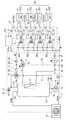
以下、本発明の第1実施形態による貯湯式給湯装置を図1に基づいて説明する。図1は貯湯タンク10に給湯水を蓄える給湯器システムに多機能ヘッダーのうち給湯ヘッダー40のみを一体に構成させて本発明を適用したものであり、貯湯式給湯装置の全体構成を示す模式図である。(First embodiment)
Hereinafter, a hot water storage type hot water supply apparatus according to a first embodiment of the present invention will be described with reference to FIG. FIG. 1 is a schematic view showing an overall configuration of a hot water storage type hot water supply apparatus in which only the hot
本実施形態の貯湯式給湯装置は、図1に示すように、給湯水を蓄える貯湯タンク10と、ヒートポンプサイクルからなり貯湯タンク10内の給湯水を循環させて沸き上げ運転する熱源装置であるヒートポンプユニット20と、貯湯タンク10から供給される給湯水(温水)と給水配管である導入管11から供給される水道水(冷水)とを混合して給湯栓60に供給する湯水混合手段50を複数有する多機能ヘッダー装置である給湯ヘッダー40と、貯湯タンク10に蓄えられた給湯水を給湯ヘッダー40に供給する給湯水供給回路30と、制御装置200から構成されている。 As shown in FIG. 1, the hot water storage type hot water supply apparatus of the present embodiment is a
貯湯タンク10は、耐食性に優れた金属製(例えば、ステンレス製)のタンクであり、外周部に図示しない断熱材が配置されており、高温の給湯水を長時間に渡って保温することができるようになっている。また、貯湯タンク10は縦長形状であり、その底面には導入口10aが設けられ、この導入口10aには貯湯タンク10内に水道水を導入する給水配管である導入管11が接続されている。この導入管11には温度検出手段である給水サーミスタ12が設けられており、導入管11内の温度情報を後述する制御装置200に出力するようになっている。 The hot
また、導入管11には導入される水道水の水圧が所定圧となるように調節するとともに、断水などにおける湯の逆流を防止する減圧逆止弁13が設けられている。そして、導入管11の給水サーミスタ12および減圧逆止弁13が設けられた位置より下流の給水分岐点11aと後述する混合弁15とはバイパス経路である給水配管14により繋がれている。 In addition, the
一方、貯湯タンク10の最上部には導出口10bが設けられ、この導出口10bには貯湯タンク10内の湯を導出するための給湯経路である導出管16が接続されている。導出管16の経路途中には逃がし弁17が配設された排出配管18を接続しており、貯湯タンク10内の圧力が所定圧以上に上昇した場合には、貯湯タンク10内の湯を外部に排出して、貯湯タンク10等にダメージを与えないようになっている。 On the other hand, a lead-out
15は湯水混合手段である混合弁であり、導出管16と給水配管14との合流点に配置されている。この混合弁15は、サーモワックスが内蔵された温調用混合弁であって、ここでは、貯湯タンク10から供給される給湯水(温水)と、給水配管14から供給される水道水(冷水)とを混合させて、混合弁15の出口側の湯温が所定温度(例えば、60℃程度)になるようにしている。 A
また、混合弁15の出口側は後述する第1分岐点30aと接続される給湯配管16aが接続されており、この給湯配管16aには流量カウンタ19が設けられており、この流量カウンタ19は給湯配管16a内の流量情報を後述する制御装置200に出力するようになっている。なお、流量カウンタ19が給湯配管16a内の水の流れを検出したときには、後述する複数の給湯栓60のうち、いずれか一つの給湯栓60a〜60dが開弁されており出湯状態である。 The outlet side of the mixing
一方、貯湯タンク10の下部には、貯湯タンク10内の水を吸入するための吸入口10cが設けられ、貯湯タンク10の上部には、貯湯タンク10内に湯を吐出する吐出口10dが設けられている。吸入口10cと吐出口10dとは循環回路21で接続されており、循環回路21の一部は熱源装置であるヒートポンプユニット20内に配置されている。 On the other hand, a
また、循環回路21のヒートポンプユニット20内に配置された部分には、図示しない熱交換器が設けられており、吸入口10cから吸入した貯湯タンク10内の水を高温冷媒との熱交換により加熱し、吐出口10dから貯湯タンク10内に戻すことにより貯湯タンク10内の水を沸き上げることができるようになっている。 Further, a heat exchanger (not shown) is provided in a portion of the
なお、本実施形態のヒートポンプユニット20は、図示しない圧縮機、凝縮器、減圧器、蒸発器などのヒートポンプサイクルを構成する冷媒機能部品からなる超臨界ヒートポンプである。この超臨界ヒートポンプとは、高圧側の冷媒圧力が冷媒の臨界圧力以上となるヒートポンプサイクルを言い、例えば、二酸化炭素、エチレン、エタン、酸化窒素などを冷媒とするヒートポンプサイクルである。 In addition, the
因みに、超臨界ヒートポンプによれば、一般的なヒートポンプサイクルよりも高温(例えば、85℃〜90℃程度)の給湯水を沸き上げることができる。また、ヒートポンプユニット20は後述する制御装置200からの制御信号により作動するとともに、作動状態を制御装置200に出力するようになっている。 Incidentally, according to the supercritical heat pump, hot water can be boiled at a higher temperature (for example, about 85 ° C. to 90 ° C.) than a general heat pump cycle. The
さらに、貯湯タンク10の上部外壁面には、貯湯タンク10内上部の水温を検出する出湯サーミスタ(図示しない)が設けられており、導出口10bから導出される水の温度情報を後述する制御装置200に出力するようになっている。また、貯湯タンク10の外壁面には、図示しない複数の水位サーミスタが縦方向にほぼ等間隔に配置され、貯湯タンク10内に満たされた水の各水位レベルでの温度情報を後述する制御装置200に出力するようになっている。従って、後述する制御装置200は、図示しない水位サーミスタからの温度情報に基づいて、貯湯タンク10内上方の沸き上げられた湯と貯湯タンク10内下方の沸き上げられる前の水との温度境界位置を検出できるようになっている。 Further, a hot water thermistor (not shown) for detecting the water temperature in the upper part of the hot
次に、給湯ヘッダー40は、混合弁15から供給される給湯水(温水)と給水配管である導入管11から供給される水道水(冷水)とを混合して給湯栓60(図示例では60a〜60d)に供給する装置であって、図示のように、複数の湯水混合手段50(図示例では50a〜50d)から構成されている。 Next, the hot
各々の湯水混合手段50は、貯湯タンク10から後述する給湯水供給回路30を介して供給される給湯水(温水)と導入管11から供給される水道水(冷水)とを混合する混合弁51と、この混合弁51で混合された湯水の出湯流量を調節する流量調節手段52と、この流量調節手段52の下流に設けられて、出湯流量および出湯温度を検出するフィードバックセンサ53と、混合弁51および流量調節手段52の動作を制御する弁制御装置54とを主要部として構成されている。 Each hot water mixing means 50 mixes hot water (hot water) supplied from the hot
つまり、混合弁51で混合された湯水が流量調節手段52およびフィードバックセンサ53により設定温度に調節された給湯水が出湯用の配管55を経て給湯栓60に供給可能とされている。なお、本実施形態の混合弁51は、弁制御装置54からの制御信号に基づいて、給湯水供給回路30から給湯水(温水)と導入管11から供給される水道水(冷水)との混合比率を設定する弁装置であって、給湯水(温水)と水道水(冷水)との混合比率を調節することにより設定温度の湯水を得るように構成されている。また、流量調節手段52は、弁制御装置54からの制御信号に基づいて弁の開度を設定する弁装置であって、弁の開度を調節することにより所望の設定流量の出湯を行なうように構成している。 In other words, hot water mixed with the mixing
また、弁制御装置54は、混合弁51および流量調節手段52に対して制御信号を出力可能に構成されたマイクロコンピュータであって、図示しない通信線を介してこれら混合弁51および流量調節手段52と電気的に接続されている。さらに、弁制御装置54には、フィードバックセンサ53も同様に図示しない通信線を介して電気的に接続されおり、フィードバックセンサ53で検出される出湯流量や出湯温度の温度、流量情報が弁制御装置54に取り込み可能とされている。 The
そして、弁制御装置54は、図示のように給湯栓60の操作パネル61と図示しない通信線を介して接続され、この操作パネル61で設定される設定温度や出湯流量の設定情報の取り込みも可能とされている。なお、給湯栓60は、台所や浴室のカラン,シャワーのように湯水の出湯を行なうことがある水栓であって、ここでは、上述したように各給湯栓60には湯水混合手段50から湯水が供給されるので、給湯栓60には温水と冷水を混合する機能を持たない単水栓が用いられている。 The
また、給湯栓60には、それぞれ設定温度や出湯流量などを設定するための操作パネル61が備えられており、この操作パネル61と弁制御装置54とが電気的に接続され、操作パネル61で操作された操作信号が弁制御装置54に入力されるように構成されている。なお、図示例では、60aが洗面所のカラン、60bが浴室(浴槽用)のカラン、60cがシャワー、60dが台所のカランを示している。 The
次に、本発明の要部である給湯水供給回路30について説明する。この給湯水供給回路30は、複数の給湯栓60すべてが閉弁されたとき、つまり、出湯待機中に、給湯ヘッダー40に供給される給湯水が所定温度(例えば、60℃程度)以下とならないように保温を行なうための循環回路である。 Next, the hot
具体的には、第1分岐点30a、混合弁51の一方側に連通する温水側入口30b、逆止弁32、循環ポンプ33、第1熱交換器31、三方弁34、第1分岐点30aの順に、環状に循環する回路、循環ポンプ33と第1熱交換器31との間に設けられた第2分岐点30cと三方弁34とを接続するバイパス回路35および第1分岐点30aと温水側入口30bとの間に給湯サーミスタ36を構成している。 Specifically, the
第1熱交換器31は貯湯タンク10内の上方に配設され、給湯水供給回路30内の給湯水を加熱するための水−水熱交換器であって、ヒートポンプユニット2により沸き上げられた給湯水の熱量を熱源としている。循環ポンプ33は電動ポンプであり、後述する制御装置200により制御され、複数の給湯栓60すべてが閉弁される出湯待機中に、給湯水の湯温の検出と、検出された湯温が所定温度以下(例えば、60℃程度)のときに、作動するように制御される。 The
三方弁34は、図中に示す矢印aまたは矢印bのいずれか一方の流れ方向に切り換える切換弁であり、後述する制御装置200により制御され、給湯サーミスタ36より検出された湯温に基づいて流れ方向が制御される。また、給湯サーミスタ36は、給湯ヘッダー40に供給される給湯水の湯温を検出する温度センサであり、後述する制御装置200に温度情報を出力するようにしている。 The three-
ところで、給湯ヘッダー40に供給される給湯水は、複数の給湯栓60すべてが閉弁される出湯待機中においては、給湯水供給回路30内で停滞しており、湯温が順次低下してしまう。そこで、本発明では、この出湯待機中に、循環ポンプ33を所定時間毎に作動させて給湯水供給回路30内の給湯水の湯温を検出するとともに、給湯水の湯温が所定温度(例えば、60℃程度)以下のときは、三方弁34を矢印b側に切り換えて、給湯水供給回路30内の給湯水を第1熱交換器31側に循環させるようにしている。これにより、給湯水供給回路30内の給湯水が所定温度(例えば、60℃程度)以上に保温されることになる。 By the way, the hot water supplied to the hot
制御装置200は、上述したヒートポンプユニット20、各々の湯水混合手段50、および給湯水供給回路30内の循環ポンプ33、三方弁34などを制御するマイクロコンピュータであって、ヒートポンプユニット20に内蔵されるヒートポンプユニット制御用のマイクロコンピュータ(図示せず)および各弁制御装置54に電気的に接続されている。また、上述したように、制御装置200は、給水サーミスタ12および給湯サーミスタ36からの温度情報が取得可能とされている。 The
次に、上記構成による貯湯式給湯装置の作動について説明する。まず、図示しない電源スイッチがオンされると、制御装置200は、ヒートポンプユニット20を制御させて通常の温調給湯制御を行なう。この温調給湯制御が実行されると、制御装置200は、貯湯タンク10に設けられた各サーミスタ(図示せず)からの温度情報等や、図示しない操作盤により設定された時刻情報等に基づいて、適宜ヒートポンプサイクル20を作動させ貯湯タンク10内の水を加熱して高温(例えば85℃の湯)の給湯水を蓄えておく。 Next, the operation of the hot water storage type hot water supply apparatus having the above configuration will be described. First, when a power switch (not shown) is turned on, the
そして、複数の給湯栓60のいずれかが開弁されると、混合弁15により貯湯タンク10から供給される高温の給湯水と導入管11から供給される水道水とを混合させて所定温度(例えば、60℃程度)の給湯水が湯水混合手段50に供給される。 When any of the plurality of hot water taps 60 is opened, the hot water supplied from the hot
そして、湯水混合手段50では、給湯栓60の操作パネル61にて設定された設定温度、設定流量と、フィードバックセンサ53により検出された温度、流量情報とに基づいて、混合弁51および流量調整手段52が制御されて所望する出湯が得られる。ここで、混合弁51は、給湯水供給回路30から供給される給湯水(温水)と導入管11から供給される水道水(冷水)との混合の湯水である。 In the hot water / mixing means 50, the mixing
ところで、複数の給湯栓60のすべてが閉弁される出湯待機中は、混合手段50に供給される給湯水が給湯水供給回路30内で停滞してしまう。そこで、本発明では、この出湯待機中に、循環ポンプ33を所定時間毎に作動させて給湯水供給回路30内の給湯水の湯温を検出するとともに、給湯水の湯温が所定温度(例えば、60℃程度)以下のときは、三方弁34を矢印b側に切り換えて、給湯水供給回路30内の給湯水を第1熱交換器31側に循環させることで、混合手段50に供給される給湯水が所定温度(例えば、60℃程度)以上に保温されることになる。 By the way, hot water supplied to the mixing means 50 stagnates in the hot
これにより、出湯待機中に給湯水供給回路30内に停滞する給湯水は保温されているので、いずれかの給湯栓60が開弁されたときであっても常時湯水混合手段50に供給される給湯水は一定の湯温の給湯水が供給される。従って、設定温度に達するまでの湯待ち時間および捨て水の低減が図れるものである。 As a result, the hot water staying in the hot
以上の第1実施形態の貯湯式給湯装置によれば、給湯栓60のすべてが閉弁されている出湯待機中に、湯水混合手段50に供給される貯湯タンク10からの給湯水が所定温度(例えば、60℃程度)以上に保温されるように構成したことにより、給湯栓60開弁後、直ちに湯水混合手段50により設定温度の湯温に混合された給湯水が給湯栓60に供給されるため、湯待ち時間および捨て水の低減が図れる。 According to the hot water storage type hot water supply apparatus of the first embodiment described above, hot water supplied from the hot
また、貯湯タンク10内に第1熱交換器31を配設し、給湯水供給回路30内の給湯水をこの第1熱交換器31に循環させて保温するように構成したことにより、貯湯タンク10内の給湯水を湯水混合手段50に供給される給湯水の保温のための熱源として利用できるため、別体のパイプヒータなどの加熱手段を必要とせず保温のためのランニングコストが低減できる。 Further, the
また、本実施形態のヒートポンプユニット20は、冷媒が二酸化炭素であることにより、二酸化炭素を用いと、超臨界ヒートポンプサイクルであるため、貯湯タンク10に蓄えられる給湯水を高温(例えば、85〜90℃程度)にすることができるとともに、周知のフロン、代替フロンの冷媒を用いたヒートポンプサイクルよりも経済性が優れる。 Moreover, since the
(第2実施形態)
以上の第1実施形態では、多機能ヘッダーである給湯ヘッダー40を給湯水供給回路30で保温した給湯水を複数の湯水混合手段50に供給させるように構成したが、これに限らず、給湯機能の他に、給湯水供給回路30で保温した給湯水を熱媒体に変換して暖房用放熱器に供給する暖房機能を一体に構成しても良い。具体的には、図2に示すように、給湯機能の他に、暖房機能として床暖房機能を付加したもので、このときには、給湯水供給回路30で保温した給湯水を熱源とする暖房熱源手段70を機能ヘッダーとして給湯ヘッダー40に一体に構成させている。(Second Embodiment)
In the first embodiment described above, the hot
因みに、本実施形態の暖房熱源手段70は、給湯水供給回路30で保温した給湯水と熱媒体とが熱交換する第2熱交換器71、上記給湯水の第2熱交換器71への流通を開閉する一次側電磁弁72、熱媒体を暖房用放熱器である床暖房用放熱器80に循環させる循環ポンプ73、および熱媒体の循環流量を調節する流量調整弁74から構成されている。従って、床暖房放熱器80は配管75を介して熱媒体が循環されるように構成されている。なお、図中81は操作パネルであり、76は床暖房用制御装置であり、制御装置200と電気的に接続されている。これにより、暖房熱源手段70は、給湯水供給回路30で保温した給湯水が第2熱交換器71に供給され、この給湯水と熱交換された熱媒体が床暖房用放熱器80に供給されることで床暖房が可能となる。 Incidentally, the heating heat source means 70 of the present embodiment distributes the hot water supplied to the second heat exchanger 71 and the second heat exchanger 71 for exchanging heat between the hot water kept in the hot
以上の構成による貯湯式給湯装置によれば、湯水混合手段50の他に、暖房熱源手段70が一体に構成されたことにより、貯湯タンク10内の給湯水を床暖房用放熱器80の熱源として利用できるため、給湯機能の他に給湯装置の多機能化が図れる。しかも、湯水混合手段50と一体に構成したことで暖房機能が併設されても給湯装置回りの配管の単純化が図れる。 According to the hot water storage type hot water supply apparatus having the above configuration, the heating heat source means 70 is integrally configured in addition to the hot water mixing means 50, so that hot water in the hot
さらに、上述した給湯機能、暖房機能の他に、浴水の追い焚き機能を一体に構成しても良い。具体的には、図2に示すように、湯水混合手段50および暖房熱源手段70の他に、浴水を循環させて追い焚きする浴水追い焚き手段90を一体に構成させている。このときには、浴水追い焚き手段90を機能ヘッダーとして給湯ヘッダー40に一体に構成させている。 Furthermore, in addition to the hot water supply function and the heating function described above, a bath water replenishing function may be integrated. Specifically, as shown in FIG. 2, in addition to the hot water mixing means 50 and the heating heat source means 70, a bath water replenishing means 90 that circulates and regenerates the bath water is integrally configured. At this time, the bath water replenishing means 90 is integrated with the hot
因みに、浴水追い焚き手段90は、給湯水供給回路30で保温した給湯水と浴水とが熱交換する第3熱交換器91、上記給湯水の第3熱交換器91への流通を開閉する一次側電磁弁92、および浴槽内の浴水を第3熱交換器91に循環させる循環ポンプ93、および水温サーミスタ94から構成されている。なお、図中95は操作パネルであり、96は追い焚き用制御装置であり、制御装置200と電気的に接続されている。 Incidentally, the bath water replenishing means 90 opens and closes the flow of the hot water supplied to the hot
以上の構成による浴水追い焚き手段90によれば、給湯水供給回路30で保温した給湯水が第3熱交換器91に供給され、この給湯水と熱交換された浴水の追い焚きが可能となる。従って、湯水混合手段50、暖房熱源手段70の他、浴水追い焚き手段90が一体に構成されたことにより、上記同様に、貯湯タンク10内の給湯水を浴水追い焚き手段90の熱源として利用できるため、給湯機能、暖房機能の他に給湯装置の多機能化が図れる。 According to the bath water replenishing means 90 having the above-described configuration, the hot water maintained by the hot
(他の実施形態)
以上の実施形態では、給湯水供給回路30内に三方弁34を配設させたが、これに限らず、第1分岐点30aの上流側に設けられた混合弁15を配設させても良い。なお、第1分岐点30aの上流側に設けられた混合弁15は、以上の実施形態ではサーモワックスが内蔵する固定式の温調混合弁を用いたが、これに限らず、混合弁51と同じ方式のものでも良い。また、以上の実施形態では所定温度を60℃程度としたがこの数字に限定するものではない。(Other embodiments)
In the above embodiment, the three-
また、以上の実施形態では、冷媒に二酸化炭素を用いたヒートポンプユニット20を熱源装置として説明したが、これに限らず、フロン、代替フロンなどの冷媒を用いる一般的なヒートポンプサイクルでも良い。 In the above embodiment, the
10…貯湯タンク
20…ヒートポンプユニット(熱源装置)
30…給湯水供給回路
31…第1熱交換器
40…給湯ヘッダー(多機能ヘッダー装置)
50…湯水混合手段
60…給湯栓
70…暖房熱源手段
80…床暖房用放熱器(暖房用放熱器)
90…追い焚き手段10 ... Hot
30 ... Hot
50 ... Hot water mixing means 60 ... Hot water tap 70 ... Heating heat source means 80 ... Floor heating radiator (heating radiator)
90 ... Repulse means
Claims (5)
Translated fromJapaneseヒートポンプサイクルからなり前記貯湯タンク(10)内の給湯水を循環させて沸き上げ運転する熱源装置(20)と、
前記貯湯タンク(10)から供給される給湯水と給水配管から供給される冷水とを混合して給湯栓(60)に供給する湯水混合手段(50)を複数有する多機能ヘッダー装置(40)と、
前記貯湯タンク(10)に蓄えられた給湯水を前記多機能ヘッダー装置(40)に供給する給湯水供給回路(30)と、
前記湯水混合手段(50)の上流側において前記給湯水回路(30)から分岐し、前記貯湯タンク(10)から供給される給湯水を熱媒体と熱交換させる放熱器(80)に供給し、前記湯水混合手段(50)の上流側で前記放熱器(10)を通過した給湯水を前記給湯水回路(30)に戻す加熱用熱源手段(70)とを備える貯湯式給湯装置であって、
前記加熱用熱源手段(70)は前記多機能ヘッダー装置(40)に一体に構成されており、
前記給湯水供給回路(30)は、前記給湯栓(60)が閉弁されている出湯待機中に、前記多機能ヘッダー装置(40)に供給される前記貯湯タンク(10)からの給湯水が所定温度以上に保温されるように構成したことを特徴とする貯湯式給湯装置。A hot water storage tank (10) for storing hot water,
A heat source device (20) that comprises a heat pump cycle and circulates hot water in the hot water storage tank (10) to perform a boiling operation;
A multi-function header device (40) having a plurality of hot water mixing means (50) for mixing hot water supplied from the hot water storage tank (10) and cold water supplied from a water supply pipe and supplying the hot water to the hot water tap (60); ,
A hot water supply circuit (30) for supplying hot water stored in the hot water storage tank (10) to the multi-function header device (40);
Branching from the hot water supply circuit (30) upstream of the hot water mixing means (50) and supplying hot water supplied from the hot water storage tank (10) to a radiator (80) for exchanging heat with a heat medium; A hot water storage type hot water supply devicecomprising heating source means (70) for returning hot water passing through the radiator (10) upstream of the hot water mixing means (50) to the hot water circuit (30) ,
The heating heat source means (70) is integrally formed with the multifunction header device (40),
The hot water supply circuit (30) is configured to receive hot water from the hot water storage tank (10) supplied to the multi-function header device (40) during a hot water supply waiting time in which the hot water tap (60) is closed. A hot water storage type hot water supply apparatus configured to be kept at a predetermined temperature or more.
Priority Applications (1)
| Application Number | Priority Date | Filing Date | Title |
|---|---|---|---|
| JP2003370982AJP4155162B2 (en) | 2003-10-30 | 2003-10-30 | Hot water storage water heater |
Applications Claiming Priority (1)
| Application Number | Priority Date | Filing Date | Title |
|---|---|---|---|
| JP2003370982AJP4155162B2 (en) | 2003-10-30 | 2003-10-30 | Hot water storage water heater |
Publications (2)
| Publication Number | Publication Date |
|---|---|
| JP2005134041A JP2005134041A (en) | 2005-05-26 |
| JP4155162B2true JP4155162B2 (en) | 2008-09-24 |
Family
ID=34647819
Family Applications (1)
| Application Number | Title | Priority Date | Filing Date |
|---|---|---|---|
| JP2003370982AExpired - Fee RelatedJP4155162B2 (en) | 2003-10-30 | 2003-10-30 | Hot water storage water heater |
Country Status (1)
| Country | Link |
|---|---|
| JP (1) | JP4155162B2 (en) |
Cited By (1)
| Publication number | Priority date | Publication date | Assignee | Title |
|---|---|---|---|---|
| CN102410597A (en)* | 2011-10-25 | 2012-04-11 | 天津大学 | Ground source heat pump air conditioning system device and its control and operation method based on peak shaving energy storage |
Families Citing this family (3)
| Publication number | Priority date | Publication date | Assignee | Title |
|---|---|---|---|---|
| JP4840642B2 (en)* | 2005-11-30 | 2011-12-21 | 株式会社ノーリツ | Liquid heating device |
| JP4925983B2 (en)* | 2007-09-19 | 2012-05-09 | 三菱電機株式会社 | Hot water system |
| JP7674950B2 (en)* | 2021-08-02 | 2025-05-12 | リンナイ株式会社 | Instant hot water system |
- 2003
- 2003-10-30JPJP2003370982Apatent/JP4155162B2/ennot_activeExpired - Fee Related
Cited By (2)
| Publication number | Priority date | Publication date | Assignee | Title |
|---|---|---|---|---|
| CN102410597A (en)* | 2011-10-25 | 2012-04-11 | 天津大学 | Ground source heat pump air conditioning system device and its control and operation method based on peak shaving energy storage |
| CN102410597B (en)* | 2011-10-25 | 2014-05-07 | 天津大学 | Ground source heat pump air-conditioning system device based on peak regulation and energy storage as well as control and operation method thereof |
Also Published As
| Publication number | Publication date |
|---|---|
| JP2005134041A (en) | 2005-05-26 |
Similar Documents
| Publication | Publication Date | Title |
|---|---|---|
| JP5109300B2 (en) | Hot water storage hot water heater | |
| JP4124258B2 (en) | Heat pump water heater | |
| JP4407643B2 (en) | Hot water storage water heater | |
| JP5436933B2 (en) | Hot water system | |
| JP5245217B2 (en) | Hot water storage hot water heater | |
| JP3887781B2 (en) | Heat pump water heater | |
| JP2008039340A (en) | Water heater | |
| JP2004101134A (en) | Hot water storage type hot-water feeder | |
| JP4893165B2 (en) | Heat pump type water heater | |
| JP4155162B2 (en) | Hot water storage water heater | |
| JP3868909B2 (en) | Hot water storage water heater | |
| JP2012237492A (en) | Storage type water heater | |
| JP3888117B2 (en) | Hot water storage water heater | |
| JP2005147557A (en) | Hot water supply apparatus | |
| JP5023607B2 (en) | Hot water supply apparatus and control method thereof | |
| JP3869426B2 (en) | Hot water storage water heater | |
| JP2004116889A (en) | Hot water storage-type hot water supply device | |
| JP4448488B2 (en) | Hot water storage water heater | |
| JP5979042B2 (en) | Water heater | |
| JP4207867B2 (en) | Hot water storage water heater | |
| JP2005009747A (en) | Hot water storage water heater | |
| JP2004293837A (en) | Hot-water storage type hot-water supply device | |
| JP2008008563A (en) | Storage type hot-water supply method and storage type hot-water supply device | |
| JP4155140B2 (en) | Hot water storage water heater | |
| JP2004116890A (en) | Hot water storage-type hot water supply device |
Legal Events
| Date | Code | Title | Description |
|---|---|---|---|
| A621 | Written request for application examination | Free format text:JAPANESE INTERMEDIATE CODE: A621 Effective date:20060208 | |
| A977 | Report on retrieval | Free format text:JAPANESE INTERMEDIATE CODE: A971007 Effective date:20071126 | |
| A131 | Notification of reasons for refusal | Free format text:JAPANESE INTERMEDIATE CODE: A131 Effective date:20071211 | |
| A521 | Request for written amendment filed | Free format text:JAPANESE INTERMEDIATE CODE: A523 Effective date:20080208 | |
| A02 | Decision of refusal | Free format text:JAPANESE INTERMEDIATE CODE: A02 Effective date:20080318 | |
| A521 | Request for written amendment filed | Free format text:JAPANESE INTERMEDIATE CODE: A523 Effective date:20080513 | |
| A911 | Transfer to examiner for re-examination before appeal (zenchi) | Free format text:JAPANESE INTERMEDIATE CODE: A911 Effective date:20080529 | |
| TRDD | Decision of grant or rejection written | ||
| A01 | Written decision to grant a patent or to grant a registration (utility model) | Free format text:JAPANESE INTERMEDIATE CODE: A01 Effective date:20080617 | |
| A01 | Written decision to grant a patent or to grant a registration (utility model) | Free format text:JAPANESE INTERMEDIATE CODE: A01 | |
| A61 | First payment of annual fees (during grant procedure) | Free format text:JAPANESE INTERMEDIATE CODE: A61 Effective date:20080630 | |
| FPAY | Renewal fee payment (event date is renewal date of database) | Free format text:PAYMENT UNTIL: 20110718 Year of fee payment:3 | |
| R150 | Certificate of patent or registration of utility model | Free format text:JAPANESE INTERMEDIATE CODE: R150 | |
| FPAY | Renewal fee payment (event date is renewal date of database) | Free format text:PAYMENT UNTIL: 20120718 Year of fee payment:4 | |
| FPAY | Renewal fee payment (event date is renewal date of database) | Free format text:PAYMENT UNTIL: 20120718 Year of fee payment:4 | |
| FPAY | Renewal fee payment (event date is renewal date of database) | Free format text:PAYMENT UNTIL: 20130718 Year of fee payment:5 | |
| LAPS | Cancellation because of no payment of annual fees |