JP4153931B2 - Keyboard unit and electronic device equipped with keyboard unit - Google Patents
Keyboard unit and electronic device equipped with keyboard unitDownload PDFInfo
- Publication number
- JP4153931B2 JP4153931B2JP2005216012AJP2005216012AJP4153931B2JP 4153931 B2JP4153931 B2JP 4153931B2JP 2005216012 AJP2005216012 AJP 2005216012AJP 2005216012 AJP2005216012 AJP 2005216012AJP 4153931 B2JP4153931 B2JP 4153931B2
- Authority
- JP
- Japan
- Prior art keywords
- key
- keyboard
- character
- keyboard unit
- base
- Prior art date
- Legal status (The legal status is an assumption and is not a legal conclusion. Google has not performed a legal analysis and makes no representation as to the accuracy of the status listed.)
- Expired - Lifetime
Links
Images


Classifications
- G—PHYSICS
- G06—COMPUTING OR CALCULATING; COUNTING
- G06F—ELECTRIC DIGITAL DATA PROCESSING
- G06F1/00—Details not covered by groups G06F3/00 - G06F13/00 and G06F21/00
- G06F1/16—Constructional details or arrangements
- G06F1/1613—Constructional details or arrangements for portable computers
- G06F1/1633—Constructional details or arrangements of portable computers not specific to the type of enclosures covered by groups G06F1/1615 - G06F1/1626
- G06F1/1662—Details related to the integrated keyboard
- G—PHYSICS
- G06—COMPUTING OR CALCULATING; COUNTING
- G06F—ELECTRIC DIGITAL DATA PROCESSING
- G06F1/00—Details not covered by groups G06F3/00 - G06F13/00 and G06F21/00
- G06F1/16—Constructional details or arrangements
- G06F1/1613—Constructional details or arrangements for portable computers
- G06F1/1615—Constructional details or arrangements for portable computers with several enclosures having relative motions, each enclosure supporting at least one I/O or computing function
- G06F1/1616—Constructional details or arrangements for portable computers with several enclosures having relative motions, each enclosure supporting at least one I/O or computing function with folding flat displays, e.g. laptop computers or notebooks having a clamshell configuration, with body parts pivoting to an open position around an axis parallel to the plane they define in closed position
- G—PHYSICS
- G06—COMPUTING OR CALCULATING; COUNTING
- G06F—ELECTRIC DIGITAL DATA PROCESSING
- G06F1/00—Details not covered by groups G06F3/00 - G06F13/00 and G06F21/00
- G06F1/16—Constructional details or arrangements
- G06F1/1613—Constructional details or arrangements for portable computers
- G06F1/1633—Constructional details or arrangements of portable computers not specific to the type of enclosures covered by groups G06F1/1615 - G06F1/1626
- G06F1/1656—Details related to functional adaptations of the enclosure, e.g. to provide protection against EMI, shock, water, or to host detachable peripherals like a mouse or removable expansions units like PCMCIA cards, or to provide access to internal components for maintenance or to removable storage supports like CDs or DVDs, or to mechanically mount accessories
- G06F1/166—Details related to functional adaptations of the enclosure, e.g. to provide protection against EMI, shock, water, or to host detachable peripherals like a mouse or removable expansions units like PCMCIA cards, or to provide access to internal components for maintenance or to removable storage supports like CDs or DVDs, or to mechanically mount accessories related to integrated arrangements for adjusting the position of the main body with respect to the supporting surface, e.g. legs for adjusting the tilt angle
Landscapes
- Engineering & Computer Science (AREA)
- Computer Hardware Design (AREA)
- Theoretical Computer Science (AREA)
- Physics & Mathematics (AREA)
- General Engineering & Computer Science (AREA)
- Human Computer Interaction (AREA)
- General Physics & Mathematics (AREA)
- Mathematical Physics (AREA)
- Input From Keyboards Or The Like (AREA)
- Push-Button Switches (AREA)
Description
Translated fromJapanese本発明は、キートップを有するキーボードユニットおよびキーボードユニットを備えた電子機器に関する。 The present invention relates to a keyboard unit having a key top and an electronic device including the keyboard unit.
従来、故障の原因が水没に起因することを確認できるようにした携帯電話機が知られている。この携帯電話機は、筐体と、筐体に収容された回路板と、筐体の切欠部から突出したキーと、水没を検知する水没ラベルと、を備えている。キーは、弾力のあるドーム形状のもので構成され、回路板に固定されている。キーと回路板との固定部分の間に、水没ラベルが配置されている。この水没ラベルには、水溶性インクが印刷されている。水没ラベルに水がかかると、水溶性インクが水没ラベルの表面に滲むため、携帯電話機が水没した事実が確認できる(例えば、特許文献1参照)。 2. Description of the Related Art Conventionally, a mobile phone that can confirm that a cause of failure is caused by submergence is known. This mobile phone includes a housing, a circuit board accommodated in the housing, a key protruding from the cutout portion of the housing, and a submerged label for detecting submersion. The key is made of an elastic dome shape and is fixed to the circuit board. A submerged label is disposed between the fixed part of the key and the circuit board. Water-soluble ink is printed on the submerged label. When water is applied to the submerged label, water-soluble ink oozes on the surface of the submerged label, so that the fact that the mobile phone has been submerged can be confirmed (for example, see Patent Document 1).
ところで、ポータブルコンピュータのような電子機器に搭載されるキーボードは、携帯電話機のキーとは異なる構成のキーを採用している。すなわち、電子機器のキーは、キートップと、キートップを昇降自在に支持する支持手段とを有している。キートップの押し下げにより、所望の情報をポータブルコンピュータに入力できる。
上記従来の携帯電話機に採用されている水没ラベルを電子機器に適用すると、キーボード内部あるいは筐体内部にまで相当量の水が浸入することで検知されることとなり、水が少量であったりした場合、検知できない場合もありえる。例えば電子機器、あるいはキーボードが故障した場合、故障原因が浸水によるものなのか否か判断が難しくなる。 When the submerged label used in the above-mentioned conventional mobile phone is applied to an electronic device, it will be detected when a considerable amount of water enters the keyboard or the case, and there is a small amount of water. , It may not be detected. For example, when an electronic device or a keyboard breaks down, it is difficult to determine whether the cause of the failure is due to water immersion.
本発明の目的は、容易に浸水を検知することができるキーボードと電子機器を得ることにある。 The objective of this invention is obtaining the keyboard and electronic device which can detect a flood easily.
前記目的を達成するため、本発明の一つの形態に係るキーボードユニットは、ベースと、ベースの上面に設けられるとともにキートップを有する文字キー群および機能キー群と、を含むキーボード本体と、文字キー群および前記機能キー群のキートップの下方で、ベースの上面においてキートップの縁で囲まれる領域に設けられるとともに浸水を検知する検知手段と、を具備することを特徴とする。To achieve the above object, a keyboard unit according to one aspect of the present inventionincludes a keyboard bodyincludinga base, acharacter key group and a function key groupprovided on the upper surface of the base and having a key top, and acharacter key. And detecting means for detecting water ingress in the region surrounded by the edgeof the key topon the upper surface of the base below the key top of thegroup and the function key group .
前記目的を達成するため、本発明の一つの形態に係る電子機器は、ディスプレイと、前記ディスプレイが取り付けられるとともに、キーボード支持部を有する筐体と、キーボード支持部に支持されたキーボードユニットと、を具備し、キーボードユニットは、ベースと、ベースの上面に設けられるとともにキートップを有する文字キー群および機能キー群と、を含むキーボード本体と、文字キー群および機能キー群のキートップの下方で、ベースの上面においてキートップの縁で囲まれる領域に設けられるとともに浸水を検知する検知手段と、を具備することを特徴とする。
In order to achieve the above object, an electronic apparatus according to an aspect of the present invention includes adisplay, a housing to which thedisplay is attached , a keyboard support portion, and a keyboard unit supported by the keyboard support portion. The keyboard unit includes abase,a keyboard bodyincluding acharacter key group and a function key groupprovided on the upper surface of the base and having a key top, and below the key tops of thecharacter key group and the function key group. It is provided in the area | region enclosed by the edge ofa keytop in the upper surface of a base, and comprises the detection means which detects water immersion.
本発明によれば、容易に浸水を検知することができるキーボードと電子機器を提供することができる。 ADVANTAGE OF THE INVENTION According to this invention, the keyboard and electronic device which can detect a flood easily can be provided.
以下に、図1から図8を参照して、本発明の電子機器の第1の実施形態について説明する。 Hereinafter, a first embodiment of the electronic apparatus of the present invention will be described with reference to FIGS.
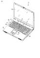
図1に示すように、電子機器の一例であるポータブルコンピュータ11は、筐体12、ディスプレイ13、タッチパッド14、およびキーボードユニット15、を備えている。筐体12は、上面にキーボード支持部21を有している。図7に示すように、キーボード支持部21は、筐体12の上方に向かって開放するような凹部あるいは開口部であり、上記キーボードユニット15を支持している。 As shown in FIG. 1, a
図7に示すように、筐体12の下面に、脚部23が設けられている。脚部23は、例えばポータブルコンピュータ11を机の天板22の上に置いたときに、天板22に接触する。これにより、キーボードユニット15は、手前が低くなる姿勢に傾斜しており、キーボードユニット15の操作性が高められている。 As shown in FIG. 7,
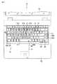
図2および図3に示すように、キーボードユニット15は、一般的なキー配列を有するもので構成されている。キーボードユニット15は、キーボード本体26、および検知手段27を有している。 As shown in FIGS. 2 and 3, the
キーボード本体26は、ベース30と、複数の文字キーを有する文字キー群31と、文字キーよりもキートップ41の面積が大きい他のキーを複数有する機能キー群32、を含んでいる。ベース30は、筐体12のキーボード支持部21にきっちりと嵌まり込むような大きさを有する板状をなしている。図4に示すように、ベース30は、金属製の補強板33と、補強板33の表面を被い柔軟性を有するカバー34と、フィルム状の回路基板35と、を備えている。ベース30は、中央部Sがわずかに低くなるようにその周囲が反っている。このため、ベース30をキーボード支持部21に固定する際に、ベース30の四隅をねじ止めしても、キーボード本体26の中央部Sが盛り上がるのが防止される。 The
図2に示すように、文字キー群31は、ベース30の上面央部に設けられている。機能キー群32は、ベース30の上面で、文字キー群31の周囲に設けられている。前記文字キー群31は、「A」から「Z」までのアルファベットと、「1」から「0」までの数字とに個別に対応するキーを含んでいる。文字キー群31には、例えば、「B」キー31b、「H」キー31h、「G」キー31gがある。「B」キー31b、「H」キー31h、「G」キー31gは、キーボード本体26の中央部Sに設けられている。 As shown in FIG. 2, the
機能キー群32は、「スペース」キー32p、「Enter」キー32e、および「Shift」キー32sを含んでいる。「スペース」キー32pは、キーボード本体26の中央部Sで、手前の位置38に設けられている。「Shift」キー32sは、「スペース」キー32pを間に挟んでキーボード本体26の幅方向に互いに振り分けられている。 The
図4に示すように、文字キー群31および機能キー群32の各キーは、扁平な台形状のキートップ41と、キートップ41を昇降自在に支持する支持機構42とを有している。支持機構42は、リンク部43、リンク受け部44、および弾性部材45を含んでいる。リンク受け部44は、例えば補強板33に直接取り付けられている。リンク部43は、リンク受け部44とキートップ41との間に伸縮可能に介在されて、キートップ41を下から支えている。弾性部材45は、キートップ41を上側に弾性的に付勢している。ベース30のカバー34は、リンク受け部44に対応する部分に方形の切り欠き34aを有している。 As shown in FIG. 4, each key of the
キートップ41は、斜め下向きに延出する縁41Aを有している。ユーザが手でキートップ41を押し下げると、キートップ41は、図4に2点鎖線で示す押し下げ位置まで下降する。ユーザがキートップ41から手を離すと、弾性部材45によりキートップ41が図4に実線で示す待機位置まで上昇する。 The
図2に示すように、文字キー群31の各キーのキートップ41は、正方形をなしている。「スペース」キー32pのキートップ41は、文字キー群31の各キーの4倍から5倍長い幅寸法を有する長方形をなしている。「Shift」キー32sのキートップ41は、文字キー群31の各キーより2倍長い幅寸法を有する長方形をなしている。このため、これらのキーのキートップ41は、文字キーのものよりも面積が大きくなっている。 As shown in FIG. 2, the
図3に示すように、前記検知手段27は、キーボード本体26の手前の位置38に配置されている。検知手段27は、第1から第7の検知要素51〜57を有している。第1の検知要素51は、例えば、左側の「Shift」キー32sのキートップ41の下方に固定されている。第2から第5の検知要素52〜55は、例えば、「スペース」キー32pのキートップ41の下方に固定されている。第6の検知要素56は、例えば、右側の「Shift」キー32sのキートップ41の下方に固定されている。第7の検知要素57は、例えば、「H」キー31hのキートップ41の下方に固定されている。 As shown in FIG. 3, the detection means 27 is disposed at a
第1の検知要素51と第6の検知要素56とは、キーボード本体26の周縁よりも中央部Sに寄せて配置している。さらに、検知手段27の検知要素51〜56は、キーボードユニット15の幅方向に互いに間隔を存して並んでいる。なお、第1から第6の検知要素51〜56の位置は、「スペース」キー32pや「Shift」キー32sのキートップ41の下方に限定されるものではなく、例えば「Enter」キー32eのような、長方形のキーの下方であれば、どの位置でもよい。 The
検知手段27の検知要素51〜57は、例えば表面に水溶性のインクを塗布したシートで構成されている。検知要素51〜57が液体に触れると、水溶性のインクがシート表面に滲んで各検知要素51〜57の外観が変化する。検知要素51〜57の外観の変化により浸漬の事実の有無を検知できる。なお、本実施形態において、検知手段27の検知要素51〜57を上記シートで構成しているが、このシートの代わりに液体が検知できるセンサ等を用いてもよい。 The
図4および図5を参照して、検知手段27と各キーとの位置関係について、第7の検知要素57と「H」キー31hを例に説明する。第7の検知要素57は、カバー34の上面に貼り付けられている。第7の検知要素57は、キートップ41の下方で、かつキートップ41の縁41Aで囲まれる領域46に設けられている。このため、上記のようにキートップ41が下降した際にも、縁41Aと第7の検知要素57とが干渉するのが防止されている。また、第7の検知要素57は、キートップ41の縁41Aで囲まれる領域46のうち後方位置に設けられている。 With reference to FIGS. 4 and 5, the positional relationship between the detection means 27 and each key will be described by taking the
同様に、第1から第6の検知要素51〜56も、キートップ41の下方で、かつキートップ41の縁41Aで囲まれる領域46のカバー34の上面に貼り付けられている。このため、キートップ41の縁41Aと第1から第6の検知要素51〜56とが干渉するのが防止されている。図3、図4、図5に示すように、第2から第5の検知要素52〜55は、キートップ41の縁41Aで囲まれる領域46のうち後方位置に設けられている。さらに、第1の検知要素51と第6の検知要素56とは、キートップ41の縁41Aで囲まれる領域46のうち後方位置でかつ中央部Sの方向に寄せた位置に設けられている。なお、本実施形態では、第7の検知要素57を「H」キー31hのキートップ41の下方に配置しているが、キーボードユニット15の中央部Sに位置する「B」キー31bや、「G」キー31g、および「スペース」キー32pのキートップ41の下方であってもよい。 Similarly, the first to
ここで、図6を参照して、「H」キー31hを例に、キーの詳細な構造について説明する。回路基板35は、絶縁体で構成される基板本体36と、基板本体36に所定のパターンで配置された一対の配線37とを備えている。弾性部材45は、円柱形状の軸部47と、軸部47を支持する半球形状のドーム部48とを有している。軸部47の下端に、導電性の材料で構成される接続部47aが設けられている。 Here, with reference to FIG. 6, the detailed structure of the key will be described using the “H” key 31h as an example. The
ユーザが指でキートップ41を押し下げると、図6に2点鎖線で示すように、弾性部材45が押しつぶされる。弾性部材45の押しつぶしにより、接続部47aが両配線37に接触し、通電状態になる。通電状態になると、「H」の文字情報が、ポータブルコンピュータ11に入力される。 When the user presses down the key top 41 with a finger, the
次に、図1、図7、および図8を参照して、キーボードユニット15に例えば飲料のような液体をこぼしてしまった場合の検知手段27の作用について説明する。 Next, with reference to FIG. 1, FIG. 7, and FIG. 8, the operation of the detection means 27 when a liquid such as a beverage is spilled on the
例えば、図1、図7中の符号Aの位置からキーボードユニット15の上に液体をこぼしたとする。この液体は、図8に示すように、ベース30の傾きに従って、ベース30上を奥から手前の位置38の方向に向かって流れる。このとき、液体はキーボードユニット15の左側に位置する第1の検知要素51および第2の検知要素52を変色させる。こうして、符号Aの付近から浸水した事実を検知できる。 For example, it is assumed that liquid is spilled on the
図1、図7中の符号Bの位置からキーボードユニット15の上に液体をこぼしたとする。この場合、液体は、図8に示すように、ベース30上を奥から手前の位置38に向かって流れる。この液体は、キーボードユニット15の中央に位置する第2から第5の検知要素52〜55および第7の検知要素57を変色させる。このため、この部分一帯に浸水があった事実を検知できる。 It is assumed that liquid is spilled on the
同様に、図1、図7中の符号Cの位置からキーボードユニット15の上に液体をこぼしたとする。液体は、図8に示すようにベース30上を奥から手前の位置38に向かって流れる。この液体は、キーボードユニット15の右側に位置する第5の検知要素55および第6の検知要素56を変色させる。こうして、この部分の一帯に浸水した事実を検知できる。 Similarly, it is assumed that liquid is spilled on the
さらに、図1中の符号A、B、Cのいずれかの位置に、液体が少量だけこぼれたとする。この場合には、上記のようにベース30の中央部Sがわずかに低くなっているため、少量の液体が中央部Sに溜まる。このため、図3に示す第7の検知要素57を変色させ、少量の浸水があったことを検知できる。 Furthermore, it is assumed that a small amount of liquid has been spilled at any one of the positions of symbols A, B, and C in FIG. In this case, since the central portion S of the
以上が、ポータブルコンピュータ11の第1の実施形態である。第1の実施形態によれば、検知手段27は、キートップ41の下方で、かつキートップ41の縁41Aで囲まれた領域46に設けられる。このため、キーボードユニット15に浸水があった事実を迅速に検知できる。また、キートップ41の縁41Aと検知手段27とが干渉するのを防止して、キーボードユニット15の操作性を向上できる。しかも、キートップ41から検知手段27がはみ出すこともなく、キーボードユニット15の美観を損なうことがない。 The above is the first embodiment of the
検知手段27の第7の検知要素57は、中央部Sに位置する「H」キーのキートップ41の下方に設けられている。このため、浸水の液量が少量であり、ベース30の中央部Sに液体が溜まってしまう場合でも、浸水の事実を検知できる。また、検知手段27の検知要素51〜56は、キーボードユニット15の幅方向に互いに間隔を存して並んでいる。そのため、キーボード本体26のどの地点から浸水があった場合でも、浸水を検知できる。 The
検知手段27の第1から第6の各検知要素51〜56は、文字キー群31のキーよりもキートップ41の面積が大きい「スペース」キー32pや「Shift」キー32sのキートップ41の下方に設けられている。これにより、検知手段27が広い設置面積を要する場合にも、検知手段27がキートップ41の縁41Aからはみ出してしまうのを防止できる。さらに、検知手段27の第1の検知要素51および第6の検知要素56は、キーボードユニット15の周縁よりも中央部Sに寄せて配置している。このため、浸水した液体がベース30の中央部Sに溜まることがあっても、浸水の事実を検知できる。キーボード本体26は、手前方向に進むに従い下向きに傾斜しており、検知手段27が、手前の位置38にある「Shift」キー32sや「スペース」キー32pのキートップ41の下方に設けられている。このため、浸水した液体をキーボード本体26の手前方向に導いて、検知手段27で確実に検知できる。 Each of the first to
検知手段27の第1から第7の各検知要素51〜57は、液体に接した時に外観が変化するシートで構成されている。このため、検知手段27を簡易かつ安価に構成することができる。そして、上記のようにポータブルコンピュータ11を構成すれば、故障原因をすばやく発見して、迅速に修理することができる。 Each of the first to
本発明の電子機器の第2の実施形態について、図9を参照して説明する。第2の実施形態に係るポータブルコンピュータ11において、ベース30のカバー34以外の構成は、第1の実施形態と同一である。このため、第1の実施形態と同一の部分については、共通の番号を付して説明を省略する。 A second embodiment of the electronic apparatus of the present invention will be described with reference to FIG. In the
第2の実施形態では、キーボード本体26のカバー34に、検知手段27の取付け位置を示すマーク61が付されている。マーク61は、例えば方形に印刷されている。
第2の実施形態によれば、マーク61を目印に、検知手段27の検知要素51〜57を簡単に固定することができる。In the second embodiment, a
According to the second embodiment, the
本発明に係るキーボードユニットは、上記実施形態に示したポータブルコンピュータ用に限られず、例えばデスクトップパソコンのようなその他の電子機器に対しても実施可能である。さらに、検知手段27は、キーボードユニット15に設けるだけでなく、タッチパッド14等の他の構造物や、回路板に設けるようにしてもよい。 The keyboard unit according to the present invention is not limited to the portable computer shown in the above embodiment, and can be applied to other electronic devices such as a desktop personal computer. Furthermore, the detection means 27 may be provided not only on the
11…ポータブルコンピュータ、12…筐体、15…キーボードユニット、26…キーボード本体、27…検知手段、31…文字キー群、31h…「H」キー、32…機能キー群、32p…「スペース」キー、32s…「Shift」キー、41…キートップ、41A…縁、51〜57…第1から第7の検知要素、61…マークDESCRIPTION OF
Claims (16)
Translated fromJapanese前記文字キー群および前記機能キー群の前記キートップの下方で、前記ベースの上面において前記キートップの縁で囲まれる領域に設けられるとともに浸水を検知する検知手段と、
を具備することを特徴とするキーボードユニット。A keyboard bodyincluding abase, acharacter key group and a function key groupprovided on the upper surface of the base and having a key top;
Detection means that is provided in a region surrounded by an edge of the key topon the upper surface of the base below the key top of thecharacter key group and the function key group ;
A keyboard unit comprising:
前記ディスプレイが取り付けられるとともに、キーボード支持部を有する筐体と、
前記キーボード支持部に支持されたキーボードユニットと、を具備し、
前記キーボードユニットは、
ベースと、前記ベースの上面に設けられるとともにキートップを有する文字キー群および機能キー群と、を含むキーボード本体と、
前記文字キー群および前記機能キー群の前記キートップの下方で、前記ベースの上面において前記キートップの縁で囲まれる領域に設けられるとともに浸水を検知する検知手段と、
を具備することを特徴とする電子機器。Display,
Whereinwith a display is mounted, a housing having a keyboard support section,
A keyboard unit supported by the keyboard support part,
The keyboard unit is
A keyboard bodyincluding abase, acharacter key group and a function key groupprovided on the upper surface of the base and having a key top;
Detection means that is provided in a region surrounded by an edge of the key topon the upper surface of the base below the key top of thecharacter key group and the function key group ;
An electronic apparatus comprising:
Priority Applications (3)
| Application Number | Priority Date | Filing Date | Title |
|---|---|---|---|
| JP2005216012AJP4153931B2 (en) | 2005-07-26 | 2005-07-26 | Keyboard unit and electronic device equipped with keyboard unit |
| US11/452,469US7871214B2 (en) | 2005-07-26 | 2006-06-13 | Keyboard unit and electronic apparatus having a keyboard unit |
| CNB2006101090674ACN100483589C (en) | 2005-07-26 | 2006-07-26 | Keyboard unit and electronic apparatus having a keyboard unit |
Applications Claiming Priority (1)
| Application Number | Priority Date | Filing Date | Title |
|---|---|---|---|
| JP2005216012AJP4153931B2 (en) | 2005-07-26 | 2005-07-26 | Keyboard unit and electronic device equipped with keyboard unit |
Publications (2)
| Publication Number | Publication Date |
|---|---|
| JP2007034619A JP2007034619A (en) | 2007-02-08 |
| JP4153931B2true JP4153931B2 (en) | 2008-09-24 |
Family
ID=37674336
Family Applications (1)
| Application Number | Title | Priority Date | Filing Date |
|---|---|---|---|
| JP2005216012AExpired - LifetimeJP4153931B2 (en) | 2005-07-26 | 2005-07-26 | Keyboard unit and electronic device equipped with keyboard unit |
Country Status (3)
| Country | Link |
|---|---|
| US (1) | US7871214B2 (en) |
| JP (1) | JP4153931B2 (en) |
| CN (1) | CN100483589C (en) |
Families Citing this family (13)
| Publication number | Priority date | Publication date | Assignee | Title |
|---|---|---|---|---|
| KR101946321B1 (en)* | 2012-05-02 | 2019-02-11 | 삼성전자주식회사 | Wet-label apparatus for electronic device |
| JP2016170520A (en)* | 2015-03-11 | 2016-09-23 | 富士通株式会社 | INPUT DEVICE AND ELECTRONIC DEVICE PROVIDED WITH THE INPUT DEVICE |
| TWI628991B (en)* | 2015-07-21 | 2018-07-01 | 華碩電腦股份有限公司 | Waterproof casing and electronic device |
| JP6289588B1 (en)* | 2016-11-14 | 2018-03-07 | 東芝エレベータ株式会社 | Operation button device |
| US10394342B2 (en)* | 2017-09-27 | 2019-08-27 | Facebook Technologies, Llc | Apparatuses, systems, and methods for representing user interactions with real-world input devices in a virtual space |
| USD962922S1 (en)* | 2019-03-04 | 2022-09-06 | Getac Technology Corporation | Electronic device |
| US12225684B2 (en) | 2022-12-14 | 2025-02-11 | Dell Products L.P. | Information handling system keyboard motherboard and thermal solution engagement |
| US12416948B2 (en) | 2022-12-14 | 2025-09-16 | Dell Products L.P. | Information handling system keyboard support with rail guide structure assembly to a housing rail |
| US12306672B2 (en)* | 2022-12-14 | 2025-05-20 | Dell Products L.P. | Portable information handling system keyboard membrane having liquid detection |
| US12216512B2 (en) | 2022-12-14 | 2025-02-04 | Dell Products L.P. | Information handling system retention nut for automated assembly and disassembly |
| US12223119B2 (en) | 2022-12-14 | 2025-02-11 | Dell Products L.P. | Portable information handling system modular keyboard having removable lattice and keys |
| US12353640B2 (en) | 2022-12-14 | 2025-07-08 | Dell Products L.P. | Information handling system keyboard support with rail guide structure assembly to a housing rail |
| US20240393279A1 (en)* | 2023-05-25 | 2024-11-28 | Intel Corporation | Methods and apparatus for moisture degree detection |
Family Cites Families (11)
| Publication number | Priority date | Publication date | Assignee | Title |
|---|---|---|---|---|
| JPS6438670U (en) | 1987-09-03 | 1989-03-08 | ||
| JPH06307968A (en)* | 1993-04-27 | 1994-11-04 | Sumitomo Electric Ind Ltd | Water permeation detector for electronic circuit unit |
| US5624117A (en)* | 1994-07-28 | 1997-04-29 | Sugiyama Electron Co., Ltd. | Game machine controller |
| JPH08254953A (en) | 1995-03-16 | 1996-10-01 | Toshiba Corp | Submersible check label and portable electronic device |
| JP3470749B2 (en) | 1997-01-09 | 2003-11-25 | 株式会社日立国際電気 | Mobile phone |
| US5793605A (en)* | 1997-04-01 | 1998-08-11 | Compaq Computer Corporation | Collapsible portable computer keyboard with resilient preload key stabilization |
| TW358571U (en)* | 1997-10-24 | 1999-05-11 | Acer Peripherals Inc | Water proofing keyboard |
| CN2379973Y (en) | 1999-06-07 | 2000-05-24 | 富金精密工业(深圳)有限公司 | Keyboard device |
| US6633986B1 (en)* | 2000-03-13 | 2003-10-14 | Hewlett-Packard Development Company, L.P. | Liquid spill-sensing keyboard which shuts down when a liquid spill is detected |
| US6252184B1 (en)* | 2000-05-25 | 2001-06-26 | Chicony Electronics Co., Ltd. | Droplet proof keyboard for notebook computer |
| US7038598B2 (en)* | 2002-05-29 | 2006-05-02 | Alan K. Uke | Keyboard assemblies |
- 2005
- 2005-07-26JPJP2005216012Apatent/JP4153931B2/ennot_activeExpired - Lifetime
- 2006
- 2006-06-13USUS11/452,469patent/US7871214B2/enactiveActive
- 2006-07-26CNCNB2006101090674Apatent/CN100483589C/ennot_activeExpired - Fee Related
Also Published As
| Publication number | Publication date |
|---|---|
| CN100483589C (en) | 2009-04-29 |
| JP2007034619A (en) | 2007-02-08 |
| US7871214B2 (en) | 2011-01-18 |
| CN1905109A (en) | 2007-01-31 |
| US20070025792A1 (en) | 2007-02-01 |
Similar Documents
| Publication | Publication Date | Title |
|---|---|---|
| US7871214B2 (en) | Keyboard unit and electronic apparatus having a keyboard unit | |
| US7915556B2 (en) | Input panel and portable electronic device using the same | |
| US4396830A (en) | Waterproof keyboard device | |
| US20080174565A1 (en) | Touch pad device | |
| US20150107975A1 (en) | Illuminated keyboard | |
| US20090000932A1 (en) | Keyboard and electronic apparatus | |
| US5717429A (en) | Low profile, light weight keyboard | |
| KR100827090B1 (en) | Key pad and key pad assembly | |
| US9418798B2 (en) | Keyboard | |
| US9142369B2 (en) | Stack assembly for implementing keypads on mobile computing devices | |
| JP2007173087A (en) | Switch device and portable terminal device | |
| US20150193010A1 (en) | Hardware keyboard for display keyboard | |
| US10672569B2 (en) | Secured keypad for an electronic data-entry device | |
| KR20010030246A (en) | Keypad with multi-directional rocker button having enhanced tactility | |
| JP2010080330A (en) | Multidirectional input device | |
| JP2008165364A (en) | Keyboard and electronic device including the same | |
| JP5241130B2 (en) | Switch mechanism and electronic device having switch mechanism | |
| KR100968856B1 (en) | Key input device | |
| KR100795893B1 (en) | Keystroke Device for Computer | |
| JP5511021B2 (en) | Circuit board and method for controlling keyboard device | |
| JP5605216B2 (en) | Keyboard device | |
| JP5051651B2 (en) | Keyboard device and key unit | |
| JPH11327686A (en) | Electronics | |
| JP4749371B2 (en) | Portable electronic devices | |
| JP2005228569A (en) | Key switch and portable electronic equipment using this |
Legal Events
| Date | Code | Title | Description |
|---|---|---|---|
| A977 | Report on retrieval | Free format text:JAPANESE INTERMEDIATE CODE: A971007 Effective date:20080128 | |
| A131 | Notification of reasons for refusal | Free format text:JAPANESE INTERMEDIATE CODE: A131 Effective date:20080205 | |
| A521 | Written amendment | Free format text:JAPANESE INTERMEDIATE CODE: A523 Effective date:20080404 | |
| TRDD | Decision of grant or rejection written | ||
| A01 | Written decision to grant a patent or to grant a registration (utility model) | Free format text:JAPANESE INTERMEDIATE CODE: A01 Effective date:20080701 | |
| A01 | Written decision to grant a patent or to grant a registration (utility model) | Free format text:JAPANESE INTERMEDIATE CODE: A01 | |
| A61 | First payment of annual fees (during grant procedure) | Free format text:JAPANESE INTERMEDIATE CODE: A61 Effective date:20080704 | |
| R151 | Written notification of patent or utility model registration | Ref document number:4153931 Country of ref document:JP Free format text:JAPANESE INTERMEDIATE CODE: R151 | |
| FPAY | Renewal fee payment (event date is renewal date of database) | Free format text:PAYMENT UNTIL: 20110711 Year of fee payment:3 | |
| FPAY | Renewal fee payment (event date is renewal date of database) | Free format text:PAYMENT UNTIL: 20120711 Year of fee payment:4 | |
| FPAY | Renewal fee payment (event date is renewal date of database) | Free format text:PAYMENT UNTIL: 20130711 Year of fee payment:5 | |
| S111 | Request for change of ownership or part of ownership | Free format text:JAPANESE INTERMEDIATE CODE: R313121 Free format text:JAPANESE INTERMEDIATE CODE: R313117 | |
| R350 | Written notification of registration of transfer | Free format text:JAPANESE INTERMEDIATE CODE: R350 |