JP4153904B2 - Roller arm unit for vehicle sliding door - Google Patents
Roller arm unit for vehicle sliding doorDownload PDFInfo
- Publication number
- JP4153904B2 JP4153904B2JP2004186367AJP2004186367AJP4153904B2JP 4153904 B2JP4153904 B2JP 4153904B2JP 2004186367 AJP2004186367 AJP 2004186367AJP 2004186367 AJP2004186367 AJP 2004186367AJP 4153904 B2JP4153904 B2JP 4153904B2
- Authority
- JP
- Japan
- Prior art keywords
- pulley
- cable
- door
- arm unit
- roller arm
- Prior art date
- Legal status (The legal status is an assumption and is not a legal conclusion. Google has not performed a legal analysis and makes no representation as to the accuracy of the status listed.)
- Expired - Fee Related
Links
- 238000004804windingMethods0.000description22
- 230000007423decreaseEffects0.000description7
- 238000010586diagramMethods0.000description4
- 230000003014reinforcing effectEffects0.000description4
- 238000003466weldingMethods0.000description2
- 238000005452bendingMethods0.000description1
- 230000003247decreasing effectEffects0.000description1
- 230000002787reinforcementEffects0.000description1
Images


Classifications
- B—PERFORMING OPERATIONS; TRANSPORTING
- B60—VEHICLES IN GENERAL
- B60J—WINDOWS, WINDSCREENS, NON-FIXED ROOFS, DOORS, OR SIMILAR DEVICES FOR VEHICLES; REMOVABLE EXTERNAL PROTECTIVE COVERINGS SPECIALLY ADAPTED FOR VEHICLES
- B60J5/00—Doors
- B60J5/04—Doors arranged at the vehicle sides
- B60J5/06—Doors arranged at the vehicle sides slidable; foldable
- E—FIXED CONSTRUCTIONS
- E05—LOCKS; KEYS; WINDOW OR DOOR FITTINGS; SAFES
- E05Y—INDEXING SCHEME ASSOCIATED WITH SUBCLASSES E05D AND E05F, RELATING TO CONSTRUCTION ELEMENTS, ELECTRIC CONTROL, POWER SUPPLY, POWER SIGNAL OR TRANSMISSION, USER INTERFACES, MOUNTING OR COUPLING, DETAILS, ACCESSORIES, AUXILIARY OPERATIONS NOT OTHERWISE PROVIDED FOR, APPLICATION THEREOF
- E05Y2201/00—Constructional elements; Accessories therefor
- E05Y2201/40—Motors; Magnets; Springs; Weights; Accessories therefor
- E05Y2201/43—Motors
- E05Y2201/434—Electromotors; Details thereof
- E—FIXED CONSTRUCTIONS
- E05—LOCKS; KEYS; WINDOW OR DOOR FITTINGS; SAFES
- E05Y—INDEXING SCHEME ASSOCIATED WITH SUBCLASSES E05D AND E05F, RELATING TO CONSTRUCTION ELEMENTS, ELECTRIC CONTROL, POWER SUPPLY, POWER SIGNAL OR TRANSMISSION, USER INTERFACES, MOUNTING OR COUPLING, DETAILS, ACCESSORIES, AUXILIARY OPERATIONS NOT OTHERWISE PROVIDED FOR, APPLICATION THEREOF
- E05Y2600/00—Mounting or coupling arrangements for elements provided for in this subclass
- E05Y2600/40—Mounting location; Visibility of the elements
- E05Y2600/41—Concealed
- E—FIXED CONSTRUCTIONS
- E05—LOCKS; KEYS; WINDOW OR DOOR FITTINGS; SAFES
- E05Y—INDEXING SCHEME ASSOCIATED WITH SUBCLASSES E05D AND E05F, RELATING TO CONSTRUCTION ELEMENTS, ELECTRIC CONTROL, POWER SUPPLY, POWER SIGNAL OR TRANSMISSION, USER INTERFACES, MOUNTING OR COUPLING, DETAILS, ACCESSORIES, AUXILIARY OPERATIONS NOT OTHERWISE PROVIDED FOR, APPLICATION THEREOF
- E05Y2600/00—Mounting or coupling arrangements for elements provided for in this subclass
- E05Y2600/40—Mounting location; Visibility of the elements
- E05Y2600/46—Mounting location; Visibility of the elements in or on the wing
Landscapes
- Engineering & Computer Science (AREA)
- Mechanical Engineering (AREA)
- Power-Operated Mechanisms For Wings (AREA)
- Support Devices For Sliding Doors (AREA)
Description
Translated fromJapanese本発明は、車両スライド扉ローラーアームユニットに関するものであり、特に、ローラーアームユニットに設けられるケーブルプーリーに関するものである。 The present invention relates to a vehicle slide door roller arm unit, and more particularly to a cable pulley provided in the roller arm unit.
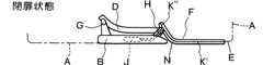
図1、図2は、従来の車体Aとスライド扉Bの基本的配置関係を示している。車体Aの出入口Cの下部近傍にはロワーレールDが固定され、車体AのクオータパネルEにはセンターレールFが固定される。スライド扉Bには、ロワーレールD及びセンターレールFにそれぞれスライド自在に係合するロワーローラーアームユニットGと、センターローラーアームユニットHとが設けられる。各ローラーアームユニットG、Hは、スライド扉Bに揺動自在に軸止される。これらのローラーアームユニットとレールとの間のスライド係合により、スライド扉Bは開扉方向及び閉扉方向に移動可能となる。1 and 2 show a basic arrangement relationship between a conventional vehicle body A and a sliding door B. FIG. A lower rail D is fixed near the lower part of the entrance / exit C of the vehicle body A, and a center rail F is fixed to a quarter panel E of the vehicle body A. The slide door B is provided with a lower roller armunit G and a center roller armunit H that are slidably engaged with the lower rail D and the center rail F, respectively. Each roller armunit G, H is sealed shaft swingably in sliding door B. By sliding engagement between these roller armunits and the rail, the slide door B can move in the door opening direction and the door closing direction.
スライド扉Bを移動させる動力スライド装置の動力ユニットJは、車体Aに設けられるときと、図示のように、スライド扉Bの内部に設けられるときとがある。後者の場合、動力ユニットJから伸びる2本のワイヤーケーブル、即ち、開扉用ケーブルK’と閉扉用ケーブルK”の先端は、図1〜3のように、センターアームユニットHのプーリーLを経由してセンターレールFの前後両端近傍にそれぞれ固定される。動力ユニットJが開扉作動すると、開扉用ケーブルK’は巻き取られ、閉扉用ケーブルK”は引き出されて、スライド扉Bは開扉方向(図1において右方)に移動し、閉扉作動すると、閉扉用ケーブルK”が巻き取られ、開扉用ケーブルK’は引き出され、スライド扉Bは閉扉方向に移動する。このとき、巻取側ケーブルが、動力ユニットJのワイヤードラムの回転により巻き取られる量と、引出側ケーブルがワイヤードラムから引き出される量とは同一となるから、動力ユニットJから伸びた2本のワイヤーケーブルの合計総長は、スライド扉Bがスライド移動しても変動しない。The power unit J of the power slide device that moves the slide door B may be provided in the vehicle body A or may be provided in the slide door B as illustrated. In the latter case, the ends of the two wire cables extending from the power unit J, that is, the opening cable K ′ and the closing cable K ″ pass through the pulley L of the center armunit H as shown in FIGS. Are fixed to the vicinity of both front and rear ends of the center rail F. When the power unit J is opened, the opening cable K ′ is wound up, the closing cable K ″ is pulled out, and the sliding door B is opened. When the door is moved in the door direction (rightward in FIG. 1) and the door is closed, the door closing cable K ″ is wound up, the door opening cable K ′ is pulled out, and the sliding door B moves in the door closing direction. The amount that the winding side cable is wound by the rotation of the wire drum of the power unit J and the amount that the drawing side cable is pulled out from the wire drum are the same. Sum total length of two wires cable, the slide door B does not fluctuate even if the sliding movement.
ところで、図3のように、支持軸Mでスライド扉Bに軸止されたセンターローラーアームユニットHは、センターレールFの前側に形成された彎曲部Nの影響で、スライド扉Bが開扉方向に移動するときは支持軸Mを中心に反時計回転方向に閉扉方向に移動するときは時計回転方向に回転する。Meanwhile, as shown in FIG. 3, the shaft sealed center roller armunit H to the sliding door B at the support shaft M is the influence of the curved portion N formed in the front of the center rail F, the sliding door B is the opening direction When moving in the counterclockwise direction around the support shaft M, it moves in the clockwise direction when moving in the door closing direction.
上記従来例では、彎曲部Nの影響によりセンターローラーアームユニットHが首振りすると、巻取側ケーブルの経路長(以下、特に言及がない限りセンターローラーアームユニットH(プーリーL)から扉Bに至るまでの経路長を言う。)は長くなり、反対に引出側ケーブルの経路長は短くなるが、巻取側ケーブルの経路長が長くなる量と引出側ケーブルの経路長が短くなる量とは一致しない。このように、経路長の増減にバランスを欠くと、スライド扉Bの円滑な移動が妨げられることになる。The above-described conventional example, when the center roller armunit H due to the influence of the flexure N is oscillating, the path length of the take-up side cable (hereinafter, leading to the door B especially mentioned is not as long as the center roller armunit H (pulley L) Is longer, and on the contrary, the path length of the lead-out side cable is shortened, but the amount of increase in the path length of the take-up side cable is equal to the amount of decrease in the path length of the lead-out side cable. do not do. As described above, if the path length is not well balanced, smooth movement of the slide door B is hindered.
これに対して、特開2001−336352号公報には、図4のように、センターローラーアームユニットHに2個のプーリーL’、L”を設け、開扉用ケーブルK’と閉扉用ケーブルK”をプーリーL’とプーリーL”との間で互いに交差させることで、センターローラーアームユニットHが彎曲部Nの影響で首振りしても、巻取側ケーブルの経路長と引出側ケーブルの経路長の合計が変動しないようにしたセンターローラーアームユニットHの構成について開示されている。On the other hand, in Japanese Patent Laid-Open No. 2001-336352, as shown in FIG. 4, the center roller armunit H is provided with two pulleys L ′ and L ″, and a door opening cable K ′ and a door closing cable K are provided. Even if the center roller armunit H swings under the influence of the bent portion N by crossing each other between the pulley L ′ and the pulley L ”, the path length of the winding side cable and the path of the drawing side cable long total discloses a configuration of the center roller armunit H was not to change the.
この構成では、例えば、スライド扉Bが開扉移動してセンターローラーアームユニットHが反時計回転方向に首振りすると、第2プーリーL”と巻取側となる開扉用ケーブルK’との接触面(巻取側巻付き角)は徐々に大きくなり、反対に第2プーリーL”と引出側となる閉扉用ケーブルK”との接触面(引出側巻付き角)は徐々に小さくなることで、各経路長は増減するが、第2プーリーL”に対する巻付け角の増減は、巻取側と引出側とで略バランスが取れるため、合計経路長の実質的な変動は防止される。
図4の構成では、図3の構成と同様に、スライド扉Bが移動するとき、巻取側ケーブルの経路長は長くなり、引出側ケーブルの経路長が短くなる。巻取側ケーブルは、本来、動力ユニットJのワイヤードラムで巻き取られた量だけ短くなって、短くなった分だけスライド扉Bを移動させるが、スライド移動中に、巻取側ケーブルの経路長が長くなると、巻取側ケーブルはワイヤードラムの巻取量とは無関係に引っ張られ、この引張力はワイヤードラムに対して回転負荷として作用することになる。このため、スライド扉Bの円滑な移動が妨げられると共に、動力ユニットJにこの分の余裕が必要となる弊害が生じる。 In the configuration of FIG. 4, similarly to the configuration of FIG. 3, when the slide door B moves, the path length of the take-up side cable becomes longer and the path length of the lead-out side cable becomes shorter. The winding side cable is originally shortened by the amount wound by the wire drum of the power unit J, and the sliding door B is moved by the shortened amount. Becomes longer, the winding-side cable is pulled regardless of the winding amount of the wire drum, and this tensile force acts as a rotational load on the wire drum. For this reason, the smooth movement of the sliding door B is hindered, and there is a problem that the power unit J needs to have a margin for this.
よって、本発明は、車体14に取付けられ彎曲部22を備えたガイドレール15と、スライド扉17に回転自在に軸止され前記ガイドレール15にスライド自在に係合するローラー16を有するローラーアームユニット10と、前記スライド扉17に設けられた動力ユニット18と、前記動力ユニット18から伸びて前記ローラーアームユニット10のケーブルプーリー手段を経由してその先端が前記ガイドレール15の一端近傍に固定されて前記動力ユニット18により巻き取られると前記スライド扉17を開扉方向に移動させる開扉用ケーブル20と、前記動力ユニット18から伸びて前記ローラーアームユニット10の前記ケーブルプーリー手段を経由してその先端が前記ガイドレール15の他端近傍に固定されて前記動力ユニット18により巻き取られると前記スライド扉17を閉扉方向に移動させる閉扉用ケーブル21とを有するものにおいて、前記ケーブルプーリー手段は、前記車体14側に近接した一個の車体側第1プーリー11と、前記スライド扉17側に近接した一個の扉側第3プーリー13と、前記車体側第1プーリー11と前記扉側第3プーリー13との間に設けられた一個以上の奇数個からなる中間第2プーリー12とを備え、前記各プーリー11、12、13は全て前記ローラーアームユニット10に軸止させ、前記開扉用ケーブル20と前記閉扉用ケーブル21とは前記各プーリー11、12、13間で互いに交差するように前記プーリー11、12、13に掛け回して前記ローラーアームユニット10が前記彎曲部22を通過するとき前記動力ユニット17により巻き取られる側のケーブルと前記プーリー11、12、13との接触面の長さは徐々に短くなり引き出される側のケーブルと前記プーリー11、12、13との接触面の長さは徐々に長くなるように構成した車両スライド扉用ローラーアームユニットとしたものである。
また、本発明は、車体14に取付けられ彎曲部22を備えたガイドレール15と、スライド扉17に回転自在に軸止され前記ガイドレール15にスライド自在に係合するローラー16を有するローラーアームユニット10と、前記スライド扉17に設けられた動力ユニット18と、前記動力ユニット18から伸びて前記ローラーアームユニット10のケーブルプーリー手段を経由してその先端が前記ガイドレール15の一端近傍に固定されて前記動力ユニット18により巻き取られると前記スライド扉17を開扉方向に移動させる開扉用ケーブル20と、前記動力ユニット18から伸びて前記ローラーアームユニット10の前記ケーブルプーリー手段を経由してその先端が前記ガイドレール15の他端近傍に固定されて前記動力ユニット18により巻き取られると前記スライド扉17を閉扉方向に移動させる閉扉用ケーブル21とを有するものにおいて、前記ケーブルプーリー手段は、前記車体14側に近接した一個の車体側第1プーリー11と、前記スライド扉17に軸止した一個の扉側第3プーリー13と、前記車体側第1プーリー11と前記扉側第3プーリー13との間に設けられた一個以上の奇数個からなる中間第2プーリー12とを備え、前記車体側第1プーリー11および前記中間第2プーリー12は前記ローラーアームユニット10に軸止させ、前記開扉用ケーブル20と前記閉扉用ケーブル21とは前記扉側第3プーリー13に隣接する一個の前記中間第2プーリー12と前記第3プーリー13との間では互いに交差させるが前記ローラーアームユニット10に軸止させた前記車体側第1プーリー11および前記中間第2プーリー12同士間では交差せないように前記プーリー11、12、13に掛け回して前記ローラーアームユニット10が前記彎曲部22を通過するとき前記動力ユニット17により巻き取られる側のケーブルと前記プーリー11、12、13との接触面の長さは徐々に短くなり引き出される側のケーブルと前記プーリー11、12、13との接触面の長さは徐々に長くなるように構成した車両スライド扉用ローラーアームユニットとしたものである。
また、本発明は、スライド扉17に取付けられ彎曲部22を備えたガイドレール15と、車体14に回転自在に軸止され前記ガイドレール15にスライド自在に係合するローラー16を有するローラーアームユニット10と、前記車体14に設けられた動力ユニット18と、前記動力ユニット18から伸びて前記ローラーアームユニット10のケーブルプーリー手段を経由してその先端が前記ガイドレール15の一端近傍に固定されて前記動力ユニット18により巻き取られると前記スライド扉17を開扉方向に移動させる開扉用ケーブル20と、前記動力ユニット18から伸びて前記ローラーアームユニット10の前記ケーブルプーリー手段を経由してその先端が前記ガイドレール15の他端近傍に固定されて前記動力ユニット18により巻き取られると前記スライド扉17を閉扉方向に移動させる閉扉用ケーブル21とを有するものにおいて、前記ケーブルプーリー手段は、一個の車体側プーリーと、一個の扉側プーリーと、前記車体側プーリーと前記扉側プーリーとの間に設けられた一個以上の奇数個からなる中間プーリーとを備え、前記各プーリーは全て前記ローラーアームユニット10に軸止させ、前記開扉用ケーブル20と前記閉扉用ケーブル21とは前記各プーリー間で互いに交差するように前記プーリーに掛け回して前記ローラーアームユニット10が前記彎曲部22を通過するとき前記動力ユニット17により巻き取られる側のケーブルと前記プーリーとの接触面の長さは徐々に短くなり引き出される側のケーブルと前記プーリーとの接触面の長さは徐々に長くなるように構成した車両スライド扉用ローラーアームユニットとしたものである。
また、本発明は、スライド扉17に取付けられ彎曲部22を備えたガイドレール15と、車体14に回転自在に軸止され前記ガイドレール15にスライド自在に係合するローラー16を有するローラーアームユニット10と、前記車体14に設けられた動力ユニット18と、前記動力ユニット18から伸びて前記ローラーアームユニット10のケーブルプーリー手段を経由してその先端が前記ガイドレール15の一端近傍に固定されて前記動力ユニット18により巻き取られると前記スライド扉17を開扉方向に移動させる開扉用ケーブル20と、前記動力ユニット18から伸びて前記ローラーアームユニット10の前記ケーブルプーリー手段を経由してその先端が前記ガイドレール15の他端近傍に固定されて前記動力ユニット18により巻き取られると前記スライド扉17を閉扉方向に移動させる閉扉用ケーブル21とを有するものにおいて、前記ケーブルプーリー手段は、前記車体に軸止した一個の車体側プーリーと、一個の扉側プーリーと、前記車体側プーリーと前記扉側プーリーとの間に設けられた一個以上の奇数個からなる中間プーリーとを備え、前記扉側プーリーおよび前記中間プーリーは前記ローラーアームユニット10に軸止させ、前記開扉用ケーブル20と前記閉扉用ケーブル21とは前記車体側プーリーに隣接する一個の中間プーリーと前記車体側プーリーとの間では互いに交差させるが前記ローラーアームユニット10に軸止させたプーリー同士間では交差せないように前記プーリーに掛け回して前記ローラーアームユニット10が前記彎曲部22を通過するとき前記動力ユニット17により巻き取られる側のケーブルと前記プーリーとの接触面の長さは徐々に短くなり引き出される側のケーブルと前記プーリーとの接触面の長さは徐々に長くなるように構成した車両スライド扉用ローラーアームユニットとしたものである。Therefore, the present invention provides a roller arm unit havinga
In addition, the present invention is a roller arm unit having a
In addition, the present invention provides a roller arm unit havinga
In addition, the present invention provides a roller arm unit having a
本発明では、ローラーアームユニット10が彎曲部22の影響で首振りしても、合計経路長に変化は起こらず、加えて、従来とは逆に巻取側のケーブルの経路長が短くなる(巻取側のケーブルとプーリーとの接触面の長さが短くなる)ようにしたから、ローラーアームユニット10の首振り運動によるワイヤードラムへの負荷増大は防止される。In the present invention, the
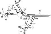
本発明の実施例を図により説明する。図5は本発明によるスライド扉用ローラーアームユニット10の概略を示しており、ローラーアームユニット10には、複数(3個以上の奇数個で、好適には3個)のプーリー11、12、13が回転のみ自在に軸止されている。ローラーアームユニット10は、所謂センターローラーアームユニットであり、ローラーアームユニット10の先端側には車体14に固定のガイドレール15にスライド自在に係合する複数のローラー16が軸止される。ローラーアームユニット10は第3ローラー13の軸芯を中心に回転自在となるようにスライド扉17に軸止され、スライド扉17の内部には動力スライド装置の動力ユニット18が設けられる。動力ユニット18はモータ動力で回転するワイヤードラム19を有し、ワイヤードラム19には開扉用ケーブル20及び閉扉用ケーブル21の基端側が巻回され、開扉用ケーブル20の先端側はプーリー11〜13を経由した後、ガイドレール15に沿って後方に伸ばしてガイドレール15の後端部近傍に固定し、閉扉用ケーブル21の先端側はプーリー11〜3を経由した後、ガイドレール15に沿って前方に伸ばしてガイドレール15の前端部近傍に固定する。An embodiment of the present invention will be described with reference to the drawings. FIG. 5 shows an outline of a
なお、ローラーアームユニット10は、スライド扉17ではなく車体14に軸止することも可能であり、この場合には、ガイドレール15はスライド扉17に固定し、動力ユニット18は車体14に取付けることになる。つまり、図5において、14をスライド扉、17を車体と見做せばよい。 The
前記開扉用ケーブル20及び閉扉用ケーブル21は、第1プーリー11と第2プーリー12との間、及び第2プーリー12と第3プーリー13との間で、それぞれ互いに交差するように配索させる。 The opening
前記ローラーアームユニット10は、図5において、ガイドレール15に形成された彎曲部22の影響で、スライド扉17が開扉方向に移動するときは反時計回転方向に、また閉扉方向に移動するときは時計回転方向に回転し、例えば、開扉スライドのときは、第3プーリー13と巻取側となる開扉用ケーブル20との接触面(巻取側巻付き角)は徐々に小さくなり、反対に第3プーリー13と引出側となる閉扉用ケーブル21との接触面(引出側巻付き角)は徐々に大きくなることで、各経路長(以下、特に言及がない限りローラーアームユニット10(第1プーリー11)から扉17に至るまでの経路長を言う。)は増減する。このように、本発明では、ローラーアームユニット10が彎曲部22の影響で首振りするとき、従来とは逆に巻取側ケーブルの経路長が短くなることに特徴がある。なお、第3プーリー13に対する巻付け角の増減は、巻取側と引出側とで略バランスが取れるため、従来と同様に合計経路長の実質的な変動は防止される。 In FIG. 5, the
図6〜9には、ローラーアームユニット10の具体的構成を示す。23は、スライド扉17(又は車体14)のパネルであり、パネル23にはヒンジブラケット24が螺子等により固定される。ヒンジブラケット24にはヒンジ軸25によりローラーアームユニット10の第1アームプレート26の基部が軸止され、第1アームプレート26の先端側にはボルト27により第2アームプレート28が固定される。第2アームプレート28の下面には、前記ローラー16を構成する複数の縦回転軸ローラー16Aが軸止される。第2アームプレート28の上面には、L型の補助プレート29が固定され、補助プレート29の縦壁にローラー16の横回転軸ローラー16Bが軸止される。 6 to 9 show a specific configuration of the
前記ローラーアームユニット10の下部にはプーリーユニット30が螺子31により固定される。プーリーユニット30は、上部ケース32と下部ケース33とを備え、その内部に前記プーリー11、12、13が回転のみ自在にプーリー軸34〜36により軸止される。プーリー11、12、13は比較的自由に配置でき、基本的には、開扉用ケーブル20及び閉扉用ケーブル21の双方が、プーリー11、12、13に対して常時接触する条件を満たせば良く、この意味で、各プーリー軸34〜36を直線上に配置する必要はない。 A
前記パネル23の内側には、ゴムシール37を介してケーブルホルダー38が取付けられ、ケーブルホルダー38にはプーリーブラケット39の基部が固定される。プーリーブラケット39の先端側は上部ケース32に固定する。プーリーブラケット39には縦の支持筒40が取付けられ、支持筒40の下部には第3プーリー13の第3プーリー軸36が回転自在に挿入され、支持筒40の上部にはヒンジ軸25の下部が回転自在に挿入される。これにより、第3プーリー軸36とヒンジ軸25とは同一軸芯上に保持される。 A
前記ヒンジブラケット24には、補強プレート41の上部を溶接等により固定し、補強プレート41の下部は螺子42等によりプーリーブラケット39に固定する。 The upper part of the reinforcing
本発明は以上の構成であり、組立に際しては、まず、ヒンジブラケット24にヒンジ軸25によりローラーアームユニット10の第1アームプレート26の基部を軸止し、プーリーユニット30に固定したプーリーブラケット39の基部側をパネル23の開口を介してパネル23の内側に差込みながら、支持筒40の上部をヒンジ軸25の下部に嵌め込み、プーリーブラケット39の基部をケーブルホルダー38に固定する。ついで、プーリーユニット30は第1アームプレート26に螺子31により止着し、ヒンジブラケット24に補強プレート41の上部を溶接等により固定し、補強プレート41の下部は螺子42等によりプーリーブラケット39に固定する。 The present invention has the above-described configuration. When assembling, first, the base of the
次に、ローラーアームユニット10の第2アームプレート28は、単独でガイドレール15にスライド自在に係合させておき、この第2アームプレート26を第1アームプレート26にボルト27により固定する。その後、開扉用ケーブル20及び閉扉用ケーブル21の各先端をガイドレール15の前後両端近傍にそれぞれ固定する。 Next, the
しかして、ローラーアームユニット10は、ガイドレール15に形成された彎曲部22を開扉方向に通過するときは反時計回転方向に首振りし、また閉扉方向に通過するときは時計回転方向に首振りするが、本発明では、ローラーアームユニット10が首振りするとき、巻き取られる側のケーブル20又は21と第3プーリー13との接触面(巻取側巻付き角)は徐々に小さくなり、反対に引き出される側のケーブル21又は20と第3プーリー13との接触面(引出側巻付き角)は徐々に大きくなるように設定されている。このため、ローラーアームユニット10が彎曲部22を通過する際に、巻き取られる側のケーブル20又は21が経路長の増大により引っ張られることが無くなり、ワイヤードラム19に余計な負荷が掛かることが防止される。また、スライド扉17がスライド移動するときのスライド抵抗は、ローラーアームユニット10が彎曲部22を通過するときが最大になるから、ローラーアームユニット10が彎曲部22を通過する際の抵抗増大を抑制することは、スライド扉17の安定したスライド移動をもたらし、また、動力ユニット18のパワーに余裕をもたらす。Thus, the rollerover the
図10に示した別の実施例では、第3プーリー13は、スライド扉17(又は車体14)に直接軸止され、ローラーアームユニット10は、第2プーリー12の第2プーリー軸35の軸芯を中心に首振りするように構成されている。また、開扉用ケーブル20及び閉扉用ケーブル21は、第1プーリー11と第2プーリー12との間では交差させずに、第2プーリー12と第3プーリー13との間のみで互いに交差させてある。この実施例では、ローラーアームユニット10が首振りした場合、巻き取られる側のケーブル20又は21と第2プーリー12との接触面(巻取側巻付き角)が徐々に小さくなり、引き出される側のケーブル21又は20と第2プーリー13との接触面(引出側巻付き角)は徐々に大きくなる。 In another embodiment shown in FIG. 10, the
10…ローラーアームユニット、11〜13…プーリー、14…車体、15…ガイドレール、16…ローラー、17…スライド扉、18…動力ユニット、19…ワイヤードラム、20…開扉用ケーブル、21…閉扉用ケーブル、22…彎曲部、23…パネル、24…ヒンジブラケット、25…ヒンジ軸、26…第1アームプレート、27…ボルト、28…第2アームプレート、29…補助プレート、30…プーリーユニット、31…螺子、32…上部ケース、33…下部ケース、34〜36…プーリー軸、37…ゴムシール、38…ケーブルホルダー、39…プーリーブラケット、40…支持筒、41…補強プレート、42…螺子。 DESCRIPTION OF
Claims (4)
Translated fromJapanesePriority Applications (2)
| Application Number | Priority Date | Filing Date | Title |
|---|---|---|---|
| JP2004186367AJP4153904B2 (en) | 2004-06-24 | 2004-06-24 | Roller arm unit for vehicle sliding door |
| US11/165,583US7533926B2 (en) | 2004-06-24 | 2005-06-24 | Roller arm unit for vehicle sliding door |
Applications Claiming Priority (1)
| Application Number | Priority Date | Filing Date | Title |
|---|---|---|---|
| JP2004186367AJP4153904B2 (en) | 2004-06-24 | 2004-06-24 | Roller arm unit for vehicle sliding door |
Publications (2)
| Publication Number | Publication Date |
|---|---|
| JP2006009350A JP2006009350A (en) | 2006-01-12 |
| JP4153904B2true JP4153904B2 (en) | 2008-09-24 |
Family
ID=35776884
Family Applications (1)
| Application Number | Title | Priority Date | Filing Date |
|---|---|---|---|
| JP2004186367AExpired - Fee RelatedJP4153904B2 (en) | 2004-06-24 | 2004-06-24 | Roller arm unit for vehicle sliding door |
Country Status (2)
| Country | Link |
|---|---|
| US (1) | US7533926B2 (en) |
| JP (1) | JP4153904B2 (en) |
Families Citing this family (13)
| Publication number | Priority date | Publication date | Assignee | Title |
|---|---|---|---|---|
| EP2048037A1 (en)* | 2006-07-31 | 2009-04-15 | The Furukawa Electric Co., Ltd. | Electricity supply device for sliding door |
| US8127497B2 (en)* | 2006-09-26 | 2012-03-06 | Strattec Power Access Llc | Apparatus and method for providing a sliding door mechanism |
| JP5125234B2 (en)* | 2007-06-05 | 2013-01-23 | アイシン精機株式会社 | Sliding door device for vehicle |
| US7856759B2 (en)* | 2008-12-18 | 2010-12-28 | Ford Global Technologies, Llc | Dual action power drive unit for a vehicle door |
| JP5633141B2 (en)* | 2009-11-27 | 2014-12-03 | アイシン精機株式会社 | Vehicle door opening and closing device |
| JP5654813B2 (en)* | 2010-09-15 | 2015-01-14 | 株式会社ミツバ | Power slide device |
| JP5654814B2 (en)* | 2010-09-15 | 2015-01-14 | 株式会社ミツバ | Power slide device |
| CN102654008A (en)* | 2010-10-29 | 2012-09-05 | 宁波信泰机械有限公司 | Sliding door transmission gear of automobile |
| US8800206B2 (en)* | 2012-08-20 | 2014-08-12 | New Visions Yezirot Aluminum, Ltd. | Motorized closure assembly |
| KR20150074806A (en)* | 2013-12-24 | 2015-07-02 | 기아자동차주식회사 | Sliding door for vehicle |
| KR101542980B1 (en)* | 2013-12-27 | 2015-08-07 | 현대자동차 주식회사 | Rear door device of vehicle |
| KR101542981B1 (en)* | 2013-12-27 | 2015-08-07 | 현대자동차 주식회사 | Front door device of vehicle |
| KR102854813B1 (en)* | 2020-05-13 | 2025-09-04 | 현대자동차주식회사 | Guide mechanism for sliding door |
Family Cites Families (3)
| Publication number | Priority date | Publication date | Assignee | Title |
|---|---|---|---|---|
| JP3855600B2 (en)* | 2000-05-29 | 2006-12-13 | アイシン精機株式会社 | Sliding door device for vehicle |
| JP3814520B2 (en)* | 2001-11-15 | 2006-08-30 | アイシン精機株式会社 | Sliding door device for vehicle |
| JP3726960B2 (en)* | 2002-06-20 | 2005-12-14 | 三井金属鉱業株式会社 | Power sliding device for vehicle sliding door |
- 2004
- 2004-06-24JPJP2004186367Apatent/JP4153904B2/ennot_activeExpired - Fee Related
- 2005
- 2005-06-24USUS11/165,583patent/US7533926B2/ennot_activeExpired - Fee Related
Also Published As
| Publication number | Publication date |
|---|---|
| US7533926B2 (en) | 2009-05-19 |
| US20060181109A1 (en) | 2006-08-17 |
| JP2006009350A (en) | 2006-01-12 |
Similar Documents
| Publication | Publication Date | Title |
|---|---|---|
| JP4153904B2 (en) | Roller arm unit for vehicle sliding door | |
| JP3855600B2 (en) | Sliding door device for vehicle | |
| US8893436B2 (en) | Invisible sliding door link structure | |
| JP5633141B2 (en) | Vehicle door opening and closing device | |
| KR101438961B1 (en) | Sliding Door | |
| JP4492550B2 (en) | Swing slide door routing structure | |
| US11585141B2 (en) | Apparatus for preventing sliding door for vehicle from swaying | |
| CN107415661A (en) | Movable body powered construction | |
| JP5079636B2 (en) | Dust input box for garbage truck | |
| JP2008094323A (en) | Door opening/closing structure for vehicle | |
| US6935071B2 (en) | Powered sliding device for vehicle slide door | |
| CN101404401A (en) | Harness protector structure for link | |
| WO2018151292A1 (en) | Opening/closing mechanism for opening/closing body | |
| JP2008067563A (en) | Constant power supply device | |
| JP4452590B2 (en) | Opening and closing device for vehicle opening and closing body | |
| JP2002144876A (en) | Door harness laying structure for sliding door | |
| JP2008266938A (en) | Sliding door driving device for vehicle | |
| JP3743279B2 (en) | Slide harness door harness wiring structure | |
| WO2015034063A1 (en) | Power-supply structure for sliding structure | |
| JP3995675B2 (en) | Roller arm unit for vehicle sliding door | |
| JP4107531B2 (en) | Vehicle sliding door | |
| JP5075604B2 (en) | Vehicle door opening and closing device | |
| JP5485026B2 (en) | Automatic folding door system | |
| JP3823734B2 (en) | Slide harness door harness wiring structure | |
| JP2005124352A (en) | Power supply structure for sliding door |
Legal Events
| Date | Code | Title | Description |
|---|---|---|---|
| A621 | Written request for application examination | Free format text:JAPANESE INTERMEDIATE CODE: A621 Effective date:20060524 | |
| A977 | Report on retrieval | Free format text:JAPANESE INTERMEDIATE CODE: A971007 Effective date:20080214 | |
| A131 | Notification of reasons for refusal | Free format text:JAPANESE INTERMEDIATE CODE: A131 Effective date:20080304 | |
| A521 | Request for written amendment filed | Free format text:JAPANESE INTERMEDIATE CODE: A523 Effective date:20080404 | |
| TRDD | Decision of grant or rejection written | ||
| A01 | Written decision to grant a patent or to grant a registration (utility model) | Free format text:JAPANESE INTERMEDIATE CODE: A01 Effective date:20080701 | |
| A01 | Written decision to grant a patent or to grant a registration (utility model) | Free format text:JAPANESE INTERMEDIATE CODE: A01 | |
| A61 | First payment of annual fees (during grant procedure) | Free format text:JAPANESE INTERMEDIATE CODE: A61 Effective date:20080704 | |
| R150 | Certificate of patent or registration of utility model | Free format text:JAPANESE INTERMEDIATE CODE: R150 Ref document number:4153904 Country of ref document:JP Free format text:JAPANESE INTERMEDIATE CODE: R150 | |
| FPAY | Renewal fee payment (event date is renewal date of database) | Free format text:PAYMENT UNTIL: 20110711 Year of fee payment:3 | |
| FPAY | Renewal fee payment (event date is renewal date of database) | Free format text:PAYMENT UNTIL: 20110711 Year of fee payment:3 | |
| S111 | Request for change of ownership or part of ownership | Free format text:JAPANESE INTERMEDIATE CODE: R313113 | |
| FPAY | Renewal fee payment (event date is renewal date of database) | Free format text:PAYMENT UNTIL: 20110711 Year of fee payment:3 | |
| R350 | Written notification of registration of transfer | Free format text:JAPANESE INTERMEDIATE CODE: R350 | |
| FPAY | Renewal fee payment (event date is renewal date of database) | Free format text:PAYMENT UNTIL: 20120711 Year of fee payment:4 | |
| FPAY | Renewal fee payment (event date is renewal date of database) | Free format text:PAYMENT UNTIL: 20130711 Year of fee payment:5 | |
| R250 | Receipt of annual fees | Free format text:JAPANESE INTERMEDIATE CODE: R250 | |
| FPAY | Renewal fee payment (event date is renewal date of database) | Free format text:PAYMENT UNTIL: 20140711 Year of fee payment:6 | |
| R250 | Receipt of annual fees | Free format text:JAPANESE INTERMEDIATE CODE: R250 | |
| R250 | Receipt of annual fees | Free format text:JAPANESE INTERMEDIATE CODE: R250 | |
| R250 | Receipt of annual fees | Free format text:JAPANESE INTERMEDIATE CODE: R250 | |
| R250 | Receipt of annual fees | Free format text:JAPANESE INTERMEDIATE CODE: R250 | |
| R250 | Receipt of annual fees | Free format text:JAPANESE INTERMEDIATE CODE: R250 | |
| R250 | Receipt of annual fees | Free format text:JAPANESE INTERMEDIATE CODE: R250 | |
| R250 | Receipt of annual fees | Free format text:JAPANESE INTERMEDIATE CODE: R250 | |
| R250 | Receipt of annual fees | Free format text:JAPANESE INTERMEDIATE CODE: R250 | |
| LAPS | Cancellation because of no payment of annual fees |