JP4153104B2 - Motorcycle frame structure - Google Patents
Motorcycle frame structureDownload PDFInfo
- Publication number
- JP4153104B2 JP4153104B2JP27235098AJP27235098AJP4153104B2JP 4153104 B2JP4153104 B2JP 4153104B2JP 27235098 AJP27235098 AJP 27235098AJP 27235098 AJP27235098 AJP 27235098AJP 4153104 B2JP4153104 B2JP 4153104B2
- Authority
- JP
- Japan
- Prior art keywords
- frame
- portions
- main
- main frame
- welded
- Prior art date
- Legal status (The legal status is an assumption and is not a legal conclusion. Google has not performed a legal analysis and makes no representation as to the accuracy of the status listed.)
- Expired - Fee Related
Links
Images


Landscapes
- Automatic Cycles, And Cycles In General (AREA)
- Motorcycle And Bicycle Frame (AREA)
Description
Translated fromJapanese【0001】
【発明の属する技術分野】
本発明は、プレス加工された金属板材を接合、一体化する構造の自動二輪車の車体フレーム構造の改良に関する。
【0002】
【従来の技術】
鋼板素材をプレス加工して形成した一対のメンバを溶接して一体化し、自動二輪車のフレームを構成する技術として、従来下記の技術が開示されている。
実開昭61−133486号公報、及び特開昭58−49582号公報に開示された技術は、プレス加工された側面視略々V字状で、断面視凹状の左右一対のメンバを、各メンバの上下端縁部に上下に突出したフランジ部を、左右に重ね合わせて突合せ、該フランジ部相互を溶接し、一体化し、フレームを得る構造である。
実公昭61−22072号公報に開示された技術は、側面視が略々T字状で、断面視凹状の左右一対のメンバを、各メンバの上下端縁部に上下に突出したフランジ部を重ね合せ、該フランジ部相互を溶接し、一体化し、フレームを得る構造である。
【0003】
以上の従来のフレーム構造は、極く小排気量のエンジンを搭載し、極く小型、軽量の自動二輪車のフレームであり、前者、即ち、実開昭61−133486号公報、特開昭58−49582号公報開示の自動二輪車は、側面視V字状のフレームの上位の前端部にヘッドパイプを、又上位の後端部にはシートを配置し、V字状の谷の部分にエンジン、伝動ケースを一体化したパワーユニットをスイング動可能に取り付ける式のフレームである。
一方、実公昭61−22072号公報開示のフレーム形状は、側面視T字状で単純形状で、上述と同様の極く小排気量、極く小型、軽量の自動二輪車に用いるフレームである。
【0004】
【発明が解決しようとする課題】
ところで、排気量がある程度大きい自動二輪車、或いは大型の自動二輪車では、フレームを複数のパイプ材を溶接等して形成するケースが多く、フレームの構成部品が極めて多いこと、パイプ材の曲げ加工が煩雑であること、溶接箇所が多いこと、フレームの構造が複雑であること等、フレームの製作上コストが高くなる傾向にあり、又フレームの重量も大きくなる。
そこで、従来のフレーム構造の簡素化、製作の容易化、軽量化、コストダウンを図るため、上記した従来技術のフレーム構造を採用して、排気量がある程度大きい、或いは排気量の大きい自動二輪車で、その略々全長にわたり略々水平方向に延びるバックボーン構造のフレームを得ようとした場合、次のような課題が生じる。
【0005】
先ず、左右のプレス加工メンバの上下に突出したフランジ部を左右に配置して突合せ、フランジ部相互を溶接するので、得られたフレームの上下にフランジ部が突出することとなる。
このため、フレーム上面の幅方向の中央部に全長にわたり突起が突出し、フレーム上面に自動二輪車の補機類を配置するに際し制約を受け、又外観上重要な構成部品である燃料タンク、シートを設置する場合において、これ等の設置に制約を受け、フレーム上に直接燃料タンクやシートを設置することが難しくなることから、これ等部品の取付スティ類やブラケット類を必要とし、フレーム構造が複雑化し、又フレーム構成部品が多くなり、この結果、溶接箇所も多く、フレーム製作上コスト的に不利である。
【0006】
本発明は、以上の課題を解決するためになされたもので、その目的とする処は、簡素な構造で高い剛性、強度を得ることが可能であり、排気量の大きい自動二輪車に適用し得る金属プレス加工素材の溶接等による接合一体化構造のフレーム、特にメインフレームを含むフレームを得ることができ、しかも、製作が容易で、構成部品が少なくてすみ、コストダウンを図ることができるとともに、軽量化にも資する自動二輪車のフレーム構造を提供することにある。
【0007】
【課題を解決するための手段】
上記課題を解決するために請求項1は、プレス加工された一対の凹状に形成された金属板材を接合して一体化した自動二輪車のフレームにおいて、一対の金属板材を、下向きに開放された断面視凹状のアッパメンバと、上向きに開放された断面視凹状の下側のロアメンバとで構成し、アッパメンバとロアメンバの上下に突合せる両側端部には、外側方に突出し、相互に上下に重なるフランジ部を備え、該フランジ部を溶接で接合し、前端部にヘッドパイプを接合し、上面が略々平坦なメインフレームを形成し、メインフレームのロアメンバには、プレス加工で形成したフレームのサブフレームを垂下するように接合し、サブフレームが2つのプレス成形部材が溶接された閉断面構造を有することを特徴とする。
【0008】
請求項1では、自動二輪車のバックボーン構造のメインフレームを、プレス加工した金属板材で、所期の剛性、強度を確保しつつ、簡易に、安価に得ることができ、メインフレームも、上面が略々平坦なので、補機類や燃料タンク、シート等の構成部品を、そのまま、或いは簡素なスティ類やブラケット類で取付、支持することができ、更にフレームは、上下のプレス加工板材を上下に接合した構造なので、軽量化が図れ、又メインフレームに接合するヘッドパイプ、エンジンハンガ、或いは取り付ける補機類や燃料タンク、シートに必要な前部の幅、後部の幅に容易に設定することが可能である。
また、車体のメインフレームを構成するメンバ以外のフレームのサブメンバをプレス加工で形成し、メインフレームメンバのロアメンバに溶接等するので、車体構成部品の構成、製作が簡易であり、自動二輪車の車体を軽量、且つ安価に製作することができる。
又サブフレームが2つのプレス成形部材が溶接された閉断面構造を有するので、サブフレームは閉断面構造体となり、高い剛性が得られ、エンジンの後部ハンガ及びスイングアームの支持構造体として必要、且つ十分の剛性、強度を確保するも可能である。
【0009】
請求項2は、請求項1記載において、前記メインフレームのアッパメンバ、又はロアメンバの一方のフランジ部の外側端部を折り曲げ、他方のフランジ部の先端部を該折り曲げ部で覆うようにしたことを特徴とする。
請求項2では、フランジ部の外側端部の折り曲げ部で、フランジ部の剛性、強度を高めることができ、剛性、強度アップの構造も簡素であり、フランジ部の加工に、先端部の曲げ加工を追加するだけで良い。
【0010】
請求項3は、請求項1記載において、前記メインフレームのアッパメンバ、ロアメンバとの間の一部には、リヤクッションユニットの取付部を構成するクロスメンバを横架するように介設したことを特徴とする。
アッパメンバと、ロアメンバとの接合構造体からなるメインフレームの、アッパメンバとロアメンバの一部間に、リヤクッションユニットを取り付けるクロスメンバを横架して介装したので、クロスメンバの取付構造が簡素であり、メインフレームのリヤクッションユニットの取付部の剛性、強度を高めることができる。
【0011】
請求項4は、請求項1記載において、前記メインフレームのアッパメンバの上面の一部には、燃料タンク及びシート取付部をプレス加工で一体に形成したことを特徴とする。
請求項4では、メインフレームの上面に、燃料タンク及びシート取付部を別個のメンバを用いることなく一体に形成することができるので、フレーム構造の簡素化、フレーム構成部品の部品点数の削減、溶接等の工数の削減、コストダウンを図ることができる。
【0012】
請求項5は、請求項1記載において、サブフレームは、平面視が凹状で、左右の側壁部を備えたメインメンバと、該メインメンバよりも深さが浅い平面視凹状で、左右の側壁部を備えたサブメンバとを備え、該サブメンバはメインメンバの前方から嵌め込み溶接されているようにしたことを特徴とする。
また、請求項6は、請求項1記載において、アッパメンバの上面の後部には、凹状のリブをプレス加工で形成したことを特徴とする。
更に請求項7は、請求項1記載において、メインフレームの前端部から前部の中間部の両側に、後下傾斜するように溶接したフロントメンバを備え、該フロントメンバは左右のメンバからなり、該メンバは対称的に外側方に膨出する膨出円形部を備え、各膨出円形部には燃料タンクの前部を取り付けるパイプ状の取付けステイを貫通させる取付孔を備えることを特徴とする。
【0015】
【発明の実施の形態】
本発明の実施の形態を添付図に基づいて以下に説明する。なお、図面は符号の向きに見るものとする。
図1は本発明にかかるフレーム構造を採用した自動二輪車の一例を示す外観側面図、図2は図1の平面図である。
図1、図2に従って自動二輪車の概略を説明すると、自動二輪車1は、後に詳細に説明するフレーム21の前端部のヘッドパイプ22を介して、フロントフォーク3により前輪2を操向自在に支持する。フレーム21の中間部下部から後方に延出したスイングアーム4を介して後輪5を支持し、スイングアーム4の後部とフレーム21との間には、後輪懸架用のリヤクッションユニット6,6を左右に介設する。
【0016】
フレーム21の前部上には燃料タンク7を設置し、フレーム21のこれの後方上には乗員跨乗用のシート8を設置し、フレーム21の燃料タンク7下方位置には、エンジン9を搭載し、エンジン9の下部後部のミッションケース10の一側方にはドライブスプロケット10aを配置し、後輪5の同側に設けたドリブンスプロケット5aとチエン10で連結し、後輪5を駆動する。
フロントフォーク3の前部の上部にはヘッドライト12を設置し、ヘッドライト12の直後で、フロントフォーク3の上端部のトップブリッジ上には、バー式のハンドル13を設置し、ハンドル13の前方にはメータユニット14を設置する。
【0017】
前記したシート7の前部の下方の左右には、サイドカウル15,15を配置してこの部分の側部を覆い、シート7の前後方向中間部〜後方の部分の側部をリヤカウル16,16で覆い、リヤカウル16,16の後部には、リヤフェンダ17を後下方に傾斜するように設置した。尚、前輪2の上半部をフロントフェンダ2aで覆う。
シート8は前後に長いタンデム式とし、シート後部の下部の左右には後席乗員把持用、及び自動二輪車のメインスタンド起立時に手掛かりとするリヤグリップ18を設置し、リヤグリップ18は、図2で明示したように平面視が略U字形である。
尚、エンジン9のシリンダ後方に配置された気化器19は、サイドカバー15の隠された後方の空間に配置される不図示のエアクリーナに接続されている。又図2において20は、自動二輪車1の後部の一側方の後方、且つ外側方に延出されたマフラーである。
【0018】
図3は本発明にかかるフレームの外観側面図である。
フレーム21は、自動二輪車の略々全長にわたる長さで、前後に長いメインフレーム30と、メインフレーム30の前端部〜前部の中間部の両側に、後下傾するように溶接したフロントメンバ40と、メインフレーム30の中間部に若干後下傾するように垂下したサブフレームを構成するミドルメンバ50と、メインフレーム30の後部〜ミドルメンバ50の下部とを繋ぐように配置したリヤメンバ70とからなる。リヤメンバ70と前方のミドルメンバ50と上方のメインフレーム30とで構成される略三角形の空間23内に、不図示のエアクリーナを配置する。
又メインフレーム30の前端部には、ヘッドパイプ22を若干前下傾するように備える。
メインフレーム30の上面は、前部〜中間部が若干下方に弯曲し、中間部と前後部とで高さに違いがあり、後部が一段高くなるように形成したが、上面は略々平坦であり、略々水平に近い状態で前後方向に延出する。
メインフレーム30の後部には、前記したシート8の後部を取付、支持するスティ81が下方に垂下するように設けられている。
【0019】
図4は図3の平面図である。
メインフレーム30は、図で示したように前部30aの幅W1が幅狭で、後部30cの幅W2が幅広に形成され、中間部30bは、この間を一体に繋ぐように、後方に向かって幅が斬増する。
【0020】
図5はフレーム21の構成メンバの分解斜視図である。
メインフレーム30は、断面形状が下向き凹状のアッパメンバ31、及び断面形状が上向き凹状のロアメンバ32とからなり、上下で対称形状をなす。各前端部には、ヘッドパイプ22の上部の後半部が嵌まる弧状の凹部31a(ロアメンバ32には表されていないが、同様に凹部を備える)を備える。これ等のアッパメンバ31、ロアメンバ32は、例えば、鋼板素材のプレス加工で成形する。
アッパメンバ31、ロアメンバ32の左右の側壁部31b,32bの対向する両端部には、各外側方に折曲して突出するフランジ部31c,32cを、夫々一体に設ける。
【0021】
アッパメンバ31の上面31dは略々平坦で、前部の前後方向中間部で、幅方向中間部には、前後に離間して電装品の取付ボス部31e,31fをプレス加工で一体成形して設ける。又上面31dの後部取付ボス部31fの直後には、断面が凹状の電装品取付スティ33を溶接し、この電装品取付スティ33を上面31d上に、その幅一杯に横断するように起立、設置する。
【0022】
又アッパメンバ31の上面31dの前後方向中間部で、幅方向中間部には、燃料タンク7、及びシート8の取付スティ34を設ける。この取付スティ34は、上面31dを上方に膨出させ、且つ後部を切り欠いて形成し、燃料タンク7の後部下面に設けた不図示の取付片を取付孔34aを介してネジ止めし、又シート8の前部の下面に設けた不図示の舌片状の取付片を切欠34bに嵌め込んで、シート前部をメインフレーム30の上面に支持する。
この取付スティ34は、アッパメンバ31の上面31dに対し、プレス加工で下方から膨出するようにして形成するので、メインフレームの構成部材とは別個の部材を必要とせず、且つアッパメンバ31を成形する工程で同時に成形することができ、部品点数の削減、別部品を溶接する必要がないことから製作が容易であり、又別部品を取り付ける必要がないことから軽量化が図れる。
このことは、上記した電装品の取付ボス部31e,31fにおいても、同様である。
【0023】
アッパメンバ31の中間後部、及びロアメンバ32の各中間後部の上下で対称部分の両側壁部31b,32bには、両側に突出したフランジ部31c,32cを含んで、夫々対称的に、アッパメンバ31側が下向き、ロアメンバ32側が上向きの弧状の凹部31g,32gからなる凹状のリブをプレス成形で一体に設ける。
アッパメンバ31、ロアメンバ32を上下で重ね合せ、フランジ部31c,32c相互を突合せて重ね合わせ、溶接する際、凹部31g,32gは円形となり、この間に、両端部でリヤクッションユニット6の上端部を取付、支持する軸状のクロスメンバ35を介在させて溶接し、メインフレーム30と一体化する。
このリヤクッションユニットの取付、支持用のクロスメンバ35の横架するような介装で、メインフレーム30のこの部分の剛性、強度を高められる。
【0024】
この際、正面視凹状のリヤカウル取付スティ36を上面31d上に配置し、取付スティ36の左右の側壁36aの下端部をクロスメンバ35の両端寄り部上半部に溶接し、又前後の突出片36b,36bをアッパメンバ31の上面31dのこの部分に溶接する。
尚、アッパメンバ31のこの部分の上面には、上方へ膨出する取付ベースを一体にプレス加工で形成しておき、この部分の上面に前後の突出片36b,36bを溶接する。
【0025】
アッパメンバ31の上面31dの後部には、前後方向に長さを有する凹状のリブ37を複数個プレス加工で形成しておき、剛性を高めた。又上面31dの後部には、その前部に左右2個、後部に1個のリヤグリップ取付孔39…(…は複数を表す。以下同じ)を備える。
一方、ロアメンバ32の中間部の側部には、エンジン補機類の取付スティ38を前後に設けた取付片38a,38aで溶接する。
【0026】
フロントメンバ40は、図3に示したように、ヘッドチューブ22後半部、メインフレーム30の前半部の前端部、及び上縁部を繋ぐものである。
フロントメンバ40は、所謂ダウンチューブの上半部に相当する構造で、鋼板素材をプレス加工した得た側面視略「く」字形の左右のメンバ41,41からなる。
左右の各板状部41aの上下を内方に折曲し、各板状部の全体の断面が凹状である。各板状部41aの各下壁片41bには、内方への凸片41cを夫々備え、各板状部41aの上縁部には、この面よりも内方にZ字形に折曲して突出した上壁片41fを夫々備える。
又各板状部41aの先部には、対称的に外側方へ膨出円形部42を夫々備え、各膨出円形部42には、燃料タンク7の前部を取り付けるパイプ状の取付スティ43を貫通する取付孔43aを夫々備える。
【0027】
又各板状部41aの中間部には、略々三角形の軽量化用の窓44を夫々備え、窓44の周縁部には内方に折曲した縁部44aを設け、剛性を高めた。
各板状部41aには、後下傾する下部延出部41dを夫々備え、この部分の断面形状も、左右で対称的な凹状とし、上述の下壁片41bはそのままこの部分の下方まで延長する。
板状部41aの側面視略「く」字形の後縁部には、各内方、且つ後方に折曲したZ字形の後壁片41eを夫々備える。
各下部延出部41dの下部には、上下に離間して取付孔45,45を夫々備え、下部延出部41d間にパイプ材からなるクロスメンバ46,46を通す。
【0028】
ミドルメンバ50は、図3に示したように、メインフレーム30の中間部から下方に垂下するように設けられるものである。
メインメンバ51、及びサブメンバ61からなり、これ等は、鋼板素材のプレス加工で得る。
メインメンバ51は、平面視が凹状で後方への深さが大きく、上下に長さが長く、左右の側壁部51b,51b、後壁部51aを備え、後壁部51aの上部を切り欠いて二股部51c,51cを備える。二股部51c,51cは、溶接面積を稼ぐように若干前後方向に長く形成されており、側壁部51b,51bの下部51d,51dは、上下にある程度の高さを有するように、略逆L字形に前方に膨出する。
【0029】
メインメンバ51の各側壁部51bの各下部51dの上方部には、凹状断面形状に沿って、断面視凹状の補強用ガセット52を内張りするように溶接して一体化する。この部分の両側部に、前記したスイングアーム4の前端部のピボットを、回動自在に支持する支持管54を、貫通して取り付ける取付孔53を形成する。
又メインメンバ51の各側壁部51bの各下部51dには、前部の上部にエンジン9の取付用の取付孔55を左右対称的に設け、各下部51dの後部には、スタンド取付用のクロスメンバ57を取り付ける取付孔56を夫々設ける。
又各側壁部51bの前記した取付孔55の上方の部分を夫々前方に突出させ、この各突出部51eには、対称的にエンジン9の取付用の取付孔58を設ける。
【0030】
サブメンバ61は、高さ方向の長さにおいて、前記したメインメンバ51の取付孔54の上方から二股部51c間の長さを有し、メインメンバ51の深さに対し、浅い断面凹状をなす。
後壁部61aの両側部から前方に折曲した側壁部61b,61bは突出量が小さく、上部61cは前方に屈曲して曲り、天井部を構成し、前記したロアメンバ32の底面32dの下面に突き当てる。又後壁部61aの下端部の幅方向中央部には、逆凹状の欠部61dを備える。
以上のサブメンバ61は、メインメンバ51の前方から嵌め込み、溶接する。
【0031】
70はリヤメンバで、図3で示すようにメインフレーム30の後部とミドルメンバー50の下部とを繋ぐものである。
リヤメンバ70は、メインメンバ71とサブメンバ74とで構成し、これ等は鋼板素材のプレス加工で得る。
メインメンバ71は側面視「弓」形をなし、断面形状は深さが大きい凹状で、後壁部71a、左右の側壁部71bからなり、各側壁部71bの各中間部には、左右のサイドカウル15の取付ボス部72を一体に設け、この部分に取付孔72aを備え、又これの下方にサイドカウル取付孔72bを備える。
【0032】
メインメンバ71の前方に突出した各側壁部71bの各下部71cには、左右で対称的な前方に開く凹状の二股部73を夫々設ける。この二股部73は、ミドルメンバ50の、前記した支持管54の両側突出部を挟むようにしてミドルメンバ50のメインメンバ51のこの部分の側壁部51bに溶接する。
サブメンバ74は、後壁部74a、及びこれの両側部から前方に折曲した左右の側壁部74bを有し、断面形状が凹状である。凹状の深さが、メインメンバ71よりも小さく、且つ図3に示すように、二股部73の上方からサイドカウル15の取付ボス部72の間の長さを有する。
サブメンバ74を、メインメンバ71の二股部73の上方からサイドカウル15の取付ボス部72の間の側壁部71b間に嵌め込み、側壁部71b、74bを溶接し、双方を一体化する。これにより、リヤメンバ70のこの部分は閉断面構造となり、剛性、強度を高めた。
【0033】
次に、図6〜図9でメインフレーム30とフロントメンバ40、ミドルメンバ50、及びリヤメンバ70の接合構造を説明する。
図6は図3の6−6線拡大断面図である。
アッパメンバ31とロアメンバ32とは、対向するフランジ部31c,32cを上下に重ね合わせ、例えばスポット溶接等で所定の部位を溶接し、一体的に接合し、閉断面構造の中空なメインフレーム30を形成する。溶接部をaで示した。
前記した左右のフロントメンバ40は、左右のメンバ41,41の板状部41a,41a上縁部の上壁片41f,41fを、上記したメインフレーム30のロアメンバ32の左右の側壁部32b,32bに外側から当て、スポット溶接等で接合する。
【0034】
前記した膨出円形部42,42に設けた取付孔42a,42a間に、パイプ状取付スティ43を貫通し、このスティ43と各取付孔42a,42a周辺部とをミグ溶接等で接合し、取付スティ43を一体的に架設する。溶接箇所をbで示した。
板状部41a,41aの前端部は、ヘッドパイプ22の外周部にミグ溶接等で接合する。又板状部41a,41aの下壁部41b,41bの端部相互を突合せ、これの下面にガセット47を当てがい、このガセット47と下壁部41b,41bの外端部とをミグ溶接等で接合し、溶接部をcで示した。ガセット47の前端部は、ヘッドパイプ22の下部後半部周にミグ溶接等で接合する。
【0035】
ところで、アッパメンバ31の両側に突出したフランジ部31c,31cであるが、ロアメンバ32のフランジ部32c,32cよりも外側方への突出量を大きくし、その各先端部を下方に折曲し、この部分の断面を略逆L字形の折曲部31hとする。実施例では、メインフレーム30のアッパメンバ31の燃料タンク下方のフランジ部が下方に折曲している。
これにより、下部のロアメンバ32のフランジ部32c,32cの外端部は隠され、且つ、折曲部31hにより剛性が高くなり、アッパメンバ31、従ってこれと一体的に接合するロアメンバ32を含むメインフレーム30全体の剛性、強度を高めることができる。
【0036】
図7は図3の7−7線拡大断面図である。
前記したようにアッパメンバ31とロアメンバ32とはフランジ部31c,32cで溶接されており、ロアメンバ32の側壁部32bの一方に、前述のエンジン補機類の取付スティ38を、スポット溶接等で接合する。溶接箇所をdで示した。
取付スティ38は前後の取付片38aを含んで断面形状が略々Z字形をなし、上部の取付片38aをロアメンバ32の側壁部32bの一方に溶接し、ロアメンバ32の下方に垂下した本体部38bには、補機類取付用のウエルドナット38cを備える。
【0037】
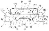
図8は図3の8−8線拡大断面図である。
この部分はリヤクッションユニットの支持部材である軸状のクロスメンバ35の取付部である。メインフレーム30のこの部分の幅は、前述したように前部に対して幅広であり、アッパメンバ31、ロアメンバ32のフランジ部のこの部分を対称的に弧状の凹部31g,32gとし、凹部31g,32g間でクロスメンバ35の両端部を挟み込み、端部周縁とクロスメンバ35との間をミグ溶接等し、溶接箇所をeで示した。
これにより、アッパメンバ31とロアメンバ32のこの部分間に、クロスメンバ35が横架するように架設されて一体的に介在され、メインフレーム30のこの部分の剛性、強度を高めることができる。
クロスメンバ35の両端部35a,35aは小径で、この部分に左右のリヤクッションユニット6,6の上端の取付ボス部6aを各取付、支持する。
【0038】
ロアメンバ31の下側には、この部分から後方にかけて、前記したリヤメンバ70のメインメンバ71後部が接合されておいる。
具体的は、メインメンバ71の後部の後壁部71aがロアメンバ31の下面31dの下方に若干隙間をもって位置し、メインメンバ71の左右の側壁部71b,71bがロアメンバ32の側壁部32b,32bの外側から重なり、側壁部71b,32b相互をスポット溶接等で接合し、リヤメンバ70のメインメンバ71の後部をメインフレーム30に接合、一体化した。
溶接箇所をfで示した。
【0039】
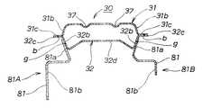
図9は図3の9−9線拡大断面図である。
メインフレーム30のアッパメンバ31のこの部分の上面31dには、前記したように左右2個の凹状のリブ37,37が前後方向に形成されておいる。
ロアメンバ32の後部の左右の側壁部32b,32bの外側部には、前記したシート取付スティ81,81が溶接されており、取付スティ81,81は左右分割構造で、鋼板素材のプレス加工で得る。
このスティ81,81は断面形状が略々Z字形類似の形状で、左右の単体81A,81Bで上下方向の長さが異なる。このスティ81,81は、上部81a,81aをロアメンバ32の左右の側壁部32b,32bの後部外側に配置し、スポット溶接等で接合し、溶接箇所をgで示した。
【0040】
図10は図3の矢視10方向から見た拡大図である。
ガセット47の正面視の形状は図10に示す通りで、フロントメンバ40の左右のメンバ41,41に設けた前記膨出円形部42,42の取付孔42a,42aに前記した燃料タンク前部の取付スティ43を左右に貫通させ、接合部をミグ溶接等で接合し、接合箇所をbで示し、スティ43の両端部43a,43aはフロントメンバ40の左右に突出する。又ガセット47の後端部部の溶接箇所は、前記したようにcである。
【0041】
左右のメンバ41,41の各下壁片41b,41bは、その下半部の対向する端部相互を突合せ、突き合せ部をミグ溶接等で接合する。溶接箇所をhで示した。
この部分は、前方に前輪2が位置し、前輪2のクッション動に起因する上下動に際し、前方への溶接による張り出し部が生じないように配慮し、前輪のクッションストロークを確保するように構成した。
又各下壁片41b,41bの上部に設けた凸片41c,41cは、前後に重ね合せ、スポット溶接等で接合し、溶接箇所をiで示した。この手法においても、溶接部分は前方に突出することが無く、上記と同様に前輪のクッションストロークを確保するように構成した。
【0042】
図11は図3の11−11線拡大断面図である。
この部分は、フロントメンバ40の下部を示しており、フロントメンバ40の前側となる左右のメンバ41,41の各下壁片41b,41bは、実際には図のようにこの部分を前後に重ね合わせ、重ね合わせた外側端縁部を溶接hする。
後部となる後壁片41e,41e相互は、フランジ状なので左右に重ね合せ、スポット溶接等で接合し、接合箇所をkで示した。
又この部分には、取付孔を介して、前記した上下2本のパイプ状のクロスメンバ46を左右に貫通し、取付孔外周辺部とクロスメンバ46とをミグ溶接等で接合し、接合箇所をjで示した。
【0043】
クロスメンバ46,46は、図3に鎖線で示したエンジン前部ハンガー82の前部をボルト83で結合し、このエンジンハンガー82の後部をエンジン9のクランクケースの前部にボルト結合し、エンジン9をフロントメンバ40に取付、支持する。
この際、フロントメンバ40は、左右のプレス加工板材の断面形状凹状の溶接、接合構造体であり、全体として閉断面構造なので、剛性が高く、重量物であるエンジン前部の支持を強固、確実に行うことができる。又左右のメンバ41,41を突合せて溶接し、クロスメンバ46,46を通して溶接する構造なので、構造が簡素で、製作も容易である。
【0044】
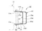
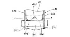
図12は図3の12−12線拡大断面図である。
ミドルメンバ50のメインメンバ51は、後壁部51a、左右に側壁部51b,51bを備え、前記したように鋼板素材のプレス加工で形成し、図のように奥行が深い。これの内側にサブメンバ61を配置し、サブメンバ61は同様に後壁部61a、左右の側壁部61b,61bを備えて同様に鋼板素材のプレス加工で形成し、奥行は浅い。
メインメンバ51の内側にサブメンバ61を嵌め込み、サブメンバ61の後壁部61aとメインメンバ51aとの間に、前後方向に空間を設け、左右(内外)に重なった側壁部61b,51b相互をスポット溶接等で接合し、溶接箇所をmで示した。
【0045】
ミドルメンバ50は、上記により閉断面構造体となり、しかも凹状構造物を嵌め込んで左右の部分を溶接したので、高い剛性が得られ、エンジン9の後部ハンガー、及びスイングアーム4の支持構造体として必要、且つ十分の剛性、強度を確保することができる。
以上で形成したミドルメンバ50のメインメンバ51の側壁部51b,51bに形成した前記の突出部51e間に、エンジン9の後部のミッションケース10の上部10bを挟み込み、取付孔58,58にボルト84を通し、ミッションケース10のこの部分10bを取付、支持する。
【0046】
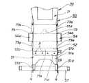
図13は図3の矢視13方向から見た拡大図である。
ミドルメンバ50のメインメンバ51の支持管54の取付部の後面からリヤメンバ70のメインメンバ71の左右の二股部73を、支持管54を二股部で挟むように差込む。左右の二股部73の上下の部分73a,73aを上述のメインメンバ51のこの部分の側壁部51b,51bに重ね合せ、スポット溶接等で溶接し、溶接箇所を図3のnで示した。
支持管54の両端部54a,54aは、側壁部51d,51dの二股部73,73の部分から外側方に突出し、スイングアーム4の前端部を回動可能に支持する。
【0047】
又支持管54を設置した部分のメインメンバ51の後壁部51a、左右の側壁部51b,51bには、重なり合うように断面凹状の補強用ガセット52を当てがって溶接し、スイングアーム支持部分を補強した。
リヤメンバ70のメインメンバ71の後壁部71a下端部には延出片71dを設け、これをスポット溶接等でメインメンバ51の後壁部51a下部に接合し、溶接箇所をpで示した。
又メインメンバ51の下部51dのには、前記したスタンド取付用のクロスメンバ57が取付孔56を介して左右に貫通するように設置され、下部51dとクロスメンバ57とはミグ溶接等で接合し、溶接箇所をqで示した。
これ等の支持管54、スタンド取付用クロスメンバ57は、何れもメインメンバの下方部、下部間に横架されており、サブメンバ61がこの部分には配置されていないが、これ等の部材が補強梁としても機能し、この部分の剛性、強度を高める。
【0048】
図14は図3の矢視14方向から見た拡大図である。
ミドルメンバ50のサブメンバ61の凹状の切欠部61dの左右の下端部は、支持管54の上面に突き当て、ミグ溶接等で接合し、溶接箇所をrで示した。
【0049】
図15は、本発明にかかる自動二輪車のフレーム製造方法を工程順に示した説明図である。
(a)はロアメンバとサブメンバの組付手前の図で、サブメンバとして図ではミドルメンバ70のメインメンバ71とロアメンバ32との溶接を示した。
メインメンバ71の上部に設けた二股部51c,51c間に、ロアメンバ32の下方に下面32d、左右の側壁部32b,32bからなる凹状となった部分を嵌め込む。
【0050】
(b)は嵌め込んだ状態、及び溶接工程を示し、二股部51c,51cの内側に左右の側壁部32b,32bが左右に重なる。一方の二股部51c、側壁部32bの各内外側からスポット溶接の電極部G,Gを押し当て、加圧し、通電してこの部分を溶接する。溶接箇所をsで示した。
図では右側の溶接を示したが、左側も同様に溶接する。これにより、ロアメンバ32の下方に、垂下するようにサブメンバ71を溶接し、接合、一体化する。
左右を溶接した状態は(c)に示した通りである。
【0051】
(c)はロアメンバ32にサブメンバであるミドルメンバのメインメンバ71を垂下するように溶接した状態で、アッパメンバ31を用意する。アッパメンバ31を矢印のように上からロアメンバ32に重ね合わせる。
(d)はアッパメンバ31をロアメンバ32上に重ね合せた状態を示し、ロアメンバ32のフランジ部32c,32c上にアッパメンバ31のフランジ部31c,31cが重なる。
爾後、縦向きに配置したスポット溶接の電極部G,Gを、フランジ部31c,32cを挟み込むようにして加圧し、通電して溶接する。溶接は左右のフランジ部に対して行う。溶接箇所をaで示した。
【0052】
以上により、(e)に示すように、サブメンバ51を予めロアメンバ32に垂下するように溶接し、爾後上からアッパメンバ31をロアメンバ32上に重ね合せ、フランジ部31c,32c相互をスポット溶接等し、下方にサブメンバ51を垂下するように接合したメインフレーム30を得る。
得られたメインフレーム30を(e)で示した。
尚、アッパメンバ31のフランジ部31c,31cの各先端部に折曲部31hを夫々設け、剛性アップとロアメンバ32のフランジ部32c端部を隠蔽した。
【0053】
本発明のフレーム製造方法においては、アッパメンバ、ロアメンバを、これ等の両端部に設けたフランジ部を上下に重ねて溶接し、閉断面構造体のメインフレームを製作するに際し、ロアメンバに予め下方に吊り下げ、垂下するサブメンバを溶接しておくので、軽量で取り扱い易いロアメンバと、同様に軽量で取り扱い易いサブメンバとの溶接が、組付、治具等の関係で容易である。
ロアメンバにサブメンバを溶接した後、アッパメンバをロアメンバ上に重ね、この際、アッパメンバ自体は、ロアメンバと一体化されていないので軽量であり、取り扱い易く、ロアメンバへのセットも容易であり、溶接もフランジ部のみで良く、この点においてもフレーム製作が容易である。
従って、フレームを簡易な手法で製作ができる。これにより、自動二輪車のフレームのコストダウンにも資することができる。又下位のロアメンバにサブメンバを、謂わば吊り下げるように予め溶接しておくので、ロアメンバとサブメンバとの溶接、配置の自由度が高くなる。
【0054】
図16は、メインフレームに物入れを設けた状態を示す要部の縦断側面図である。
メインフレーム30は、凹状断面の上下のアッパメンバ31、ロアメンバ32のフランジ部31c,32cを介した接合構造体であり、後部は前記したように幅広である。従って、後部には、上下方向にある程度の高さをもった空間90を得ることができる。
そこで、この空間90内を物入れ、例えば、薄手の物品である工具入れ等として利用することができる。アッパメンバ31の上面31dの後部に棚部付きの開口部91を設け、この部分を端部のヒンジ93で開閉自在としたリッド92で覆い、物入れ部分として利用した。
【0055】
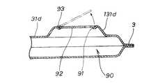
図17は、物入れの他の実施例を示す要部の縦断面図である。
前記したようにアッパメンバ31は、プレス加工で成形するので、アッパメンバ31の後部の一部に上方への膨出部131dを形成する。これにより、空間90の高さは大きくなり、膨出部131dの上面に前記と同様に棚部付きの開口部91を設け、この部分を端部のヒンジ93で開閉自在としたリッド92で覆い、物入れ部分として利用した。
この実施例によれば、厚手の高さがある物品の物入れとして利用することができる。
【0056】
以上、実施例を詳述したが、溶接手法は前記したスポット溶接、ミグ溶接に限られることはなく、抵抗溶接としてはシーム溶接、レーザ溶接等任意の溶接手法を用いてフレームを接合することができ、実施例の溶接手法に限られるものではない。
又フレーム構成部材を、鋼板素材のプレス加工として説明したが、アルミニウムの板材をプレス加工して構成部材を形成しても良く、構成部材の素材は、溶接可能であり、剛性が得られることを条件として、使用可能な金属板材のプレス加工素材を用いることができる。
【0057】
【発明の効果】
本発明は上記構成により次の効果を発揮する。
請求項1は、プレス加工された一対の凹状に形成された金属板材を接合して一体化した自動二輪車のフレームにおいて、一対の金属板材を、下向きに開放された断面視凹状のアッパメンバと、上向きに開放された断面視凹状の下側のロアメンバとで構成し、アッパメンバとロアメンバの上下に突合せる両側端部には、外側方に突出し、相互に上下に重なるフランジ部を備え、該フランジ部を溶接で接合し、前端部にヘッドパイプを接合し、上面が略々平坦なメインフレームを形成し、メインフレームのロアメンバには、プレス加工で形成したフレームのサブフレームを垂下するように接合し、サブフレームが2つのプレス成形部材が溶接された閉断面構造を有するようにしたので、先ず、バックボーン構造のメインフレームを、プレス加工した金属板材で、軽量化を図りつつ、必要とする剛性、強度を確保しつつ、簡易に、安価に得ることができる。
【0058】
特に本発明では、バックボーン形式のフレームをプレス加工のアッパメンバ、ロアメンバとの上下のフランジ部による接合一体化構造体なので、アルミニウム材の引き抜き等による閉断面パイプ構造体と異なり、自動二輪車の長さ方向の対して、車幅方向の幅を任意に設定して形成することができ、必要とするメインフレームを製作容易に、安価に得ることができる。
又メインフレームは、上面が略々平坦なので、補機類や燃料タンク、シート等の構成部品の取付部分を直接アッパメンバに形成することができ、補機類や部品取付部分を別個の部材や、これの溶接等を必要とすることなく設置することができ、この点からもメインフレームの構造、製作の簡易化、部品点数の削減、軽量化、コストダウンを図ることができる。
又メインフレームが平坦なので、補機類や部品の取付、支持部材は、簡素なスティ類やブラケット類で足り、これのアッパメンバ、ロアメンバへの取付、支持構造も簡素なもので足りる。
【0059】
又メインフレームは、上下のプレス加工板材を上下に接合した構造なので、メインフレームに接合するヘッドパイプ、エンジンハンガ、或いは取り付ける補機類や燃料タンク、シートに必要な前部の幅、後部の幅と、夫々の部分の幅を異ならせることが可能であり、メインフレームに取り付けるこれ等のフレーム部材の構造の簡素化、溶接等の容易化が図れ、前後で幅を異ならせたメインフレームを容易に得ることができ、前後で幅が異なる部分を有するフレームを容易に得ることができ、フレーム全体としての構造も簡素であり、製作の容易化、コストダウンを図ることができ、且つ、メインフレームは中空閉断面構造体となり、しかも、溶接等するフランジ部が左右に張り出してこの部分で溶接等して接合一体化する構造なので、排気量が大きい自動二輪車のメインフレームとして、高い剛性、強度を確保した自動二輪車のメインフレームを得ることができる。
また、車体のメインフレームを構成するメンバ以外のフレームのサブメンバをプレス加工で形成し、メインフレームメンバのロアメンバに溶接等をすることにより、車体構成部品の構成、フレーム構造の簡素化が図れる。
更に、メインフレーム、サブフレームともに、プレス加工した板材を溶接等で接合、一体化する構造なので、フレームの製作が簡易であり、高剛性、高強度を有する自動二輪車の車体を、軽量、且つ安価に製作することができる。
又サブフレームが2つのプレス成形部材が溶接された閉断面構造を有するので、サブフレームは閉断面構造体となり、高い剛性が得られ、エンジンの後部ハンガ及びスイングアームの支持構造体として必要、且つ十分の剛性、強度を確保するも可能である。
【0060】
請求項2は、請求項1において、前記メインフレームのアッパメンバ、又はロアメンバの一方のフランジ部の外側端部を折り曲げ、他方のフランジ部の先端部を該折り曲げ部で覆うようにしたので、請求項1の効果に加えるに、アッパメンバ、ロアメンバの一方のフランジ部の外側端部は、他方の外側端部の折り曲げ部で隠され、フレームの一部が露出する可能性のあるメインフレームの外観性が向上し、又自動二輪車全体の組立に際し、メインフレームのエッジ部が隠れるので、組立性の点においても好ましい。
特に本発明では、折り曲げ部でフランジ部の剛性、強度を一層高めることができ、剛性、強度アップの構造も、フランジ部の外側端部に折り曲げ部を設けるという簡素な手法、構成で実現することができ、上記効果を、フランジ部の加工に際し、先端部の曲げ加工を追加するだけ実現することができる。
【0061】
請求項3は、請求項1において、メインフレームのアッパメンバ、ロアメンバとの間の一部には、リヤクッションユニットの取付部を構成するクロスメンバを横架するように介設したので、自動二輪車の略々全長にわたる長さのアッパメンバと、ロアメンバとの接合構造体からなるメインフレームの、アッパメンバとロアメンバの一部間に、リヤクッションユニットを取り付けるクロスメンバを横架して介装することとなり、請求項1の効果に加えるに、メインフレームの長さを自動二輪車の略々全長にわたるような長さに形成しながら、メインフレームの剛性、強度をリヤクッションユニットの取付用クロスメンバを用いつつ高めることができ、余分な剛性、強度向上のための部材を必要とすることなく、メインフレームの剛性、強度を高めることができる。
又クロスメンバの取付構造がアッパメンバ、ロアメンバ間に挟み込んで溶接等すれば良く、リヤクッションユニットの取付部材の取付構造が簡素であり、取り付けもアッパメンバ、ロアメンバの溶接等と同時に行え、製作上も有利であり、更にアッパメンバ、ロアメンバと溶接等で一体化することで、メインフレームのリヤクッションユニットの取付部の剛性、強度を高めることができる。
【0062】
請求項4は、請求項1において、前記メインフレームのアッパメンバの上面の一部には、燃料タンク及びシート取付部をプレス加工で一体に形成したので、請求項1の効果に加えるに、メインフレームの上面に、燃料タンク及びシート取付部をメインフレームとは別個の部材を用いることなく形成することができる。
従って、メインフレームの構造の簡素化、メインフレームの構成部品の部品点数の削減、溶接等の工数の削減を図ることができ、又部品が少なくなることから、トータルとして自動二輪車のフレームの軽量化、コストダウンを図ることができる。
【0063】
請求項5は、請求項1において、サブフレームは、平面視が凹状で、左右の側壁部を備えたメインメンバと、該メインメンバよりも深さが浅い平面視凹状で、左右の側壁部を備えたサブメンバとを備え、該サブメンバはメインメンバの前方から嵌め込み溶接されているようにしたので、請求項1の効果に加えるに、サブメンバは閉断面構造体となり、しかも凹状構造物を嵌め込んで左右の部分を溶接したので、高い剛性が得られ、エンジンの後部ハンガ及びスイングアーム4の支持構造体として必要、且つ十分の剛性、強度を確保することができる。
また、請求項6は、請求項1において、アッパメンバの上面の後部には、凹状のリブをプレス加工で形成し、請求項7は、請求項1において、メインフレームの前端部から前部の中間部の両側に、後下傾斜するように溶接したフロントメンバを備え、該フロントメンバは左右のメンバからなり、該メンバは対称的に外側方に膨出する膨出円形部を備え、各膨出円形部には燃料タンクの前部を取り付けるパイプ状の取付けステイを貫通させる取付孔を備えるようにした。
【図面の簡単な説明】
【図1】本発明にかかるフレーム構造を採用した自動二輪車の一例を示す外観側面図
【図2】図1の平面図
【図3】本発明にかかるフレームの外観側面図
【図4】図3の平面図
【図5】フレーム構成メンバの分解斜視図
【図6】図3の6−6線拡大断面図
【図7】図3の7−7線拡大断面図
【図8】図3の8−8線拡大断面図
【図9】図3の9−9線拡大断面図
【図10】図3の矢視10方向から見た拡大図
【図11】図3の11−11線拡大断面図
【図12】図3の12−12線拡大断面図
【図13】図3の矢視13方向から見た図
【図14】図3の矢視14方向から見た図
【図15】(a)〜(e)はフレームの製造工程を示す説明図で、(a)はロアメンバとサブメンバの組付手前の図、(b)はロアメンバとサブメンバを組み付け、溶接する図、(c)はアッパメンバの組付手前の図、(d)はアッパメンバ、ロアメンバを溶接する図、(e)は溶接後の図
【図16】メインフレームに物入れを設けた状態を示す要部の縦断側面図
【図17】メインフレームに物入れを設けた状態の他の実施例を示す要部の縦断側面図
【符号の説明】
1…自動二輪車、 30…メインフレーム、 22…ヘッドパイプ、 31…アッパメンバ、 32…ロアメンバ、 31b,32b…フランジ部、 31c…フランジ部外側端部の折曲部、 34…燃料タンク、シートの取付部、 35…リヤクッションユニット取付用のクロスメンバ、 40、50、70…サブメンバ。[0001]
BACKGROUND OF THE INVENTION
The present invention relates to a body frame structure of a motorcycle having a structure in which pressed metal sheets are joined and integrated.Regarding improvements.
[0002]
[Prior art]
Conventionally, the following techniques have been disclosed as techniques for forming a frame of a motorcycle by welding and integrating a pair of members formed by pressing a steel plate material.
The techniques disclosed in Japanese Utility Model Laid-Open No. 61-133486 and Japanese Patent Laid-Open No. 58-49582 are formed by pressing a pair of left and right members that are substantially V-shaped in a side view and are concave in a sectional view. In this structure, the upper and lower edges of the upper and lower edges of the flanges are vertically overlapped and butted together and welded together to obtain a frame.
In the technique disclosed in Japanese Utility Model Publication No. 61-22072, a pair of left and right members that are substantially T-shaped in a side view and concave in a cross-sectional view are overlapped, and flanges that protrude vertically on the upper and lower edges of each member are overlapped. In addition, the flange portions are welded and integrated to obtain a frame.
[0003]
The conventional frame structure described above is an extremely small and lightweight motorcycle frame equipped with a very small displacement engine. The former, namely, Japanese Utility Model Laid-Open No. 61-133486, Japanese Patent Laid-Open No. 58- The motorcycle disclosed in Japanese Patent No. 49582 has a head pipe at the upper front end of the V-shaped frame in side view and a seat at the upper rear end, and the engine and transmission in the V-shaped valley portion. It is a frame of the type which attaches the power unit which integrated the case so that a swing movement is possible.
On the other hand, the frame shape disclosed in Japanese Utility Model Publication No. 61-22072 is a frame used for a motorcycle having a T-shape in a side view and a simple shape, and the same extremely small displacement, extremely small size, and light weight as described above.
[0004]
[Problems to be solved by the invention]
By the way, in a motorcycle having a large displacement or a large-sized motorcycle, there are many cases in which a frame is formed by welding a plurality of pipe materials, etc., and there are very many components of the frame, and bending of the pipe material is complicated. In other words, the number of welding locations and the structure of the frame are complex, which tends to increase the cost of manufacturing the frame, and also increases the weight of the frame.
Therefore, in order to simplify the conventional frame structure, make it easier to manufacture, reduce the weight, and reduce the cost, the above-described conventional frame structure is adopted to provide a motorcycle with a large displacement or a large displacement. When attempting to obtain a frame having a backbone structure extending substantially in the horizontal direction over its substantially entire length, the following problems arise.
[0005]
First, since the flange portions projecting up and down of the left and right press-work members are arranged on the left and right sides, and the flange portions are welded to each other, the flange portions project from the top and bottom of the obtained frame.
For this reason, a protrusion protrudes over the entire length in the center of the frame upper surface in the width direction, and there are restrictions when placing motorcycle accessories on the upper surface of the frame, and fuel tanks and seats, which are important components in appearance, are installed. In this case, it is difficult to install fuel tanks and seats directly on the frame due to restrictions on the installation of these components, which necessitates mounting brackets and brackets for these components, which complicates the frame structure. In addition, the number of frame components increases, and as a result, there are many welding points, which is disadvantageous in terms of manufacturing the frame.
[0006]
The present invention has been made to solve the above-described problems, and the object of the present invention is to obtain a high rigidity and strength with a simple structure, and can be applied to a motorcycle having a large displacement. It is possible to obtain a frame with a joint-integrated structure by welding of metal stamping materials, particularly a frame including a main frame, and it is easy to manufacture, requires fewer components, and can reduce costs. Provide motorcycle frame structure that contributes to weight reductionThere is to do.
[0007]
[Means for Solving the Problems]
In order to solve the above-mentioned problems, a first aspect of the present invention provides a motorcycle frame in which a pair of pressed metal plates formed in a concave shape are joined and integrated, and a pair of metal plates are opened downward. Consists of an upper member having a concave shape and a lower member having a lower concave shape in a cross-sectional view opened upward, and flange portions that protrude outwardly and overlap each other on both ends of the upper member and the lower member that butt up and down The flange portion is joined by welding, the head pipe is joined to the front end portion, and a main frame having a substantially flat upper surface is formed,The lower frame member is joined to the lower frame of the frame formed by pressing so as to hang down, and the sub frame has a closed cross-sectional structure in which two press-formed members are welded.It is characterized by that.
[0008]
In claim 1, a main frame having a backbone structure of a motorcycle can be obtained easily and inexpensively while ensuring a desired rigidity and strength with a pressed metal plate material. Because it is flat, components such as auxiliary equipment, fuel tanks and seats can be mounted and supported as they are or with simple sticks and brackets, and the frame is joined to the upper and lower pressed plates up and down. Because of this structure, the weight can be reduced, and it is possible to easily set the front and rear widths required for the head pipe, engine hanger, attached auxiliary equipment, fuel tank, and seat. It is.
In addition, the sub-members of the frame other than the members constituting the main frame of the vehicle body are formed by press working and welded to the lower member of the main frame member, so that the construction and production of the vehicle body components are simple, and the motorcycle body Lightweight and can be manufactured at low cost.
Further, since the subframe has a closed cross-section structure in which two press-formed members are welded, the subframe becomes a closed cross-section structure, high rigidity is obtained, and it is necessary as a support structure for the rear hanger and swing arm of the engine, and It is also possible to ensure sufficient rigidity and strength.
[0009]
According to the second aspect of the present invention, the bent portion at the outer end of the flange portion can increase the rigidity and strength of the flange portion, and the structure for increasing the rigidity and strength is simple. Just add.
[0010]
The cross member mounting structure is simple because the cross member that mounts the rear cushion unit is installed between the upper member and the lower member of the main frame consisting of the joint structure of the upper member and the lower member. The rigidity and strength of the mounting portion of the rear cushion unit of the main frame can be increased.
[0011]
Claim 4 is the claim 1,A fuel tank and a seat mounting part are integrally formed by pressing on a part of the upper surface of the upper member of the main frame.
According to the fourth aspect of the present invention, since the fuel tank and the seat mounting portion can be integrally formed on the upper surface of the main frame without using separate members, the frame structure is simplified, the number of parts of the frame components is reduced, and welding is performed. It is possible to reduce the number of man-hours and the like and reduce the cost.
[0012]
According to a sixth aspect of the present invention, in the first aspect, a concave rib is formed in the rear portion of the upper surface of the upper member by pressing.
MoreA seventh aspect of the present invention includes the front member welded so as to be inclined rearward and downward on both sides of the middle portion of the front portion from the front end portion of the main frame according to the first aspect, and the front member includes left and right members, The member includes a bulging circular portion that bulges outward in a symmetrical manner, and each bulging circular portion includes a mounting hole through which a pipe-shaped mounting stay for mounting the front portion of the fuel tank is passed.
[0015]
DETAILED DESCRIPTION OF THE INVENTION
Embodiments of the present invention will be described below with reference to the accompanying drawings. The drawings are viewed in the direction of the reference numerals.
FIG. 1 is an external side view showing an example of a motorcycle adopting a frame structure according to the present invention, and FIG. 2 is a plan view of FIG.
The outline of the motorcycle will be described with reference to FIGS. 1 and 2. The motorcycle 1 supports the
[0016]
A
A
[0017]
The
The
[0018]
FIG. 3 is an external side view of the frame according to the present invention.
The
A
The upper surface of the
A
[0019]
FIG. 4 is a plan view of FIG.
As shown in the figure, the
[0020]
FIG. 5 is an exploded perspective view of the constituent members of the
The
At opposite end portions of the left and right
[0021]
The
[0022]
In addition, a
Since the
The same applies to the mounting
[0023]
The
When the
The rigidity and strength of this portion of the
[0024]
At this time, the rear
A mounting base that bulges upward is integrally formed on the upper surface of this portion of the
[0025]
A plurality of
On the other hand, on the side part of the intermediate part of the
[0026]
As shown in FIG. 3, the
The
The upper and lower sides of the left and right plate-
Each plate-
[0027]
Further, a substantially
Each plate-
Z-shaped
At the lower part of each
[0028]
As shown in FIG. 3, the
It consists of a
The
[0029]
A reinforcing
Further, each
Further, the upper portions of the
[0030]
The
The
The
[0031]
A
The
The
[0032]
Each
The
The
[0033]
Next, the joining structure of the
6 is an enlarged sectional view taken along line 6-6 of FIG.
The
The left and right
[0034]
Between the mounting
The front end portions of the plate-
[0035]
By the way, the
As a result, the outer end portions of the
[0036]
7 is an enlarged sectional view taken along line 7-7 of FIG.
As described above, the
The mounting
[0037]
8 is an enlarged sectional view taken along line 8-8 in FIG.
This portion is an attachment portion of a shaft-shaped
As a result, the
Both
[0038]
The rear portion of the
Specifically, the
The weld location is indicated by f.
[0039]
9 is an enlarged sectional view taken along line 9-9 of FIG.
On the
The sheet attachment stays 81, 81 are welded to the outer sides of the left and
The stays 81 and 81 have a cross-sectional shape substantially similar to a Z shape, and the vertical lengths of the left and right
[0040]
FIG. 10 is an enlarged view seen from the direction of
The shape of the
[0041]
The
This part is configured so that the
Further, the
[0042]
11 is an enlarged sectional view taken along line 11-11 of FIG.
This portion shows the lower part of the
Since the
In addition, through this mounting hole, the two upper and lower pipe-shaped
[0043]
The
At this time, the
[0044]
12 is an enlarged sectional view taken along line 12-12 of FIG.
The
The
[0045]
Since the
The
[0046]
FIG. 13 is an enlarged view seen from the direction of
The left and right
Both
[0047]
Further, a reinforcing
An
In addition, the above-mentioned stand mounting
These
[0048]
FIG. 14 is an enlarged view seen from the direction of
The left and right lower ends of the
[0049]
FIG. 15 is an explanatory diagram showing a motorcycle frame manufacturing method according to the present invention in the order of steps.
(A) is a figure before the assembly of the lower member and the sub member, and the welding of the
Between the
[0050]
(B) shows the fitted state and the welding process, and the left and right
Although the right side welding is shown in the figure, the left side is similarly welded. As a result, the
The state where the left and right are welded is as shown in FIG.
[0051]
(C) prepares the
(D) shows a state in which the
After that, the electrode portions G and G of spot welding arranged in the vertical direction are pressurized so as to sandwich the
[0052]
Thus, as shown in (e), the
The obtained
A
[0053]
In the frame manufacturing method of the present invention, the upper member and the lower member are welded with the flange portions provided at both ends thereof being overlapped and welded to produce a main frame of a closed cross-section structure, and suspended beforehand on the lower member. Since the sub-members that are lowered and suspended are welded, it is easy to weld the lower member, which is light and easy to handle, to the sub member, which is also light and easy to handle, in terms of assembly and jigs.
After the sub member is welded to the lower member, the upper member is stacked on the lower member. At this time, the upper member itself is not integrated with the lower member, so it is lightweight, easy to handle, and easy to set on the lower member. In this respect, the frame can be easily manufactured.
Therefore, the frame can be manufactured by a simple method. Thereby, it can also contribute to the cost reduction of the frame of the motorcycle. Further, since the sub member is welded to the lower lower member in advance so as to be suspended, the degree of freedom of welding and arrangement between the lower member and the sub member is increased.
[0054]
FIG. 16 is a longitudinal side view of a main part showing a state in which the main frame is provided with a container.
The
Therefore, the
[0055]
FIG. 17 is a longitudinal sectional view of an essential part showing another embodiment of a container.
As described above, since the
According to this embodiment, it can be used as a container for articles having a thick height.
[0056]
Although the embodiments have been described in detail above, the welding method is not limited to the above-described spot welding and MIG welding, and the resistance welding can be performed by joining the frame using any welding method such as seam welding or laser welding. It is possible, and is not limited to the welding method of the embodiment.
In addition, although the frame constituent member has been described as a press working of a steel plate material, an aluminum plate material may be pressed to form the constituent member, and the constituent member material can be welded and rigidity can be obtained. As a condition, a usable press working material of a metal plate material can be used.
[0057]
【The invention's effect】
The present invention exhibits the following effects by the above configuration.
Claim 1 is a motorcycle frame in which a pair of pressed metal plates formed into a concave shape are joined and integrated, and the pair of metal plates are formed with a concave upper member opened downward and upward The lower member has a concave lower portion in cross-sectional view and is open to the upper and lower ends of both lower and lower members, and has flange portions that protrude outward and overlap each other vertically. Joining by welding, joining the head pipe to the front end, forming a main frame with a substantially flat upper surface,Since the lower frame of the main frame is joined so as to hang down the sub-frame of the frame formed by pressing, the sub-frame has a closed cross-sectional structure in which two press-formed members are welded.First, a main frame having a backbone structure can be obtained easily and inexpensively while ensuring the required rigidity and strength while reducing the weight with a pressed metal plate material.
[0058]
In particular, in the present invention, the backbone frame is a joint-integrated structure with the upper and lower flange parts of the press working upper member and lower member. Therefore, unlike the closed cross-section pipe structure by pulling out aluminum material, the length direction of the motorcycle On the other hand, it can be formed by arbitrarily setting the width in the vehicle width direction, and the required main frame can be easily manufactured and inexpensively obtained.
Moreover, since the upper surface of the main frame is substantially flat, the attachment parts of components such as auxiliary machines, fuel tanks, seats, etc. can be directly formed on the upper member. It can be installed without the need for welding or the like. From this point, the structure of the main frame, simplification of production, reduction of the number of parts, weight reduction, and cost reduction can be achieved.
In addition, since the main frame is flat, it is sufficient to use simple stays and brackets for attachment of auxiliary machines and components, and support members, and it is also sufficient to attach and support the upper member and lower member.
[0059]
The main frame has a structure in which upper and lower pressed plates are joined up and down, so the head pipe, engine hanger to be joined to the main frame, or auxiliary equipment and fuel tank to be attached, the front width required for the seat, and the rear width The width of each part can be made different, the structure of these frame members attached to the main frame can be simplified, welding and the like can be facilitated, and the main frame having different widths can be easily made It is possible to easily obtain a frame having portions with different widths in the front and rear, the structure of the entire frame is simple, the manufacture can be facilitated, the cost can be reduced, and the main frame can be obtained. Has a hollow closed cross-section structure, and the flange part to be welded overhangs right and left and is welded and integrated at this part. Mainframe large motorcycle can be obtained high rigidity, a motorcycle mainframe ensuring the strength.
Further, by forming the sub-members of the frame other than the members constituting the main frame of the vehicle body by press working and welding or the like to the lower member of the main frame member, the configuration of the vehicle body component parts and the frame structure can be simplified.
In addition, both the main frame and sub-frame are made by joining and integrating the pressed plate materials by welding, etc., making the frame easy to manufacture, making the motorcycle body with high rigidity and high strength lightweight and inexpensive. Can be produced.
Further, since the subframe has a closed cross-section structure in which two press-formed members are welded, the subframe becomes a closed cross-section structure, high rigidity is obtained, and it is necessary as a support structure for the rear hanger and swing arm of the engine, and It is also possible to ensure sufficient rigidity and strength.
[0060]
Particularly in the present invention, the rigidity and strength of the flange portion can be further increased at the bent portion, and the structure of increased rigidity and strength can be realized by a simple method and configuration in which a bent portion is provided at the outer end portion of the flange portion. The above-described effect can be realized only by adding a bending process at the tip part when the flange part is processed.
[0061]
The cross member mounting structure only needs to be sandwiched between the upper member and the lower member and welded, etc. The mounting structure of the rear cushion unit mounting member is simple, and the mounting can be performed simultaneously with the welding of the upper member and lower member. Further, by integrating the upper member and the lower member by welding or the like, the rigidity and strength of the mounting portion of the rear cushion unit of the main frame can be increased.
[0062]
Claim 4 is the method of claim 1,Since the fuel tank and the seat mounting portion are integrally formed by pressing on a part of the upper surface of the upper member of the main frame, in addition to the effect of claim 1, the fuel tank and the seat mounting portion are formed on the upper surface of the main frame. Can be formed without using a member separate from the main frame.
Therefore, the structure of the main frame can be simplified, the number of components of the main frame can be reduced, the number of man-hours for welding, etc. can be reduced, and since the number of parts is reduced, the weight of the motorcycle frame as a whole is reduced. Cost reduction can be achieved.
[0063]
A fifth aspect of the present invention is the subframe according to the first aspect, wherein the sub-frame has a concave shape in plan view and a main member having left and right side wall portions, and a concave shape in plan view having a shallower depth than the main member. In addition to the effect of claim 1, the sub member has a closed cross-sectional structure and is fitted with a concave structure. Since the left and right portions are welded, high rigidity is obtained, and sufficient rigidity and strength can be ensured as a support structure for the rear hanger and the swing arm 4 of the engine.
According to a sixth aspect of the present invention, in the first aspect, a concave rib is formed on the rear portion of the upper surface of the upper member by pressing, and in a seventh aspect, the intermediate portion between the front end portion of the main frame and the front portion is formed. A front member welded so as to be inclined rearward and downward on both sides of the member, the front member is composed of left and right members, and the member is provided with a bulging circular portion that bulges symmetrically outward, The circular portion is provided with a mounting hole through which a pipe-shaped mounting stay for mounting the front portion of the fuel tank is passed.
[Brief description of the drawings]
FIG. 1 is an external side view showing an example of a motorcycle adopting a frame structure according to the present invention.
FIG. 2 is a plan view of FIG.
FIG. 3 is an external side view of a frame according to the present invention.
4 is a plan view of FIG. 3. FIG.
FIG. 5 is an exploded perspective view of a frame member.
6 is an enlarged sectional view taken along line 6-6 of FIG.
7 is an enlarged cross-sectional view taken along line 7-7 in FIG.
8 is an enlarged sectional view taken along line 8-8 in FIG.
9 is an enlarged cross-sectional view taken along line 9-9 in FIG.
10 is an enlarged view seen from the direction of
11 is an enlarged sectional view taken along line 11-11 in FIG. 3;
12 is an enlarged sectional view taken along line 12-12 of FIG. 3;
13 is a view seen from the direction of
14 is a view seen from the direction of
FIGS. 15A to 15E are explanatory views showing a manufacturing process of the frame, FIG. 15A is a view before the assembly of the lower member and the sub member, and FIG. 15B is a view of assembling and welding the lower member and the sub member; (C) is a view before assembly of the upper member, (d) is a view of welding the upper member and the lower member, and (e) is a view after welding.
FIG. 16 is a longitudinal side view of a main part showing a state in which a main frame is provided with a container.
FIG. 17 is a longitudinal side view of the main part showing another embodiment of the main frame with a container case.
[Explanation of symbols]
DESCRIPTION OF SYMBOLS 1 ... Motorcycle, 30 ... Main frame, 22 ... Head pipe, 31 ... Upper member, 32 ... Lower member, 31b, 32b ... Flange part, 31c ... Bending part of flange part outer side end, 34 ... Installation of fuel tank, seat 35: Cross member for mounting the rear cushion unit, 40, 50, 70: Sub member.
Claims (7)
Translated fromJapanese前記一対の金属板材を、下向きに開放された断面視凹状のアッパメンバと、上向きに開放された断面視凹状の下側のロアメンバとで構成し、
前記アッパメンバとロアメンバの上下に突合せる両側端部には、外側方に突出し、相互に上下に重なるフランジ部を備え、該フランジ部を溶接で接合し、前端部にヘッドパイプを接合し、上面が略々平坦なメインフレームを形成し、
前記メインフレームのロアメンバには、プレス加工で形成したフレームのサブフレームを垂下するように接合し、
前記サブフレームが2つのプレス成形部材が溶接された閉断面構造を有する、
ことを特徴とする自動二輪車のフレーム構造。In a motorcycle frame in which a pair of pressed metal plates formed into a concave shape are joined and integrated,
The pair of metal plate members are composed of a concave upper member that is opened downward and a lower member that is concave and opened upward.
Both end portions of the upper member and the lower member that butt up and down are provided with flange portions that protrude outward and overlap each other vertically. The flange portions are joined by welding, the head pipe is joined to the front end portion, and the upper surface is Forming a substantially flat mainframe,
Join the lower member of the main frame so as to hang down the subframe of the frame formed by pressing,
The subframe has a closed cross-sectional structure in which two press-formed members are welded.
A motorcycle frame structure characterized by that.
Priority Applications (1)
| Application Number | Priority Date | Filing Date | Title |
|---|---|---|---|
| JP27235098AJP4153104B2 (en) | 1998-09-25 | 1998-09-25 | Motorcycle frame structure |
Applications Claiming Priority (1)
| Application Number | Priority Date | Filing Date | Title |
|---|---|---|---|
| JP27235098AJP4153104B2 (en) | 1998-09-25 | 1998-09-25 | Motorcycle frame structure |
Publications (2)
| Publication Number | Publication Date |
|---|---|
| JP2000095170A JP2000095170A (en) | 2000-04-04 |
| JP4153104B2true JP4153104B2 (en) | 2008-09-17 |
Family
ID=17512665
Family Applications (1)
| Application Number | Title | Priority Date | Filing Date |
|---|---|---|---|
| JP27235098AExpired - Fee RelatedJP4153104B2 (en) | 1998-09-25 | 1998-09-25 | Motorcycle frame structure |
Country Status (1)
| Country | Link |
|---|---|
| JP (1) | JP4153104B2 (en) |
Cited By (4)
| Publication number | Priority date | Publication date | Assignee | Title |
|---|---|---|---|---|
| JP2011230611A (en)* | 2010-04-26 | 2011-11-17 | Honda Motor Co Ltd | Body frame of motorcycle and method for manufacturing the body frame of motorcycle |
| JP2012001158A (en)* | 2010-06-18 | 2012-01-05 | Honda Motor Co Ltd | Vehicle body frame of motorcycle |
| JP2012183984A (en)* | 2011-03-08 | 2012-09-27 | Honda Motor Co Ltd | Vehicle body frame of motorcycle |
| JP2013095250A (en)* | 2011-10-31 | 2013-05-20 | Honda Motor Co Ltd | Vehicle body frame of motorcycle |
Families Citing this family (8)
| Publication number | Priority date | Publication date | Assignee | Title |
|---|---|---|---|---|
| JP4554245B2 (en)* | 2004-03-19 | 2010-09-29 | 川崎重工業株式会社 | Body frame for motorcycles |
| JP5806830B2 (en)* | 2011-03-29 | 2015-11-10 | 本田技研工業株式会社 | Saddle riding vehicle |
| WO2012147190A1 (en)* | 2011-04-28 | 2012-11-01 | 本田技研工業株式会社 | Frame for motorcycle |
| JP6231926B2 (en)* | 2014-03-28 | 2017-11-15 | 本田技研工業株式会社 | Body frame of motorcycle |
| JP6356174B2 (en)* | 2016-03-24 | 2018-07-11 | 本田技研工業株式会社 | Motorcycle |
| JP6591061B2 (en)* | 2016-06-03 | 2019-10-16 | 本田技研工業株式会社 | Step structure for saddle riding type vehicles |
| WO2017208449A1 (en)* | 2016-06-03 | 2017-12-07 | 本田技研工業株式会社 | Stand support structure for saddled vehicle |
| DE102017115999A1 (en)* | 2017-07-17 | 2019-01-17 | BIKE-SKY.COM e.K. | Bicycle, bicycle or tricycle frame |
- 1998
- 1998-09-25JPJP27235098Apatent/JP4153104B2/ennot_activeExpired - Fee Related
Cited By (4)
| Publication number | Priority date | Publication date | Assignee | Title |
|---|---|---|---|---|
| JP2011230611A (en)* | 2010-04-26 | 2011-11-17 | Honda Motor Co Ltd | Body frame of motorcycle and method for manufacturing the body frame of motorcycle |
| JP2012001158A (en)* | 2010-06-18 | 2012-01-05 | Honda Motor Co Ltd | Vehicle body frame of motorcycle |
| JP2012183984A (en)* | 2011-03-08 | 2012-09-27 | Honda Motor Co Ltd | Vehicle body frame of motorcycle |
| JP2013095250A (en)* | 2011-10-31 | 2013-05-20 | Honda Motor Co Ltd | Vehicle body frame of motorcycle |
Also Published As
| Publication number | Publication date |
|---|---|
| JP2000095170A (en) | 2000-04-04 |
Similar Documents
| Publication | Publication Date | Title |
|---|---|---|
| JP4153104B2 (en) | Motorcycle frame structure | |
| JP4516497B2 (en) | Motorcycle body frame | |
| CN102803048A (en) | Sub-frame structure of vehicle and manufacturing method thereof | |
| JP2007223482A (en) | Body frame structure for motorcycles | |
| EP2471704B1 (en) | Saddled vehicle | |
| JP5437756B2 (en) | Motorcycle | |
| JP4153105B2 (en) | Motorcycle frame structure | |
| JP4847233B2 (en) | Motorcycle frame structure | |
| JPH10181660A (en) | Body frame structure for motorcycles, etc. | |
| JP6190304B2 (en) | Body frame of saddle riding type vehicle | |
| JP6755894B2 (en) | Saddle-type vehicle | |
| JP2000233768A (en) | Car body structure | |
| JP2015189427A (en) | Joining member | |
| JP3528490B2 (en) | Body assembly method and body structure | |
| JPH09183388A (en) | Car front side member structure | |
| JP2000016350A (en) | Rear floor structure of automobile | |
| JPH0152236B2 (en) | ||
| JP3442609B2 (en) | Car body front structure | |
| JPS6036986B2 (en) | Motorcycle frame structure | |
| JPH0714146Y2 (en) | Scooter frame structure | |
| JPH07100465B2 (en) | Motorcycle body frame | |
| JPH09509369A (en) | Method for manufacturing a frame for a bicycle, a motorized bicycle, or a similar vehicle, and a frame thus manufactured | |
| JP2003104267A (en) | Body frame of scooter type motorcycle | |
| JP4153069B2 (en) | Rear cushion unit mounting structure for scooter type vehicles | |
| JPH06171570A (en) | Frame structure of motorcycle |
Legal Events
| Date | Code | Title | Description |
|---|---|---|---|
| A621 | Written request for application examination | Free format text:JAPANESE INTERMEDIATE CODE: A621 Effective date:20041202 | |
| A977 | Report on retrieval | Free format text:JAPANESE INTERMEDIATE CODE: A971007 Effective date:20061006 | |
| A131 | Notification of reasons for refusal | Free format text:JAPANESE INTERMEDIATE CODE: A131 Effective date:20061017 | |
| A521 | Written amendment | Free format text:JAPANESE INTERMEDIATE CODE: A523 Effective date:20061215 | |
| A131 | Notification of reasons for refusal | Free format text:JAPANESE INTERMEDIATE CODE: A131 Effective date:20071127 | |
| A521 | Written amendment | Free format text:JAPANESE INTERMEDIATE CODE: A523 Effective date:20080118 | |
| TRDD | Decision of grant or rejection written | ||
| A01 | Written decision to grant a patent or to grant a registration (utility model) | Free format text:JAPANESE INTERMEDIATE CODE: A01 Effective date:20080701 | |
| A01 | Written decision to grant a patent or to grant a registration (utility model) | Free format text:JAPANESE INTERMEDIATE CODE: A01 | |
| A61 | First payment of annual fees (during grant procedure) | Free format text:JAPANESE INTERMEDIATE CODE: A61 Effective date:20080703 | |
| R150 | Certificate of patent or registration of utility model | Free format text:JAPANESE INTERMEDIATE CODE: R150 | |
| FPAY | Renewal fee payment (event date is renewal date of database) | Free format text:PAYMENT UNTIL: 20110711 Year of fee payment:3 | |
| FPAY | Renewal fee payment (event date is renewal date of database) | Free format text:PAYMENT UNTIL: 20110711 Year of fee payment:3 | |
| FPAY | Renewal fee payment (event date is renewal date of database) | Free format text:PAYMENT UNTIL: 20120711 Year of fee payment:4 | |
| FPAY | Renewal fee payment (event date is renewal date of database) | Free format text:PAYMENT UNTIL: 20120711 Year of fee payment:4 | |
| FPAY | Renewal fee payment (event date is renewal date of database) | Free format text:PAYMENT UNTIL: 20130711 Year of fee payment:5 | |
| FPAY | Renewal fee payment (event date is renewal date of database) | Free format text:PAYMENT UNTIL: 20140711 Year of fee payment:6 | |
| LAPS | Cancellation because of no payment of annual fees |