JP4152546B2 - Bi-directional electrode catheter - Google Patents
Bi-directional electrode catheterDownload PDFInfo
- Publication number
- JP4152546B2 JP4152546B2JP34384799AJP34384799AJP4152546B2JP 4152546 B2JP4152546 B2JP 4152546B2JP 34384799 AJP34384799 AJP 34384799AJP 34384799 AJP34384799 AJP 34384799AJP 4152546 B2JP4152546 B2JP 4152546B2
- Authority
- JP
- Japan
- Prior art keywords
- catheter
- axis
- distal end
- catheter body
- wire
- Prior art date
- Legal status (The legal status is an assumption and is not a legal conclusion. Google has not performed a legal analysis and makes no representation as to the accuracy of the status listed.)
- Expired - Fee Related
Links
Images


Classifications
- A—HUMAN NECESSITIES
- A61—MEDICAL OR VETERINARY SCIENCE; HYGIENE
- A61B—DIAGNOSIS; SURGERY; IDENTIFICATION
- A61B18/00—Surgical instruments, devices or methods for transferring non-mechanical forms of energy to or from the body
- A61B18/04—Surgical instruments, devices or methods for transferring non-mechanical forms of energy to or from the body by heating
- A61B18/12—Surgical instruments, devices or methods for transferring non-mechanical forms of energy to or from the body by heating by passing a current through the tissue to be heated, e.g. high-frequency current
- A61B18/14—Probes or electrodes therefor
- A61B18/1492—Probes or electrodes therefor having a flexible, catheter-like structure, e.g. for heart ablation
- A—HUMAN NECESSITIES
- A61—MEDICAL OR VETERINARY SCIENCE; HYGIENE
- A61M—DEVICES FOR INTRODUCING MEDIA INTO, OR ONTO, THE BODY; DEVICES FOR TRANSDUCING BODY MEDIA OR FOR TAKING MEDIA FROM THE BODY; DEVICES FOR PRODUCING OR ENDING SLEEP OR STUPOR
- A61M25/00—Catheters; Hollow probes
- A61M25/01—Introducing, guiding, advancing, emplacing or holding catheters
- A61M25/0105—Steering means as part of the catheter or advancing means; Markers for positioning
- A61M25/0133—Tip steering devices
- A61M25/0136—Handles therefor
- A—HUMAN NECESSITIES
- A61—MEDICAL OR VETERINARY SCIENCE; HYGIENE
- A61B—DIAGNOSIS; SURGERY; IDENTIFICATION
- A61B17/00—Surgical instruments, devices or methods
- A61B17/00234—Surgical instruments, devices or methods for minimally invasive surgery
- A61B2017/00292—Surgical instruments, devices or methods for minimally invasive surgery mounted on or guided by flexible, e.g. catheter-like, means
- A61B2017/003—Steerable
- A—HUMAN NECESSITIES
- A61—MEDICAL OR VETERINARY SCIENCE; HYGIENE
- A61B—DIAGNOSIS; SURGERY; IDENTIFICATION
- A61B18/00—Surgical instruments, devices or methods for transferring non-mechanical forms of energy to or from the body
- A61B2018/0091—Handpieces of the surgical instrument or device
Landscapes
- Health & Medical Sciences (AREA)
- Life Sciences & Earth Sciences (AREA)
- Engineering & Computer Science (AREA)
- Public Health (AREA)
- Heart & Thoracic Surgery (AREA)
- Veterinary Medicine (AREA)
- General Health & Medical Sciences (AREA)
- Surgery (AREA)
- Animal Behavior & Ethology (AREA)
- Biomedical Technology (AREA)
- Physics & Mathematics (AREA)
- Medical Informatics (AREA)
- Molecular Biology (AREA)
- Plasma & Fusion (AREA)
- Otolaryngology (AREA)
- Cardiology (AREA)
- Nuclear Medicine, Radiotherapy & Molecular Imaging (AREA)
- Biophysics (AREA)
- Pulmonology (AREA)
- Anesthesiology (AREA)
- Hematology (AREA)
- Media Introduction/Drainage Providing Device (AREA)
- Surgical Instruments (AREA)
Abstract
Description
Translated fromJapanese【0001】
【発明の属する技術分野】
この発明は、湾曲可能カテーテル、特に、二方向に湾曲可能な電極カテーテルに関する。
【0002】
【従来の技術および発明が解決しようとする課題】
操縦可能又は湾曲可能な先端(tip)の付いた心血内孔部カテーテルは多くの用途で有用であり、固定先端の付いたカテーテルを大きく改善したものである。これは、特に、心臓内の異常な電気通路を中断するために心臓組織を高周波(ラジオ周波数)焼灼する電気生理学の分野で有用である。一般に、焼灼カテーテルは遠位端に1以上の電極を取り付けている。操縦可能カテーテルは外科医がカテーテルの遠位端を動かして電極を焼灼すべき組織に適切に配置するのを助ける。
【0003】
操縦可能先端カテーテルには有用な幾つかの構成がある。例えば、米国特許再発行第34,502号は、制御ハンドルが遠位端にピストンチャンバのあるハウジングを有するカテーテルを示している。この特許の開示は参考としてここに援用する。ピストンをピストンチャンバに取り付け長さ方向に動かせるようにする。細長いチューブ状カテーテル本体部の近位端をピストンに取り付ける。引張りワイヤをハウジングに取り付け、ピストン、カテーテル本体部を通して、カテーテル先端部の軸ずれ内孔部内に延ばす。引張りワイヤの遠位端をカテーテルの先端部に固定する。この構成では、ピストンがハウジングに対して長さ方向に動くと、カテーテル先端部が曲がる。
【0004】
二方向カテーテルは、第一の引張りワイヤにより一方向に、第二の引張りワイヤにより同一平面の反対方向に曲がるように設計されている。このような構造では、引張りワイヤは、カテーテルの先端部にある対向する軸ずれ内孔部内に延びる。カテーテル先端部分が同一平面内の両方向に曲がることができるように、引張りワイヤとそれらが対応する内孔部をカテーテル先端部分の直径に沿って配置しなければならない。また、焼灼(ablation)カテーテルでは、電極リードワイヤを遠位端に設けなければならない。一般に、内孔部を追加してそこに電極リードワイヤを含ませる。遠位先端には直径に沿って2つの引張りワイヤ内孔部が通っているが、比較的小さな直径(例えば、2.1mm(6.5フレンチ)以下)の遠位先端に3つの内孔部を通すように設計するのは困難である。特にステンレス鋼が編込まれた先端構造を用いる場合や、このような編込み(braid)が全ての内孔部の周りにある場合は、とりわけ困難である。
【0005】
【課題を解決するための手段】
本発明は、直径の小さい二方向カテーテルの欠点を解消する二方向電極カテーテルを提供する。カテーテルは引張りワイヤ(puller wire)を通すための直径に沿った一対の軸ずれ内孔部(off-axis lumens)を有し、電極リードワイヤはそれら引張りワイヤ内孔部の一つに延びる。リードワイヤと引張りワイヤの両方を含む内孔部は、他の引張りワイヤだけを含む内孔部と直径方向に対向しており、好ましくは、その直径は他の引張りワイヤだけを含む内孔部より大きい。
【0006】
一実施形態では、本発明の二方向カテーテルは細長いカテーテル本体部、カテーテル先端部分及び制御ハンドルを含む。本体には、近位端、遠位端及びそこを通る少なくとも1つの内孔部(lumen)がある。カテーテル本体部の遠位端にあるカテーテル先端部分には、近位端、遠位端及び少なくとも2つの直径方向に対向する軸ずれ内孔部(off-axis lumen)がある。
【0007】
カテーテル本体部の近位端にある制御ハンドルには、第一の位置及び第二の位置の間を長手方向に動くことのできる少なくとも2つの可動部材がある。第一の引張りワイヤ及び第二の引張りワイヤは各々近位端と遠位端を有し、カテーテル本体部の中を延びる。各引張りワイヤの近位端は制御ハンドルの対応する可動部材と接続する。各引張りワイヤは制御ハンドルからカテーテル本体部の内孔部を通って延びる。第一の引張りワイヤはカテーテル先端部分にある第一の軸ずれ内孔部内に延び、第二の引張りワイヤはカテーテル先端部分にある第二の軸ずれ内孔部内に延びる。各引張りワイヤの遠位端はカテーテル先端部分に固定される。可動部材の1つがカテーテル本体部に対して近位側に動くと、この可動部材に対応する引張りワイヤがカテーテル本体部に対して近位側に動き、カテーテル先端部分がこの引張りワイヤが通る内孔部の方向に曲がる。
【0008】
電極はカテーテル先端部分に取り付けられる。電極は先端電極でもリング電極でもよい。好ましくは、先端電極と少なくとも1つのリング電極をカテーテル先端部分に取り付ける。リードワイヤを各電極に設け、リードワイヤの遠位端を対応する電極に電気的に接続する。各リードワイヤは、カテーテル先端部分の第二の軸ずれ内孔部とカテーテル本体部の内孔部を通り、制御ハンドル内に入り、コネクタに続く。
【0009】
【発明の実施の形態】
本発明の前述の及び他の特徴と効果は、図面と以下の詳細な説明を参照するとさらに良く理解できる。
【0010】
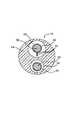
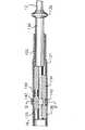
本発明の特に好ましい実施形態では、操縦可能な二方向電極カテーテル10が提供される。図1に示すように、カテーテル10には、近位端と遠位端を有する細長いカテーテル本体部12、カテーテル本体部12の遠位端にあるカテーテル先端部分14、及びカテーテル本体部12の近位端にある制御ハンドル16がある。
【0011】
図2、図3に示すように、カテーテル本体部12は、単一の軸に沿った内孔部又は中央内孔部18を有する細長いチューブ状構造体である。カテーテル本体部12は柔軟であり、即ち、曲がることができるが、長さに沿って実質的に圧縮性ではない。カテーテル本体部12はどのような構造でもよく、またどのような物質から製造されてもよい。好ましい構造では、ポリウレタン又はPEBAXから製造される外壁20を含む。好ましくは、外壁20にステンレス鋼等の編込みメッシュを埋め込みカテーテル本体部12のねじれ剛性を高め、制御ハンドル16が回転したら、カテーテル先端部分14がそれに応じて回転するようにする。
【0012】
カテーテル10の全体長と直径は用途により変わる。好ましいカテーテル10の全体長は約120cm(約48インチ)である。カテーテル本体部12の外径は重要ではないが、好ましくは、約2.6mm(約8フレンチ)以下である。好ましくは、外壁20の内面は剛性チューブ22と並ぶ。剛性チューブ22は好ましくはナイロン、ポリイミド等の適当な物質から製造できる。剛性チューブ22は編込み外壁20に沿って高いたわみ、ねじれ安定性を付与するが、同時にカテーテル本体部12の壁厚を最小にして中央内孔部18の直径を最大にする。剛性チューブ22の外径は外壁20の内径とほぼ同じか少し小さい。特に好ましいカテーテル10では、外径は約2.3mm(約0.092インチ)であり、内孔部の直径は約1.3mm(約0.052インチ)である。
【0013】
図4、図5に示すように、カテーテル先端部分14は、第一の軸ずれ内孔部26と第二の軸ずれ内孔部28を有する柔軟性チューブ24の短い一部を含む。柔軟性チューブ24は、好ましくはカテーテル本体部20に比べてより柔軟な適当な非毒性物質から製造される。この構成物質は編込みポリウレタン、即ち、編込みステンレス鋼等のメッシュが埋め込まれたポリウレタンである。カテーテル先端部分14の外径は、カテーテル本体部12と同様に、好ましくは約2.3mm(約7フレンチ)以下であり、より好ましくは約2.1mm(約6.5フレンチ)以下である。
【0014】
軸ずれ内孔部26,28はカテーテル先端部分14の対向する半分を通って延びる。軸ずれ内孔部26,28は非対称であり交換できない。第一の軸ずれ内孔部26は第二の軸ずれ内孔部28より小さい。カテーテル直径が2.6mm又は2.3mm(8フレンチ又は7フレンチ)でカテーテル先端部分が2.1mm(6.5フレンチ)のとき、第一の軸ずれ内孔部26の直径は、好ましくは約0.46mm(約0.018インチ)乃至約0.64mm(約0.025インチ)、より好ましくは約0.46mm(約0.018インチ)乃至約0.56mm(約0.022インチ)である。第二の軸ずれ内孔部28の直径は、好ましくは約0.56mm(約0.022インチ)乃至約0.76mm(約0.030インチ)、より好ましくは約0.66mm(約0.026インチ)乃至約0.71mm(約0.028インチ)である。
【0015】
1つの直径に沿って3つでなく2つの内孔部を用いているので、このデザインは一方向湾曲操縦可能カテーテルの簡単な構造を保っている。このようなカテーテルは米国特許再発行第34,502号に記載されており、この特許は参考としてここに援用する。
【0016】
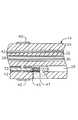
図2に、カテーテル本体部12をカテーテル先端部分14に取り付ける好ましい手段を示す。カテーテル先端部分14の近位端には、カテーテル本体部12の外壁20の内面が入る外周ノッチ34がある。カテーテル先端部分14とカテーテル本体部12は接着剤等により接続する。カテーテル先端部分14とカテーテル本体部14を接続する前に、剛性チューブ22をカテーテル本体部12に挿入する。剛性チューブ22の遠位端は、ポリウレタン接着剤等で接着結合を形成して、カテーテル本体部12の遠位端付近に固着する。好ましくは、カテーテル本体部12の遠位端と剛性チューブ22の遠位端の間に小さな隙間(例えば約3mm)を設け、カテーテル本体部12にカテーテル先端部分14のノッチ34を受ける空間を与える。剛性チューブ22の近位端に力を加え、剛性チューブ22を加圧しながら、速乾性接着剤(例えばSuper Glue(登録商標))を用いて剛性チューブ22と外壁20の間に第一の接着剤結合(図示せず)を形成する。その後、乾燥は遅いがより強力な接着剤(例えばポリウレタン)を用いて剛性チューブ22の近位端と外壁20の間に第二の接着剤結合を形成する。
【0017】
スペーサ36がカテーテル本体部12内で剛性チューブ22の遠位端とカテーテル先端部分14の近位端の間にある。好ましくは、スペーサ36は、カテーテル先端部分14の構成物質(例えばポリウレタン)より硬いが、剛性チューブ22の構成物質(例えばポリイミド)程硬くない物質から製造する。好ましくは、スペーサ36はTeflon(登録商標)から製造する。スペーサ36の長さは、好ましくは約0.64cm(約0.25インチ)乃至約1.9cm(約0.75インチ)であり、より好ましくは約1.3cm(約0.50インチ)である。好ましくは、スペーサ36の外径と内径は剛性チューブ22の外径と内径とほぼ同じである。スペーサ36はカテーテル本体部12とカテーテル先端部分14の連結部において柔軟性を変えて、折れたりよじれたりすることなくスムーズに曲がることを可能にする。
【0018】
図示する実施形態では、カテーテル先端部分14の遠位端に先端電極38を取り付ける。カテーテル先端部分14の一定の長さに沿ってリング状電極40を取り付ける(図4参照)。リング状電極40の長さは重要ではないが、好ましくは約1mm乃至約3mmである。所望によりリング電極を追加できる。複数のリング電極を使用するとき、リング電極はそれらの端が接しない限り所望の様式で離して配置できる。
【0019】
先端電極38とリング状電極40は各々別々のリードワイヤ30に接続する。各リードワイヤ30は、カテーテル先端部分14の第二の軸ずれ内孔部28、カテーテル本体部12の中央内孔部18及び制御ハンドル16を通って延びる。各リードワイヤ30の近位端は制御ハンドル16の近位端から外へ延び、適当なコネクタに接続する。このコネクタは適当なモニター、エネルギー源等にプラグ又は他の方法で接続する。
【0020】
リードワイヤ30は従来技術により先端電極38とリング状電極40に接続する。好ましくは、リードワイヤ30ははんだ等で先端電極38と接続する。好ましくは、リードワイヤ30は以下のようにしてリング状電極40と接続する。始めに、チューブ24に小さな孔を開ける。例えば、針をチューブ24に挿入し十分に針を加熱して永続的な孔を形成して、このような孔を形成する。次に、リードワイヤ30をマイクロホック等を用いて孔に引き込む。リードワイヤ30の端のコーティングを剥がしてリング状電極40の下側に溶接する。その後、これを孔の所定の位置に移してポリウレタン接着剤等を用いて所定の場所に固定する。
【0021】
2つの引張りワイヤ32がカテーテル10を通って延びる。各引張りワイヤ32は、制御ハンドル16からカテーテル本体部12の中央内孔部18を通り、カテーテル先端部分14の軸ずれ内孔部26,28のいずれかに入る。以下に詳細に説明するが、各引張りワイヤ32の近位端は制御ハンドル16内に固定され、その遠位端はカテーテル先端部分14に固定される。
【0022】
各引張りワイヤ32はステンレス鋼又はニチノール等の適当な金属から製造する。好ましくは、各引張りワイヤ32はTeflon(登録商標)等のコーティングによりコートされる。各引張りワイヤ32の直径は、好ましくは約0.15mm(約0.006インチ)乃至約0.25mm(約0.010インチ)である。好ましくは、引張りワイヤ32の直径は両方共同じである。
【0023】
各引張りワイヤ32はカテーテル先端部分14の遠位端近くに固定される。図4に示す実施形態では、引張りワイヤ32は両方共溶接等により先端電極38に固定される。
【0024】
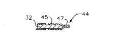
別の実施形態では、第一の軸ずれ内孔部26にある引張りワイヤ32はカテーテル先端部分14の側壁に固定する。図6乃至図8に示すように、好ましくは引張りワイヤ32の遠位端はアンカー44に接続する。アンカー44は、クリンピング等により引張りワイヤ32の遠位端に固着される金属チューブ45(例えば皮下ストック(hypodermic stock)の短いセグメント)により形成される。このチューブは引張りワイヤ32の遠位端を短い距離だけ超えて延びる部分を有する。ステンレス鋼リボン等の一部から製造したクロスピース47を、金属チューブの遠位端に対して横切った位置ではんだ付け又は溶接する。これは操作中は平らになる。このようにしてT−バーアンカー44を形成する。切り欠きをカテーテル先端部分14のサイドに形成し、引張りワイヤ32が通っている軸ずれ内孔部26に開口を形成する。クロスピース47は切り欠き内に横方向にある。クロスピース47を形成するリボンの長さは軸ずれ内孔部26に開く開口の直径より長いので、アンカー44は軸外れ内孔部26内へ完全に引き込まれない。その後、切り欠きをポリウレタン接着剤等でシールして滑らかな外面を形成する。接着剤は軸ずれ内孔部26内に流れ、アンカーを堅固に固定する。ポリイミドチューブ等の形態のトンネルを設けてリードワイヤ30を接着剤内に通して、第二の軸ずれ内孔部28を同じ引張りワイヤアンカー構造にすることができる。当業者は引張りワイヤ32をカテーテル先端部分14に固定する他の手段を認識でき、これらは本発明の範囲内に含まれる。
【0025】
カテーテル10は、さらに、2つの圧縮コイル46を含み、各圧縮コイルは対応する引張りワイヤを囲む。各圧縮コイル46はステンレス鋼等の適当な金属から製造する。各圧縮コイル46を堅固に巻いて、柔軟性を付与し、即ち、曲げることができるが、圧縮には抵抗する。各圧縮コイル46の内径は対応する引張りワイヤ32の直径より少し大きい。例えば、引張りワイヤ32の直径が約0.18mm(約0.007インチ)のとき、対応する圧縮コイル46の内径は、好ましくは約0.20mm(約0.008インチ)である。引張りワイヤ32のコーティングにより、引張りワイヤは圧縮コイル46内を自由にスライドできる。各圧縮コイル46の外面はその長さのほとんどに沿って柔軟な非導電性鞘48で覆われ、中央内孔部18の中で圧縮コイル46とリードワイヤ30が接触するのを防ぐ。好ましくは、非導電性鞘48は壁の薄いポリイミドチューブから製造する。
【0026】
カテーテル本体12の遠位端において、2つの圧縮コイル46が剛性チューブ22とスペーサ36内で直径方向に対向して配置されており、カテーテル先端部分14の2つの軸ずれ内孔部26,28と整列することができる。圧縮コイル46と剛性チューブ22は、圧縮コイル46が剛性チューブ22内にスライド可能に嵌合するような大きさである。このデザインでは、リードワイヤ30は圧縮コイルの配列を乱すことなく2つの圧縮コイル46の周囲にある。
【0027】
圧縮コイル46はポリウレタン接着剤等によりカテーテル本体部12内に固定される。各圧縮コイル46はその近位端においてカテーテル本体部12の剛性チューブ22の近位端に接着剤結合(図示せず)により固定される。剛性チューブ22を使用しないとき、各圧縮コイルはカテーテル本体部12の外壁20に直接固定される。
【0028】
各圧縮コイル46の遠位端はカテーテル本体部12内の剛性チューブ22の遠位端に接着剤結合52により固定される、また、剛性チューブ22を使用しないときはカテーテル本体部12の外壁20の遠位端に直接固定される。さもなければ、圧縮コイル46の遠位端をカテーテル先端部分14の軸ずれ内孔部26,28内に延ばして、その遠位端をカテーテル先端部分14の近位端に接着剤結合により固定してもよい。図示する実施形態では、圧縮コイル46を各々鞘48で囲む場合、鞘が圧縮コイルに確実に高い信頼性で接着するように注意しなければならない。リードワイヤ30も接着剤結合内に固定できる。しかし、所望により、接着剤結合において、リードワイヤの周囲にプラスチックチューブ等の形態のトンネルを設けて、リードワイヤが接着剤結合内でスライド可能となるようにできる。
【0029】
好ましくは、各圧縮コイル46の近位端および遠位端の両方の接着剤結合はポリウレタン接着剤等を含む。接着剤はシリンジ等によりカテーテル本体部12の外面と中央内孔部18の間に形成した孔を通して入れることができる。このような孔は、例えば、針等で外壁18と剛性チューブ22を穿孔し、永続的な孔が形成される程十分に加熱して、形成する。その後、接着剤を孔を通して圧縮コイル46の外面へ導入し、外周囲の周りに運んで、各圧縮コイル46を囲む各鞘48の周囲全体に接着剤結合を形成する。接着剤がコイルの端まで届いて引張りワイヤ32がコイル46内でスライドできなくならないように注意しなければならない。
【0030】
各引張りワイヤ32は軸ずれ内孔部26,28内でプラスチック鞘42で囲まれる。鞘42は好ましくはTeflon(登録商標)で製造する。プラスチック鞘42は、カテーテル先端部分14が曲がるとき、引張りワイヤ32がカテーテル先端部分14の壁内に切り込むことを防ぐ。各鞘42は各引張りワイヤ32の遠位端付近で終わる。さもなければ、各引張りワイヤ32を圧縮コイルで取り囲み、カテーテル本体部を通って延びる圧縮コイルに対して巻線が長手方向に広がって、取り囲む圧縮コイルが曲がることも圧縮することもできるようにする。
【0031】
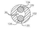
制御ハンドル16を適当に操縦して、引張りワイヤ32をカテーテル本体部12に対して長手方向に動かすと、カテーテル先端部分14が曲がる。本発明に使用する適当な二方向制御ハンドルを図9、図13、図15に示す。図9、図10、図11、図12に示すように、制御ハンドル16はほぼチューブ状のハンドルハウジング102を有する。ハウジング102は適当な硬い物質から製造できる。ハウジング102には、1つの軸方向の遠位ピストンチャンバ131と2つのより小さな近位ピストンチャンバ135の、3つのピストンチャンバがある。好ましくは、近位ピストンチャンバ135はハウジング内で直径方向に対向し、遠位ピストンチャンバ131と重なる。スライド可能遠位ピストン130が遠位ピストンチャンバ131内に取り付けられ、ハウジング102の遠位端から延びる。遠位ピストン130には、遠位端に親指置き132があり、軸方向に路133がある。カテーテル本体部12の近位端は接着剤等により軸路133内の遠位ピストン130に取り付けられる。引張りワイヤ32とリードワイヤ30が遠位ピストン130の軸路133を通って延びる。遠位ピストン130の近方には、2つのスライド可能な近位ピストン134が近位ピストンチャンバ135内にある。近位ピストン134は適当な物質で製造できる。好ましくはアルミニウムである。長さに沿ったある位置で、各引張りワイヤ32の近位端を近位ピストン134に固定する。引張りワイヤ32は、適当な手段、例えば上述した連結手段等により、近位ピストン134に固着できる。
【0032】
この構成では、親指置き132を押して遠位ピストン130をハンドルハウジング102に対して遠方に動かすと、カテーテル本体部12、引張りワイヤ32及び引張りワイヤが接続する近位ピストン134が遠方に動く。しかし、両方の引張りワイヤとそれらの近位ピストンが同時に動くと先端部14が曲がらない。従って、近位ピストン134が同時に動くのを防止する手段が設けられる。
【0033】
引張りワイヤ32が同時に動くのを防ぐ手段は、一方(両方ではない)の近位ピストン134の動きを固定、即ち防止する手段を含む。このことは、各近位ピストン134の一定長さに沿って円周部分を切り欠いて形成した周囲ノッチ140と、選択した1つの近位ピストン134の周囲ノッチ140と係合する手段とを組み合わせて実施する。
【0034】
好ましい係合手段は、図9、図10に示すように、ハンドルハウジング102を直径方向に貫いて延び、ハウジングの各サイドから少し出る可動バー142を含む。可動バー142は近位ピストン134の周囲ノッチ140に対応する位置で、ハウジングの各サイドでボタンのようなものを形成する。図13、図14に示すように、バー142にはほぼ楕円形のスロット146がある。近位ピストン134は両方共スロット146を通って延びる。スロット146の幅は近位ピストン134の直径より少し大きい。バー142の高さは周囲ノッチ140の長さより小さく、バー142はノッチ140に受け止められ係合する。スロット146の長さは、一度に1つだけの近位ピストン134が長さ方向に動けるように選択される。即ち、図13に示すように、バー142は、スロット146の端が1つの近位ピストン134の周囲ノッチを係合するまで、第一の方向に動く。この構成では、係合する近位ピストンはバー142により長手方向に動くのを妨げられるが、他の近位ピストンはスロット146を通って自由に動ける。バー142が他方に動くと、既に係合していた近位ピストンは自由に長手方向に動けるようになり、自由に動いていた近位ピストンが係合する。
【0035】
一方の近位ピストン134がバー142と係合すると、それがそこに接続する引張りワイヤ32に対して固定アンカーとして作動する。従って、親指置き132を押して遠位ピストン130をハウジング102に対して遠方に動かすと、カテーテル本体部12は固定された引張りワイヤ32に対して遠方に動く。この結果、カテーテル先端部分14は、この引張りワイヤを運ぶ軸ずれ内孔部の方向に曲がる。反対の近位ピストンが係合すると、カテーテル先端部分は反対方向に曲がる。
【0036】
他の実施形態の二方向制御ハンドルを図15に示す。このハンドル16は図9、図13に示すハンドルと大体同じであるが、近位ピストン134がほぼ円柱形でない。代わりに、各近位ピストン134は横断面がほぼ半円の遠位部を有し、半円の遠位部の平らなサイドはハンドル16の中央を向いている。各近位ピストン134の近位部はほぼ円柱形で、近位ピストンの遠位部と近位部の連結部にはステップ139が形成される。各近位ピストン134は前述の実施形態で説明した近位ピストンのように、ノッチ140を有する。各近位ピストン134にはステップ139において小穴(ボア(bore))150を通して対応する引張りワイヤ32が入り、引張りワイヤ32は近方に選択した距離だけ延びる。各近位ピストン134の近位端には、大きな遠位穴(ボア)152があり、遠方に延びて小穴150と連通する。各引張りワイヤ32の近位端にはアンカー154があり、アンカー154はスライド可能に大きな遠位穴152内に入るが、大きすぎて小穴150まで通ることはできない。アンカー154は、例えば、引張りワイヤ32の近位端を皮下ストック等にはんだ付けして形成できる。
【0037】
図15に示す実施形態では、制御ハンドル16の近位端にはプラグ156がある。プラグ156の遠位端にはネジ山があり、ハンドル本体102の近位端にあるネジ山と対応する。保護チューブ158がプラグ156から遠方に延びる。保護チューブ158は好ましくは金属から製造され、そこを、遠位ピストン130内の軸路133を通って延びるリードワイヤ30及び他のケーブル、ワイヤ等が通ることができる。プラグ156は適当なコネクタ(図示せず)を含むむことができ、例えば、リードワイヤ30と適当なモニター及び/又はRFエネルギー源との間の電気的接続を容易にする。
【0038】
他のどのような適当な二方向制御ハンドルでも本発明に使用できる。このようなハンドルは、例えば、米国特許出願第08/924,611号、同第08/982,113号、同第09/134,009号、同第09/143,426号及び同第09/130,359号に記載されている。これらの特許出願の開示は参考としてここに援用する。
【0039】
他の実施形態では、1以上の軸ずれ内孔部を追加して設けることができ、軸ずれ内孔部には追加の部品、例えば、注入チューブ、光学ファイバー等を通すことができる。カテーテル10の意図する用途によっては、温度センサー、光学ファイバー、注入チューブ及び/又は電磁気センサー等の特徴物を追加して含むことができる。さらに、温度センター等の小さな部品は引張りワイヤとリードワイヤと共にカテーテル先端部分の第二の軸ずれ内孔部に通すことができる。
【0040】
上述の実施形態では、カテーテル本体部12の中央内孔部18は、電極リードワイヤ30の他に、2つの引張りワイヤ32、圧縮コイル46、存在するなら、熱電対ワイヤ、電磁気センサーケーブル、光学ファイバー又は注入チューブの路として用いられている。別の実施形態では、カテーテル本体部12が複数の内孔部を有していてもよい。しかし、カテーテル10を回転するとき単一の内孔部体の方がより良くコントロールできるので、単一の中央内孔部18が好ましい。単一の中央内孔部18では、引張りワイヤ32、圧縮コイル46及びリードワイヤ30がカテーテル本体部12内で自由に浮動できる。このようなワイヤが多数の内孔部内で制限されるなら、制御ハンドル16が回転するとエネルギーが生じ、その結果、例えば、ハンドル16を解放するとき又は湾曲して曲げるとき、カテーテル本体部12が逆回転したり、ひっくり返ったりし易くなる。これは両方とも望ましくない。
【0041】
本発明の好ましい実施形態について説明してきたが、当業者は、本発明の原理、精神、範囲から離れることなく、説明した構造を変えることができる。
【0042】
従って、前述の説明は、図面に示される正確な構造体だけに関係するのではなく、特許請求の範囲に沿ってそれを支持するものである。
【0043】
好適な実施態様を以下に示す。
(A)近位端、遠位端及び少なくとも1つの内孔部を有する細長いカテーテル本体部と、
近位端、遠位端及び直径方向に対向する第一の軸ずれ内孔部及び第二の軸ずれ内孔部を有する柔軟性チューブを有し、前記第一の軸ずれ内孔部は前記第二の軸ずれ内孔部よりも直径が小さく、前記カテーテル本体部の遠位端にあるカテーテル先端部分と、
第一の位置及び第二の位置の間を長手方向に動くことのできる少なくとも2つの可動部材を有し、前記カテーテル本体部の近位端にある制御ハンドルと、
各々近位端と遠位端を有する第一の引張りワイヤ及び第二の引張りワイヤと、
前記カテーテル先端部分に取り付けられる電極と、
前記電極に電気的に接続する遠位端を有し、前記カテーテル先端部分の第二の軸ずれ内孔部、前記カテーテル本体部の内孔部及び前記制御ハンドルを通って延びるリードワイヤとを含み、
前記各引張りワイヤの近位端は前記制御ハンドルの対応する可動部材に接続し、前記各引張りワイヤは前記制御ハンドルから前記カテーテル本体部の内孔部を通って延び、前記第一の引張りワイヤは前記カテーテル先端部分の第一の軸ずれ内孔部内に入り、前記第二の引張りワイヤは前記カテーテル先端部分の第二の軸ずれ内孔部内に入り、前記各引張りワイヤの遠位端は前記カテーテル先端部分に固定され、
1つの可動部材が前記カテーテル本体部に対して近位側に動くと、その可動部材に対応する引張りワイヤが前記カテーテル本体部に対して近位側に動き、前記カテーテル先端部分がその引張りワイヤが延びる軸ずれ内孔部の方向に曲がる二方向カテーテル。
(1)さらに、近位端と遠位端を有し、各々が各引張りワイヤを囲んで前記カテーテル本体部を通って延びる、2つの圧縮コイルを有し、前記各圧縮コイルの近位端は前記カテーテル本体部の近位端付近に固定され、前記各圧縮コイルの遠位端は前記カテーテル本体部の遠位端又は前記カテーテル先端部分の近位端付近に固定される実施態様(A)に記載の二方向カテーテル。
(2)前記カテーテル本体部が単一の内孔部を有する実施態様(A)に記載の二方向カテーテル。
(3)前記カテーテル先端部分に先端電極が取り付けられる実施態様(A)に記載の 二方向カテーテル。
(4)前記カテーテル先端部分に少なくとも1つのリング電極が取り付けられる実施態様(A)に記載の二方向カテーテル。
(5)前記カテーテル先端部分にリング電極と先端電極の両方が取り付けられる実施態様(A)に記載の二方向カテーテル。
【0044】
(6)前記カテーテル先端部分の直径が2.3mm(7フレンチ)以下である実施態様(A)に記載の二方向カテーテル。
(7)前記カテーテル先端部分の直径が2.1mm(6.5フレンチ)以下である実施態様(A)に記載の二方向カテーテル。
(8)前記第一の軸ずれ内孔部の直径が約0.46mm(約0.018インチ)乃至約0.64mm(約0.025インチ)である実施態様(A)に記載の二方向カテーテル。
(9)前記第一の軸ずれ内孔部の直径が約0.46mm(約0.018インチ)乃至約0.56mm(約0.022インチ)である実施態様(A)に記載の二方向カテーテル。
(10)前記第二の軸ずれ内孔部の直径が約0.56mm(約0.022インチ)乃至約0.076mm(約0.030インチ)である実施態様(A)に記載の二方向カテーテル。
【0045】
(11)前記第二の軸ずれ内孔部の直径が約0.66mm(約0.026インチ)乃至約0.71mm(約0.028インチ)である実施態様(A)に記載の二方向カテーテル。
(12)前記第一の軸ずれ内孔部の直径が約0.46mm(約0.018インチ)乃至約0.64mm(約0.025インチ)であり、前記第二の軸ずれ内孔部の直径が約0.56mm(約0.022インチ)乃至約0.76mm(約0.030インチ)である実施態様(A)に記載の二方向カテーテル。
(13)前記第一の軸ずれ内孔部の直径が約0.46mm(約0.018インチ)乃至約0.56mm(約0.022インチ)であり、前記第二の軸ずれ内孔部の直径が約0.66mm(約0.026インチ)乃至約0.71mm(約0.028インチ)である実施態様(A)に記載の二方向カテーテル。
(14)前記カテーテル先端部分の柔軟性チューブがステンレス鋼編込みを有する実施態様(A)に記載の二方向カテーテル。
(B)近位端、遠位端及び少なくとも1つの内孔部を有する細長いカテーテル本体部と、
近位端と遠位端を有し、さらに直径方向に対向する第一の軸ずれ内孔部及び第二の軸ずれ内孔部から本質的になる柔軟性チューブを有し、前記カテーテル本体部の遠位端にあるカテーテル先端部分と、
第一の位置及び第二の位置の間を長手方向に動くことのできる少なくとも2つの可動部材を有し、前記カテーテル本体部の近位端にある制御ハンドルと、
各々近位端と遠位端を有する第一の引張りワイヤ及び第二の引張りワイヤと、
前記カテーテル先端部分に取り付けられる電極と、
前記電極に電気的に接続する遠位端を有し、前記カテーテル先端部分の第二の軸ずれ内孔部、前記カテーテル本体部の内孔部及び前記制御ハンドルを通って延びるリードワイヤとを含み、
前記各引張りワイヤの近位端は前記制御ハンドルの対応する可動部材に接続し、前記各引張りワイヤは前記制御ハンドルから前記カテーテル本体部の内孔部を通って延び、前記第一の引張りワイヤは前記カテーテル先端部分の第一の軸ずれ内孔部内に入り、前記第二の引張りワイヤは前記カテーテル先端部分の第二の軸ずれ内孔部内に入り、前記各引張りワイヤの遠位端は前記カテーテル先端部分に固定され、
1つの可動部材が前記カテーテル本体部に対して近位側に動くと、その可動部材に対応する引張りワイヤが前記カテーテル本体部に対して近位側に動き、前記カテーテル先端部分がその引張りワイヤが延びる軸ずれ内孔部の方向に曲がる二方向カテーテル。
(15)前記カテーテル先端部分の柔軟性チューブがステンレス鋼編込みを有する実施態様(B)に記載の二方向カテーテル。
【0046】
(16)前記第一の軸ずれ内孔部は前記第二の軸ずれ内孔部より直径が小さい実施態様(B)に記載の二方向カテーテル。
(17)前記カテーテル先端部分の直径が2.3mm(7フレンチ)以下である実施態様(B)に記載の二方向カテーテル。
(18)前記カテーテル先端部分の直径が2.1mm(6.5フレンチ)以下である実施態様(B)に記載の二方向カテーテル。
(19)前記第一の軸ずれ内孔部の直径が約0.46mm(約0.018インチ)乃至約0.64mm(約0.025インチ)である実施態様(B)に記載の二方向カテーテル。
(20)前記第一の軸ずれ内孔部の直径が約0.46mm(約0.018インチ)乃至約0.56mm(約0.022インチ)である実施態様(B)に記載の二方向カテーテル。
【0047】
(21)前記第二の軸ずれ内孔部の直径が約0.56mm(約0.022インチ)乃至約0.76mm(約0.030インチ)である実施態様(B)に記載の二方向カテーテル。
(22)前記第二の軸ずれ内孔部の直径が約0.66mm(約0.026インチ)乃至約0.71mm(約0.028インチ)である実施態様(B)に記載の二方向カテーテル。
(23)前記第一の軸ずれ内孔部の直径が約0.46mm(約0.018インチ)乃至約0.64mm(約0.025インチ)であり、前記第二の軸ずれ内孔部の直径が約0.56mm(約0.022インチ)乃至約0.76mm(約0.030インチ)である実施態様(B)に記載の二方向カテーテル。
(24)前記第一の軸ずれ内孔部の直径が約0.46mm(約0.018インチ)乃至約0.56mm(約0.022インチ)であり、前記第二の軸ずれ内孔部の直径が約0.66mm(約0.026インチ)乃至約0.71mm(約0.028インチ)である実施態様(B)に記載の二方向カテーテル。
(C)引張りワイヤ及び引張りワイヤと少なくとも1つの電極リードワイヤがそれぞれ入る、直径方向に対向する第一の軸ずれ内孔部及び第二の軸ずれ内孔部を有する柔軟性チューブを有し、前記第一の軸ずれ内孔部は前記第二の軸ずれ内孔部よりも直径が小さい二方向カテーテル用先端部。
【0048】
【発明の効果】
以上の述べたように、本発明によれば、直径の小さい二方向カテーカルの先端部に2本の引張りワイヤと電極用のリードワイヤが通り、先端部にステンレス鋼等の編込みを設ける場合であっても、良好に湾曲可能で良好に操縦可能であり、外科医が電極を組織に適切に配置することができる電極カテーテルを提供できる効果がある。
【図面の簡単な説明】
【図1】本発明のカテーテルの一実施形態の側面図である。
【図2】本発明のカテーテルの一実施形態におけるカテーテル本体部とカテーテル先端部分の連結部の側断面図である。
【図3】ライン3−3に沿った図2のカテーテル本体部の横断面図である。
【図4】図2のカテーテル先端部分の遠位端の側断面図である。
【図5】ライン5−5に沿った図4のカテーテル先端部分の横断面図である。
【図6】本発明のカテーテル先端部の横断面図であり、引張りワイヤがカテーテル先端部分の側壁に固定されているのを示す図である。
【図7】好ましい引張りワイヤT−バーアンカーの縦断面図である。
【図8】90°回転した図7の引張りワイヤT−バーアンカーの縦断面図であり、端にクロスピースを示す図である。
【図9】本発明のカテーテルに使用するのに適した二方向制御ハンドルの側断面図である。
【図10】ラインA−Aに沿った図9の二方向制御ハンドルの縦断面図である。
【図11】ラインB−Bに沿った図9の二方向制御ハンドルの縦断面図である。
【図12】ラインC−Cに沿った図9の二方向制御ハンドルの縦断面図である。
【図13】図9の二方向制御ハンドルの側断面図であり、ピストンがハンドルハウジングに対して遠方に延びているのを示す図である。
【図14】ラインD−Dに沿った図13の二方向制御ハンドルの縦断面図である。
【図15】本発明に使用するのに適した別の二方向制御ハンドルの側断面図である。
【符号の説明】
10 二方向カテーテル
12 カテーテル本体部
14 カテーテル先端部分
16 制御ハンドル
18 中央内孔部(カテーテル本体の内孔部)
24 柔軟性チューブ
26 第一の軸ずれ内孔部
28 第二の軸ずれ内孔部
30 リードワイヤ
32 引張りワイヤ
38 先端電極
40 リング状電極
134 ピストン(可動部材)[0001]
BACKGROUND OF THE INVENTION
The present invention relates to a bendable catheter, and more particularly to an electrode catheter that is bendable in two directions.
[0002]
[Background Art and Problems to be Solved by the Invention]
Cardiac blood lumen catheters with steerable or bendable tips are useful in many applications and represent a significant improvement over catheters with fixed tips. This is particularly useful in the field of electrophysiology where high frequency (radio frequency) ablation of heart tissue to interrupt abnormal electrical pathways in the heart. In general, ablation catheters have one or more electrodes attached to the distal end. The steerable catheter helps the surgeon move the distal end of the catheter to properly place the electrode on the tissue to be ablated.
[0003]
There are several useful configurations for steerable tip catheters. For example, U.S. Patent Reissue 34,502 shows a catheter having a housing with a control handle having a piston chamber at the distal end. The disclosure of this patent is incorporated herein by reference. The piston is attached to the piston chamber so that it can be moved in the longitudinal direction. The proximal end of the elongated tubular catheter body is attached to the piston. A pull wire is attached to the housing and extends through the piston and catheter body into the off-axis bore at the catheter tip. Secure the distal end of the puller wire to the tip of the catheter. In this configuration, when the piston moves longitudinally with respect to the housing, the catheter tip is bent.
[0004]
Bidirectional catheters are designed to bend in one direction by a first puller wire and in the opposite direction of the same plane by a second puller wire. In such a configuration, the puller wire extends into the opposing off-axis lumen at the distal end of the catheter. The puller wires and their corresponding bores must be placed along the diameter of the catheter tip so that the catheter tip can bend in both directions in the same plane. Also, in an ablation catheter, an electrode lead wire must be provided at the distal end. Generally, an inner hole is added and an electrode lead wire is included therein. The distal tip has two puller wire bores along the diameter, but the distal tip of a relatively small diameter (eg, 2.1 mm (6.5 French or less)) has three bores. It is difficult to design to pass through. This is particularly difficult when using a tip structure knitted with stainless steel, or when such braids are around all inner holes.
[0005]
[Means for Solving the Problems]
The present invention provides a bidirectional electrode catheter that overcomes the shortcomings of small diameter bidirectional catheters. The catheter has a pair of off-axis lumens along the diameter for passing the puller wire, and the electrode lead wire extends into one of the puller wire lumens. The inner hole portion including both the lead wire and the pull wire is diametrically opposed to the inner hole portion including only the other pull wire, and preferably, the diameter is larger than the inner hole portion including only the other pull wire. large.
[0006]
In one embodiment, the bi-directional catheter of the present invention includes an elongated catheter body, a catheter tip and a control handle. The body has a proximal end, a distal end and at least one lumen therethrough. The catheter tip portion at the distal end of the catheter body has a proximal end, a distal end and at least two diametrically opposed off-axis lumens.
[0007]
The control handle at the proximal end of the catheter body has at least two movable members that can move longitudinally between a first position and a second position. The first pull wire and the second pull wire each have a proximal end and a distal end and extend through the catheter body. The proximal end of each puller wire connects with a corresponding movable member of the control handle. Each puller wire extends from the control handle through the bore of the catheter body. The first puller wire extends into a first off-axis lumen in the catheter tip and the second puller wire extends into a second off-axis lumen in the catheter tip. The distal end of each puller wire is secured to the catheter tip. When one of the movable members moves proximally with respect to the catheter body, the puller wire corresponding to the movable member moves proximally with respect to the catheter body, and the distal end portion of the catheter passes through the inner hole through which the puller wire passes. Turn in the direction of the part.
[0008]
The electrode is attached to the catheter tip. The electrode may be a tip electrode or a ring electrode. Preferably, a tip electrode and at least one ring electrode are attached to the catheter tip portion. A lead wire is provided on each electrode and the distal end of the lead wire is electrically connected to the corresponding electrode. Each lead wire passes through the second off-axis bore in the catheter tip and the bore in the catheter body, into the control handle, and continues to the connector.
[0009]
DETAILED DESCRIPTION OF THE INVENTION
The foregoing and other features and advantages of the present invention may be better understood with reference to the drawings and the following detailed description.
[0010]
In a particularly preferred embodiment of the present invention, a steerable
[0011]
As shown in FIGS. 2 and 3, the
[0012]
The overall length and diameter of the
[0013]
As shown in FIGS. 4 and 5, the
[0014]
The off-axis bores 26, 28 extend through opposite halves of the
[0015]
This design keeps the simple structure of a one-way curved steerable catheter because it uses two lumens along one diameter instead of three. Such a catheter is described in US Patent Reissue 34,502, which is hereby incorporated by reference.
[0016]
FIG. 2 shows a preferred means for attaching the
[0017]
A spacer 36 is in the
[0018]
In the illustrated embodiment, a
[0019]
The
[0020]
The
[0021]
Two
[0022]
Each
[0023]
Each
[0024]
In another embodiment, the
[0025]
[0026]
At the distal end of the
[0027]
The
[0028]
The distal end of each
[0029]
Preferably, the adhesive bond at both the proximal and distal ends of each
[0030]
Each
[0031]
When the control handle 16 is properly maneuvered and the
[0032]
In this configuration, pushing the
[0033]
The means for preventing the
[0034]
The preferred engagement means includes a
[0035]
When one
[0036]
Another embodiment of a two-way control handle is shown in FIG. The
[0037]
In the embodiment shown in FIG. 15, there is a
[0038]
Any other suitable two-way control handle can be used in the present invention. Such handles include, for example, U.S. patent application Ser. Nos. 08 / 924,611, 08 / 982,113, 09 / 134,009, 09 / 143,426, and 09/143. 130,359. The disclosures of these patent applications are incorporated herein by reference.
[0039]
In other embodiments, one or more off-axis bores can be provided and additional components, such as injection tubes, optical fibers, etc., can be passed through the off-axis bores. Depending on the intended use of the
[0040]
In the above-described embodiment, the
[0041]
While preferred embodiments of the invention have been described, those skilled in the art can alter the described structures without departing from the principles, spirit, or scope of the invention.
[0042]
Accordingly, the foregoing description is not concerned solely with the precise structure shown in the drawings, but is supported in accordance with the claims.
[0043]
A preferred embodiment is shown below.
(A) an elongate catheter body having a proximal end, a distal end and at least one lumen;
A flexible tube having a proximal end, a distal end and a diametrically opposed first off-axis bore and a second off-axis bore, wherein the first off-axis bore is A catheter tip portion that is smaller in diameter than the second off-axis bore and at the distal end of the catheter body;
A control handle at the proximal end of the catheter body having at least two movable members movable longitudinally between a first position and a second position;
A first pull wire and a second pull wire each having a proximal end and a distal end;
An electrode attached to the catheter tip,
A distal end electrically connected to the electrode and including a second off-axis bore in the catheter tip portion, a bore in the catheter body and a lead wire extending through the control handle ,
The proximal end of each pull wire connects to a corresponding movable member of the control handle, each pull wire extends from the control handle through the bore of the catheter body, and the first pull wire is The catheter tip portion enters a first off-axis lumen, the second puller wire enters a second off-axis bore of the catheter tip portion, and the distal end of each pull wire is the catheter Fixed to the tip,
When one movable member moves proximally with respect to the catheter body, the pull wire corresponding to the movable member moves proximally with respect to the catheter body, and the catheter tip portion moves with the pull wire. A bi-directional catheter that bends in the direction of the extending off-axis bore.
(1) and further comprising two compression coils each having a proximal end and a distal end, each extending around the puller wire and extending through the catheter body, wherein the proximal end of each compression coil is Fixed near the proximal end of the catheter body, and the distal end of each compression coil is fixed near the distal end of the catheter body or the proximal end of the catheter tip portionEmbodiment (A)A bi-directional catheter according to 1.
(2) The catheter body has a single inner hole.Embodiment (A)A bi-directional catheter according to 1.
(3) A tip electrode is attached to the catheter tip.Embodiment (A)A bi-directional catheter as described in.
(4) At least one ring electrode is attached to the catheter tip.Embodiment (A)A bi-directional catheter according to 1.
(5) Both the ring electrode and the tip electrode are attached to the tip portion of the catheterEmbodiment (A)A bi-directional catheter according to 1.
[0044]
(6) The diameter of the catheter tip is 2.3 mm (7 French) or lessEmbodiment (A)A bi-directional catheter according to 1.
(7) The diameter of the catheter tip is 2.1 mm (6.5 French) or lessEmbodiment (A)A bi-directional catheter according to 1.
(8) The diameter of the first off-axis inner bore is about 0.46 mm (about 0.018 inch) to about 0.64 mm (about 0.025 inch).Embodiment (A)A bi-directional catheter according to 1.
(9) The diameter of the first off-axis bore is about 0.46 mm (about 0.018 inch) to about 0.56 mm (about 0.022 inch).Embodiment (A)A bi-directional catheter according to 1.
(10) The diameter of the second off-axis inner hole portion is about 0.022 inch to about 0.030 inch.Embodiment (A)A bi-directional catheter according to 1.
[0045]
(11) The diameter of the second off-axis inner hole is about 0.66 mm (about 0.026 inch) to about 0.71 mm (about 0.028 inch).Embodiment (A)A bi-directional catheter according to 1.
(12) The diameter of the first off-axis bore is about 0.016 inch to about 0.025 inch, and the second off-axis bore portion is Has a diameter of about 0.56 mm (about 0.022 inch) to about 0.76 mm (about 0.030 inch).Embodiment (A)A bi-directional catheter according to 1.
(13) the diameter of the first off-axis bore is about 0.46 mm (about 0.018 inch) to about 0.56 mm (about 0.022 inch); Has a diameter of about 0.66 mm (about 0.026 inch) to about 0.71 mm (about 0.028 inch).Embodiment (A)A bi-directional catheter according to 1.
(14) The flexible tube at the distal end of the catheter has a braided stainless steelEmbodiment (A)A bi-directional catheter according to 1.
(B) an elongate catheter body having a proximal end, a distal end and at least one lumen;
A catheter having a proximal end and a distal end, and further comprising a flexible tube consisting essentially of a diametrically opposed first and second off-axis bores; A catheter tip at the distal end of the
A control handle at the proximal end of the catheter body having at least two movable members movable longitudinally between a first position and a second position;
A first pull wire and a second pull wire each having a proximal end and a distal end;
An electrode attached to the catheter tip,
A distal end electrically connected to the electrode and including a second off-axis bore in the catheter tip portion, a bore in the catheter body and a lead wire extending through the control handle ,
The proximal end of each pull wire connects to a corresponding movable member of the control handle, each pull wire extends from the control handle through the bore of the catheter body, and the first pull wire is The catheter tip portion enters a first off-axis lumen, the second puller wire enters a second off-axis bore of the catheter tip portion, and the distal end of each pull wire is the catheter Fixed to the tip,
When one movable member moves proximally with respect to the catheter body, the pull wire corresponding to the movable member moves proximally with respect to the catheter body, and the catheter tip portion moves with the pull wire. A bi-directional catheter that bends in the direction of the extending off-axis bore.
(15) The flexible tube at the distal end portion of the catheter has a stainless steel braid.Embodiment (B)A bi-directional catheter according to 1.
[0046]
(16) The first off-axis inner hole has a smaller diameter than the second off-axis inner hole.Embodiment (B)A bi-directional catheter according to 1.
(17) The diameter of the distal end portion of the catheter is 2.3 mm (7 French) or less.Embodiment (B)A bi-directional catheter according to 1.
(18) The diameter of the catheter tip is 2.1 mm (6.5 French) or lessEmbodiment (B)A bi-directional catheter according to 1.
(19) The diameter of the first off-axis inner hole is about 0.46 mm (about 0.018 inch) to about 0.64 mm (about 0.025 inch).Embodiment (B)A bi-directional catheter according to 1.
(20) The diameter of the first off-axis bore is about 0.46 mm (about 0.018 inch) to about 0.56 mm (about 0.022 inch).Embodiment (B)A bi-directional catheter according to 1.
[0047]
(21) The diameter of the second off-axis inner hole is about 0.56 mm (about 0.022 inch) to about 0.76 mm (about 0.030 inch).Embodiment (B)A bi-directional catheter according to 1.
(22) The diameter of the second off-axis inner hole portion is about 0.66 mm (about 0.026 inch) to about 0.71 mm (about 0.028 inch).Embodiment (B)A bi-directional catheter according to 1.
(23) The first off-axis bore has a diameter of about 0.46 mm (about 0.018 inch) to about 0.64 mm (about 0.025 inch); Has a diameter of about 0.56 mm (about 0.022 inch) to about 0.76 mm (about 0.030 inch).Embodiment (B)A bi-directional catheter according to 1.
(24) the first off-axis bore has a diameter of about 0.46 mm (about 0.018 inch) to about 0.56 mm (about 0.022 inch); Has a diameter of about 0.66 mm (about 0.026 inch) to about 0.71 mm (about 0.028 inch).Embodiment (B)A bi-directional catheter according to 1.
(C) having a flexible tube having a first axially offset inner hole part and a second axially offset inner hole part facing each other in a diametrical direction, each of which includes a tension wire and a tension wire and at least one electrode lead wire; The biaxial catheter distal end portion having a diameter smaller than that of the second off-axis bore portion.
[0048]
【The invention's effect】
As described above, according to the present invention, in the case where two pull wires and an electrode lead wire pass through the distal end portion of the two-way categorical having a small diameter, and a braid of stainless steel or the like is provided at the distal end portion. Even so, there is an effect that it is possible to provide an electrode catheter that can be bent well and can be steered, and that allows the surgeon to appropriately place the electrode on the tissue.
[Brief description of the drawings]
FIG. 1 is a side view of one embodiment of a catheter of the present invention.
FIG. 2 is a side sectional view of a connecting portion between a catheter main body and a catheter tip portion in an embodiment of the catheter of the present invention.
3 is a cross-sectional view of the catheter body of FIG. 2 taken along line 3-3.
4 is a side cross-sectional view of the distal end of the catheter tip portion of FIG. 2. FIG.
5 is a cross-sectional view of the catheter tip portion of FIG. 4 taken along line 5-5.
FIG. 6 is a cross-sectional view of the distal end portion of the catheter of the present invention, showing that the pull wire is fixed to the side wall of the distal end portion of the catheter.
FIG. 7 is a longitudinal sectional view of a preferred pull wire T-bar anchor.
8 is a longitudinal cross-sectional view of the pull wire T-bar anchor of FIG. 7 rotated 90 °, showing a crosspiece at the end.
FIG. 9 is a cross-sectional side view of a bi-directional control handle suitable for use with the catheter of the present invention.
10 is a longitudinal cross-sectional view of the two-way control handle of FIG. 9 along line AA.
11 is a longitudinal cross-sectional view of the two-way control handle of FIG. 9 along line BB.
12 is a longitudinal cross-sectional view of the two-way control handle of FIG. 9 taken along line CC.
13 is a cross-sectional side view of the two-way control handle of FIG. 9, showing the piston extending away from the handle housing.
14 is a longitudinal cross-sectional view of the two-way control handle of FIG. 13 along line DD.
FIG. 15 is a cross-sectional side view of another two-way control handle suitable for use with the present invention.
[Explanation of symbols]
10 Bidirectional catheter
12 Catheter body
14 catheter tip
16 Control handle
18 Central inner hole (Inner hole of catheter body)
24 Flexible tube
26 First off-axis bore
28 Second off-axis bore
30 Lead wire
32 Tensile wire
38 Tip electrode
40 Ring electrode
134 Piston (movable member)
Claims (12)
Translated fromJapanese近位端、遠位端、ならびに前記近位端および前記遠位端の間を延在する少なくとも1つの内孔部を有する細長いカテーテル本体部と、
前記カテーテル本体部の前記遠位端に設けられたカテーテル先端部分であって、
近位端、遠位端、ならびに直径方向に対向する第一の軸ずれ内孔部および第二の軸ずれ内孔部を有する柔軟性チューブを有し、
前記第一の軸ずれ内孔部は、前記第二の軸ずれ内孔部よりも直径が小さい、
カテーテル先端部分と、
前記カテーテル本体部の前記近位端に設けられた制御ハンドルであって、
第一の位置および第二の位置の間を長さ方向に動くことのできる少なくとも2つの可動部材を含む、
制御ハンドルと、
第一の引張りワイヤおよび第二の引張りワイヤであって、
各前記引張りワイヤは、近位端および遠位端を有し、
各前記引張りワイヤの前記近位端は、前記制御ハンドルの対応する前記可動部材に接続され、
各前記引張りワイヤは、前記制御ハンドルから前記カテーテル本体部の内孔部を通って延在し、
前記第一の引張りワイヤは、前記先端部分の前記第一の軸ずれ内孔部を延在し、
前記第二の引張りワイヤは、前記先端部分の前記第二の軸ずれ内孔部を延在し、
各前記引張りワイヤの前記遠位端は、前記カテーテル先端部分に固定される、
第一の引張りワイヤおよび第二の引張りワイヤと、
前記カテーテル先端部分に取り付けられる電極と、
前記電極に電気的に接続される遠位端を有するリードワイヤであって、
前記カテーテル先端部分の前記第二の軸ずれ内孔部、前記カテーテル本体部の内孔部、および前記制御ハンドルを通って延在する、
リードワイヤと、
を含み、
1つの前記可動部材が前記カテーテル本体部に対して近位側に動くと、当該可動部材に対応する前記引張りワイヤが、前記カテーテル本体部に対して近位側に動き、
前記引張りワイヤが、前記カテーテル本体部に対して近位側に動くことによって、前記カテーテル先端部分が、当該引張りワイヤが延在する前記軸ずれ内孔部の方向に偏向される、
二方向カテーテル。In a bi-directional catheter,
An elongate catheter body having a proximal end, a distal end, and at least one lumenextending between the proximal end and the distal end ;
A catheter tip portion provided at the distal end of the catheter body,
A flexible tube having a proximal end, a distal end, and a diametrically opposed firstand second off-axis bores;
The first off-axis lumenisnot smaller in diameter than the second off-axis lumen,
A catheter tip,
A control handle provided at the proximal end of the catheter body,
Comprising at least two movable members can move between a first positionand a second position in thelongitudinal direction,
A control handle;
Afirst puller wireand a second pull wire,
Each said puller wire has a proximal end and a distal end;
The proximal end of each puller wire is connected to the corresponding movable member of the control handle;
Each of the pull wires extends from the control handle through an inner bore of the catheter body,
The first pull wire extends the first off-axis inner hole portion of the tip portion,
The second puller wire extends through the second off-axis bore of the tip portion;
The distal end of each puller wire is secured to the catheter tip portion;
A first puller wire and a second puller wire;
An electrode attached to the catheter tip,
A lead wire to have a distal endwhich is electrically connected to said electrode,
The second off-axis lumen of the catheter tip section,extending through lumen of the catheterbody, and the controlhandle,
Lead wires,
Itincludes,
If one ofthe movable member is moved proximally relative to the catheter body,said puller wire corresponding tothe movablemember, moves proximally with respect to the catheter body,
The pulling wire moves proximally with respect to the catheter body, so that the catheter tip portion isdeflected in the direction of the off-axis lumen in whichthe pulling wireextends.
Bidirectional catheter.
近位端、遠位端、ならびに前記近位端および前記遠位端の間を延在する少なくとも1つの内孔部を有する細長いカテーテル本体部と、
前記カテーテル本体部の前記遠位端に設けられたカテーテル先端部分であって、
近位端および遠位端を有する柔軟性チューブを含み、
前記柔軟性チューブは、直径方向に対向する第一の軸ずれ内孔部および第二の軸ずれ内孔部から本質的になる、
カテーテル先端部分と、
前記カテーテル本体部の前記近位端に設けられた制御ハンドルであって、
第一の位置および第二の位置の間を長さ方向に動くことのできる少なくとも2つの可動部材を含む、
制御ハンドルと、
第一の引張りワイヤおよび第二の引張りワイヤであって、
各前記引張りワイヤは、近位端および遠位端を有し、
各前記引張りワイヤの前記近位端は、前記制御ハンドルの対応する前記可動部材に接続され、
各前記引張りワイヤは、前記制御ハンドルから前記カテーテル本体部の前記内孔部を通って延在し、
前記第一の引張りワイヤは、前記先端部分の前記第一の軸ずれ内孔部を延在し、
前記第二の引張りワイヤは、前記先端部分の前記第二の軸ずれ内孔部を延在し、
各前記引張りワイヤの前記遠位端は、前記カテーテル先端部分に固定される、
第一の引張りワイヤおよび第二の引張りワイヤと、
前記カテーテル先端部分に取り付けられる電極と、
前記電極に電気的に接続される遠位端を有するリードワイヤであって、
前記カテーテル先端部分の前記第二の軸ずれ内孔部、前記カテーテル本体部の内孔部、および前記制御ハンドルを通って延在する、
リードワイヤと、
を含み、
1つの前記可動部材が前記カテーテル本体部に対して近位側に動くと、当該可動部材に対応する前記引張りワイヤが、前記カテーテル本体部に対して近位側に動き、
前記引張りワイヤが、前記カテーテル本体部に対して近位側に動くことによって、前記カテーテル先端部分が、当該引張りワイヤが延在する前記軸ずれ内孔部の方向に偏向される、
二方向カテーテル。In a bi-directional catheter,
An elongate catheter body having a proximal end, a distal end, and at least one lumenextending between the proximal end and the distal end ;
A catheter tip portion provided at the distal end of the catheter body,
Includes a flexible tube to have a proximal endand a distal end,
The flexible tube consists essentiallyof a diametrically opposed first off-axis boreand a second off-axis bore.
A catheter tip,
A control handle provided at the proximal end of the catheter body,
Comprising at least two movable members can move between a first positionand a second position in thelongitudinal direction,
And thecontrol handle,
Afirst puller wireand a second pull wire,
Each said puller wire has a proximal end and a distal end;
The proximal end of each puller wire is connected to the corresponding movable member of the control handle;
Each of the pull wires extends from the control handle through the inner bore of the catheter body,
The first pull wire extends the first off-axis inner hole portion of the tip portion,
The second puller wire extends through the second off-axis bore of the tip portion;
The distal end of each puller wire is secured to the catheter tip portion;
A first puller wire and a second puller wire;
An electrode attached to the catheter tip,
A lead wire to have a distal endwhich is electrically connected to said electrode,
The second off-axis lumen of the catheter tip section,extending through lumen of the catheterbody, and the controlhandle,
Lead wires,
Itincludes,
If one ofthe movable member is moved proximally relative to the catheter body,said puller wire corresponding tothe movablemember, moves proximally with respect to the catheter body,
The pulling wire moves proximally with respect to the catheter body, so that the catheter tip portion isdeflected in the direction of the off-axis lumen in whichthe pulling wireextends.
Bidirectional catheter.
直径方向に対向する第一の軸ずれ内孔部および第二の軸ずれ内孔部を有する柔軟性チューブを含み、
前記第一の軸ずれ内孔部は、引張りワイヤを収容し、
前記第二の軸ずれ内孔部は、引張りワイヤおよび少なくとも1つの電極リードワイヤを収容し、
前記第一の軸ずれ内孔部は、前記第二の軸ずれ内孔部よりも直径が小さい、
二方向カテーテルの先端部分。At the tip of the bi-directional catheter,
Including a flexible tube having a first off-axis bore and a second off-axis bore that are diametrically opposed;
The first off-axis inner hole portionaccommodatesa pull wire,
The second off-axis boreaccommodatesa pull wireand at least one electrode lead wire;
The first off-axis lumenhas a smaller diameter than the second off-axislumen,
Tipportionof bi-directional catheter.
2つの圧縮コイル、をさらに含み、 Further comprising two compression coils,
各前記圧縮コイルは、遠位端および近位端を有し、 Each compression coil has a distal end and a proximal end;
各前記圧縮コイルは、各引張りワイヤを囲みながら、前記カテーテル本体部内を延在し、 Each compression coil extends within the catheter body while enclosing each puller wire,
各前記圧縮コイルの前記近位端は、前記カテーテル本体部の前記近位端の近くに固定して取り付けられ、 The proximal end of each compression coil is fixedly attached near the proximal end of the catheter body,
各前記圧縮コイルの前記遠位端は、前記カテーテル本体部の前記遠位端の近くまたは前記先端部分の前記近位端の近くに固定して取り付けられる、 The distal end of each compression coil is fixedly attached near the distal end of the catheter body or near the proximal end of the tip portion;
二方向カテーテル。 Bidirectional catheter.
前記カテーテル本体部は、1つの内孔部を有する、二方向カテーテル。 The catheter body is a bidirectional catheter having one inner hole.
前記先端部分は、先端電極を有する、二方向カテーテル。 The bi-directional catheter, wherein the distal portion has a distal electrode.
前記先端部分は、少なくとも1つのリング状電極を有する、二方向カテーテル。 The bi-directional catheter, wherein the distal portion has at least one ring electrode.
前記先端部分は、リング状電極および先端電極の両方を有する、二方向カテーテル。 The bi-directional catheter, wherein the tip portion has both a ring electrode and a tip electrode.
前記先端部分の直径は、2.3ミリメートル(7フレンチ)以下である、二方向カテーテル。 The two-way catheter, wherein the tip portion has a diameter of 2.3 millimeters (7 French) or less.
前記先端部分の直径は、2.1ミリメートル(6.5フレンチ)以下である、二方向カテーテル。 The tip portion has a diameter of 2.1 millimeters (6.5 French) or less.
前記第一の軸ずれ内孔部は、0.46ミリメートル(0.018インチ)〜0.64ミリメートル(0.025インチ)の直径を有する、二方向カテーテル。 The first off-axis lumen has a diameter of 0.46 millimeters (0.018 inches) to 0.64 millimeters (0.025 inches).
前記先端部分の前記柔軟性チューブは、ステンレス鋼の編み込みを含む、二方向カテーテル。 The bi-directional catheter, wherein the flexible tube of the distal portion includes a stainless steel braid.
Applications Claiming Priority (2)
| Application Number | Priority Date | Filing Date | Title |
|---|---|---|---|
| US205631 | 1998-12-03 | ||
| US09/205,631US6210407B1 (en) | 1998-12-03 | 1998-12-03 | Bi-directional electrode catheter |
Publications (2)
| Publication Number | Publication Date |
|---|---|
| JP2000197642A JP2000197642A (en) | 2000-07-18 |
| JP4152546B2true JP4152546B2 (en) | 2008-09-17 |
Family
ID=22762984
Family Applications (1)
| Application Number | Title | Priority Date | Filing Date |
|---|---|---|---|
| JP34384799AExpired - Fee RelatedJP4152546B2 (en) | 1998-12-03 | 1999-12-02 | Bi-directional electrode catheter |
Country Status (5)
| Country | Link |
|---|---|
| US (1) | US6210407B1 (en) |
| EP (1) | EP1005839B1 (en) |
| JP (1) | JP4152546B2 (en) |
| AT (1) | ATE266363T1 (en) |
| DE (1) | DE69917188T2 (en) |
Families Citing this family (162)
| Publication number | Priority date | Publication date | Assignee | Title |
|---|---|---|---|---|
| US8758400B2 (en) | 2000-01-05 | 2014-06-24 | Integrated Vascular Systems, Inc. | Closure system and methods of use |
| US6461364B1 (en) | 2000-01-05 | 2002-10-08 | Integrated Vascular Systems, Inc. | Vascular sheath with bioabsorbable puncture site closure apparatus and methods of use |
| US9579091B2 (en) | 2000-01-05 | 2017-02-28 | Integrated Vascular Systems, Inc. | Closure system and methods of use |
| US6391048B1 (en) | 2000-01-05 | 2002-05-21 | Integrated Vascular Systems, Inc. | Integrated vascular device with puncture site closure component and sealant and methods of use |
| US7842068B2 (en) | 2000-12-07 | 2010-11-30 | Integrated Vascular Systems, Inc. | Apparatus and methods for providing tactile feedback while delivering a closure device |
| US6475214B1 (en) | 2000-05-01 | 2002-11-05 | Biosense Webster, Inc. | Catheter with enhanced ablation electrode |
| DE60144328D1 (en) | 2000-09-08 | 2011-05-12 | Abbott Vascular Inc | Surgical clamp |
| US6626918B1 (en)* | 2000-10-06 | 2003-09-30 | Medical Technology Group | Apparatus and methods for positioning a vascular sheath |
| US8690910B2 (en) | 2000-12-07 | 2014-04-08 | Integrated Vascular Systems, Inc. | Closure device and methods for making and using them |
| US6623510B2 (en) | 2000-12-07 | 2003-09-23 | Integrated Vascular Systems, Inc. | Closure device and methods for making and using them |
| US6695867B2 (en) | 2002-02-21 | 2004-02-24 | Integrated Vascular Systems, Inc. | Plunger apparatus and methods for delivering a closure device |
| US7211101B2 (en) | 2000-12-07 | 2007-05-01 | Abbott Vascular Devices | Methods for manufacturing a clip and clip |
| US7806904B2 (en) | 2000-12-07 | 2010-10-05 | Integrated Vascular Systems, Inc. | Closure device |
| US7905900B2 (en) | 2003-01-30 | 2011-03-15 | Integrated Vascular Systems, Inc. | Clip applier and methods of use |
| IES20010547A2 (en) | 2001-06-07 | 2002-12-11 | Christy Cummins | Surgical Staple |
| US6913594B2 (en)* | 2001-12-31 | 2005-07-05 | Biosense Webster, Inc. | Dual-function catheter handle |
| US6733499B2 (en) | 2002-02-28 | 2004-05-11 | Biosense Webster, Inc. | Catheter having circular ablation assembly |
| US8956280B2 (en) | 2002-05-30 | 2015-02-17 | Intuitive Surgical Operations, Inc. | Apparatus and methods for placing leads using direct visualization |
| IES20030424A2 (en) | 2002-06-04 | 2003-12-10 | Robert Stevenson | Blood vessel closure clip and delivery device |
| US7588568B2 (en)* | 2002-07-19 | 2009-09-15 | Biosense Webster, Inc. | Atrial ablation catheter and method for treating atrial fibrillation |
| US7560269B2 (en)* | 2002-12-20 | 2009-07-14 | Acea Biosciences, Inc. | Real time electronic cell sensing system and applications for cytotoxicity profiling and compound assays |
| US20040034365A1 (en)* | 2002-08-16 | 2004-02-19 | Lentz David J. | Catheter having articulation system |
| US7087064B1 (en) | 2002-10-15 | 2006-08-08 | Advanced Cardiovascular Systems, Inc. | Apparatuses and methods for heart valve repair |
| US7485143B2 (en)* | 2002-11-15 | 2009-02-03 | Abbott Cardiovascular Systems Inc. | Apparatuses and methods for heart valve repair |
| US7981152B1 (en) | 2004-12-10 | 2011-07-19 | Advanced Cardiovascular Systems, Inc. | Vascular delivery system for accessing and delivering devices into coronary sinus and other vascular sites |
| US6945978B1 (en) | 2002-11-15 | 2005-09-20 | Advanced Cardiovascular Systems, Inc. | Heart valve catheter |
| US9149602B2 (en) | 2005-04-22 | 2015-10-06 | Advanced Cardiovascular Systems, Inc. | Dual needle delivery system |
| US8187324B2 (en) | 2002-11-15 | 2012-05-29 | Advanced Cardiovascular Systems, Inc. | Telescoping apparatus for delivering and adjusting a medical device in a vessel |
| US7335213B1 (en) | 2002-11-15 | 2008-02-26 | Abbott Cardiovascular Systems Inc. | Apparatus and methods for heart valve repair |
| US7331972B1 (en) | 2002-11-15 | 2008-02-19 | Abbott Cardiovascular Systems Inc. | Heart valve chord cutter |
| US7404824B1 (en)* | 2002-11-15 | 2008-07-29 | Advanced Cardiovascular Systems, Inc. | Valve aptation assist device |
| US7819866B2 (en) | 2003-01-21 | 2010-10-26 | St. Jude Medical, Atrial Fibrillation Division, Inc. | Ablation catheter and electrode |
| US7857828B2 (en) | 2003-01-30 | 2010-12-28 | Integrated Vascular Systems, Inc. | Clip applier and methods of use |
| US8398656B2 (en) | 2003-01-30 | 2013-03-19 | Integrated Vascular Systems, Inc. | Clip applier and methods of use |
| US8905937B2 (en) | 2009-02-26 | 2014-12-09 | Integrated Vascular Systems, Inc. | Methods and apparatus for locating a surface of a body lumen |
| US8202293B2 (en) | 2003-01-30 | 2012-06-19 | Integrated Vascular Systems, Inc. | Clip applier and methods of use |
| US8821534B2 (en) | 2010-12-06 | 2014-09-02 | Integrated Vascular Systems, Inc. | Clip applier having improved hemostasis and methods of use |
| US8758398B2 (en) | 2006-09-08 | 2014-06-24 | Integrated Vascular Systems, Inc. | Apparatus and method for delivering a closure element |
| US7163537B2 (en)* | 2003-06-02 | 2007-01-16 | Biosense Webster, Inc. | Enhanced ablation and mapping catheter and method for treating atrial fibrillation |
| US7101362B2 (en)* | 2003-07-02 | 2006-09-05 | St. Jude Medical, Atrial Fibrillation Division, Inc. | Steerable and shapable catheter employing fluid force |
| US7235070B2 (en)* | 2003-07-02 | 2007-06-26 | St. Jude Medical, Atrial Fibrillation Division, Inc. | Ablation fluid manifold for ablation catheter |
| US7678104B2 (en)* | 2003-07-17 | 2010-03-16 | Biosense Webster, Inc. | Ultrasound ablation catheter and method for its use |
| US10182734B2 (en)* | 2003-07-18 | 2019-01-22 | Biosense Webster, Inc. | Enhanced ablation and mapping catheter and method for treating atrial fibrillation |
| US6926711B2 (en)* | 2003-07-30 | 2005-08-09 | Cryocor, Inc. | Articulating catheter for cryoablation with reduced diameter section |
| US7998112B2 (en)* | 2003-09-30 | 2011-08-16 | Abbott Cardiovascular Systems Inc. | Deflectable catheter assembly and method of making same |
| US7077823B2 (en)* | 2003-11-19 | 2006-07-18 | Biosense Webster, Inc. | Bidirectional steerable catheter with slidable mated puller wires |
| US20050119644A1 (en)* | 2003-12-01 | 2005-06-02 | Koerner Richard J. | Articulating catheter tip with wedge-cuts |
| US20050177131A1 (en)* | 2004-02-09 | 2005-08-11 | Lentz David J. | Catheter articulation segment with alternating cuts |
| US7637903B2 (en)* | 2004-02-09 | 2009-12-29 | Cryocor, Inc. | Catheter articulation segment with alternating cuts |
| US20050197623A1 (en)* | 2004-02-17 | 2005-09-08 | Leeflang Stephen A. | Variable steerable catheters and methods for using them |
| US8046049B2 (en) | 2004-02-23 | 2011-10-25 | Biosense Webster, Inc. | Robotically guided catheter |
| US8007495B2 (en) | 2004-03-31 | 2011-08-30 | Biosense Webster, Inc. | Catheter for circumferential ablation at or near a pulmonary vein |
| IES20040368A2 (en) | 2004-05-25 | 2005-11-30 | James E Coleman | Surgical stapler |
| US7591799B2 (en)* | 2004-06-14 | 2009-09-22 | Biosense Webster, Inc. | Steering mechanism for bi-directional catheter |
| US7377906B2 (en)* | 2004-06-15 | 2008-05-27 | Biosense Webster, Inc. | Steering mechanism for bi-directional catheter |
| US20050283179A1 (en)* | 2004-06-17 | 2005-12-22 | Lentz David J | Introducer sheath |
| US7285108B2 (en)* | 2004-06-24 | 2007-10-23 | Cryocor, Inc. | Active system for deflecting a distal portion of a catheter into a hoop configuration |
| US7374553B2 (en)* | 2004-06-24 | 2008-05-20 | Cryocor, Inc. | System for bi-directionally controlling the cryo-tip of a cryoablation catheter |
| US7357797B2 (en)* | 2004-06-30 | 2008-04-15 | Cryocor, Inc. | System and method for varying return pressure to control tip temperature of a cryoablation catheter |
| US7717875B2 (en)* | 2004-07-20 | 2010-05-18 | St. Jude Medical, Atrial Fibrillation Division, Inc. | Steerable catheter with hydraulic or pneumatic actuator |
| US7753906B2 (en) | 2004-09-14 | 2010-07-13 | Richard Esposito | Catheter having anchoring and stabilizing devices |
| US7993350B2 (en) | 2004-10-04 | 2011-08-09 | Medtronic, Inc. | Shapeable or steerable guide sheaths and methods for making and using them |
| US8858495B2 (en) | 2004-12-28 | 2014-10-14 | St. Jude Medical, Atrial Fibrillation Division, Inc. | Five degree of freedom ultrasound catheter and catheter control handle |
| US7691095B2 (en) | 2004-12-28 | 2010-04-06 | St. Jude Medical, Atrial Fibrillation Division, Inc. | Bi-directional steerable catheter control handle |
| US8583260B2 (en) | 2004-12-28 | 2013-11-12 | St. Jude Medical, Atrial Fibrillation Division, Inc. | Long travel steerable catheter actuator |
| US7959601B2 (en) | 2005-02-14 | 2011-06-14 | Biosense Webster, Inc. | Steerable catheter with in-plane deflection |
| US7877151B2 (en)* | 2005-02-22 | 2011-01-25 | Cardiac Pacemakers, Inc. | Strategic combination of conductors in a lead assembly for a medical device |
| US7591784B2 (en)* | 2005-04-26 | 2009-09-22 | St. Jude Medical, Atrial Fibrillation Division, Inc. | Bi-directional handle for a catheter |
| US8376990B2 (en) | 2005-05-19 | 2013-02-19 | Biosense Webster, Inc. | Steerable catheter with distal tip orientation sheaths |
| US7819868B2 (en)* | 2005-06-21 | 2010-10-26 | St. Jude Medical, Atrial Fibrilation Division, Inc. | Ablation catheter with fluid distribution structures |
| US8926633B2 (en) | 2005-06-24 | 2015-01-06 | Abbott Laboratories | Apparatus and method for delivering a closure element |
| US7465288B2 (en)* | 2005-06-28 | 2008-12-16 | St. Jude Medical, Atrial Fibrillation Division, Inc. | Actuation handle for a catheter |
| US8777929B2 (en) | 2005-06-28 | 2014-07-15 | St. Jude Medical, Atrial Fibrillation Division, Inc. | Auto lock for catheter handle |
| US8313497B2 (en) | 2005-07-01 | 2012-11-20 | Abbott Laboratories | Clip applier and methods of use |
| JP2007018615A (en)* | 2005-07-08 | 2007-01-25 | Sony Corp | Storage device and semiconductor device |
| US9456811B2 (en) | 2005-08-24 | 2016-10-04 | Abbott Vascular Inc. | Vascular closure methods and apparatuses |
| US8920442B2 (en) | 2005-08-24 | 2014-12-30 | Abbott Vascular Inc. | Vascular opening edge eversion methods and apparatuses |
| US20070060895A1 (en) | 2005-08-24 | 2007-03-15 | Sibbitt Wilmer L Jr | Vascular closure methods and apparatuses |
| US9445784B2 (en) | 2005-09-22 | 2016-09-20 | Boston Scientific Scimed, Inc | Intravascular ultrasound catheter |
| US9833595B2 (en)* | 2005-12-30 | 2017-12-05 | Biosense Webster, Inc. | Dual-lever bi-directional handle |
| EP2491870A1 (en) | 2006-01-09 | 2012-08-29 | Cook Medical Technologies LLC | Deflectable tip access sheath |
| US20070179496A1 (en)* | 2006-01-31 | 2007-08-02 | Medtronic, Inc. | Flexible catheter for ablation therapy |
| US8808310B2 (en) | 2006-04-20 | 2014-08-19 | Integrated Vascular Systems, Inc. | Resettable clip applier and reset tools |
| US20070270679A1 (en) | 2006-05-17 | 2007-11-22 | Duy Nguyen | Deflectable variable radius catheters |
| US8052683B2 (en)* | 2006-06-23 | 2011-11-08 | St. Jude Medical, Atrial Fibrillation Division, Inc. | Device for ablation and visualization |
| US8556930B2 (en) | 2006-06-28 | 2013-10-15 | Abbott Laboratories | Vessel closure device |
| US7931616B2 (en) | 2006-10-31 | 2011-04-26 | Biosense Webster, Inc. | Insert molded catheter puller member connectors and method of making |
| US8444637B2 (en)* | 2006-12-29 | 2013-05-21 | St. Jude Medical, Atrial Filbrillation Division, Inc. | Steerable ablation device |
| US8588885B2 (en) | 2007-05-09 | 2013-11-19 | St. Jude Medical, Atrial Fibrillation Division, Inc. | Bendable catheter arms having varied flexibility |
| US8226681B2 (en) | 2007-06-25 | 2012-07-24 | Abbott Laboratories | Methods, devices, and apparatus for managing access through tissue |
| US8893947B2 (en) | 2007-12-17 | 2014-11-25 | Abbott Laboratories | Clip applier and methods of use |
| US20090157101A1 (en) | 2007-12-17 | 2009-06-18 | Abbott Laboratories | Tissue closure system and methods of use |
| US7841502B2 (en) | 2007-12-18 | 2010-11-30 | Abbott Laboratories | Modular clip applier |
| EP2231002A1 (en)* | 2008-01-09 | 2010-09-29 | Mayo Foundation for Medical Education and Research | Mapping and ablation catheter system |
| US7947012B2 (en)* | 2008-04-24 | 2011-05-24 | Medtronic Vascular, Inc. | Aspiration catheter having selectively deformable tip |
| US9282965B2 (en) | 2008-05-16 | 2016-03-15 | Abbott Laboratories | Apparatus and methods for engaging tissue |
| US8137308B2 (en)* | 2008-09-16 | 2012-03-20 | Biosense Webster, Inc. | Catheter with adjustable deflection sensitivity |
| US8398676B2 (en) | 2008-10-30 | 2013-03-19 | Abbott Vascular Inc. | Closure device |
| US9468364B2 (en) | 2008-11-14 | 2016-10-18 | Intuitive Surgical Operations, Inc. | Intravascular catheter with hood and image processing systems |
| US8858594B2 (en) | 2008-12-22 | 2014-10-14 | Abbott Laboratories | Curved closure device |
| US8323312B2 (en) | 2008-12-22 | 2012-12-04 | Abbott Laboratories | Closure device |
| US9339331B2 (en) | 2008-12-29 | 2016-05-17 | St. Jude Medical, Atrial Fibrillation Division, Inc. | Non-contact electrode basket catheters with irrigation |
| US10046141B2 (en)* | 2008-12-30 | 2018-08-14 | Biosense Webster, Inc. | Deflectable sheath introducer |
| US8372033B2 (en) | 2008-12-31 | 2013-02-12 | St. Jude Medical, Atrial Fibrillation Division, Inc. | Catheter having proximal heat sensitive deflection mechanism and related methods of use and manufacturing |
| US8808345B2 (en)* | 2008-12-31 | 2014-08-19 | Medtronic Ardian Luxembourg S.A.R.L. | Handle assemblies for intravascular treatment devices and associated systems and methods |
| US9414820B2 (en) | 2009-01-09 | 2016-08-16 | Abbott Vascular Inc. | Closure devices, systems, and methods |
| US9486191B2 (en) | 2009-01-09 | 2016-11-08 | Abbott Vascular, Inc. | Closure devices |
| US9089311B2 (en) | 2009-01-09 | 2015-07-28 | Abbott Vascular Inc. | Vessel closure devices and methods |
| US20100179589A1 (en) | 2009-01-09 | 2010-07-15 | Abbott Vascular Inc. | Rapidly eroding anchor |
| US9173644B2 (en) | 2009-01-09 | 2015-11-03 | Abbott Vascular Inc. | Closure devices, systems, and methods |
| US20100185234A1 (en) | 2009-01-16 | 2010-07-22 | Abbott Vascular Inc. | Closure devices, systems, and methods |
| US8086293B2 (en)* | 2009-04-14 | 2011-12-27 | Medtronic Ablation Frontiers Llc | Catheter |
| EP2429427B1 (en) | 2009-05-14 | 2017-10-11 | Cook Medical Technologies LLC | Access sheath with active deflection |
| US20110054492A1 (en) | 2009-08-26 | 2011-03-03 | Abbott Laboratories | Medical device for repairing a fistula |
| US9101733B2 (en)* | 2009-09-29 | 2015-08-11 | Biosense Webster, Inc. | Catheter with biased planar deflection |
| US8303624B2 (en) | 2010-03-15 | 2012-11-06 | Abbott Cardiovascular Systems, Inc. | Bioabsorbable plug |
| US8758399B2 (en) | 2010-08-02 | 2014-06-24 | Abbott Cardiovascular Systems, Inc. | Expandable bioabsorbable plug apparatus and method |
| US8603116B2 (en) | 2010-08-04 | 2013-12-10 | Abbott Cardiovascular Systems, Inc. | Closure device with long tines |
| JP5561784B2 (en)* | 2011-02-28 | 2014-07-30 | 日本ライフライン株式会社 | Electrode catheter |
| US9149276B2 (en) | 2011-03-21 | 2015-10-06 | Abbott Cardiovascular Systems, Inc. | Clip and deployment apparatus for tissue closure |
| US9592091B2 (en) | 2011-08-30 | 2017-03-14 | Biosense Webster (Israel) Ltd. | Ablation catheter for vein anatomies |
| US9332976B2 (en) | 2011-11-30 | 2016-05-10 | Abbott Cardiovascular Systems, Inc. | Tissue closure device |
| US9364209B2 (en) | 2012-12-21 | 2016-06-14 | Abbott Cardiovascular Systems, Inc. | Articulating suturing device |
| US9050010B2 (en)* | 2012-12-31 | 2015-06-09 | Biosense Webster (Israel) Ltd. | Double loop lasso with single puller wire for bi-directional actuation |
| US9174023B2 (en) | 2013-01-07 | 2015-11-03 | Biosense Webster (Israel) Ltd. | Unidirectional catheter control handle with tensioning control |
| US20140200639A1 (en) | 2013-01-16 | 2014-07-17 | Advanced Neuromodulation Systems, Inc. | Self-expanding neurostimulation leads having broad multi-electrode arrays |
| US9095682B2 (en)* | 2013-04-30 | 2015-08-04 | St. Jude Medical Luxembourg Holding S.À.R.L. | Control handles for catheters |
| US10828089B2 (en) | 2013-08-02 | 2020-11-10 | Biosense Webster (Israel) Ltd. | Catheter with improved irrigated tip electrode having two-piece construction, and method of manufacturing therefor |
| US11007026B2 (en)* | 2013-10-25 | 2021-05-18 | Intuitive Surgical Operations, Inc. | Flexible instrument with embedded actuation conduits |
| US9468407B2 (en) | 2014-05-30 | 2016-10-18 | Biosense Webster (Israel) Ltd. | Catheter with distal section having side-by-side loops |
| US9820664B2 (en) | 2014-11-20 | 2017-11-21 | Biosense Webster (Israel) Ltd. | Catheter with high density electrode spine array |
| CN107205774B (en) | 2015-01-28 | 2020-05-29 | 圣犹达医疗用品心脏病学部门有限公司 | Thermal mapping catheter |
| US20160296133A1 (en)* | 2015-04-08 | 2016-10-13 | Oscor Inc. | Diagnostic catheter shaft construction and manufacturing method |
| US9949656B2 (en) | 2015-06-29 | 2018-04-24 | Biosense Webster (Israel) Ltd. | Catheter with stacked spine electrode assembly |
| US10537259B2 (en) | 2015-06-29 | 2020-01-21 | Biosense Webster (Israel) Ltd. | Catheter having closed loop array with in-plane linear electrode portion |
| US10575742B2 (en) | 2015-06-30 | 2020-03-03 | Biosense Webster (Israel) Ltd. | Catheter having closed electrode assembly with spines of uniform length |
| US11504104B2 (en) | 2015-10-20 | 2022-11-22 | Lumendi Ltd. | Medical instruments for performing minimally-invasive procedures |
| JP6938488B2 (en)* | 2015-10-20 | 2021-09-22 | ルメンディ リミテッド | Medical equipment for minimally invasive procedures |
| US11446081B2 (en) | 2015-10-20 | 2022-09-20 | Lumedi Ltd. | Medical instruments for performing minimally-invasive procedures |
| EP4205685B1 (en) | 2015-10-21 | 2024-08-28 | St. Jude Medical, Cardiology Division, Inc. | High density electrode mapping catheter |
| CN114668490B (en) | 2015-10-21 | 2025-10-03 | 圣犹达医疗用品心脏病学部门有限公司 | High-density electrode mapping catheter |
| US9907480B2 (en) | 2016-02-08 | 2018-03-06 | Biosense Webster (Israel) Ltd. | Catheter spine assembly with closely-spaced bipole microelectrodes |
| US10675443B2 (en) | 2016-03-07 | 2020-06-09 | St. Jude Medical, Cardiology Division, Inc. | Medical device including an actuator restraining assembly |
| EP3858277B1 (en) | 2016-05-03 | 2023-02-22 | St. Jude Medical, Cardiology Division, Inc. | Irrigated high density electrode catheter |
| US11172858B2 (en) | 2016-10-28 | 2021-11-16 | St. Jude Medical, Cardiology Division, Inc. | Flexible high-density mapping catheter |
| EP4226859A3 (en) | 2017-07-07 | 2023-10-04 | St. Jude Medical, Cardiology Division, Inc. | Layered high density electrode mapping catheter |
| US11647935B2 (en) | 2017-07-24 | 2023-05-16 | St. Jude Medical, Cardiology Division, Inc. | Masked ring electrodes |
| CN116392238A (en) | 2017-10-13 | 2023-07-07 | 圣犹达医疗用品心脏病学部门有限公司 | Catheters with High Density Mapping Electrodes |
| US11426111B2 (en) | 2018-03-13 | 2022-08-30 | St. Jude Medical, Cardiology Division, Inc. | Variable density mapping catheter |
| EP3768185B1 (en) | 2018-05-21 | 2023-06-14 | St. Jude Medical, Cardiology Division, Inc. | Radio-frequency ablation and direct current electroporation catheters |
| WO2020039392A2 (en) | 2018-08-23 | 2020-02-27 | St. Jude Medical, Cardiology Division, Inc. | Curved high density electrode mapping catheter |
| WO2020188351A1 (en) | 2019-03-18 | 2020-09-24 | Biosense Webster ( Israel) Ltd. | ELECTRODE CONFIGURATIONS FOR DIAGNOSIS OF ARRHYTHMlAS |
| US11850051B2 (en) | 2019-04-30 | 2023-12-26 | Biosense Webster (Israel) Ltd. | Mapping grid with high density electrode array |
| WO2021035011A1 (en)* | 2019-08-20 | 2021-02-25 | Boston Scientific Scimed Inc | Steerable catheter handle design |
| US11471650B2 (en) | 2019-09-20 | 2022-10-18 | Biosense Webster (Israel) Ltd. | Mechanism for manipulating a puller wire |
| US12232874B2 (en) | 2020-05-29 | 2025-02-25 | Biosense Webster (Israel) Ltd. | Electrode apparatus for diagnosis of arrhythmias |
| EP4159124B1 (en) | 2020-05-29 | 2024-04-03 | Biosense Webster (Israel) Ltd. | Intraluminal reference electrode for cardiovascular treatment apparatus |
| WO2022038546A1 (en) | 2020-08-18 | 2022-02-24 | St. Jude Medical, Cardiology Division, Inc. | High-density electrode catheters with magnetic position tracking |
| WO2022182981A1 (en) | 2021-02-25 | 2022-09-01 | Lumendi LLC | Medical instruments for performing minimally-invasive procedures |
| US20230210433A1 (en) | 2021-12-31 | 2023-07-06 | Biosense Webster (Israel) Ltd. | Reconfigurable electrode apparatus for diagnosis of arrhythmias |
| FR3136360A1 (en)* | 2022-06-10 | 2023-12-15 | Innopath | Gynecological medical device for definitive tubal sterilization using a curved radiofrequency applicator |
| US20240215920A1 (en) | 2022-12-30 | 2024-07-04 | Biosense Webster (Israel) Ltd. | Arrhythmia diagnosis electrode apparatus having reduced directional stiffness |
Family Cites Families (45)
| Publication number | Priority date | Publication date | Assignee | Title |
|---|---|---|---|---|
| US3470876A (en) | 1966-09-28 | 1969-10-07 | John Barchilon | Dirigible catheter |
| US3605725A (en) | 1968-08-07 | 1971-09-20 | Medi Tech Inc | Controlled motion devices |
| US3625200A (en) | 1969-08-26 | 1971-12-07 | Us Catheter & Instr Corp | Controlled curvable tip member |
| US4191196A (en) | 1976-06-15 | 1980-03-04 | American Medical Systems, Inc. | Profilometry method and apparatus |
| US4203430A (en) | 1976-12-16 | 1980-05-20 | Nagashige Takahashi | Device for controlling curvature of an end section in an endoscope |
| US4207873A (en) | 1977-05-16 | 1980-06-17 | American Cystoscope Makers, Inc. | Endoscope deflection control |
| US4233991A (en) | 1978-12-18 | 1980-11-18 | American Medical Systems, Inc. | Urethral catheter puller |
| US4586923A (en) | 1984-06-25 | 1986-05-06 | Cordis Corporation | Curving tip catheter |
| GB8503547D0 (en) | 1985-02-12 | 1985-03-13 | British Petroleum Co Plc | Nozzle |
| US4685457A (en) | 1986-08-29 | 1987-08-11 | Donenfeld Roger F | Endotracheal tube and method of intubation |
| US4753223A (en) | 1986-11-07 | 1988-06-28 | Bremer Paul W | System for controlling shape and direction of a catheter, cannula, electrode, endoscope or similar article |
| US4838859A (en) | 1987-05-19 | 1989-06-13 | Steve Strassmann | Steerable catheter |
| US5019090A (en) | 1988-09-01 | 1991-05-28 | Corvita Corporation | Radially expandable endoprosthesis and the like |
| US4960134A (en) | 1988-11-18 | 1990-10-02 | Webster Wilton W Jr | Steerable catheter |
| US5108368A (en) | 1990-01-04 | 1992-04-28 | Pilot Cardiovascular System, Inc. | Steerable medical device |
| US4998916A (en) | 1989-01-09 | 1991-03-12 | Hammerslag Julius G | Steerable medical device |
| US4921482A (en) | 1989-01-09 | 1990-05-01 | Hammerslag Julius G | Steerable angioplasty device |
| US5037391A (en) | 1989-01-09 | 1991-08-06 | Pilot Cardiovascular Systems, Inc. | Steerable angioplasty device |
| US5254088A (en) | 1990-02-02 | 1993-10-19 | Ep Technologies, Inc. | Catheter steering mechanism |
| US5358478A (en) | 1990-02-02 | 1994-10-25 | Ep Technologies, Inc. | Catheter steering assembly providing asymmetric left and right curve configurations |
| US5383923A (en) | 1990-10-20 | 1995-01-24 | Webster Laboratories, Inc. | Steerable catheter having puller wire with shape memory |
| ATE123957T1 (en) | 1990-12-07 | 1995-07-15 | Ruesch Willy Ag | MEDICAL INSTRUMENT WITH DIRECTORABLE TIP. |
| US5419767A (en) | 1992-01-07 | 1995-05-30 | Thapliyal And Eggers Partners | Methods and apparatus for advancing catheters through severely occluded body lumens |
| US5555883A (en) | 1992-02-24 | 1996-09-17 | Avitall; Boaz | Loop electrode array mapping and ablation catheter for cardiac chambers |
| US5318525A (en) | 1992-04-10 | 1994-06-07 | Medtronic Cardiorhythm | Steerable electrode catheter |
| WO1993020878A1 (en) | 1992-04-10 | 1993-10-28 | Cardiorhythm | Shapable handle for steerable electrode catheter |
| US5364351A (en) | 1992-11-13 | 1994-11-15 | Ep Technologies, Inc. | Catheter steering mechanism |
| US5441483A (en) | 1992-11-16 | 1995-08-15 | Avitall; Boaz | Catheter deflection control |
| CA2109980A1 (en) | 1992-12-01 | 1994-06-02 | Mir A. Imran | Steerable catheter with adjustable bend location and/or radius and method |
| US5368564A (en) | 1992-12-23 | 1994-11-29 | Angeion Corporation | Steerable catheter |
| US5364352A (en) | 1993-03-12 | 1994-11-15 | Heart Rhythm Technologies, Inc. | Catheter for electrophysiological procedures |
| ES2174875T3 (en) | 1993-04-28 | 2002-11-16 | Biosense Webster Inc | ELECTROPHYSIOLOGICAL CATHETER WITH PRECURVED POINT. |
| US5715817A (en)* | 1993-06-29 | 1998-02-10 | C.R. Bard, Inc. | Bidirectional steering catheter |
| US5397321A (en) | 1993-07-30 | 1995-03-14 | Ep Technologies, Inc. | Variable curve electrophysiology catheter |
| US5431168A (en) | 1993-08-23 | 1995-07-11 | Cordis-Webster, Inc. | Steerable open-lumen catheter |
| US5582609A (en) | 1993-10-14 | 1996-12-10 | Ep Technologies, Inc. | Systems and methods for forming large lesions in body tissue using curvilinear electrode elements |
| US5492119A (en) | 1993-12-22 | 1996-02-20 | Heart Rhythm Technologies, Inc. | Catheter tip stabilizing apparatus |
| US5359994A (en) | 1994-01-24 | 1994-11-01 | Welch Allyn, Inc. | Proximal steering cable adjustment |
| US5741320A (en) | 1995-05-02 | 1998-04-21 | Heart Rhythm Technologies, Inc. | Catheter control system having a pulley |
| US5681280A (en) | 1995-05-02 | 1997-10-28 | Heart Rhythm Technologies, Inc. | Catheter control system |
| US5656030A (en) | 1995-05-22 | 1997-08-12 | Boston Scientific Corporation | Bidirectional steerable catheter with deflectable distal tip |
| US5827272A (en) | 1995-08-07 | 1998-10-27 | Medtronic Cardiorhythm | Simplified torquing electrode catheter |
| US5807249A (en)* | 1996-02-16 | 1998-09-15 | Medtronic, Inc. | Reduced stiffness, bidirectionally deflecting catheter assembly |
| US5827278A (en) | 1997-05-20 | 1998-10-27 | Cordis Webster, Inc. | Deflectable tip electrode catheter with nylon stiffener and compression coil |
| US9134009B2 (en) | 2012-08-29 | 2015-09-15 | Xerox Corporation | Method and apparatus for correcting light guide patterning with a secondary diffuser |
- 1998
- 1998-12-03USUS09/205,631patent/US6210407B1/ennot_activeExpired - Fee Related
- 1999
- 1999-12-02JPJP34384799Apatent/JP4152546B2/ennot_activeExpired - Fee Related
- 1999-12-02DEDE69917188Tpatent/DE69917188T2/ennot_activeExpired - Fee Related
- 1999-12-02EPEP99309671Apatent/EP1005839B1/ennot_activeExpired - Lifetime
- 1999-12-02ATAT99309671Tpatent/ATE266363T1/ennot_activeIP Right Cessation
Also Published As
| Publication number | Publication date |
|---|---|
| EP1005839B1 (en) | 2004-05-12 |
| DE69917188D1 (en) | 2004-06-17 |
| DE69917188T2 (en) | 2005-07-07 |
| EP1005839A1 (en) | 2000-06-07 |
| US6210407B1 (en) | 2001-04-03 |
| JP2000197642A (en) | 2000-07-18 |
| ATE266363T1 (en) | 2004-05-15 |
Similar Documents
| Publication | Publication Date | Title |
|---|---|---|
| JP4152546B2 (en) | Bi-directional electrode catheter | |
| JP4252164B2 (en) | catheter | |
| JP4368470B2 (en) | Catheter with two-way control handle | |
| JP4282943B2 (en) | Steerable catheter with operating handle with pulley mechanism | |
| JP4267163B2 (en) | Deflectable catheter | |
| JP4364354B2 (en) | Catheter with two-way control handle | |
| JP4194691B2 (en) | Operable omnidirectional catheter | |
| JP5154031B2 (en) | Steerable catheter with distal tip directing sheath | |
| JP5165238B2 (en) | A deflectable catheter with a high modulus fiber puller element | |
| US6551271B2 (en) | Asymmetrical bidirectional steerable catheter | |
| CA2639944C (en) | Control handle with device advancing mechanism | |
| JP4583783B2 (en) | Hinged deflectable catheter | |
| US8256428B2 (en) | Method for treating tissue | |
| US6468260B1 (en) | Single gear drive bidirectional control handle for steerable catheter | |
| US20020161353A1 (en) | Steerable catheter with reinforced tip | |
| CN115634041A (en) | Catheter with improved loop constriction and greater constriction displacement | |
| JP7508223B2 (en) | Improvements to puller wire t-bars for medical catheters |
Legal Events
| Date | Code | Title | Description |
|---|---|---|---|
| A621 | Written request for application examination | Free format text:JAPANESE INTERMEDIATE CODE: A621 Effective date:20061130 | |
| A131 | Notification of reasons for refusal | Free format text:JAPANESE INTERMEDIATE CODE: A131 Effective date:20071030 | |
| RD04 | Notification of resignation of power of attorney | Free format text:JAPANESE INTERMEDIATE CODE: A7424 Effective date:20071120 | |
| A601 | Written request for extension of time | Free format text:JAPANESE INTERMEDIATE CODE: A601 Effective date:20080129 | |
| A602 | Written permission of extension of time | Free format text:JAPANESE INTERMEDIATE CODE: A602 Effective date:20080201 | |
| A521 | Request for written amendment filed | Free format text:JAPANESE INTERMEDIATE CODE: A523 Effective date:20080430 | |
| TRDD | Decision of grant or rejection written | ||
| A01 | Written decision to grant a patent or to grant a registration (utility model) | Free format text:JAPANESE INTERMEDIATE CODE: A01 Effective date:20080603 | |
| A01 | Written decision to grant a patent or to grant a registration (utility model) | Free format text:JAPANESE INTERMEDIATE CODE: A01 | |
| A61 | First payment of annual fees (during grant procedure) | Free format text:JAPANESE INTERMEDIATE CODE: A61 Effective date:20080702 | |
| R150 | Certificate of patent or registration of utility model | Free format text:JAPANESE INTERMEDIATE CODE: R150 | |
| FPAY | Renewal fee payment (event date is renewal date of database) | Free format text:PAYMENT UNTIL: 20110711 Year of fee payment:3 | |
| LAPS | Cancellation because of no payment of annual fees |