JP4152168B2 - Lens mounting mechanism and projector device - Google Patents
Lens mounting mechanism and projector deviceDownload PDFInfo
- Publication number
- JP4152168B2 JP4152168B2JP2002318882AJP2002318882AJP4152168B2JP 4152168 B2JP4152168 B2JP 4152168B2JP 2002318882 AJP2002318882 AJP 2002318882AJP 2002318882 AJP2002318882 AJP 2002318882AJP 4152168 B2JP4152168 B2JP 4152168B2
- Authority
- JP
- Japan
- Prior art keywords
- lens barrel
- ring member
- hole
- groove
- lens
- Prior art date
- Legal status (The legal status is an assumption and is not a legal conclusion. Google has not performed a legal analysis and makes no representation as to the accuracy of the status listed.)
- Expired - Lifetime
Links
- 230000007246mechanismEffects0.000titleclaimsdescription47
- 238000003780insertionMethods0.000claimsdescription17
- 230000037431insertionEffects0.000claimsdescription16
- 238000005452bendingMethods0.000claimsdescription3
- 230000002093peripheral effectEffects0.000claimsdescription3
- 238000010586diagramMethods0.000description12
- 230000000694effectsEffects0.000description4
- 230000003287optical effectEffects0.000description4
- 239000004973liquid crystal related substanceSubstances0.000description2
- 239000000463materialSubstances0.000description2
- 238000000034methodMethods0.000description2
- NJPPVKZQTLUDBO-UHFFFAOYSA-NnovaluronChemical compoundC1=C(Cl)C(OC(F)(F)C(OC(F)(F)F)F)=CC=C1NC(=O)NC(=O)C1=C(F)C=CC=C1FNJPPVKZQTLUDBO-UHFFFAOYSA-N0.000description2
- 230000029553photosynthesisEffects0.000description2
- 238000010672photosynthesisMethods0.000description2
- 230000000087stabilizing effectEffects0.000description2
- 238000002834transmittanceMethods0.000description2
- 239000003086colorantSubstances0.000description1
- 239000012141concentrateSubstances0.000description1
- 210000003811fingerAnatomy0.000description1
- 239000007788liquidSubstances0.000description1
- 229910052987metal hydrideInorganic materials0.000description1
- 150000004681metal hydridesChemical class0.000description1
- 238000000926separation methodMethods0.000description1
- 210000003813thumbAnatomy0.000description1
Images


Classifications
- G—PHYSICS
- G03—PHOTOGRAPHY; CINEMATOGRAPHY; ANALOGOUS TECHNIQUES USING WAVES OTHER THAN OPTICAL WAVES; ELECTROGRAPHY; HOLOGRAPHY
- G03B—APPARATUS OR ARRANGEMENTS FOR TAKING PHOTOGRAPHS OR FOR PROJECTING OR VIEWING THEM; APPARATUS OR ARRANGEMENTS EMPLOYING ANALOGOUS TECHNIQUES USING WAVES OTHER THAN OPTICAL WAVES; ACCESSORIES THEREFOR
- G03B21/00—Projectors or projection-type viewers; Accessories therefor
- G03B21/14—Details
- G03B21/142—Adjusting of projection optics
Landscapes
- Physics & Mathematics (AREA)
- Optics & Photonics (AREA)
- General Physics & Mathematics (AREA)
- Projection Apparatus (AREA)
- Lens Barrels (AREA)
- Structure And Mechanism Of Cameras (AREA)
- Grinding And Polishing Of Tertiary Curved Surfaces And Surfaces With Complex Shapes (AREA)
Description
Translated fromJapanese【0001】
【発明の属する技術分野】
本発明は、投写された画像をスクリーンに投影表示する投写型画像表示装置等に用いられるプロジェクタ装置に関し、特にレンズ鏡筒を着脱するためのレンズ取付機構に関するものである。
【0002】
【従来の技術】
従来のプロジェクタ装置の構成例を説明する。プロジェクタ装置には、メタルハイドランプ等よりなる光源、分離用のダイクロイックミラー、反射ミラー、液晶パネル、光合成用のダイクロイックミラー、一対の液体プリズムにより構成される光路調整機構、投写レンズが筐体内に取り付けられている。
【0003】
光源より発せられた光は分離用のダイクロイックミラーにより赤色、青色、緑色の3原色の光に分光される。この分光された光は各光路上での液晶パネルにおいて各色成分の画像情報に応じて透過率が変調される。この変調された光は光合成用のダイクロイックミラーにより合成される。そして、この合成された光は光路変調機構により光路が調整された後、投写レンズによりスクリーン上に拡大投写する。
【0004】
以上のような画像の拡大投写を行うプロジェクタ装置は、スクリーンまでの距離やスクリーンの大きさ等の条件が異なる場所で使用される。
【0005】
このため、画像精度を向上するためにプロジェクタ装置のレンズを交換することでこの各種条件に対応している。
【0006】
また、レンズを交換可能とすることで、修理等において代替レンズを装着して使用したり、レンズ部品の交換の必要があるときにレンズ部分だけの交換を行ったりすることができる等、利便性も向上するものである。
【0007】
ここで、従来のプロジェクタ装置のレンズの交換方法を説明する。図12は従来のレンズ交換部分を一部切り欠いて示すプロジェクタ装置の概略図である。
【0008】
図12において、プロジェクタ装置101は、概略、装置本体102とレンズ鏡筒103から構成されている。レンズ鏡筒103には、レンズが配置されており、レンズ鏡筒103を交換することでレンズの交換が可能となっている。
【0009】
このレンズ鏡筒103の取り付けは、図12に示すように、レンズ鏡筒103のフランジ部103aの4箇所を装置本体102の所定位置に対してねじ104によりねじ止めされる方法が取られていた。
【0010】
【発明が解決しようとする課題】
しかしながら、上記従来技術では、プロジェクタ装置が特に大型なものの場合、レンズ鏡筒自体がとても重く、その重さで扱い難いこともさることながら外径も大きく回転等してしまうと周辺部品と干渉して破損を招くおそれがあり、重いレンズ鏡筒の姿勢、位置等を安定させておいて着脱を行うことは困難であった。
【0011】
特に、レンズ鏡筒が大きく、その周りのスペースも限られていることから、作業者がレンズ鏡筒を持ち上げるための手も入れ難い状況であり、専用工具でのねじ止めしかできない作業性の悪いものであった。
【0012】
そして、作業自体も、レンズ鏡筒を持ち上げる役目の者と専用工具でねじ止めを行う者との複数人がかりで行う必要があり、大変面倒であった。
【0013】
本発明は、上記従来技術に鑑みてなされたものであり、その目的とするところは、レンズ鏡筒の着脱を容易に可能とするレンズ取付機構及びプロジェクタ装置を提供することにある。
【0014】
【課題を解決するための手段】
上記目的を達成するために本発明のレンズ取付機構にあっては、レンズが内部に配置されたレンズ鏡筒の外周に装着され、筒状部、該筒状部の一端から外径方向に延出するフランジ部、及び前記筒状部の他端から周方向で複数点在して外径方向に突出する突部、を有する鏡筒装着部材と、ベース本体部及び押さえ板から構成されるとともにレンズ鏡筒の取り付けられる装置本体に固定され、前記ベース本体部及び前記押さえ板を貫いて形成されてレンズ鏡筒と共に前記筒状部が前記他端側から差し込まれる孔部、該孔部の内周面に前記筒状部の差し込み方向に沿って形成された、前記鏡筒装着部材の姿勢が前記孔部の周方向に変化しようとするのを規制せしめつつ前記突部を差し込み可能にする前記突部と略同形状の溝、及び前記押さえ板に設けられ前記フランジ部を当接させる前記孔部の開口端面、を有するベース部材と、前記ベース本体部と前記押さえ板との間に挟まれた状態で回動可能に配置され、内周に前記溝と同様に前記突部を差し込み可能にする前記溝と同形状の凹部、を有するリング部材と、を備え、前記リング部材を回動して前記ベース部材の前記溝と前記リング部材の前記凹部とを周方向で重ね、前記孔部のうち前記押さえ板側の孔部に形成された溝に前記突部を差し込んで、前記筒状部の他端側を前記開口端面から前記押さえ板側の孔部に差し込み、前記鏡筒装着部材の前記フランジ部が前記開口端面に当接するまで前記突部を前記リング部材の凹部及び前記ベース本体部側の孔部に形成された溝に沿って差し込みながら前記筒状部の他端側を前記ベース本体部側の孔部まで差し込み、その後、前記リング部材を回動して前記凹部を前記溝と周方向でずらすことで、前記ベース本体部側の孔部に形成された溝まで差し込まれた前記突部が前記リング部材で係止されて前記鏡筒装着部材を固定することによってレンズ鏡筒を装置本体に取り付けることを特徴とする。
【0015】
したがって、鏡筒装着部材のフランジ部が開口端面に当接するまでレンズ鏡筒をベース部材の孔部に差し込み、次にリング部材を回動することだけでレンズ鏡筒の取り付けが可能である。
【0016】
よって、レンズ鏡筒を鏡筒装着部材の突部がベース部材の孔部の溝に沿って差し込みできれば、重いレンズ鏡筒の姿勢、位置等を安定させておいて着脱が可能となる。
【0017】
また、この様にレンズ鏡筒の姿勢、位置等を安定させておいて差し込みができ、固定を専用工具も必要なくリング部材の回動だけでワンタッチで着脱が行えるので、作業性が容易となり、作業自体も一人で行うことができる。
【0018】
前記突部が前記リング部材で係止された際に前記突部をレンズ鏡筒の差し込み方向に付勢する付勢手段を備えたことが好適である。
【0019】
これにより、鏡筒装着部材をしっかりと固定でき、レンズ鏡筒ががたつくことが防止できる。
【0020】
前記付勢手段は、前記リング部材の前記突部を係止した位置をレンズ鏡筒の差し込み側に折り曲げた屈曲部であることが好適である。
【0021】
これにより、突部をリング部材の屈曲部で押し付けて付勢することができる。
【0022】
前記付勢手段は、レンズ鏡筒の差し込み側に前記リング部材に重ねて配置されて前記突部を係止した位置が板バネとなっているバネ部材であることが好適である。
【0023】
これにより、突部を板バネで押し付けて付勢することができる。
【0024】
前記リング部材を、前記溝と前記凹部とを周方向で重ねた位置と、前記溝と前記凹部とを周方向でずらした位置と、に位置決めするロック機構を備えたことが好適である。
【0025】
これにより、リング部材の周方向への移動を行ったときの位置決めが精度よくできる。
【0026】
前記ロック機構は、ベース部材に設けられた位置決め穴と、前記リング部材に取り付け固定された固定部材と、前記位置決め穴に係合する凸部を有し、前記凸部の前記位置決め穴に対する係合を解除可能とするように前記固定部材にスライド可能に取り付けられたスライド部材と、前記凸部が前記位置決め穴に係合する方向に前記スライド部材を付勢する第2付勢手段と、で構成され、前記スライド部材を前記第2付勢手段の付勢に抗してスライドさせることで前記凸部の前記位置決め穴に対する係合を解除して前記リング部材を回動可能とすると共に、前記位置決め穴に前記凸部を係合させることで前記溝と前記凹部とを周方向で重ねた位置と、前記溝と前記凹部とを周方向でずらした位置と、に前記リング部材を位置決めすることが好適である。
【0027】
これにより、スライド部材をスライドさせることによって凸部を位置決め穴から抜いて位置決めしている凸部と位置決め穴との係合を解除することができ、また、スライド状態のスライド部材に力を加えなければスライド部材が第2付勢手段の付勢により自然に係合方向へスライドするので、作業者の作業が非常に簡便となる。
【0028】
本発明のプロジェクタ装置にあっては、上記のレンズ取付機構と、該レンズ取付機構によって着脱自在となるレンズ鏡筒と、該レンズ鏡筒が取り付けられる装置本体と、を備えたことを特徴とする。
【0029】
【発明の実施の形態】
(第1の実施の形態)
図1〜図4を用いて第1の実施の形態について説明する。
【0030】
図1は第1の実施の形態に係るプロジェクタ装置1を示す図である。図1のプロジェクタ装置1は、箱型筐体の装置本体2にレンズ鏡筒3が取り付けられるものである。図1では特にレンズ交換部分が一部切り欠いて示されている。
【0031】
プロジェクタ装置1は、装置本体2と、レンズが配置されたレンズ鏡筒3と、レンズ鏡筒3を装置本体2に取り付けるためのレンズ取付機構4と、を備える。
【0032】
装置本体2には、不図示であるが、光源、各種ミラー、画像表示パネル、レンズ鏡筒移動機構等が配置されている。
【0033】
また、レンズ鏡筒3には、投写するスクリーンまでの距離やスクリーンの大きさ等の条件に合わせた各種レンズが配置されている。
【0034】
そして、プロジェクタ装置1では、光源から発せられた光が、各種ミラーで反射して折り返されながら、途中画像表示パネルで画像情報に応じて透過率が変調され、レンズ鏡筒3を通過してスクリーン上に拡大投写される。
【0035】
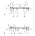
レンズ取付機構4は、図2に具体的に拡大して示すものである。図2において、レンズ取付機構4は、円筒形のレンズ鏡筒3の外周に装着された鏡筒装着部材5と、装置本体2の台座2aに固定されたベース部材6と、ベース部材6に挟まれた状態で回動可能に配置されたリング部材7と、を備える。
【0036】
鏡筒装着部材5は、レンズ鏡筒3が挿通された筒状部5aと、筒状部5aの一端から外径方向に延出する矩形のフランジ部5bと、筒状部5aの他端から周方向で複数点在して外径方向に突出する突部5cと、を備える。この筒状部5aは、レンズ鏡筒3の外周に装着されて固定されており、レンズ鏡筒3と一体化されている。
【0037】
一方、ベース部材6は、中心にレンズ鏡筒3の一部が差し込まれる孔部8を備えている。孔部8は、開口径が筒状部5aの外径より若干大きく形成されている。
【0038】
孔部8を形成するベース部材6の内周面には、筒状部5aから外径方向に突出した鏡筒装着部材5の突部5cもレンズ鏡筒3と共に孔部8へ差し込み可能となるように溝6aが形成されている。溝6aは、レンズ鏡筒3が差し込み可能なように周方向位置を突部5cと合わせて複数設けられており、本実施の形態では、突部5cや溝6aの数は周方向に8箇所である。
【0039】
また、ベース部材6のレンズ鏡筒3の差し込まれる側の開口端面6bは、レンズ鏡筒3を鏡筒装着部材5と伴にベース部材6の孔部8に差し込んだ時に鏡筒装着部材5のフランジ部5bが最終的に当接する部分である。
【0040】
このベース部材6は、ベース本体部6cと、鏡筒装着部材5側の開口端面6bとなる押さえ板6dと、から構成されている。ベース本体部6cには、ベース部材6の押さえ板6dを不図示とした図3に示すようにリング部材7が孔部8と同中心で回動可能なようにリング部材7の外径形状に合わせた掘り込み6eが形成されている。そして、ベース本体部6cの掘り込み6e内にリング部材7を配置した状態で押さえ板6dがその上からリング部材7の取り出しができないようにベース本体部6cにねじ止めされる。これによって、リング部材7は、ベース部材6に中心位置のずれなく周方向に回動可能に挟まれた状態となっている。
【0041】
リング部材7は、図3に示すような環状である。リング部材7の内周は、孔部8と略同径の孔になっている。リング部材7の外周には、一対の耳片7a,7bがベース部材6から突出して設けられている。よって、リング部材7は、耳片7a,7bを作業者が触ることで回動させることができる。
【0042】
またこのリング部材7には、ベース部材6の孔部8を形成する内周に形成された溝6aと同様に突部5cを差し込み可能にする溝6aと同形状の凹部7cが溝6aと同数内周に形成されている。
【0043】
ここで、図3に示す状態を説明すると、図3(a)では、溝6aと凹部7cが周方向で重ねられた位置にあり、レンズ鏡筒3をベース部材6に差し込んだ時に鏡筒装着部材5の突部5cも孔部8に差し込まれていくことが可能となっている。
【0044】
一方、図3(b)では、溝6aに対して凹部7cが周方向で異なる位置にあり、溝6aが破線で示されているようにリング部材7で遮断された状態である。よって、この図3(b)の状態では、突部5cがリング部材7に当接してしまうので、レンズ鏡筒3をベース部材6に差し込むことができない。
【0045】
しかし、一方で、レンズ鏡筒3のベース部材6への差し込み完了後に、リング部材7を図3(a)から図3(b)の状態になるように回動すると、突部5cがリング部材7で係止されるためにベース部材6からレンズ鏡筒3の離脱ができなくなる。即ち、レンズ鏡筒3の装置本体2への取り付けができることになる。
【0046】
ここで、突部5cがリング部材7で係止された時にレンズ鏡筒3が差し込み方向又は反差し込み方向にスライドしてがたつかないようにする必要がある。このため、ベース部材6の開口端面6bに鏡筒装着部材5のフランジ部5bが当接するまでレンズ鏡筒3が差し込まれた状態で突部5cがリング部材7で係止されるように寸法設計がなされている。
【0047】
以上の構成に基づいて、レンズ鏡筒3の装着について説明する。まず、リング部材7の耳片7a,7bを触ってリング部材7を回動してベース部材6の溝6aとリング部材7の凹部7cとを周方向で重ね、レンズ鏡筒3を孔部8に差し込む。すると、鏡筒装着部材5の突部5cがリング部材7に邪魔をされずに孔部8の溝6a及び凹部7cを移動し、フランジ部5bが開口端面6bに当接するまでレンズ鏡筒3を孔部8に差し込むことができる。
【0048】
その後、リング部材7の耳片7a,7bを触ってリング部材7を回動させて凹部7cをベース部材6の溝6aに対して周方向でずらすことで鏡筒装着部材5の突部5cがリング部材7で係止され、鏡筒装着部材5をベース部材6に固定してレンズ鏡筒3を装置本体2に取り付けることができる。
【0049】
また、この動作の逆を行えばレンズ鏡筒3の装置本体2からの離脱が可能である。即ち、鏡筒装着部材5の突部5cがリング部材7で係止してレンズ鏡筒3を装置本体2に取り付けた凹部7cを溝6aに対して周方向でずらした状態からリング部材7を回動させて溝6aと凹部7cとを周方向で重ね、レンズ鏡筒3を引き抜くことでレンズ鏡筒3を装置本体2から離脱することができる。
【0050】
以上のように、本実施の形態では、溝6aと凹部7cとを周方向で重ね、鏡筒装着部材5のフランジ部5bが開口端面6bに当接するまでレンズ鏡筒3をベース部材6の形成する孔部8に差し込み、次にリング部材7を回動して凹部7cを溝6aに対して周方向でずらすことだけでレンズ鏡筒3の取り付けが可能である。
【0051】
よって、レンズ鏡筒3を鏡筒装着部材5の突部5cがベース部材6の孔部8の溝6aに沿って差し込みできれば、重いレンズ鏡筒3の姿勢、位置等を安定させておいてその着脱が可能となる。
【0052】
また、この様にレンズ鏡筒3の姿勢、位置等を安定させておいて差し込みができ、固定を専用工具も必要なくリング部材7の回動だけでワンタッチで着脱が行えるので、作業性が容易となり、作業自体も一人で行うことができる。
【0053】
また、本実施の形態のリング部材7は、次のような特徴も有している。即ち、凹部7cを溝6aと周方向でずらした時のリング部材7を係止した位置をレンズ鏡筒3の差し込み側に折り曲げた付勢手段としての屈曲部7dとしている。
【0054】
屈曲部7dは、平板部分に対して屈曲部7dが図4(b)の矢印で示すようなレンズ鏡筒3の差し込み方向(差し込み奥側)に突き出ており、屈曲部7d自身の弾性で鏡筒装着部材5の突部5cを差し込み方向へ押し付ける付勢を行うため、鏡筒装着部材5はフランジ部5bが開口端面6bに確実に当接した状態に維持される。よって、鏡筒装着部材5をしっかりとベース部材6に固定でき、レンズ鏡筒3が装置本体2に対してがたつくことが防止できる。
【0055】
なお、この屈曲部7dは、溝6aと凹部7cとを周方向で重ねた状態では、図4(a)に示すように溝6aと周方向で異なる位置の隙間にある。
【0056】
また、リング部材7には、回動位置を限定するためにロック機構としてレバー9を一方の耳片7bに取り付けている。レバー9は、先端がベース部材6のベース本体部6cに設けられた穴10に係合するようなバネ性を有するものである。このレバー9に対する穴10の位置は、図2に示すように、溝6aと凹部7cとを周方向で重ねた位置と、溝6aと凹部7cとを周方向でずらした位置と、に2箇所設定される。
【0057】
このレバー9と穴10との係合によってリング部材7の周方向での移動位置をうまくコントロールすることができ、リング部材7の位置を精度よく位置決めすることができる。
【0058】
なお、レバー9以外にもリング部材7とベース部材6とに凹凸の係合機構を所定の箇所に設けることで同様なロック機構を実現してもよい。
【0059】
ここで、このプロジェクタ装置には、不図示であるが、レンズ鏡筒移動機構を搭載している。レンズ鏡筒移動機構は、上下方向及び左右方向に延在するガイドレールに沿ってレンズ鏡筒を移動させる機構で、2つの駆動源がそれぞれのガイドレールに対応するラックを移動させることで、レンズ鏡筒が上下方向又は左右方向にシフト調整される。
【0060】
(第2の実施の形態)
図5〜図7を用いて第2の実施の形態について説明する。なお、プロジェクタ装置全体、及び各部材の形状、材質等は第1の実施の形態と同様であるので、その説明は省略する。
【0061】
本実施の形態では、第1の実施の形態と異なり、リング部材7に屈曲部を形成していない。しかし、リング部材7に重ねて一体化されて配置された付勢手段としてのバネ部材11を備えている。
【0062】
即ち、本実施の形態のレンズ取付機構4は、レンズ鏡筒3の外周に装着された鏡筒装着部材5と、装置本体2の台座2aに固定されたベース部材6と、ベース部材6に挟まれた状態で回動可能に配置されたリング部材7と、リング部材7に重ねて一体化されて重ねられたバネ部材11と、を備える。
【0063】
バネ部材11は、概略図7のような環状形状をしており、突部5cを係止する位置が切り起こされて自身で弾性を有する板バネ部11aとなっている。また、リング部材と同様に鏡筒装着部材5の突部5cを通過させるための凹部11bを有する。
【0064】
バネ部材11の板バネ部11aは、図6(b)の矢印で示すように鏡筒装着部材5の突部5cをレンズ鏡筒3の差し込み方向へ押し付ける付勢を行うため、鏡筒装着部材5はフランジ部5bが開口端面6bに確実に当接した状態に維持される。よって、鏡筒装着部材5をしっかりと固定でき、レンズ鏡筒3が装置本体2に対してがたつくことが防止できる。
【0065】
なお、この板バネ部11aは、溝6aと凹部7cとを周方向で重ねた状態では、図6(a)に示すように溝と周方向で異なる位置にある。また、この状態では、凹部7cにバネ部材11の凹部11bが周方向で重なっている。
【0066】
以上の構成においても、第1の実施の形態と同様の効果を得ることができる。
【0067】
(第3の実施の形態)
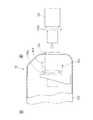
図8〜図11を用いて第3の実施の形態について説明する。なお、プロジェクタ装置全体、及び各部材の形状、材質等は第1の実施の形態と同様であり、レンズ取付機構は第2の実施の形態と同様であるので、その説明は省略する。
【0068】
本実施の形態は、図8に示すように、第2の実施の形態のレンズ取付機構4に対し、上記第1、第2の実施の形態とは異なるロック機構を採用した構成である。
【0069】
ロック機構としては、ベース本体部6cに設けられた位置決め穴12と、リング部材7に設けられたレバー13と、から構成される。
【0070】
位置決め穴12は、ベース本体部6cの表面に形成された楕円形状の穴であり、溝6aと凹部7cとを周方向で重ねた位置(図9(a))と、溝6aと凹部7cとを周方向でずらした位置(図9(b))と、の双方において後述するレバー13を構成するスライド部材15の凸部15aと係合するように2ヶ所形成される。
【0071】
レバー13は、図10に示すように、リング部材7に取り付け固定された固定部材14と、位置決め穴12に係合する凸部15aを有し、凸部15aの位置決め穴12に対する係合を解除可能とするように固定部材14にスライド可能に取り付けられたスライド部材15と、固定部材14とスライド部材15との間に挟まれる板バネ部材16と、凸部15aが位置決め穴12に係合する方向にスライド部材15を付勢する第2付勢手段としてのコイルバネ17と、で構成される。
【0072】
固定部材14は、薄板状であり、取付部14aと本体部14bとつまみ部14cとを有する。固定部材14は、リング部材7の耳片7bに対して取付部14aがビスによって取り付けられ、取付部14aから本体部14bがリング部材7の表面に垂直に延出しリング部材7と平行に折れ曲がったL字状に形成され、本体部14bの取付部14aとは反対側端部に作業者が操作するつまみ部14cが形成される。
【0073】
また、スライド部材15は、固定部材14と略同形状の薄板状であり、凸部15aと本体部15bとつまみ部15cを有し、固定部材14に重ねられている。スライド部材15は、位置決め穴12に係合する凸部15aがL字状の本体部15bの先端に設けられ、本体部15bが固定部材14の本体部14bより相対的に小さく同形状で形成され、本体部15bの凸部15aとは反対側端部に作業者が操作するつまみ部15cが形成される。
【0074】
このスライド部材15には、本体部15bにスライド用孔15d,15eが形成されており、このスライド用孔15d,15eにそれぞれピン18a,18bが差し込まれることでピン18a,18bが固定部材14に固定されている。ピン18a,18bは、スライド部材15のスライド量をピン18aがスライド用孔15d内で移動できる範囲に制限する。
【0075】
板バネ部材16は、固定部材14の本体部14bとスライド部材15の本体部15bとの間に延出方向に反りを有する状態で挟み込まれている。この板バネ部材16が固定部材14とスライド部材15の間に挟み込まれることにより、固定部材14とスライド部材15との間に両者が相反する方向のテンションがかかり、装置作動時の振動でスライド部材15が共振して共鳴することが防止される。また、スライド部材15が固定部材14に引っ掛からずにスムーズにスライドできるという効果も得られる。なお、板バネ部材16を用いることなく、固定部材14又はスライド部材15の一方を板バネ部材16の機能を持たせる形状としてその効果を発揮させることでもよい。
【0076】
一方、コイルバネ17は、固定部材14の本体部14bに設けられスライド用孔15eから突出したフック14dと、スライド部材15の本体部15bに設けられたフック15fと、の間に掛け渡され、凸部15aが位置決め穴12に係合する方向、即ち、凸部15aをベース本体部6c側に押出す方向に付勢する。
【0077】
以上の構成に基づいて、ロック機構の解除動作について説明する。ここでは、図9に示すように溝6aと凹部7cとを周方向で重ねた位置(図9(a))から、溝6aと凹部7cとを周方向でずらした位置(図9(b))にまで、リング部材7を回動させる動作に基づいて説明する。
【0078】
具体的には、図11に示すように、スライド部材15の凸部15aが位置決め穴12に係合している状態(図11(a))から、スライド部材15をコイルバネ17の付勢に抗して図示矢印Fの方向にスライドさせることで凸部15aの位置決め穴12に対する係合を解除してリング部材7を回動可能な状態(図11(b)))にする。
【0079】
この時、スライド部材15をスライドさせる動作は、スライド部材15のつまみ部15cを固定部材14のつまみ部14cに引き寄せることで行うことができる。この引き寄せる作業は、作業者が片手の親指と人差し指等をそれぞれのつまみ部15c,14cにかけて片手で簡単に行うことができる。
【0080】
次に、レバー13を動かしてリング部材7をほんの少し凸部15aが位置決め穴12に差し込まれない位置にまで回動させる。これにより、作業者がスライド部材15をスライドさせる力を緩めたとしても、スライド部材15はコイルバネ17の付勢により凸部15aがベース本体部6cの表面に突き当たった状態となり、リング部材7の回動には影響を与えない。
【0081】
そして、リング部材7の回動は、スライド部材15をスライドさせるか否かにかかわらず、上記の凸部15aがベース本体部6cの表面に突き当たった状態で図9(a)から図9(b)まで行っていけば、所望の位置決め穴12までリング部材7が回動すると、凸部15aがコイルバネ17の付勢によって自動的に位置決め穴12に差し込まれて係合状態となる。
【0082】
このため、作業者としては、スライド部材15のスライド作業とリング部材7の回動作業とを同時に行うことは係合解除するときのほとんどわずかであり、その後はリング部材7の回動作業に専念することで作業が終了するので、作業者のロック機構解除からリング部材7の回動作業までがより単純で簡便なものとなっている。
【0083】
【発明の効果】
以上説明したように本発明では、リング部材を回動してベース部材の溝とリング部材の凹部とを周方向で重ねることで鏡筒装着部材のフランジ部が開口端面に当接するまでレンズ鏡筒を孔部に差し込み、その後リング部材を回動して凹部を溝と周方向でずらすことで突部がリング部材で係止されて鏡筒装着部材を固定することによってレンズ鏡筒を装置本体に取り付けるので、鏡筒装着部材のフランジ部が開口端面に当接するまでレンズ鏡筒をベース部材の孔部に差し込み、次にリング部材を回動することだけでレンズ鏡筒の取り付けが可能である。
【0084】
よって、レンズ鏡筒を鏡筒装着部材の突部がベース部材の孔部の溝に嵌るように差し込みできれば、重いレンズ鏡筒の姿勢、位置等を安定させておいて着脱が可能となる。
【0085】
また、この様にレンズ鏡筒の姿勢、位置等を安定させておいて差し込みができ、固定を専用工具も必要なくリング部材の回動だけでワンタッチで着脱が行えるので、作業性が容易となり、作業自体も一人で行うことができる。
【図面の簡単な説明】
【図1】第1の実施の形態に係るプロジェクタ装置を示す図である。
【図2】第1の実施の形態に係るレンズ取付機構を示す図である。
【図3】第1の実施の形態に係るレンズ取付機構の要部を示す図である。
【図4】第1の実施の形態に係るレンズ取付機構の要部を示す図である。
【図5】第2の実施の形態に係るレンズ取付機構を示す図である。
【図6】第2の実施の形態に係るレンズ取付機構の要部を示す図である。
【図7】第2の実施の形態に係るバネ部材を示す図である。
【図8】第3の実施の形態に係るレンズ取付機構を示す図である。
【図9】第3の実施の形態に係るレンズ取付機構の要部を示す図である。
【図10】第3の実施の形態に係るレンズ取付機構のレバーを示す図である。
【図11】第3の実施の形態に係るレンズ取付機構のレバーを示す図である。
【図12】従来技術のプロジェクタ装置を示す図である。
【符号の説明】
1 プロジェクタ装置
2 装置本体
2a 台座
3 レンズ鏡筒
4 レンズ取付機構
5 鏡筒装着部材
5a 筒状部
5b フランジ部
5c 突部
6 ベース部材
6a 溝
6b 開口端面
6c ベース本体部
6d 押さえ板
6e 掘り込み
7 リング部材
7c 凹部
7d 屈曲部
7a,7b 耳片
8 孔部
9 レバー
10 穴
11 バネ部材
11a 板バネ部
11b 凹部
12 位置決め穴
13 レバー
14d フック
14 固定部材
14a 取付部
14b 本体部
14c つまみ部
15 スライド部材
15a 凸部
15b 本体部
15c つまみ部
15d,15e スライド用孔
15f フック
16 板バネ部材
17 コイルバネ
18a,18b ピン[0001]
BACKGROUND OF THE INVENTION
The present invention relates to a projector apparatus used in a projection type image display apparatus that projects and displays a projected image on a screen, and more particularly to a lens mounting mechanism for attaching and detaching a lens barrel.
[0002]
[Prior art]
A configuration example of a conventional projector apparatus will be described. The projector device has a light source such as a metal hydride lamp, a dichroic mirror for separation, a reflection mirror, a liquid crystal panel, a dichroic mirror for photosynthesis, an optical path adjustment mechanism composed of a pair of liquid prisms, and a projection lens mounted in the housing. It has been.
[0003]
The light emitted from the light source is split into three primary colors of red, blue, and green by a separating dichroic mirror. The transmittance of the dispersed light is modulated in accordance with the image information of each color component in the liquid crystal panel on each optical path. The modulated light is synthesized by a dichroic mirror for photosynthesis. Then, after the optical path is adjusted by the optical path modulation mechanism, the combined light is enlarged and projected on the screen by the projection lens.
[0004]
The projector device that performs the enlarged projection of the image as described above is used in a place where conditions such as a distance to the screen and a size of the screen are different.
[0005]
For this reason, in order to improve the image accuracy, the lenses of the projector apparatus are exchanged to meet these various conditions.
[0006]
In addition, by making it possible to replace the lens, it is possible to use it with a replacement lens for repair, etc., or to replace only the lens part when it is necessary to replace the lens parts. It will also improve.
[0007]
Here, a method for exchanging lenses in a conventional projector apparatus will be described. FIG. 12 is a schematic view of a projector apparatus in which a conventional lens replacement portion is partially cut away.
[0008]
In FIG. 12, the
[0009]
As shown in FIG. 12, the
[0010]
[Problems to be solved by the invention]
However, in the above-described prior art, when the projector device is particularly large, the lens barrel itself is very heavy, and it may be difficult to handle due to its weight. It is difficult to attach and detach the heavy lens barrel with its posture and position stabilized.
[0011]
In particular, because the lens barrel is large and the space around it is limited, it is difficult for the operator to put in a hand to lift the lens barrel. It was a thing.
[0012]
Also, the work itself has to be performed by a plurality of persons including a person who lifts the lens barrel and a person who performs screwing with a dedicated tool, which is very troublesome.
[0013]
The present invention has been made in view of the above prior art, and an object of the present invention is to provide a lens mounting mechanism and a projector apparatus that can easily attach and detach a lens barrel.
[0014]
[Means for Solving the Problems]
In order to achieve the above object, in the lens mounting mechanism of the present invention, the lens is mounted on the outer periphery of the lens barrel arranged inside, and extends from the cylindrical portion and one end of the cylindrical portion in the outer diameter direction. A lens barrel mounting member having a protruding flange portion, and a plurality of protrusions that are scattered in the circumferential direction from the other end of the cylindrical portion and project in the outer diameter direction, a base body portion, and a pressing plate A hole portion that is fixed to the apparatus main body to which the lens barrel is attached, is formed through the base main body portion and the pressing plate, and the cylindrical portion is inserted from the other end side together with the lens barrel. It was formed along the insertion direction of the cylindrical part on the peripheral surfaceWhile restricting the posture of the lens barrel mounting member from changing in the circumferential direction of the hole, Make the protrusions pluggableApproximately the same shape as the protrusion. A base member having a groove and an opening end surface of the hole portion, which is provided in the pressing plate and contacts the flange portion, and is rotatable between the base body portion and the pressing plate. It is arranged and enables the projection to be inserted into the inner periphery in the same manner as the groove.Same shape as the groove A ring member having a recess, and rotating the ring member to overlap the groove of the base member and the recess of the ring member in the circumferential direction, and the hole on the holding plate side of the hole The projecting part is inserted into a groove formed in the part, the other end side of the cylindrical part is inserted from the opening end surface into the hole on the holding plate side, and the flange part of the lens barrel mounting member is the opening end surface The other end of the cylindrical portion is extended to the hole on the base body portion side while the protrusion is inserted along the groove formed in the recess of the ring member and the hole on the base body portion side until it comes into contact with After the insertion, the ring member is rotated to shift the concave portion in the circumferential direction with respect to the groove, so that the protrusion inserted into the groove formed in the hole on the base body side is the ring member. Locked to fix the lens barrel mounting member Wherein the attachment of the lens barrel in the apparatus main body by the.
[0015]
Therefore, the lens barrel can be attached only by inserting the lens barrel into the hole of the base member until the flange portion of the barrel mounting member comes into contact with the opening end surface and then rotating the ring member.
[0016]
Therefore, if the projection of the lens barrel mounting member can be inserted along the groove of the hole of the base member, the lens barrel can be attached and detached while stabilizing the posture, position, etc. of the heavy lens barrel.
[0017]
In addition, it is possible to insert the lens barrel with its posture, position, etc. stabilized in this way, and it is easy to work because it can be attached and detached with just one turn of the ring member without the need for dedicated tools. The work itself can be done alone.
[0018]
It is preferable that an urging unit is provided to urge the protrusion in the insertion direction of the lens barrel when the protrusion is locked by the ring member.
[0019]
Thereby, the lens barrel mounting member can be firmly fixed, and the lens barrel can be prevented from rattling.
[0020]
It is preferable that the urging means is a bent portion where the position where the protrusion of the ring member is locked is bent toward the insertion side of the lens barrel.
[0021]
Thereby, a protrusion can be pressed and urged | biased by the bending part of a ring member.
[0022]
It is preferable that the urging means is a spring member which is arranged on the ring member on the insertion side of the lens barrel so as to be a leaf spring at a position where the protrusion is locked.
[0023]
Thereby, a protrusion can be pressed with a leaf | plate spring and can be urged | biased.
[0024]
It is preferable that a lock mechanism for positioning the ring member at a position where the groove and the concave portion are overlapped in the circumferential direction and a position where the groove and the concave portion are shifted in the circumferential direction is provided.
[0025]
Thereby, the positioning when the ring member is moved in the circumferential direction can be accurately performed.
[0026]
The lock mechanism includes a positioning hole provided in a base member, a fixing member attached to and fixed to the ring member, and a convex portion that engages with the positioning hole, and the convex portion engages with the positioning hole. And a second urging means for urging the slide member in a direction in which the convex portion engages with the positioning hole. The slide member is slid against the urging force of the second urging means to release the engagement of the convex portion with the positioning hole, thereby enabling the ring member to rotate and the positioning. The ring member is positioned at a position where the groove and the concave portion are overlapped in the circumferential direction by engaging the convex portion with the hole and a position where the groove and the concave portion are shifted in the circumferential direction. Suitable A.
[0027]
As a result, by sliding the slide member, it is possible to release the engagement between the positioning portion and the protruding portion that is positioned by removing the protruding portion from the positioning hole, and a force must be applied to the sliding member in the sliding state. For example, since the slide member naturally slides in the engagement direction by the urging of the second urging means, the operator's work becomes very simple.
[0028]
According to another aspect of the invention, there is provided a projector device comprising: the lens mounting mechanism described above; a lens barrel that is detachable by the lens mounting mechanism; and a device main body to which the lens barrel is mounted. .
[0029]
DETAILED DESCRIPTION OF THE INVENTION
(First embodiment)
The first embodiment will be described with reference to FIGS.
[0030]
FIG. 1 is a diagram showing a projector apparatus 1 according to the first embodiment. A projector apparatus 1 shown in FIG. 1 has a
[0031]
The projector apparatus 1 includes an apparatus main body 2, a
[0032]
Although not shown, the apparatus main body 2 includes a light source, various mirrors, an image display panel, a lens barrel moving mechanism, and the like.
[0033]
The
[0034]
In the projector device 1, the light emitted from the light source is reflected by various mirrors and turned back, and the transmittance is modulated according to image information on the midway image display panel, passes through the
[0035]
The
[0036]
The lens
[0037]
On the other hand, the
[0038]
On the inner peripheral surface of the
[0039]
Further, the opening
[0040]
The
[0041]
The
[0042]
In addition, the
[0043]
Here, the state shown in FIG. 3 will be described. In FIG. 3A, the
[0044]
On the other hand, in FIG.3 (b), the recessed
[0045]
However, on the other hand, when the
[0046]
Here, when the
[0047]
Based on the above configuration, the mounting of the
[0048]
Thereafter, by touching the
[0049]
Further, if this operation is reversed, the
[0050]
As described above, in the present embodiment, the
[0051]
Therefore, if the
[0052]
In addition, the
[0053]
Moreover, the
[0054]
The
[0055]
In addition, this bending
[0056]
The
[0057]
The engagement position of the
[0058]
In addition to the
[0059]
Here, the projector device is equipped with a lens barrel moving mechanism (not shown). The lens barrel moving mechanism is a mechanism for moving the lens barrel along guide rails extending in the vertical direction and the horizontal direction, and the two drive sources move the racks corresponding to the respective guide rails, thereby moving the lens. The lens barrel is shifted and adjusted in the vertical direction or the horizontal direction.
[0060]
(Second Embodiment)
A second embodiment will be described with reference to FIGS. Note that the overall projector device and the shape, material, and the like of each member are the same as those in the first embodiment, and thus the description thereof is omitted.
[0061]
In the present embodiment, unlike the first embodiment, a bent portion is not formed in the
[0062]
That is, the
[0063]
The
[0064]
The
[0065]
In addition, this leaf |
[0066]
Also in the above configuration, the same effect as that of the first embodiment can be obtained.
[0067]
(Third embodiment)
A third embodiment will be described with reference to FIGS. Note that the overall projector device and the shape, material, and the like of each member are the same as in the first embodiment, and the lens mounting mechanism is the same as in the second embodiment, and thus the description thereof is omitted.
[0068]
In the present embodiment, as shown in FIG. 8, a lock mechanism different from the first and second embodiments is employed for the
[0069]
The locking mechanism includes a
[0070]
The
[0071]
As shown in FIG. 10, the
[0072]
The fixing
[0073]
The
[0074]
The
[0075]
The
[0076]
On the other hand, the
[0077]
Based on the above configuration, the unlocking operation of the lock mechanism will be described. Here, as shown in FIG. 9, the
[0078]
Specifically, as shown in FIG. 11, the
[0079]
At this time, the operation of sliding the
[0080]
Next, the
[0081]
Then, the rotation of the
[0082]
For this reason, as an operator, performing the sliding operation of the sliding
[0083]
【The invention's effect】
As described above, in the present invention, the lens barrel is rotated until the flange portion of the lens barrel mounting member comes into contact with the opening end surface by rotating the ring member and overlapping the groove of the base member and the concave portion of the ring member in the circumferential direction. Is inserted into the hole, and then the ring member is rotated to shift the recess in the circumferential direction with the groove, so that the projection is locked by the ring member and the lens barrel mounting member is fixed, thereby fixing the lens barrel to the apparatus main body. Since the lens barrel is attached, the lens barrel can be attached only by inserting the lens barrel into the hole of the base member until the flange portion of the barrel mounting member comes into contact with the opening end surface and then rotating the ring member.
[0084]
Therefore, if the lens barrel can be inserted so that the projection of the lens barrel mounting member fits into the groove of the hole of the base member, the heavy lens barrel can be attached and detached while stabilizing the posture, position, and the like.
[0085]
In addition, it is possible to insert the lens barrel with its posture, position, etc. stabilized in this way, and it is easy to work because it can be attached and detached with just one turn of the ring member without the need for dedicated tools. The work itself can be done alone.
[Brief description of the drawings]
FIG. 1 is a diagram showing a projector apparatus according to a first embodiment.
FIG. 2 is a diagram showing a lens mounting mechanism according to the first embodiment.
FIG. 3 is a diagram showing a main part of the lens mounting mechanism according to the first embodiment.
FIG. 4 is a diagram illustrating a main part of the lens mounting mechanism according to the first embodiment.
FIG. 5 is a diagram showing a lens mounting mechanism according to a second embodiment.
FIG. 6 is a diagram showing a main part of a lens mounting mechanism according to a second embodiment.
FIG. 7 is a view showing a spring member according to a second embodiment.
FIG. 8 is a diagram showing a lens mounting mechanism according to a third embodiment.
FIG. 9 is a diagram illustrating a main part of a lens mounting mechanism according to a third embodiment.
FIG. 10 is a diagram showing a lever of a lens mounting mechanism according to a third embodiment.
FIG. 11 is a diagram illustrating a lever of a lens mounting mechanism according to a third embodiment.
FIG. 12 is a diagram showing a projector device according to the prior art.
[Explanation of symbols]
1 Projector device
2 Main unit
2a pedestal
3 Lens barrel
4 Lens mounting mechanism
5 Lens mounting member
5a Tubular part
5b Flange part
5c protrusion
6 Base member
6a Groove
6b Open end face
6c Base body
6d holding plate
6e digging
7 Ring member
7c recess
7d bent part
7a, 7b Ear piece
8 holes
9 Lever
10 holes
11 Spring member
11a leaf spring
11b recess
12 Positioning hole
13 Lever
14d hook
14 Fixing member
14a Mounting part
14b Body
14c Knob part
15 Slide member
15a Convex
15b body part
15c Knob part
15d, 15e Slide holes
15f hook
16 Leaf spring member
17 Coil spring
18a, 18b pins
Claims (7)
Translated fromJapanese筒状部、
該筒状部の一端から外径方向に延出するフランジ部、及び
前記筒状部の他端から周方向で複数点在して外径方向に突出する突部、を有する鏡筒装着部材と、
ベース本体部及び押さえ板から構成されるとともにレンズ鏡筒の取り付けられる装置本体に固定され、
前記ベース本体部及び前記押さえ板を貫いて形成されてレンズ鏡筒と共に前記筒状部が前記他端側から差し込まれる孔部、
該孔部の内周面に前記筒状部の差し込み方向に沿って形成された、前記鏡筒装着部材の姿勢が前記孔部の周方向に変化しようとするのを規制せしめつつ前記突部を差し込み可能にする前記突部と略同形状の溝、及び
前記押さえ板に設けられ前記フランジ部を当接させる前記孔部の開口端面、
を有するベース部材と、
前記ベース本体部と前記押さえ板との間に挟まれた状態で回動可能に配置され、
内周に前記溝と同様に前記突部を差し込み可能にする前記溝と同形状の凹部、を有するリング部材と、
を備え、
前記リング部材を回動して前記ベース部材の前記溝と前記リング部材の前記凹部とを周方向で重ね、前記孔部のうち前記押さえ板側の孔部に形成された溝に前記突部を差し込んで、前記筒状部の他端側を前記開口端面から前記押さえ板側の孔部に差し込み、前記鏡筒装着部材の前記フランジ部が前記開口端面に当接するまで前記突部を前記リング部材の凹部及び前記ベース本体部側の孔部に形成された溝に沿って差し込みながら前記筒状部の他端側を前記ベース本体部側の孔部まで差し込み、
その後、前記リング部材を回動して前記凹部を前記溝と周方向でずらすことで、前記ベース本体部側の孔部に形成された溝まで差し込まれた前記突部が前記リング部材で係止されて前記鏡筒装着部材を固定することによってレンズ鏡筒を装置本体に取り付けることを特徴とするレンズ取付機構。The lens is mounted on the outer periphery of the lens barrel placed inside,
Cylindrical part,
A lens barrel mounting member having a flange portion extending in the outer diameter direction from one end of the cylindrical portion, and a plurality of protrusions that are scattered in the circumferential direction from the other end of the cylindrical portion and project in the outer diameter direction; ,
It is composed of a base body part and a holding plate and is fixed to the apparatus body to which the lens barrel is attached,
A hole that is formed through the base body and the pressing plate and into which the cylindrical portion is inserted together with the lens barrel from the other end side;
The protrusion is formed on the inner peripheral surface of thehole portion along the insertion direction of thecylindrical portion while restricting the posture of the lens barrel mounting member from changing in the circumferential direction of the hole portion.A groovehaving substantially the same shape as the protruding portion that can be inserted, and an opening end surface of the hole portion that is provided on the pressing plate and contacts the flange portion;
A base member having
It is arranged to be rotatable in a state of being sandwiched between the base body part and the pressing plate,
A ring member havinga recess having thesame shape as the groove, which allows the protrusion to be inserted into the inner periphery in the same manner as the groove;
With
The ring member is rotated to overlap the groove of the base member and the recess of the ring member in the circumferential direction, and the protrusion is placed in a groove formed in the hole on the holding plate side of the hole. Insert the other end side of the cylindrical part from the opening end surface into the hole on the holding plate side, and insert the protrusion into the ring member until the flange portion of the lens barrel mounting member comes into contact with the opening end surface The other end side of the cylindrical part is inserted to the hole part on the base body part side while being inserted along the groove formed in the recess part and the hole part on the base body part side,
Thereafter, by rotating the ring member and shifting the concave portion in the circumferential direction with respect to the groove, the protrusion inserted into the groove formed in the hole on the base body side is locked by the ring member. And a lens mounting mechanism for mounting the lens barrel to the apparatus main body by fixing the lens barrel mounting member.
ベース部材に設けられた位置決め穴と、
前記リング部材に取り付け固定された固定部材と、
前記位置決め穴に係合する凸部を有し、前記凸部の前記位置決め穴に対する係合を解除可能とするように前記固定部材にスライド可能に取り付けられたスライド部材と、
前記凸部が前記位置決め穴に係合する方向に前記スライド部材を付勢する第2付勢手段と、
で構成され、
前記スライド部材を前記第2付勢手段の付勢に抗してスライドさせることで前記凸部の前記位置決め穴に対する係合を解除して前記リング部材を回動可能とすると共に、前記位置決め穴に前記凸部を係合させることで前記溝と前記凹部とを周方向で重ねた位置と、前記溝と前記凹部とを周方向でずらした位置と、に前記リング部材を位置決めすることを特徴とする請求項5に記載のレンズ取付機構。The locking mechanism is
Positioning holes provided in the base member;
A fixing member attached and fixed to the ring member;
A slide member that has a convex portion that engages with the positioning hole, and is slidably attached to the fixing member so that the engagement of the convex portion with respect to the positioning hole can be released;
Second urging means for urging the slide member in a direction in which the convex portion engages with the positioning hole;
Consisting of
By sliding the slide member against the urging force of the second urging means, the engagement of the convex portion with the positioning hole is released, and the ring member can be rotated, and the positioning hole The ring member is positioned at a position where the groove and the concave portion are overlapped in the circumferential direction by engaging the convex portion, and a position where the groove and the concave portion are shifted in the circumferential direction. The lens mounting mechanism according to claim 5.
該レンズ取付機構によって着脱自在となるレンズ鏡筒と、
該レンズ鏡筒が取り付けられる装置本体と、
を備えたことを特徴とするプロジェクタ装置。The lens mounting mechanism according to any one of claims 1 to 6,
A lens barrel detachable by the lens mounting mechanism;
An apparatus main body to which the lens barrel is attached;
A projector apparatus comprising:
Priority Applications (5)
| Application Number | Priority Date | Filing Date | Title |
|---|---|---|---|
| JP2002318882AJP4152168B2 (en) | 2002-08-12 | 2002-10-31 | Lens mounting mechanism and projector device |
| US10/637,582US6778340B2 (en) | 2002-08-12 | 2003-08-11 | Lens mounting mechanism and projector apparatus |
| DE10337070ADE10337070B4 (en) | 2002-08-12 | 2003-08-12 | Lens capture mechanism and projection device |
| CNB031540465ACN100368845C (en) | 2002-08-12 | 2003-08-12 | Lens mounting mechanism and projector |
| GB0318835AGB2393524B (en) | 2002-08-12 | 2003-08-12 | Lens barrel mounting mechanism for projector |
Applications Claiming Priority (2)
| Application Number | Priority Date | Filing Date | Title |
|---|---|---|---|
| JP2002234546 | 2002-08-12 | ||
| JP2002318882AJP4152168B2 (en) | 2002-08-12 | 2002-10-31 | Lens mounting mechanism and projector device |
Publications (2)
| Publication Number | Publication Date |
|---|---|
| JP2004133358A JP2004133358A (en) | 2004-04-30 |
| JP4152168B2true JP4152168B2 (en) | 2008-09-17 |
Family
ID=28043877
Family Applications (1)
| Application Number | Title | Priority Date | Filing Date |
|---|---|---|---|
| JP2002318882AExpired - LifetimeJP4152168B2 (en) | 2002-08-12 | 2002-10-31 | Lens mounting mechanism and projector device |
Country Status (5)
| Country | Link |
|---|---|
| US (1) | US6778340B2 (en) |
| JP (1) | JP4152168B2 (en) |
| CN (1) | CN100368845C (en) |
| DE (1) | DE10337070B4 (en) |
| GB (1) | GB2393524B (en) |
Families Citing this family (21)
| Publication number | Priority date | Publication date | Assignee | Title |
|---|---|---|---|---|
| KR200294451Y1 (en)* | 2002-07-26 | 2002-11-13 | 삼성전자 주식회사 | project-lens apparatus for projector |
| US20100208484A1 (en)* | 2006-07-13 | 2010-08-19 | Lawrence Andrew Hoffman | Tribar lighting |
| JP4502988B2 (en)* | 2006-08-31 | 2010-07-14 | 三洋電機株式会社 | Projection lens removing device and projection-type image display device using the same |
| JP5086214B2 (en)* | 2008-09-19 | 2012-11-28 | 株式会社日立製作所 | Lens mounting mechanism and projector apparatus having lens mounting mechanism |
| JP5100590B2 (en)* | 2008-09-25 | 2012-12-19 | 株式会社コシナ | Interchangeable lens attaching / detaching device for optical equipment |
| JP5782526B2 (en)* | 2011-11-11 | 2015-09-24 | 日立マクセル株式会社 | Projection display device |
| WO2014020987A1 (en) | 2012-07-31 | 2014-02-06 | ソニー株式会社 | Lens attachment mechanism, lens attachment method and imaging device |
| US9154755B2 (en)* | 2012-09-28 | 2015-10-06 | Seiko Epson Corporation | Projector with a lens shift mechanism configured to move a projection lens |
| CN103217770B (en)* | 2013-04-18 | 2015-06-10 | 苏州佳世达光电有限公司 | Lens fixing module and projector using same |
| CN103383517B (en)* | 2013-08-12 | 2015-04-22 | 深圳市帅映科技有限公司 | Fixing and replacing device for projector lens |
| CN103685889B (en)* | 2013-12-02 | 2016-08-24 | 京东方科技集团股份有限公司 | A kind of camera assistive device installing plate and electronic equipment |
| CN106716211A (en)* | 2014-09-25 | 2017-05-24 | 日本电产科宝株式会社 | Imaging device, optical device, electronic device, vehicle, and production method for imaging device |
| US10288985B2 (en)* | 2014-09-25 | 2019-05-14 | Nidec Copal Corporation | Imaging device, optical device, electronic device, vehicle, and production method for imaging device |
| WO2016065518A1 (en) | 2014-10-27 | 2016-05-06 | 深圳市大疆创新科技有限公司 | Lens limiting assembly, camera body, and camera module |
| CN112650006A (en)* | 2014-10-27 | 2021-04-13 | 深圳市大疆创新科技有限公司 | Lens limiting assembly, camera body and camera |
| CN105518527B (en)* | 2014-10-27 | 2020-12-15 | 深圳市大疆创新科技有限公司 | Lens limit assembly, camera body and camera |
| CN105700275B (en)* | 2014-11-24 | 2017-06-27 | 鸿富锦精密工业(武汉)有限公司 | projector |
| DE112016004972B4 (en) | 2015-10-30 | 2022-11-17 | Canon Kabushiki Kaisha | ELECTRONIC DEVICE |
| GB2561103A (en) | 2015-10-30 | 2018-10-03 | Canon Kk | Electronic apparatus |
| CN111352286B (en)* | 2020-02-14 | 2021-05-04 | 梁燕玲 | transfer device |
| CN111308839B (en)* | 2020-03-16 | 2021-10-12 | 宿州青智网络科技有限公司 | Short-focus lens for projector |
Family Cites Families (15)
| Publication number | Priority date | Publication date | Assignee | Title |
|---|---|---|---|---|
| US4302077A (en) | 1978-09-29 | 1981-11-24 | Canon Kabushiki Kaisha | Bayonet device for lens barrel |
| JPH0419895Y2 (en)* | 1986-02-20 | 1992-05-07 | ||
| JPH0638537Y2 (en)* | 1988-10-06 | 1994-10-05 | パイオニア株式会社 | Focusing device for projection TV |
| JPH02104339U (en)* | 1989-02-03 | 1990-08-20 | ||
| JPH0622806Y2 (en)* | 1989-09-27 | 1994-06-15 | パイオニア株式会社 | Lens frame |
| JP3189295B2 (en)* | 1991-04-25 | 2001-07-16 | ソニー株式会社 | Lens mounting device using a tightening ring |
| JPH05181187A (en)* | 1991-11-29 | 1993-07-23 | Nikon Corp | Lens attachment / detachment device |
| FR2686709B1 (en)* | 1992-01-24 | 1994-03-18 | Sextant Avionique | FIXING AND CONNECTING DEVICE, IN PARTICULAR OF A LIGHT ENHANCER ASSEMBLY ON AN IMAGE GENERATOR OF A PILOT HELMET VIEWFINDER. |
| JPH09159893A (en)* | 1995-12-01 | 1997-06-20 | Olympus Optical Co Ltd | Ocular fixing mechanism |
| US5684644A (en)* | 1996-05-03 | 1997-11-04 | Emerging Technologies, Inc. | Variable-length line projecting optics |
| JP3199048B2 (en)* | 1999-01-21 | 2001-08-13 | セイコーエプソン株式会社 | projector |
| JP3447659B2 (en)* | 2000-03-01 | 2003-09-16 | Necビューテクノロジー株式会社 | Projector device |
| JP2001264611A (en)* | 2000-03-16 | 2001-09-26 | Nikon Corp | Head for lens barrel |
| BE1013550A3 (en)* | 2000-06-09 | 2002-03-05 | Barco Nv | Objective confirmation. |
| CN2490593Y (en)* | 2001-08-08 | 2002-05-08 | 力捷电脑股份有限公司 | Holding structure for optical lens |
- 2002
- 2002-10-31JPJP2002318882Apatent/JP4152168B2/ennot_activeExpired - Lifetime
- 2003
- 2003-08-11USUS10/637,582patent/US6778340B2/ennot_activeExpired - Lifetime
- 2003-08-12CNCNB031540465Apatent/CN100368845C/ennot_activeExpired - Lifetime
- 2003-08-12GBGB0318835Apatent/GB2393524B/ennot_activeExpired - Lifetime
- 2003-08-12DEDE10337070Apatent/DE10337070B4/ennot_activeExpired - Lifetime
Also Published As
| Publication number | Publication date |
|---|---|
| US6778340B2 (en) | 2004-08-17 |
| DE10337070B4 (en) | 2012-12-20 |
| GB2393524A (en) | 2004-03-31 |
| GB0318835D0 (en) | 2003-09-10 |
| CN100368845C (en) | 2008-02-13 |
| US20040027692A1 (en) | 2004-02-12 |
| JP2004133358A (en) | 2004-04-30 |
| GB2393524B (en) | 2005-10-26 |
| DE10337070A1 (en) | 2004-02-26 |
| CN1484058A (en) | 2004-03-24 |
Similar Documents
| Publication | Publication Date | Title |
|---|---|---|
| JP4152168B2 (en) | Lens mounting mechanism and projector device | |
| TWI464519B (en) | Projection image display device | |
| JP6191111B2 (en) | projector | |
| JP2010204339A (en) | Projector | |
| JP6500252B2 (en) | Lens barrel | |
| JP2014071195A5 (en) | ||
| JP4024280B1 (en) | Projection display device | |
| JP2017142281A (en) | Projection optical device and projector | |
| CN102253580B (en) | Projector | |
| JP2017030428A (en) | Vehicle projector and vehicle | |
| JP6187638B2 (en) | projector | |
| JP4109999B2 (en) | Projection lens shift device | |
| JP2010066419A (en) | Electronic equipment with opening/closing door | |
| JP6442935B2 (en) | projector | |
| JP4121547B2 (en) | Projection display device | |
| JP4260213B2 (en) | Projection display device | |
| JP5958246B2 (en) | projector | |
| JP5206345B2 (en) | projector | |
| JP6576221B2 (en) | Finder device and imaging device | |
| CN107664902B (en) | Projector with a light source | |
| JP4245640B2 (en) | Projection display device | |
| JP2010217255A (en) | Projector | |
| JP2009169088A (en) | Attaching mechanism for filter device | |
| JP2014228618A (en) | Projector | |
| JP2014235393A (en) | Projector |
Legal Events
| Date | Code | Title | Description |
|---|---|---|---|
| A621 | Written request for application examination | Free format text:JAPANESE INTERMEDIATE CODE: A621 Effective date:20050715 | |
| A977 | Report on retrieval | Free format text:JAPANESE INTERMEDIATE CODE: A971007 Effective date:20070920 | |
| A131 | Notification of reasons for refusal | Free format text:JAPANESE INTERMEDIATE CODE: A131 Effective date:20071002 | |
| A521 | Request for written amendment filed | Free format text:JAPANESE INTERMEDIATE CODE: A523 Effective date:20071203 | |
| A131 | Notification of reasons for refusal | Free format text:JAPANESE INTERMEDIATE CODE: A131 Effective date:20080129 | |
| A521 | Request for written amendment filed | Free format text:JAPANESE INTERMEDIATE CODE: A523 Effective date:20080331 | |
| TRDD | Decision of grant or rejection written | ||
| A01 | Written decision to grant a patent or to grant a registration (utility model) | Free format text:JAPANESE INTERMEDIATE CODE: A01 Effective date:20080617 | |
| A01 | Written decision to grant a patent or to grant a registration (utility model) | Free format text:JAPANESE INTERMEDIATE CODE: A01 | |
| A61 | First payment of annual fees (during grant procedure) | Free format text:JAPANESE INTERMEDIATE CODE: A61 Effective date:20080701 | |
| R150 | Certificate of patent or registration of utility model | Ref document number:4152168 Country of ref document:JP Free format text:JAPANESE INTERMEDIATE CODE: R150 Free format text:JAPANESE INTERMEDIATE CODE: R150 | |
| FPAY | Renewal fee payment (event date is renewal date of database) | Free format text:PAYMENT UNTIL: 20110711 Year of fee payment:3 | |
| FPAY | Renewal fee payment (event date is renewal date of database) | Free format text:PAYMENT UNTIL: 20110711 Year of fee payment:3 | |
| FPAY | Renewal fee payment (event date is renewal date of database) | Free format text:PAYMENT UNTIL: 20120711 Year of fee payment:4 | |
| R250 | Receipt of annual fees | Free format text:JAPANESE INTERMEDIATE CODE: R250 | |
| FPAY | Renewal fee payment (event date is renewal date of database) | Free format text:PAYMENT UNTIL: 20120711 Year of fee payment:4 | |
| FPAY | Renewal fee payment (event date is renewal date of database) | Free format text:PAYMENT UNTIL: 20130711 Year of fee payment:5 | |
| R250 | Receipt of annual fees | Free format text:JAPANESE INTERMEDIATE CODE: R250 | |
| R250 | Receipt of annual fees | Free format text:JAPANESE INTERMEDIATE CODE: R250 | |
| R250 | Receipt of annual fees | Free format text:JAPANESE INTERMEDIATE CODE: R250 | |
| R250 | Receipt of annual fees | Free format text:JAPANESE INTERMEDIATE CODE: R250 | |
| R250 | Receipt of annual fees | Free format text:JAPANESE INTERMEDIATE CODE: R250 | |
| R250 | Receipt of annual fees | Free format text:JAPANESE INTERMEDIATE CODE: R250 | |
| R250 | Receipt of annual fees | Free format text:JAPANESE INTERMEDIATE CODE: R250 | |
| R250 | Receipt of annual fees | Free format text:JAPANESE INTERMEDIATE CODE: R250 | |
| R250 | Receipt of annual fees | Free format text:JAPANESE INTERMEDIATE CODE: R250 | |
| R250 | Receipt of annual fees | Free format text:JAPANESE INTERMEDIATE CODE: R250 | |
| R250 | Receipt of annual fees | Free format text:JAPANESE INTERMEDIATE CODE: R250 | |
| EXPY | Cancellation because of completion of term |