JP4148705B2 - Analysis equipment - Google Patents
Analysis equipmentDownload PDFInfo
- Publication number
- JP4148705B2 JP4148705B2JP2002177828AJP2002177828AJP4148705B2JP 4148705 B2JP4148705 B2JP 4148705B2JP 2002177828 AJP2002177828 AJP 2002177828AJP 2002177828 AJP2002177828 AJP 2002177828AJP 4148705 B2JP4148705 B2JP 4148705B2
- Authority
- JP
- Japan
- Prior art keywords
- analysis
- changeover switch
- circuit
- state
- laser
- Prior art date
- Legal status (The legal status is an assumption and is not a legal conclusion. Google has not performed a legal analysis and makes no representation as to the accuracy of the status listed.)
- Expired - Lifetime
Links
Images


Classifications
- G—PHYSICS
- G01—MEASURING; TESTING
- G01N—INVESTIGATING OR ANALYSING MATERIALS BY DETERMINING THEIR CHEMICAL OR PHYSICAL PROPERTIES
- G01N35/00—Automatic analysis not limited to methods or materials provided for in any single one of groups G01N1/00 - G01N33/00; Handling materials therefor
- G01N35/00029—Automatic analysis not limited to methods or materials provided for in any single one of groups G01N1/00 - G01N33/00; Handling materials therefor provided with flat sample substrates, e.g. slides
- G01N35/00069—Automatic analysis not limited to methods or materials provided for in any single one of groups G01N1/00 - G01N33/00; Handling materials therefor provided with flat sample substrates, e.g. slides whereby the sample substrate is of the bio-disk type, i.e. having the format of an optical disk
Landscapes
- General Health & Medical Sciences (AREA)
- General Physics & Mathematics (AREA)
- Life Sciences & Earth Sciences (AREA)
- Chemical & Material Sciences (AREA)
- Analytical Chemistry (AREA)
- Biochemistry (AREA)
- Immunology (AREA)
- Physics & Mathematics (AREA)
- Health & Medical Sciences (AREA)
- Pathology (AREA)
- Investigating Or Analysing Materials By Optical Means (AREA)
- Optical Recording Or Reproduction (AREA)
- Automatic Analysis And Handling Materials Therefor (AREA)
- Investigating Or Analysing Biological Materials (AREA)
Description
Translated fromJapanese【0001】
【発明の属する技術分野】
本発明は、血液などの分析対象を分析用の光ディスクにセットし、この分析対象をトレースして映像として捉えようする分析装置に関する。
【0002】
【従来の技術】
特表平10−504397号公報などにあるように、光ディスクの再生機能を用いてディスク上のある部分に試験しようとする分析対象を設けて、トレースし分析対象の映像を取得する方法がある。
【0003】
通常、光ディスク101は図6と図7に示すように、基盤102の面にアルミ反射層のトラック103を形成し、そのトラックに微細な凹凸のピットとグルーブ104で情報が記録されている。105は保護層である。
【0004】
図5に示す一般的な光ディスクドライブでは、ディスクモータ106で光ディスク101を矢印C方向に回転させながら、トラック103上をピックアップ107からのレーザー光Phで読み取る。ピックアップ107は、トラバースモータ108で駆動される送りねじ109に螺合しており、サーボコントロール回路110が、ピックアップ107の再生出力に基づいてトラック103を追随してトレースするように、トラバースモータ108を駆動してピックアップ107を径方向に移動させる。また、サーボコントロール回路110は、トラック103に記録されているアドレス情報を検出し、線速度が一定になるようにディスクモータ106を駆動(CLV制御)する。
【0005】
さらに詳しくは、レーザー光Phの光ディスク101への照射位置は、トラバースモータ108の駆動だけでなく、ピックアップ107の内部に設けられたトラッキングアクチュエータ(図示せず)によってレーザー光Phの光路を光ディスク101の面方向に必要に応じて併せて駆動して位置制御しながら正確にトラック103をトレースするように構成されている。
【0006】
ここで、分析用ディスクの場合には、オーディオ用やビデオ用CDの場合とは異なり、さらに分析対象111が図6と図7に示したように、光ディスク101に配置され、従来の光ディスクドライブの技術を使用した分析装置は、この分析対象111からの反射光を図8に示すピックアップ107のPD(フォトディテクタ)117で読み取って映像信号処理回路112で処理して分析対象111の映像を得ようとするものである。
【0007】
図8は図5に示したピックアップ107のパワー制御回路を示す。
ディスク101のピットやグルーブ等で書かれた情報や各駆動サーボ用の情報を読み取るためのレーザー光出力は、ピックアップ107のLD(レーザーLED)113から発せられてディスク101に照射されると同時にモニター受光素子であるフロントモニタ114に照射される。
【0008】
そのフロントモニタ114の出力電圧は、APC回路(オートパワーコントロール回路)115に入力される。APC回路115はフロントモニタ114の電圧が一定になるように、レーザー駆動回路116を動作させてLD113の出力が一定になるようにフィードバック制御が行われている。前記分析装置においても例外ではなく同様の制御が行われる。これはディスク上のピットやグルーブなどの信号を安定に捕捉するには有効に作用する。
【0009】
なお、図5と図8で示した光ディスクドライブでは、ピックアップ107のLD113とPD117とを光ディスク101に対して片側に設け、光ディスク101に照射されて反射したレーザー光の検出信号を処理するように構成したが、ピックアップ107を、図9に仮想線で示すように、光ディスク101を挟んでLD113とPD117を配設して、光ディスク101に照射されて透過したレーザー光の検出信号を処理するように構成された光ディスクドライブのピックアップ107のパワー制御回路も図8と同様である。
【0010】
【発明が解決しようとする課題】
しかし、分析対象111の部分の映像取得に最適なレーザー出力は、前記ピットやグルーブなどを捕捉する出力が最適とは限らない。
【0011】
これはディスク101の内部に設けられたピットやグルーブから情報を取得するレーザー経路と、分析対象111から映像取得するレーザー経路とが異なることによる。
【0012】
本発明は、ピットやグルーブからの情報取得に最適なレーザー出力が得られ、しかも分析対象111からの映像取得に最適なレーザー出力が得られる分析装置を提供することを目的とする。
【0013】
【課題を解決するための手段】
この課題を解決するために本発明は、分析対象の映像取得する時は検出映像の明暗でもってコントロールするように構成したものである。これにより、分析対象からの映像取得時に最適なコントラストの映像が得られる。
【0014】
本発明の請求項1記載の分析装置は、一部に分析対象を配置した分析用光ディスクにレーザー光を照射し、前記分析対象に照射されて反射または透過して読み取った検出光をフォトディテクタで検出し、前記フォトディテクタの出力信号を映像信号処理回路で処理して映像信号を出力して前記分析対象の状態を読み取る分析装置であって、前記レーザー光を発生するレーザー素子を駆動するレーザー駆動回路と、前記レーザー素子から発生したレーザー光の強度を検出するフロントモニタと、前記フロントモニタの検出電圧を入力信号として前記レーザー駆動回路をフィードバック制御するオートパワーコントロール回路と、前記映像信号処理回路の出力信号を積分して出力する積分回路と、前記フロントモニタの検出電圧を前記オートパワーコントロール回路への前記入力信号として出力する第1の切り替え状態と前記積分回路の出力電圧を前記オートパワーコントロール回路への前記入力信号として出力する第2の切り替え状態を有する切り替えスイッチと、前記分析対象の読み取り位置を検出するまでは前記切り替えスイッチを第1の切り替え状態に切り替えて運転し、第1の切り替え状態に切り替えて運転中に分析用光ディスクの分析対象の読み取り位置になったことを検出して前記切り替えスイッチを第2の切り替え状態に切り替えて運転する制御手段とを設けたことを特徴とする。
【0015】
本発明の請求項2記載の分析装置は、請求項1において、制御手段は、分析用光ディスクの半径方向に規定した読み取り位置の直前位置に設けられたマークを検出して前記切り替えスイッチを第2の切り替え状態に切り替えるよう構成したことを特徴とする。
【0016】
本発明の請求項3記載の分析装置は、請求項1において、制御手段は、分析用光ディスクの半径方向に規定した読み取り位置の直前位置に設けられたマークを検出して前記切り替えスイッチを第2の切り替え状態に切り替え、規定時間の経過を検出して前記切り替えスイッチを第1の切り替え状態に復帰させるよう構成したことを特徴とする。
【0017】
本発明の請求項4記載の分析装置は、請求項1において、制御手段は、分析用光ディスクの半径方向に規定した読み取り位置の直前位置に設けられたマークを検出して前記切り替えスイッチを第2の切り替え状態に切り替え、前記読み取り位置の直後位置に設けられたマークを検出して前記切り替えスイッチを第1の切り替え状態に復帰させるよう構成したことを特徴とする。
【0020】
【発明の実施の形態】
以下、本発明の実施の形態を図1〜図4に基づいて説明する。
なお、図5〜図9に示した従来例と同様のものには同一の符号を付けて説明する。
【0021】
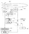
図1は本発明の実施の形態の分析装置のピックアップ107のパワー制御回路を示し、図2〜図4はこの分析装置で使用する分析用光ディスク201を示す。
まず、分析用光ディスク201を説明する。
図2に示す分析用ディスク201は、ピットもしくはグルーブを再生トレース可能であり、ディスクの回転を制御するためのデータ領域と分析対象が配置される読み取りエリアとを有する分析用ディスクであって、前記分析対象が配置される読み取りエリアに対して回転方向の直前位置に、前記読み取りエリアの径方向の区間にわたってマークが記録されている。
図4に示す分析用ディスク201は、ピットもしくはグルーブを再生トレース可能であり、ディスクの回転を制御するためのデータ領域と分析対象が配置される読み取りエリアとを有する分析用ディスクであって、前記分析対象が配置される読み取りエリアに対して回転方向の直前位置と直後位置に、前記読み取りエリアの径方向の区間にわたってマークを記録されている。
【0022】
先ず、図2を説明する。
分析用光ディスク201は、図2に示すように光ディスクに、検体と検査項目に応じた試薬との混合物が分析対象111としてセットされており、分析対象111が配置された読み取りエリア203に対して回転方向Cの直前位置のみに、読み取りエリアの径方向(矢印A方向)の区間にわたってマーク204が記録されている。
【0023】
分析用光ディスク201における分析対象111の位置ならびに分析用光ディスク201に対するマーク204の具体例は、図3に示すように構成されている。
【0024】
図3(a)に示すように、分析対象111は分析用光ディスク201の表面202aとトラック103の間に設けられている。マーク204は分析用光ディスク201の裏面202bにインク205を帯状に印刷して形成されている。この図3(a)において、206は鏡面加工されたトラック103に形成されたピットもしくはグルーブである。207は鏡面加工されたトラック103に形成されたランドである。
【0025】
なお、分析対象111は図3(a)に仮想線で示すように示すように分析用光ディスク201の裏面202bとトラック103の間に設けて構成した場合も同様である。
【0026】
図1に示したパワー制御回路は、APC回路115へフィードバックする入力信号を、切り替えスイッチ208によって切り替えている。この切り替えスイッチ208は、フロントモニタ114の出力信号または積分回路209の出力信号の何れかをAPC回路115へフィードバックしており、この切り替えスイッチ208はマイクロコンピュータ210によって次のように制御されている。
【0027】
マイクロコンピュータ210は、分析用光ディスク201上のEFM信号やウオブル信号を取得する時には、フロントモニタ114の出力信号がAPC回路115へフィードバックされるように切り替えスイッチ208を切り替えて、フロントモニタ114の出力電圧が一定になるようにLD113のレーザー出力がコントロールされる。
【0028】
このようにフロントモニタ114の出力電圧が一定になるようにLD113のレーザー出力がコントロールされている運転中に、PD117の出力信号からマイクロコンピュータ210が前記マーク204を検出すると、マイクロコンピュータ210は、映像信号処理回路112の出力信号を積分して出力する積分回路209の出力信号を、APC回路115へフィードバックされるように切り替えスイッチ208を自動的に切り替えて、分析用光ディスク201の分析対象111の映像の明暗をはっきりさせるため行う。
【0029】
詳しく説明すると、分析対象111からの反射光はPD117でとらえられ、映像信号処理回路112へ入力される。分析用光ディスク201上をトレースしているのはレーザー光ポイント(点)であるため、分析対象111により光の反射は時間とともに強弱に変化することになる。この分析対象111により光の反射は時間とともに強弱に変化する前記PD117の出力信号を、積分回路209によって処理して、映像信号処理回路112から出力される映像の明暗(コントラスト)がほぼ平均値になるようにレーザー光の出力をフィードバック制御している。
【0030】
なお、マーク204を検出してAPC回路115へ積分回路209の出力信号をフィードバックするように切り替えられた切り替えスイッチ208は、マーク204を検出から規定時間後にフロントモニタ114の出力電圧をAPC回路115へフィードバックする状態に戻される。
【0031】
このように構成したため、ピットやグルーブからの情報取得に最適なレーザー出力が得られ、しかも分析対象111からの映像取得に最適なレーザー出力によって映像コントラストが最適な映像出力を得ることができる。
【0032】
上記の実施の形態では、マーク204は分析用光ディスク201の裏面202bにインク205を帯状に印刷して形成したが、図3(b)または(c)に示すようにして構成することもできる。
【0033】
図3(b)の場合は、鏡面加工されたトラック103の一部に鏡面が欠落した個所211を設けてマーク204を同様に実現できる。更に具体的には、DVDのミラー面に設けてあるBCAのようなものである。
【0034】
図3(c)の場合は、分析用光ディスク201の外形の一部に凹部などの形状の異形個所212を設けてマーク204を同様に実現できる。更に具体的には、ディスクそのものの形状を異型させて、光の反射がデータトラック面と変えたものである。
【0035】
上記の各実施の形態では、分析対象111が配置された読み取りエリア203に対して回転方向の直前位置にマーク204を配置し、マイクロコンピュータ210がマーク204を認識してから規程時間後に切り替えスイッチ208を元の状態に復帰させるように構成したが、図4に示すように分析対象111の直前位置だけでなく直後位置にも分析用光ディスク201に同様のマークを設け、マイクロコンピュータ210を分析対象111の直後位置に設けられたマークを検出して切り替えスイッチ208を元の状態に復帰させるように構成することもできる。
【0036】
上記の各実施の形態の分析用光ディスク201のマーク204は、印刷もしくは鏡面欠落もしくは形状異型により形成したが、分析用光ディスク201のピットもしくはグルーブ206もしくはランド207に前記マークを設けることもできる。
【0037】
具体的には、前記マークをピックアップ107で検出することによりトラックデータ部分と前記分析対象111が配置された読み取りエリア203とを区別できるようにしたものであり、以下のような例がある。
【0038】
EFMやMFMなどのピットで構成されたものである。更に具体的には、プリピット、LPP(ランドプリピット)(DVD−R/RWでアドレス情報として記録するトラックとトラックの間のランド部にプリピットとして刻まれているものである。更に具体的には、CAPA(DVD−RAMのアドレス用のプリピット)など。ウォーブルなど、グルーブ上もしくはランド上になんらかの変調を重畳させたものである。
【0039】
分析用ディスク201におけるピットもしくはグルーブもしくはランドで構成される前記マークの詳しい位置と範囲は、前記分析対象111が配置された読み取りエリア203に対して回転方向の直前位置,前後位置の何れかであって、前記の各実施の形態と同じである。
【0040】
ピットもしくはグルーブもしくはランドで前記マークが形成された分析用ディスク201を使用する分析装置は、ピックアップ107が前記マークを読み取ってマーク位置を検出した各トリガー信号を発生するように構成した点だけが前記の各実施の形態とは異なっている。
【0041】
なお、上記の各実施の形態では、ピックアップ107のLD113とPD117とを光ディスク101に対して片側に設け、光ディスク101に照射されて反射したレーザー光の検出信号を処理するように構成したが、ピックアップ107を、図9に仮想線で示したように、光ディスク101を挟んでLD113とPD117を配設して、光ディスク101に照射されて透過したレーザー光の検出信号を処理するように構成された光ディスクドライブのピックアップ107のパワー制御回路も図1と同様である。
【0042】
【発明の効果】
以上のように本発明の分析装置によれば、一部に分析対象を配置した分析用光ディスクにレーザー光を照射し、前記分析対象に照射されて反射または透過して読み取った検出光をフォトディテクタで検出し、前記フォトディテクタの出力信号を映像信号処理回路で処理して映像信号を出力して前記分析対象の状態を読み取る分析装置であって、前記レーザー光を発生するレーザー素子を駆動するレーザー駆動回路と、前記レーザー素子から発生したレーザー光の強度を検出するフロントモニタと、前記フロントモニタの検出電圧を入力信号として前記レーザー駆動回路をフィードバック制御するオートパワーコントロール回路と、前記映像信号処理回路の出力信号を積分して出力する積分回路と、前記フロントモニタの検出電圧を前記オートパワーコントロール回路への前記入力信号として出力する第1の切り替え状態と前記積分回路の出力電圧を前記オートパワーコントロール回路への前記入力信号として出力する第2の切り替え状態を有する切り替えスイッチと、前記分析対象の読み取り位置を検出するまでは前記切り替えスイッチを第1の切り替え状態に切り替えて運転し、第1の切り替え状態に切り替えて運転中に分析用光ディスクの分析対象の読み取り位置になったことを検出して前記切り替えスイッチを第2の切り替え状態に切り替えて運転する制御手段を設けたため、ピットやグルーブからの情報取得に最適なレーザー出力が得られ、しかも分析対象からの映像取得に最適なレーザー出力が得られ、コントラストの良い映像が取得できるものである。
【図面の簡単な説明】
【図1】本発明の分析装置の構成図
【図2】同実施の形態で使用する分析用光ディスクの平面図
【図3】同実施の形態の分析用光ディスクの断面図
【図4】分析対象の前後位置にマークを設けた分析用光ディスクの平面図
【図5】一般的な光ディスクドライブ装置の構成図
【図6】従来の分析用光ディスクの一部切り欠き平面図
【図7】従来の分析用光ディスクの断面図
【図8】従来のピックアップのパワー制御回路の構成図
【図9】従来の透過型ピックアップのLD(レーザーLED)とPD(フォトディテクタ)の配置状態を示す分析用光ディスクの断面図
【符号の説明】
106 ディスクモータ
107 ピックアップ
Ph レーザー光
111 分析対象
117 PD(フォトディテクタ)
112 映像信号処理回路
113 LD(レーザーLED)
114 フロントモニタ
115 APC回路(オートパワーコントロール回路)
116 レーザー駆動回路
201 分析用光ディスク
203 読み取りエリア
204 マーク
202a 分析用光ディスク201の表面
202b 分析用光ディスク201の裏面
205 インク
206 ピットもしくはグルーブ
207 ランド
208 切り替えスイッチ
209 積分回路
210 マイクロコンピュータ[0001]
BACKGROUND OF THE INVENTION
The present invention relates to an analysis apparatus that sets an analysis target such as blood on an optical disc for analysis and traces the analysis target as an image.
[0002]
[Prior art]
As disclosed in Japanese Patent Publication No. 10-504397, there is a method of obtaining an analysis target image by providing an analysis target to be tested in a certain part on the disk using a playback function of the optical disk.
[0003]
Normally, as shown in FIGS. 6 and 7, the
[0004]
In the general optical disk drive shown in FIG. 5, while the
[0005]
More specifically, the irradiation position of the laser beam Ph on the
[0006]
Here, in the case of the disc for analysis, unlike the case of CD for audio and video, the
[0007]
FIG. 8 shows a power control circuit of the
Laser light output for reading information written in the pits and grooves of the
[0008]
The output voltage of the
[0009]
In the optical disk drive shown in FIGS. 5 and 8, the
[0010]
[Problems to be solved by the invention]
However, the optimal laser output for acquiring the image of the portion of the
[0011]
This is because the laser path for acquiring information from the pits and grooves provided in the
[0012]
An object of the present invention is to provide an analyzer capable of obtaining a laser output optimum for acquiring information from a pit or groove and obtaining an optimum laser output for obtaining an image from the
[0013]
[Means for Solving the Problems]
In order to solve this problem, the present invention is configured to control the detected video based on the brightness of the image when the video to be analyzed is acquired. As a result, an image with the optimum contrast can be obtained when acquiring the image from the analysis target.
[0014]
The analyzer according to claim 1 of the present invention irradiates an analysis optical disk in which an analysis target is partially arranged with a laser beam, and detects the detection light read by being reflected on or transmitted through the analysis target with a photodetector. And an analysis device for processing the output signal of the photodetector by a video signal processing circuit and outputting the video signal to read the state of the analysis object,and a laser driving circuit for driving a laser elementthat generates the laser light; A front monitor for detecting the intensity of laser light generated from the laser element, an auto power control circuit for feedback control of the laser driving circuit using a detection voltage of the front monitor as an input signal, and an output signal of the video signal processing circuit An integration circuit that integrates and outputs the detected voltage of the front monitor. A changeover switch having a first switching state that is output as the input signal to the control circuit, and a second switching state that outputs the output voltage of the integration circuit as the input signal to the auto power control circuit; Until the reading position is detected, the changeover switch is switched to the first switching state to operate, and the first switching state is switched to detect that the reading position of the analysis optical disc is reached during the operation. And a control means for operating the switch by switching the switch to the second switching state .
[0015]
According to a second aspect of the present invention, in the first aspect of the present invention, the control means detects the mark provided immediately before the reading position defined in the radial direction of the optical disk for analysis and sets the secondswitch to the second position. It is characterized by being configured to switch to the switching state.
[0016]
According to a third aspect of the present invention, in the analysis device according to the first aspect, the control means detects the mark provided immediately before the reading position defined in the radial direction of the analysis optical disc and sets the secondswitch to the second position. It is configured to switch to the switching state, and to detect the elapse of a specified time and return the switchingswitch to the first switching state.
[0017]
According to a fourth aspect of the present invention, there is provided the analyzer according to the first aspect, wherein the control means detects a mark provided immediately before the reading position defined in the radial direction of the optical disc for analysis and sets thechangeover switch to the second position. In this case, the mark is provided immediately after the reading position, and thechangeover switch is returned to the first switching state.
[0020]
DETAILED DESCRIPTION OF THE INVENTION
Hereinafter, embodiments of the present invention will be described with reference to FIGS.
In addition, the same code | symbol is attached | subjected and demonstrated to the thing similar to the prior art example shown in FIGS.
[0021]
FIG. 1 shows a power control circuit of a
First, the analysis
The
The
[0022]
First, FIG. 2 will be described.
As shown in FIG. 2, the analysis
[0023]
The specific example of the position of the
[0024]
As shown in FIG. 3A, the
[0025]
Incidentally, the
[0026]
In the power control circuit shown in FIG. 1, an input signal fed back to the
[0027]
When the
[0028]
When the
[0029]
More specifically, the reflected light from the
[0030]
The
[0031]
With this configuration, it is possible to obtain an optimum laser output for acquiring information from pits and grooves, and to obtain an image output having an optimum image contrast by an optimum laser output for obtaining an image from the
[0032]
In the above embodiment, the
[0033]
In the case of FIG. 3B, the
[0034]
In the case of FIG. 3C, the
[0035]
In each of the above-described embodiments, the
[0036]
The
[0037]
Specifically, the track data portion and the
[0038]
It is composed of pits such as EFM and MFM. More specifically, pre-pits, LPP (land pre-pits) (recorded as address information on a DVD-R / RW are recorded as pre-pits in a land portion between tracks. More specifically, , CAPA (DVD-RAM address pre-pits), etc. Wobble, etc., with some modulation superimposed on the groove or land.
[0039]
The detailed position and range of the mark composed of pits, grooves, or lands on the
[0040]
The analysis apparatus using the
[0041]
In each of the above embodiments, the
[0042]
【The invention's effect】
As described above, according to the analysis apparatus of the present invention, a laser beam is applied to an analysis optical disk in which an analysis target is partially arranged, and the detection light that is irradiated to the analysis target and reflected or transmitted is read by a photodetector. A laser driving circuit that detects and processes an output signal of the photodetector by a video signal processing circuit and outputs a video signal to read the state of the analysis target, and drives a laser element that generates the laser light A front monitor for detecting the intensity of laser light generated from the laser element, an auto power control circuit for feedback control of the laser drive circuit using a detection voltage of the front monitor as an input signal, and an output of the video signal processing circuit An integration circuit that integrates and outputs the signal, and the detection voltage of the front monitor A changeover switch having a first switching state that is output as the input signal to the word control circuit and a second switching state that outputs the output voltage of the integration circuit as the input signal to the auto power control circuit; Until the reading position of the object is detected, the changeover switch is switched to the first switching state for operation, and the first switching state is switched to detect that the reading position of the analysis optical disc is reached during operation. Since the control means for switching and operating the changeover switch to the second changeover state is provided, the optimum laser output for obtaining information from the pits and grooves can be obtained, and the optimum laser output for obtaining images from the analysis target. Can be obtained and images with good contrast can be obtained.
[Brief description of the drawings]
FIG. 1 is a configuration diagram of an analysis apparatus according to the present invention. FIG. 2 is a plan view of an analysis optical disk used in the embodiment. FIG. 3 is a cross-sectional view of an analysis optical disk according to the embodiment. Fig. 5 is a plan view of a general optical disc drive device provided with marks before and after the position. Fig. 6 is a partially cutaway plan view of a conventional optical disc for analysis. Fig. 7 is a conventional analysis. FIG. 8 is a configuration diagram of a power control circuit of a conventional pickup. FIG. 9 is a cross-sectional view of an analysis optical disk showing an arrangement state of LD (laser LED) and PD (photo detector) of a conventional transmissive pickup. [Explanation of symbols]
106
112 Video
114
116
Claims (4)
Translated fromJapanese前記レーザー光を発生するレーザー素子を駆動するレーザー駆動回路と、
前記レーザー素子から発生したレーザー光の強度を検出するフロントモニタと、
前記フロントモニタの検出電圧を入力信号として前記レーザー駆動回路をフィードバック制御するオートパワーコントロール回路と、
前記映像信号処理回路の出力信号を積分して出力する積分回路と、
前記フロントモニタの検出電圧を前記オートパワーコントロール回路への前記入力信号として出力する第1の切り替え状態と前記積分回路の出力電圧を前記オートパワーコントロール回路への前記入力信号として出力する第2の切り替え状態を有する切り替えスイッチと、
前記分析対象の読み取り位置を検出するまでは前記切り替えスイッチを第1の切り替え状態に切り替えて運転し、第1の切り替え状態に切り替えて運転中に分析用光ディスクの分析対象の読み取り位置になったことを検出して前記切り替えスイッチを第2の切り替え状態に切り替えて運転する制御手段と
を設けた分析装置。Laser light is applied to an optical disc for analysis in which an analysis target is partially arranged, detection light that is read by being reflected or transmitted through the analysis target is detected by a photo detector, and an output signal of the photo detector is a video signal processing circuit An analysis apparatus that reads the state of the analysis target by processing a video signal and outputting the video signal,
A laser driving circuit that drives a laser element that generates the laser light;
A front monitor for detecting the intensity of laser light generated from the laser element;
An auto power control circuit that feedback-controls the laser drive circuit using the detection voltage of the front monitor as an input signal;
An integration circuit for integrating and outputting the output signal of the video signal processing circuit;
A first switching state in which the detection voltage of the front monitor is output as the input signal to the auto power control circuit and a second switching in which the output voltage of the integration circuit is output as the input signal to the auto power control circuit A changeover switch having a state;
Until the reading position of the analysis target is detected, the changeover switch is switched to the first switching state and the driving is performed, and the first switching state is switched to the reading position of the analysis optical disc during the driving. And a control means for operating by switching the changeover switch to the second changeover state.
Analyzing deviceprovided .
請求項1記載の分析装置。2. The analyzer according to claim 1,wherein the control means is configured to detect a mark provided immediately before the reading position defined in the radial direction of the optical disk for analysis and toswitch the changeover switch to the second switching state.
請求項1記載の分析装置。The control means detects the mark provided immediately before the reading position defined in the radial direction of the analysis optical disk,switches the changeover switch to the second changeover state, detects the passage of a prescribed time, and detects thechangeover switch. 2. The analyzer according to claim 1, wherein the analyzer is configured to return to the first switching state.
請求項1記載の分析装置。The control means detects a mark provided immediately before the reading position defined in the radial direction of the analysis optical disc,switches the changeover switch to the second switching state, and sets the mark provided immediately after the reading position. The analyzer according to claim 1, wherein the analyzer is configured to detect the error and to return thechangeover switch to the first changeover state.
Priority Applications (5)
| Application Number | Priority Date | Filing Date | Title |
|---|---|---|---|
| JP2002177828AJP4148705B2 (en) | 2002-06-19 | 2002-06-19 | Analysis equipment |
| US10/518,028US7423246B2 (en) | 2002-06-19 | 2003-05-29 | Analysis apparatus and analysis disc used for the same |
| CNB03814266XACN100458404C (en) | 2002-06-19 | 2003-05-29 | Analyzing apparatus and analyzed disc used in the same |
| EP03733181AEP1526371B1 (en) | 2002-06-19 | 2003-05-29 | Analyzing apparatus |
| PCT/JP2003/006790WO2004001396A1 (en) | 2002-06-19 | 2003-05-29 | Analyzing apparatus and analyzed disc used in the same |
Applications Claiming Priority (1)
| Application Number | Priority Date | Filing Date | Title |
|---|---|---|---|
| JP2002177828AJP4148705B2 (en) | 2002-06-19 | 2002-06-19 | Analysis equipment |
Publications (2)
| Publication Number | Publication Date |
|---|---|
| JP2004020452A JP2004020452A (en) | 2004-01-22 |
| JP4148705B2true JP4148705B2 (en) | 2008-09-10 |
Family
ID=29996496
Family Applications (1)
| Application Number | Title | Priority Date | Filing Date |
|---|---|---|---|
| JP2002177828AExpired - LifetimeJP4148705B2 (en) | 2002-06-19 | 2002-06-19 | Analysis equipment |
Country Status (5)
| Country | Link |
|---|---|
| US (1) | US7423246B2 (en) |
| EP (1) | EP1526371B1 (en) |
| JP (1) | JP4148705B2 (en) |
| CN (1) | CN100458404C (en) |
| WO (1) | WO2004001396A1 (en) |
Families Citing this family (13)
| Publication number | Priority date | Publication date | Assignee | Title |
|---|---|---|---|---|
| JP2007516149A (en) | 2003-05-21 | 2007-06-21 | アレックザ ファーマシューティカルズ, インコーポレイテッド | Method for controlling uniformity of substrate temperature, built-in heating unit and chemical supply unit using the same |
| JP2005108342A (en)* | 2003-09-30 | 2005-04-21 | Pioneer Electronic Corp | Driving unit and information processor |
| US7496026B2 (en)* | 2004-12-11 | 2009-02-24 | Hewlett-Packard Development Company, L.P. | Optical disc and method of printing optical disc |
| US20070023643A1 (en) | 2005-02-01 | 2007-02-01 | Nolte David D | Differentially encoded biological analyzer planar array apparatus and methods |
| US7910356B2 (en) | 2005-02-01 | 2011-03-22 | Purdue Research Foundation | Multiplexed biological analyzer planar array apparatus and methods |
| US7405831B2 (en) | 2005-02-01 | 2008-07-29 | Purdue Research Foundation | Laser scanning interferometric surface metrology |
| GB0525665D0 (en)* | 2005-12-16 | 2006-01-25 | Filtrona Plc | Detector and method of detection |
| US7522282B2 (en) | 2006-11-30 | 2009-04-21 | Purdue Research Foundation | Molecular interferometric imaging process and apparatus |
| WO2008089495A2 (en) | 2007-01-19 | 2008-07-24 | Purdue Research Foundation | System with extended range of molecular sensing through integrated multi-modal data acquisition |
| CA2681722A1 (en) | 2007-03-26 | 2008-10-02 | Purdue Research Foundation | Method and apparatus for conjugate quadrature interferometric detection of an immunoassay |
| JP2009093715A (en)* | 2007-10-04 | 2009-04-30 | Sony Corp | Data recording and reproducing device, camera device, and data recording and reproducing method |
| CN104007074B (en)* | 2014-05-26 | 2016-03-23 | 上海理工大学 | Double-beam spectrophotometer and its collection, analysis and processing method |
| CN111387599B (en)* | 2020-04-16 | 2025-03-18 | 成都益英光电科技有限公司 | Droplet capture device based on coherent light imaging and rapid screening method for viral nucleic acid |
Family Cites Families (14)
| Publication number | Priority date | Publication date | Assignee | Title |
|---|---|---|---|---|
| JPH03225278A (en)* | 1990-01-31 | 1991-10-04 | Idemitsu Petrochem Co Ltd | Disk for analyzing liquid sample |
| JPH02269938A (en) | 1989-04-11 | 1990-11-05 | Idemitsu Petrochem Co Ltd | Analysis apparatus |
| JPH04233462A (en)* | 1990-12-28 | 1992-08-21 | Idemitsu Petrochem Co Ltd | Immunological quantitative analysis |
| JPH055741A (en)* | 1990-10-09 | 1993-01-14 | Idemitsu Petrochem Co Ltd | Method for immunological quantitative analysis |
| JPH07209185A (en)* | 1994-01-13 | 1995-08-11 | Yokogawa Electric Corp | Surface scattering type turbidimeter |
| GB9418981D0 (en)* | 1994-09-21 | 1994-11-09 | Univ Glasgow | Apparatus and method for carrying out analysis of samples |
| JP3372396B2 (en)* | 1995-06-14 | 2003-02-04 | 株式会社日立製作所 | Optical disk drive |
| US5822285A (en)* | 1997-03-31 | 1998-10-13 | International Business Machines Corporation | Atomic force microscopy disk data storage system with nonradial tracking lines |
| EP1004015B1 (en)* | 1997-08-15 | 2004-01-02 | Alexion Pharmaceuticals, Inc. | Apparatus for performing assays at reaction sites |
| US5922617A (en)* | 1997-11-12 | 1999-07-13 | Functional Genetics, Inc. | Rapid screening assay methods and devices |
| JP4068752B2 (en)* | 1999-03-02 | 2008-03-26 | シャープ株式会社 | Optical disk device |
| AU2001264730A1 (en)* | 2000-08-21 | 2002-03-04 | Burstein Technologies, Inc. | Methods and apparatus for optical disc data acquisition using physical synchronization markers |
| US7061594B2 (en)* | 2000-11-09 | 2006-06-13 | Burstein Technologies, Inc. | Disc drive system and methods for use with bio-discs |
| US7026131B2 (en)* | 2000-11-17 | 2006-04-11 | Nagaoka & Co., Ltd. | Methods and apparatus for blood typing with optical bio-discs |
- 2002
- 2002-06-19JPJP2002177828Apatent/JP4148705B2/ennot_activeExpired - Lifetime
- 2003
- 2003-05-29EPEP03733181Apatent/EP1526371B1/ennot_activeExpired - Lifetime
- 2003-05-29CNCNB03814266XApatent/CN100458404C/ennot_activeExpired - Fee Related
- 2003-05-29WOPCT/JP2003/006790patent/WO2004001396A1/ennot_activeCeased
- 2003-05-29USUS10/518,028patent/US7423246B2/ennot_activeExpired - Lifetime
Also Published As
| Publication number | Publication date |
|---|---|
| JP2004020452A (en) | 2004-01-22 |
| EP1526371A1 (en) | 2005-04-27 |
| EP1526371A4 (en) | 2010-07-14 |
| CN100458404C (en) | 2009-02-04 |
| EP1526371B1 (en) | 2013-01-23 |
| WO2004001396A1 (en) | 2003-12-31 |
| US7423246B2 (en) | 2008-09-09 |
| CN1662806A (en) | 2005-08-31 |
| US20050259260A1 (en) | 2005-11-24 |
Similar Documents
| Publication | Publication Date | Title |
|---|---|---|
| US5959280A (en) | Multi-standard optical disk reading apparatus and method of reading using same | |
| JP4148705B2 (en) | Analysis equipment | |
| US7746747B2 (en) | Optical recording medium drive apparatus and method of determining the number of layers | |
| US6137758A (en) | Optical disc discriminating apparatus | |
| US20080165657A1 (en) | Optical pickup apparatus and optical disk drive apparatus | |
| US8149668B2 (en) | Optical disk drive and method for determining disk type | |
| JP4194787B2 (en) | Analysis device and analysis disk used for it | |
| US20030095487A1 (en) | Type distinction method of optical disk and optical disk apparatus using the method | |
| KR20040041951A (en) | Apparatus for discriminating type of disc in the disc drive and method thereof | |
| US20070076546A1 (en) | Optical disc apparatus and tracking error signal selecting method | |
| CN100412959C (en) | Information recording device and method, information reproducing device and method | |
| US5859830A (en) | Dynamic tracking control in an optical recording system by diffraction-based mark formation detection | |
| US7782727B2 (en) | Optical disk processing apparatus | |
| KR20050007811A (en) | Method of discriminating optical disc type and apparatus thereof | |
| US20080298205A1 (en) | Optical disc apparatus and optical disc distinguishing method | |
| EP1355302A2 (en) | Tilt detection device including a light-shielding member of light at both sides in radial direction of the optical disk | |
| KR20050118810A (en) | The method and the device of compensating the defect on the basis of discriminating between the recorded area and the unrecorded area in the | |
| US7593293B2 (en) | Optical disk drive | |
| US20070076087A1 (en) | Optical disc apparatus | |
| JP2003030830A (en) | Optical disc determination method and optical disc apparatus | |
| KR19990057689A (en) | Optical disc player | |
| JP2006300696A (en) | Optical analyzer | |
| JP2003173532A (en) | Light emission output control method for optical head | |
| JP2009059435A (en) | Optical pickup and optical disc apparatus | |
| JP2003317252A (en) | Apparatus for inspecting defect of optical disk |
Legal Events
| Date | Code | Title | Description |
|---|---|---|---|
| A621 | Written request for application examination | Free format text:JAPANESE INTERMEDIATE CODE: A621 Effective date:20050620 | |
| A131 | Notification of reasons for refusal | Free format text:JAPANESE INTERMEDIATE CODE: A131 Effective date:20070410 | |
| A521 | Request for written amendment filed | Free format text:JAPANESE INTERMEDIATE CODE: A523 Effective date:20070607 | |
| A131 | Notification of reasons for refusal | Free format text:JAPANESE INTERMEDIATE CODE: A131 Effective date:20070731 | |
| A521 | Request for written amendment filed | Free format text:JAPANESE INTERMEDIATE CODE: A523 Effective date:20070928 | |
| A02 | Decision of refusal | Free format text:JAPANESE INTERMEDIATE CODE: A02 Effective date:20071204 | |
| A521 | Request for written amendment filed | Free format text:JAPANESE INTERMEDIATE CODE: A523 Effective date:20080128 | |
| A911 | Transfer to examiner for re-examination before appeal (zenchi) | Free format text:JAPANESE INTERMEDIATE CODE: A911 Effective date:20080212 | |
| A131 | Notification of reasons for refusal | Free format text:JAPANESE INTERMEDIATE CODE: A131 Effective date:20080408 | |
| A521 | Request for written amendment filed | Free format text:JAPANESE INTERMEDIATE CODE: A523 Effective date:20080424 | |
| RD04 | Notification of resignation of power of attorney | Free format text:JAPANESE INTERMEDIATE CODE: A7424 Effective date:20080430 | |
| TRDD | Decision of grant or rejection written | ||
| A01 | Written decision to grant a patent or to grant a registration (utility model) | Free format text:JAPANESE INTERMEDIATE CODE: A01 Effective date:20080527 | |
| A01 | Written decision to grant a patent or to grant a registration (utility model) | Free format text:JAPANESE INTERMEDIATE CODE: A01 | |
| A61 | First payment of annual fees (during grant procedure) | Free format text:JAPANESE INTERMEDIATE CODE: A61 Effective date:20080624 | |
| FPAY | Renewal fee payment (event date is renewal date of database) | Free format text:PAYMENT UNTIL: 20110704 Year of fee payment:3 | |
| R151 | Written notification of patent or utility model registration | Ref document number:4148705 Country of ref document:JP Free format text:JAPANESE INTERMEDIATE CODE: R151 | |
| FPAY | Renewal fee payment (event date is renewal date of database) | Free format text:PAYMENT UNTIL: 20110704 Year of fee payment:3 | |
| FPAY | Renewal fee payment (event date is renewal date of database) | Free format text:PAYMENT UNTIL: 20110704 Year of fee payment:3 | |
| FPAY | Renewal fee payment (event date is renewal date of database) | Free format text:PAYMENT UNTIL: 20120704 Year of fee payment:4 | |
| FPAY | Renewal fee payment (event date is renewal date of database) | Free format text:PAYMENT UNTIL: 20120704 Year of fee payment:4 | |
| FPAY | Renewal fee payment (event date is renewal date of database) | Free format text:PAYMENT UNTIL: 20130704 Year of fee payment:5 | |
| S111 | Request for change of ownership or part of ownership | Free format text:JAPANESE INTERMEDIATE CODE: R313113 | |
| S533 | Written request for registration of change of name | Free format text:JAPANESE INTERMEDIATE CODE: R313533 | |
| R350 | Written notification of registration of transfer | Free format text:JAPANESE INTERMEDIATE CODE: R350 | |
| S111 | Request for change of ownership or part of ownership | Free format text:JAPANESE INTERMEDIATE CODE: R313113 | |
| R350 | Written notification of registration of transfer | Free format text:JAPANESE INTERMEDIATE CODE: R350 | |
| S111 | Request for change of ownership or part of ownership | Free format text:JAPANESE INTERMEDIATE CODE: R313113 | |
| R350 | Written notification of registration of transfer | Free format text:JAPANESE INTERMEDIATE CODE: R350 | |
| R250 | Receipt of annual fees | Free format text:JAPANESE INTERMEDIATE CODE: R250 | |
| R250 | Receipt of annual fees | Free format text:JAPANESE INTERMEDIATE CODE: R250 | |
| R250 | Receipt of annual fees | Free format text:JAPANESE INTERMEDIATE CODE: R250 | |
| S533 | Written request for registration of change of name | Free format text:JAPANESE INTERMEDIATE CODE: R313533 | |
| R350 | Written notification of registration of transfer | Free format text:JAPANESE INTERMEDIATE CODE: R350 | |
| R250 | Receipt of annual fees | Free format text:JAPANESE INTERMEDIATE CODE: R250 | |
| R250 | Receipt of annual fees | Free format text:JAPANESE INTERMEDIATE CODE: R250 | |
| R250 | Receipt of annual fees | Free format text:JAPANESE INTERMEDIATE CODE: R250 | |
| R250 | Receipt of annual fees | Free format text:JAPANESE INTERMEDIATE CODE: R250 | |
| EXPY | Cancellation because of completion of term |