JP4147832B2 - Wireless communication system, image forming apparatus, and cartridge part - Google Patents
Wireless communication system, image forming apparatus, and cartridge partDownload PDFInfo
- Publication number
- JP4147832B2 JP4147832B2JP2002175535AJP2002175535AJP4147832B2JP 4147832 B2JP4147832 B2JP 4147832B2JP 2002175535 AJP2002175535 AJP 2002175535AJP 2002175535 AJP2002175535 AJP 2002175535AJP 4147832 B2JP4147832 B2JP 4147832B2
- Authority
- JP
- Japan
- Prior art keywords
- tag
- wireless communication
- cartridge
- main body
- toner
- Prior art date
- Legal status (The legal status is an assumption and is not a legal conclusion. Google has not performed a legal analysis and makes no representation as to the accuracy of the status listed.)
- Expired - Fee Related
Links
Images


Classifications
- G—PHYSICS
- G03—PHOTOGRAPHY; CINEMATOGRAPHY; ANALOGOUS TECHNIQUES USING WAVES OTHER THAN OPTICAL WAVES; ELECTROGRAPHY; HOLOGRAPHY
- G03G—ELECTROGRAPHY; ELECTROPHOTOGRAPHY; MAGNETOGRAPHY
- G03G15/00—Apparatus for electrographic processes using a charge pattern
- G03G15/55—Self-diagnostics; Malfunction or lifetime display
- G03G15/553—Monitoring or warning means for exhaustion or lifetime end of consumables, e.g. indication of insufficient copy sheet quantity for a job
- B—PERFORMING OPERATIONS; TRANSPORTING
- B41—PRINTING; LINING MACHINES; TYPEWRITERS; STAMPS
- B41J—TYPEWRITERS; SELECTIVE PRINTING MECHANISMS, i.e. MECHANISMS PRINTING OTHERWISE THAN FROM A FORME; CORRECTION OF TYPOGRAPHICAL ERRORS
- B41J2/00—Typewriters or selective printing mechanisms characterised by the printing or marking process for which they are designed
- B41J2/005—Typewriters or selective printing mechanisms characterised by the printing or marking process for which they are designed characterised by bringing liquid or particles selectively into contact with a printing material
- B41J2/01—Ink jet
- B41J2/17—Ink jet characterised by ink handling
- B41J2/175—Ink supply systems ; Circuit parts therefor
- B41J2/17503—Ink cartridges
- B41J2/17543—Cartridge presence detection or type identification
- B41J2/17546—Cartridge presence detection or type identification electronically
- G—PHYSICS
- G03—PHOTOGRAPHY; CINEMATOGRAPHY; ANALOGOUS TECHNIQUES USING WAVES OTHER THAN OPTICAL WAVES; ELECTROGRAPHY; HOLOGRAPHY
- G03G—ELECTROGRAPHY; ELECTROPHOTOGRAPHY; MAGNETOGRAPHY
- G03G15/00—Apparatus for electrographic processes using a charge pattern
- G03G15/06—Apparatus for electrographic processes using a charge pattern for developing
- G03G15/08—Apparatus for electrographic processes using a charge pattern for developing using a solid developer, e.g. powder developer
- G03G15/0822—Arrangements for preparing, mixing, supplying or dispensing developer
- G03G15/0848—Arrangements for testing or measuring developer properties or quality, e.g. charge, size, flowability
- G03G15/0849—Detection or control means for the developer concentration
- G03G15/0855—Detection or control means for the developer concentration the concentration being measured by optical means
- G—PHYSICS
- G03—PHOTOGRAPHY; CINEMATOGRAPHY; ANALOGOUS TECHNIQUES USING WAVES OTHER THAN OPTICAL WAVES; ELECTROGRAPHY; HOLOGRAPHY
- G03G—ELECTROGRAPHY; ELECTROPHOTOGRAPHY; MAGNETOGRAPHY
- G03G15/00—Apparatus for electrographic processes using a charge pattern
- G03G15/06—Apparatus for electrographic processes using a charge pattern for developing
- G03G15/08—Apparatus for electrographic processes using a charge pattern for developing using a solid developer, e.g. powder developer
- G03G15/0822—Arrangements for preparing, mixing, supplying or dispensing developer
- G03G15/0863—Arrangements for preparing, mixing, supplying or dispensing developer provided with identifying means or means for storing process- or use parameters, e.g. an electronic memory
- G—PHYSICS
- G03—PHOTOGRAPHY; CINEMATOGRAPHY; ANALOGOUS TECHNIQUES USING WAVES OTHER THAN OPTICAL WAVES; ELECTROGRAPHY; HOLOGRAPHY
- G03G—ELECTROGRAPHY; ELECTROPHOTOGRAPHY; MAGNETOGRAPHY
- G03G15/00—Apparatus for electrographic processes using a charge pattern
- G03G15/06—Apparatus for electrographic processes using a charge pattern for developing
- G03G15/08—Apparatus for electrographic processes using a charge pattern for developing using a solid developer, e.g. powder developer
- G03G15/0822—Arrangements for preparing, mixing, supplying or dispensing developer
- G03G15/0865—Arrangements for supplying new developer
- G03G15/0867—Arrangements for supplying new developer cylindrical developer cartridges, e.g. toner bottles for the developer replenishing opening
- G03G15/087—Developer cartridges having a longitudinal rotational axis, around which at least one part is rotated when mounting or using the cartridge
- G03G15/0872—Developer cartridges having a longitudinal rotational axis, around which at least one part is rotated when mounting or using the cartridge the developer cartridges being generally horizontally mounted parallel to its longitudinal rotational axis
- G—PHYSICS
- G03—PHOTOGRAPHY; CINEMATOGRAPHY; ANALOGOUS TECHNIQUES USING WAVES OTHER THAN OPTICAL WAVES; ELECTROGRAPHY; HOLOGRAPHY
- G03G—ELECTROGRAPHY; ELECTROPHOTOGRAPHY; MAGNETOGRAPHY
- G03G15/00—Apparatus for electrographic processes using a charge pattern
- G03G15/55—Self-diagnostics; Malfunction or lifetime display
Landscapes
- Physics & Mathematics (AREA)
- General Physics & Mathematics (AREA)
- Control Or Security For Electrophotography (AREA)
- Dry Development In Electrophotography (AREA)
- Electrophotography Configuration And Component (AREA)
- Facsimiles In General (AREA)
- Near-Field Transmission Systems (AREA)
Description
Translated fromJapanese【0001】
【発明の属する技術分野】
本発明は、装置本体に複数個のカートリッジ部品が着脱可能に装着される各種の装置に適用される無線通信システム及び、装置本体に複数個のカートリッジ部品がそれぞれ着脱可能に装着される複写機、ファクシミリ、プリンター等の画像形成装置及び、これらの無線通信システム及び画像形成装置に用いられるカートリッジ部品に関するものである。
【0002】
【従来の技術】
電子写真プロセスを用いた複写機、レーザプリンタ等の画像形成装置には、メンテナンスを容易にするために、トナーを収容する容器がトナーカートリッジとして構成されたものがある。このような画像形成装置では、トナーカートリッジ内から全てのトナーが排出されると、ユーザによりトナーカートリッジが新しいものに交換されることでトナー補給が行われる。このとき、画像形成装置から取り外された使用済みトナーカートリッジは、多くの場合、ユーザから画像形成装置のメーカーへ返却され、メーカーにより検査、清掃、消耗部品の交換、トナーの再充填等のリサイクル工程を経て、ユーザへ再出荷される。また、上記のような画像形成装置がカラー画像の形成可能なものである場合には、装置本体における異なる部位に設けられたカートリッジ装着部にそれぞれ異なる種類(例えば、クロ、シアン、マゼンタ、イエローに対応する4種類)のトナーカートリッジが装着され、これらのトナーカートリッジからそれぞれ異なる色のトナーが装置本体側へ供給される。
【0003】
さらに、上記のような画像形成装置には、作像プロセスに関わるプロセス部品として、電子写真感光体(以下、単に「感光体」という。)にトナーを付着させる現像器、感光体からのトナー像の転写完了後に残留トナーを回収するクリーニング器、感光体の像担持面を所定電位に帯電する帯電器等が設けられており、これらのプロセス部品の少なくとも1個以上が感光体と共に一体的に支持されるプロセスカートリッジを備えたものがある。プロセスカートリッジは、構成部品のうち何れかの耐用期間が経過した場合に新しいものに交換される。画像形成装置から取り外さされたプロセスカートリッジは、多くの場合、ユーザからメーカーへ返却され、メーカーにより検査、清掃、耐用期間が経過した部品の交換等のリサイクル工程を経て、画像形成装置を使用するユーザへ再出荷される。
【0004】
近年、上記のような画像形成装置には、トナーカートリッジやプロセスカートリッジ等のカートリッジ部品にそれぞれ電波通信機能及び情報の記憶機能を有するタグ(無線通信タグ)を取り付け、装置本体側には無線通信タグとの間で情報の入出力を行うための無線通信装置が配置されたものがある。この種の画像形成装置では、装置本体にカートリッジ部品が装着されると、無線通信装置とカートリッジタグとの間で電波通信を行うことで、本体制御部がカートリッジタグに記憶された情報を読み取り、又はカートリッジタグに情報を書き込むことが行われる。これにより、例えば、本体制御部がカートリッジタグからカートリッジ部品の種類に対応する情報を読み取ることで、装置本体における所定の装着部に本来、装着すべきカートリッジ部品とは異なる種類のものが誤装着された場合にも、カートリッジ部品の誤装着を判断し、エラー処理等の必要な制御を行える。また、本体制御部が画像形成回数等に基づくカートリッジ部品の使用履歴を無線通信タグに書き込むようにすれば、メーカ等では、ユーザから返却されてきたカートリッジ部品の無線通信タグから使用履歴に関する情報を読み取ることで、カートリッジ部品に対するリサイクル工程における検査作業や部品交換作業を効率的に、かつ的確に行える。
【0005】
また、上記のようなカートリッジ部品に取り付けられる無線通信タグには、無線通信、情報処理等の作動時における消費電力が装置本体側の無線通信装置から電磁誘導により供給されるものがある。これにより、無線通信タグには、バッテリ等の電源を搭載する必要がなくなり、小型化、コスト抑制の観点から有利になる。
【0006】
上記のような電磁誘導により電力が供給される無線通信タグを備えた画像形成装置としては、例えば、特開2001−222230号公報に開示されたものがある。この画像形成装置では、プロセスカートリッジ及び現像器をカートリッジ部品とした現像カートリッジにそれぞれ無線通信タグが取り付けられ、装置本体側には無線通信装置が配置されている。
【0007】
ここで、無線通信タグ及び無線通信装置には、金属薄膜をコイル状に巻き回して形成された本体側アンテナ及びタグ側アンテナがそれぞれ設けられている。この無線通信タグ及び無線通信装置からなる無線通信システムにおいては、無線通信タグへの電力供給を電磁誘導により行い、かつ電磁誘導により無線通信タグに供給される微弱電力を用いて電波通信を確実に行うためには、無線通信装置の本体側アンテナと無線通信タグのタグ側アンテナとを互いに略平行な状態乃至僅かに傾いた状態で対向させると共に、本体側アンテナと無線通信タグのタグ側アンテナとの間隔を十分に小さくする必要がある。
【0008】
また、カラー画像が形成可能な画像形成装置において、複数種類のトナーカートリッジにそれぞれ無線通信タグを配置し、これらの無線通信タグと装置本体側の無線通信装置との間で電波通信を行おうとした場合、本体側アンテナの設置個数を少なくするために、本体側アンテナを介して複数のトナーカートリッジを対称的に配置することが考えられる。このような場合、本体側アンテナに対して複数個のタグ側アンテナをそれぞれ上記のような位置関係にするためには、通常、無線通信タグを複数種類のトナーカートリッジにおけるそれぞれ異なる部位へ配置する必要がある。従って、カラー画像が形成可能な画像形成装置に装着される複数種類(例えば、4種類)のトナーカートリッジでは、その種類毎に無線通信タグの取付部(タグ取付部)を異なる形状及び構造にする必要性が生じ、タグ取付部の形状及び構造を共通化することが困難になる。一方、トナーカートリッジは、製造コストの低減、リサイクルの容易性等の観点からは、形状及び構造を共通化することが要求される。
【0009】
【発明が解決しようとする課題】
本発明の目的は、上記事実を考慮して、異なるカートリッジ装着部にそれぞれ装着されるカートリッジ部品におけるタグ取付部の構造及び形状を共通化し、しかもカートリッジ部品における無線通信タグを本体側アンテナに対して通信に適した位置へ簡単に位置調整できる無線通信システム及び、この無線通信システムが適用される画像形成装置及び、これらの無線通信システム及び画像形成装置に用いられるカートリッジ部品を提供することにある。
【0010】
【課題を解決するための手段】
上記の目的を達成するために、本発明に係る第1の無線通信システムは、装置本体と、前記装置本体に設けられた複数のカートリッジ装着部と、前記カートリッジ装着部に着脱可能に装着されるカートリッジ部品とを有する装置に適用される無線通信システムであって、前記カートリッジ部品に配置され、タグ側アンテナ、該タグ側アンテナを介して非接触で情報を送信し、又は受信するタグ側無線制御部及び、該タグ側無線制御部により情報が読み取られ、又は書き込まれる情報記憶素子が搭載された無線通信タグと、前記装置本体における前記カートリッジ装着部に対応する部位に配置された本体側アンテナと、前記装置本体に配置され、前記本体側アンテナ及び前記タグ側アンテナを介し前記タグ側無線制御部に対して非接触で情報を送信し、又は受信する本体側無線制御部とを有し、前記カートリッジ部品における前記複数のカートリッジ装着部に対応する複数の部位に、それぞれ前記無線通信タグが取付可能とされたタグ取付部を設け、前記無線通信タグを前記複数のタグ取付部の何れかに選択的に取り付けることを特徴とする。
【0011】
本発明に係る第1の無線通信システムでは、カートリッジ部品における複数のカートリッジ装着部に対応する複数の部位に、それぞれ無線通信タグが取付可能とされたタグ取付部を設け、無線通信タグを複数のタグ取付部の何れかに選択的に取り付けることにより、所定種類のカートリッジ部品が装置本体における所定部位のカートリッジ装着部に装着された状態にて、カートリッジ部品に取り付けられる無線通信タグを、装置本体に配置された本体側アンテナに対して所定の位置関係が保たれるように位置調整ができるので、カートリッジ部品に取り付けられた無線通信タグと装置本体に配置された本体側無線制御部との間の情報の送受信を、タグ側アンテナ及び本体側アンテナを介して非接触で安定して行えるようになる。
【0012】
また本発明に係る第1の無線通信システムによれば、何れのカートリッジ装着部に装着されるカートリッジ部品についても、そのタグ取付部の構造及び形状が共通化されていることにより、複数のカートリッジ装着部に装着されるカートリッジ部品の形状及び構造の共通化が可能になるので、カートリッジ部品の製造コストを低減できると共に、使用後のカートリッジ部品のリサイクル作業も容易になる。
【0013】
また、本発明に係る第2の無線通信システムは、装置本体と、前記装置本体に設けられた複数のカートリッジ装着部と、前記カートリッジ装着部に着脱可能に装着されるカートリッジ部品とを有する装置に適用される無線通信システムであって、前記カートリッジ部品に配置され、タグ側アンテナ、該タグ側アンテナを介して非接触で情報を送信し、又は受信するタグ側無線制御部及び、該タグ側無線制御部により情報が読み取られ、又は書き込まれる情報記憶素子が搭載された無線通信タグと、前記装置本体における前記カートリッジ装着部に対応する部位に配置された本体側アンテナと、前記装置本体に配置され、前記本体側アンテナ及び前記タグ側アンテナを介し前記タグ側無線制御部に対して非接触で情報を送信し、又は受信する本体側無線制御部とを有し、前記無線通信タグをシート状又はプレート状に形成し、前記カートリッジ部品の表面部分の前記複数のカートリッジ装着部に対応する領域に環状の溝であるタグ貼付部を設け、前記無線通信タグを前記タグ貼付部のうち前記複数のカートリッジ装着部に対応する部位に選択的に貼り付けることを特徴とする。
【0014】
本発明に係る第2の無線通信システムでは、前記無線通信タグをシート状又はプレート状に形成し、カートリッジ部品の表面部分の複数のカートリッジ装着部に対応する領域に環状の溝であるタグ貼付部を設け、該無線通信タグをタグ貼付部のうち複数のカートリッジ装着部に対応する部位に選択的に貼り付けることにより、所定種類のカートリッジ部品が装置本体における所定部位のカートリッジ装着部に装着された状態にて、カートリッジ部品に取り付けられる無線通信タグを、装置本体に配置された本体側アンテナに対して所定の位置関係が保たれるように位置調整ができるので、カートリッジ部品に取り付けられた無線通信タグと装置本体に配置された本体側無線制御部との間の情報の送受信を、タグ側アンテナ及び本体側アンテナを介して非接触で安定して行えるようになる。
【0015】
また本発明に係る第2の無線通信システムによれば、何れのカートリッジ装着部に装着されるカートリッジ部品についても、そのタグ貼付部の構造及び形状が共通化されていることにより、複数のカートリッジ装着部にそれぞれ装着されるカートリッジ部品の形状及び構造の共通化が可能になるので、カートリッジ部品の製造コストを低減できると共に、使用後のカートリッジ部品のリサイクル作業も容易になる。
【0016】
また本発明に係る第3の無線通信システムは、装置本体と、前記装置本体に設けられた複数のカートリッジ装着部と、前記カートリッジ装着部に着脱可能に装着されるカートリッジ部品とを有する装置に適用される無線通信システムであって、前記カートリッジ部品に配置され、タグ側アンテナ、該タグ側アンテナを介して非接触で情報を送信し、又は受信するタグ側無線制御部及び、該タグ側無線制御部により情報が読み取られ、又は書き込まれる情報記憶素子が搭載された無線通信タグと、前記装置本体における前記カートリッジ装着部に対応する部位に配置された本体側アンテナと、前記装置本体に配置され、前記本体側アンテナ及び前記タグ側アンテナを介し前記タグ側無線制御部に対して非接触で情報を送信し、又は受信する本体側無線制御部とを有し、前記無線通信タグを、前記複数のカートリッジ装着部に対応する複数の部位へそれぞれ移動及び位置調整が可能になるように前記カートリッジ部品に配置したことを特徴とする。
【0017】
本発明に係る第3の無線通信システムでは、カートリッジ部品に配置される無線通信タグを、複数のカートリッジ装着部に対応する複数の部位へそれぞれ移動及び位置調整が可能になるようにカートリッジ部品に配置したことにより、所定種類のカートリッジ部品が装置本体における所定部位のカートリッジ装着部に装着された状態にて、何れのカートリッジ装着部に装着されるカートリッジ部品についても、そのカートリッジ部品に取り付けられる無線通信タグを、装置本体に配置された本体側アンテナに対して所定の位置関係を保てるので、カートリッジ部品に取り付けられた無線通信タグと装置本体に配置された本体側無線制御部との間の情報の送受信を、タグ側アンテナ及び本体側アンテナを介して非接触で安定して行えるようになる。
【0018】
また本発明に係る第3の無線通信システムによれば、何れのカートリッジ装着部に装着されるカートリッジ部品についても、そのタグ取付部の構造及び形状が共通化されていることにより、複数のカートリッジ装着部に装着されるカートリッジ部品の形状及び構造の共通化が可能になるので、カートリッジ部品の製造コストを低減できると共に、使用後のカートリッジ部品のリサイクル作業も容易になる。
【0019】
また、本発明に係る画像形成装置は、画像形成が行われる装置本体と、前記装置本体に設けられた複数のカートリッジ装着部と、前記カートリッジ装着部にそれぞれ挿入され、着脱可能に装着される複数個のカートリッジ部品と、上記本発明の無線通信システムと、を有することを特徴とする。
【0020】
本発明に係る第1の画像形成装置によれば、上記本発明に係る無線通信システムの無線通信システムの説明から明らかなように、複数のカートリッジ装着部の何れに装着されるカートリッジ部品についても、その無線通信タグを装置本体に配置された本体側アンテナに対して所定の位置関係が保たれるように位置調整ができるので、カートリッジ部品に取り付けられた無線通信タグと装置本体に配置された本体側無線制御部との間の情報の送受信を、タグ側アンテナ及び本体側アンテナを介して非接触で安定して行え、またカートリッジ部品の構造及び形状の共通化が可能になるので、装置コストの低減が可能になると共に使用済みのカートリッジ部品のリサイクルが容易になる。
また、本発明に係る第1のカートリッジ部品は、装置本体に設けられた複数のカートリッジ装着部に着脱可能に装着され、装置本体に配置された本体側無線制御部と非接触で情報を送信し、又は受信するタグ側無線制御部を有する無線通信タグを備えたカートリッジ部品であって、前記複数のカートリッジ装着部に対応する複数の部位に、前記無線通信タグが取付可能とされた複数のタグ取付部を設け、前記無線通信タグが前記複数のタグ取付部の何れかに選択的に取り付けられることを特徴とする。
さらに、本発明に係る第2のカートリッジ部品は、装置本体に設けられた複数のカートリッジ装着部に着脱可能に装着され、装置本体に配置された本体側無線制御部と非接触で情報を送信し、又は受信するタグ側無線制御部を有する無線通信タグを備えたカートリッジ部品であって、前記複数のカートリッジ装着部に対応する領域に環状の溝であるタグ貼付部を設け、シート状又はプレート状に形成された前記無線通信タグが前記タグ貼付部のうち前記複数のカートリッジ装着部に対応する部位に選択的に貼り付けられることを特徴とする。
またさらに、装置本体に設けられた複数のカートリッジ装着部に着脱可能に装着され、装置本体に配置された本体側無線制御部と非接触で情報を送信し、又は受信するタグ側無線制御部を有する無線通信タグを備えた略円筒状のカートリッジ部品であって、前記無線通信タグを、前記複数のカートリッジ装着部に対応する複数の部位へそれぞれ移動及び位置調整が可能になるようにカートリッジ部品軸方向の一端部に回動可能に連結したことを特徴とする。
【0021】
なお、本発明に係る無線通信システム及び画像形成装置において、カートリッジ部品の種類が異なるとは、装置本体に装着された状態でカートリッジ部品が奏する機能が異なる場合、カートリッジ部品の奏する機能自体が基本的に共通であるが、トナー等の内部に収容する消耗材の種類が異なる場合、カートリッジ部品の機能及び収容する消耗材も共通であるが、形状、サイズ等が異なる場合等が含まれる。
【0022】
【発明の実施の形態】
以下、本発明の実施形態に係るレーザープリンター及び、このレーザープリンターにおける無線通信システムについて図面を参照して説明する。
【0023】
(レーザープリンターの構成)
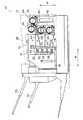
図1には、本発明の実施形態に係る無線通信システムを備えたレーザープリンターが示されている。このレーザープリンター10は、公知の電子写真プロセスにより、外部装置から入力した画像情報に基づいて画像(トナー像)を形成し、この画像を記録紙等に記録するものである。ここで、電子写真プロセスとは、電子写真感光体に対する帯電、レーザー露光による静電潜像の形成、トナーによる静電潜像の現像を経て電子者写真感光体上に形成されたトナー像を記録材に転写し、これを加熱定着することで記録材に画像を記録する一連のプロセスを言い、この電子写真プロセス及び電子写真プロセスに直接的に関係する電子写真感光体等の各種部品(プロセス部品)のうち、本発明の本質とは直接関係しないものについては、詳細な説明を省略する。なお、本実施形態に係るレーザープリンター10は、マゼンタ(M)、イエロー(Y)、クロ(K)及びシアン(C)のトナーを用いてカラー画像の形成が可能とされたものである。
【0024】
レーザープリンター10には、装置の外殻部として筐体12が設けられており、この筐体12内には、装置を構成する各種部品を支持するためのメインフレーム14が設けられている。メインフレーム14には、装置の幅方向(矢印W方向)に沿った一端部(図1では左端部)にプロセスユニット16が配置されている。このプロセスユニット16には、メインフレーム14により装置の奥行方向に沿ってスライド可能に支持されたスライドフレーム18が設けられており、このスライドフレーム18には、中間転写ベルト、転写器、クリーニング器等の所定のプロセス部品(図示省略)が搭載されている。これにより、メンテナンス時には、プロセスユニット16をメインフレーム14内から外部へ引き出し、スライドフレーム18に搭載されたプロセス部品の交換、点検作業等の簡略化が図れている。
【0025】
メインフレーム14には、プロセスユニット16に隣接するように4個の感光体ドラム20,22,24,26が支持されると共に、これらの感光体ドラム20,22,24,26にそれぞれ接するように4台の現像器21,23,25,27が配置されている。これら4台の現像器21,23,25,27は、それぞれマゼンタ(M)、イエロー(Y)、クロ(K)及びシアン(C)のトナーに対応しており、感光体ドラム20,22,24,26の外周面(像担持面)に形成された静電潜像をKトナー、Mトナー、Yトナー及びCトナーによりそれぞれトナー像として現像する。
【0026】
4個の感光体ドラム20,22,24,26にそれぞれ形成されたトナー像は、プロセスユニット16側に配置された中間転写ベルト上に転写、重畳されてフルカラーのトナー像を形成する。このフルカラーのトナー像は、中間転写ベルトから記録紙等の記録材へ転写された後、加熱定着され記録材に記録される。またレーザープリンター10では、Kトナーのみで形成されたモノクロのトナー像を記録材へ記録することも可能とされている。トナー像が記録された記録材は、所定の搬送経路(図示省略)に沿って搬送され、筐体12の上面部に形成された排紙トレー部28上又は、筐体12の側面部に側方へ延出するように取り付けられた排紙トレー30,32上へ排紙される。
【0027】
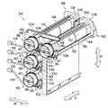
レーザープリンター10には、幅方向に沿ってメインフレーム14に隣接するようにカートリッジホルダ34が設けられている。このカートリッジホルダ34には、図2に示されるように、それぞれ略円柱状に形成された4個のトナーカートリッジ36,38,40,42が着脱可能に装着されている。これらのトナーカートリッジ36,38,40,42内には、内部にそれぞれ異なる色のトナー(マゼンタ(M)トナー、イエロー(Y)トナー、クロ(K)トナー及びシアン(C)トナー)が充填されている。
【0028】
図1に示されるように、筐体12には、片側(図1の紙面手前側)の側面部にプロセスユニット16及びカートリッジホルダ34に対向してメンテナンス用の開閉扉13が開閉可能に設けられている。これにより、ユーザ等は、開閉扉13を開放し、プロセスユニット16及びカートリッジホルダ34を外部に露出させることで、プロセスユニット16をメインフレーム14内から外側へ引き出し、またカートリッジホルダ34に対してトナーカートリッジ36,38,40,42をそれぞれ着脱することが可能になる。
【0029】
カートリッジホルダ34に装着されたトナーカートリッジ36,38,40,42はトナーを一時的に収容するための容器として構成されている。すなわち、レーザープリンター10では、現像器21,23,25,27の作動時に、トナーカートリッジ36,38,40,42内からトナーを排出させ、このトナーを現像器21,23,25,27に供給し、またトナーカートリッジ36,38,40,42内に充填された使用可能なトナーが全て排出されると、そのトナーカートリッジ36,38,40,42が新しいものに交換される。このとき、トナーがトナーカートリッジ36,38,40,42内に密封されていることから、レーザープリンター10に対するトナー補給を簡単な作業で行え、またトナー補給時におけるトナー飛散による装置内外の汚染も効果的に防止できる。
【0030】
図2に示されるように、トナーカートリッジ36,38,40,42は、樹脂材料により薄肉円筒状に成形された筒体44を備えている。この筒体44には、軸方向に沿った一端面(後端面)に内部に連通する開閉口49(図7参照)が設けられている。筒体44の開閉口49は、円筒状に形成された樹脂製の閉塞栓46により閉塞されている。閉塞栓46は、その一端部に先端へ向って縮径するテーパ部46A(図7参照)が形成されており、このテーパ部46Aが開閉口49を通して筒体44内へ圧入されている。また閉塞栓46には、その内周側が円板状の底板部45により塞がれており、閉塞栓46内には、底板部47の外側にプレート状の把手部48が一体的に成形されている。
【0031】
図3及び図4に示されるように、筒体44の先端部には、その周壁部の内周側に断面が略矩形状とされた内周筒部50が一体的に設けられており、この内周筒部50の底板部には、円板状の従動連結板52が筒体44の軸心Sを中心として回転可能に設置されている。従動連結板52の表面側には、周方向に沿って複数の噛合爪53が一体的に形成されている。一方、筒体44内には、ねじ軸状に形成されたトナー搬送用のスクリューフィーダ(図示省略)が同軸的に軸支されており、このスクリューフィーダは従動連結板52に連結され、この従動連結板52と一体となって回転する。
【0032】
図4に示されるように、筒体44の周壁部には、その先端側にトナー供給口54及びトナー充填口55がそれぞれ形成されており、トナー供給口54の外周側には、図9及び図10に示されるように、周方向に沿ってスライド可能とされたプレート状のシャッター部材56が配置されている。シャッター部材56は、トナー供給口54を閉塞する閉塞位置(図9参照)とトナー供給口54を開放する開放位置(図10参照)との間でスライド可能とされており、コイルスプリング等の付勢部材(図示省略)により常に閉塞位置に付勢されている。これにより、シャッター部材56は、トナーカートリッジ36,38,40,42がカートリッジホルダ34に装着されていない状態では、閉塞位置に保持される。また筒体44の周壁部にはトナー充填口55の外周側にキャップ部材58が固着されてトナー充填口55が閉塞されている。
【0033】
また、図8及び図9に示されるように、筒体44の先端部における外周側には、薄肉円筒状のスライドカバー57が軸方向に沿ってスライド可能に配置されている。このスライドカバー57は、シャッター部材56及びキャップ部材58を外周側から覆うカバー位置(図8参照)とシャッター部材56及びキャップ部材58に対して閉塞栓46側へスライドした待機位置(図9参照)との間でスライド可能とされており、コイルスプリング等の付勢部材(図示省略)により常にカバー位置に付勢されている。これにより、スライドカバー57は、トナーカートリッジ36,38,40,42がカートリッジホルダ34に装着されていない状態では、カバー位置に保持される。なお、図3、図7、図8、図9及び図10以外の各図では、説明の簡略化のためにスライドカバー57を省略した状態で、各トナーカートリッジ36,38,40,42が示されている。
【0034】
図4に示されるように、筒体44の後端部には、その周壁部の内周面と内周筒部50の外周面との間に形成される空間内に周壁部と内周筒部50とを連結するように4枚の仕切板60,61,62,63がリブ状に形成されている。これらの仕切板60,61,62,63は、筒体44における周壁部と内周筒部50との間に形成される環状の空間を周方向に沿って小空間に区画している。これらの小空間は、筒体44の先端面へ開口すると共に、後端側が筒体44の底板部45により閉塞されている。
【0035】
ここで、筒体44内における仕切板60と仕切板61との間の小空間及び仕切板61と仕切板62との間にの小空間は、それぞれ後述する1個の無線通信タグ72(図4参照)を収納するための収納室64,66として構成されている。また仕切板60と仕切板63との間の小空間も、1個の無線通信タグ72を収納する収納室68として構成されているが、この収納室68は、図5に示されるように、内周筒部50のエッジ部50A付近を境として機能的には収納部68Aと収納部68Bとに分割されており、収納室68では、2個の収納部68A,68Bの何れかに選択的に無線通信タグ72が収納可能とされている。従って、1個の無線通信タグ72は、収納室64、収納室66及び収納室68における2個の収納部68A,68Bの何れかに選択的に収納され、この選択された収納室64,66及び収納部68A,68Bに応じて取付位置が周方向に沿って変化する。
【0036】
図4に示されるように、無線通信タグ72は、軸方向から見た投影形状が収納室64,66に対応する略扇状とされており、収納室64、収納室66、収納室68における収納部68A,68Bの何れかに嵌挿されることで、その収納室64,66及び収納部68A,68Bの何れかの内部に収納、保持される。無線通信タグ72には、外周面における挿入側の端部に外周側に突出する一対の掛止爪74が形成され、さらに入口側の端面部に軸心S側へ突出する係合突起76が形成されている。一方、筒体44の周壁部には、無線通信タグ72における掛止爪74に対応する掛止穴78が収納室64,66及び収納部68A,68B毎に形成されており、内周筒部50の後端面には、無線通信タグ72における係合突起76に対応するノッチ状の係合凹部80が収納室64,66及び収納部68A,68B毎に形成されている。
【0037】
従って、無線通信タグ72は、収納室64,66及び収納部68A,68Bの何れかに嵌挿されると、その外周面を筒体44の内周面に密着させた状態となって、一対の掛止爪74をそれぞれ一対の掛止穴78に挿入すると共に、係合突起76を係合凹部80に係合させる。これにより、軸方向に沿った移動が確実に拘束され、かつ係合突起76を係合凹部80に係合することで周方向に沿ったガタツキも防止される。この収納室64,66,68内に嵌挿された無線通信タグ72は、専用の治具等により一対の掛止爪74を内周側に弾性変形させつつ、外側へ引き抜くことにより、筒体44から取り外せるようになっている。
【0038】
図4に示されるように、無線通信タグ72内には、銅線等の導電性線材がコイル状に巻き巻かれて構成されたタグ側アンテナ82が設けられている。タグ側アンテナ82は、その導電性線材の巻中心であるコイル軸TCが無線通信タグ72の厚さ方向と略平行となるように設けられ、また軸直角方向に沿ったコイル面の形状が無線通信タグ72の外周面に沿って湾曲している。具体的には、無線通信タグ72には、図5及び図6に示されるように、互いに平行となるように湾曲した外壁部84と内壁部86とが設けられ、これらの外壁部84と内壁部86との間を巻芯部88が連結している。この巻芯部88の外周側に導電性線材が巻かれることにより、軸方向に沿って扁平なタグ側アンテナ82が無線通信タグ72の外周面に沿って湾曲するように構成されている。
【0039】
また無線通信タグ72には、タグ側アンテナ82の内周側には外部から密閉された隔室部90が設けられている。隔室部90内には回路基板92が納められており、この回路基板92上には無線通信タグ72の制御回路が1チップとして集積されたICチップ94が実装されている。ICチップ94は、回路基板92等を介してタグ側アンテナ82に電気的に接続されている。
【0040】
図2に示されるように、装置本体側に設けられたカートリッジホルダ34には、装置の高さ方向(矢印H方向)に沿って上段部に2個のカートリッジ装着部96,98が、中段部及び下段部にそれぞれ1個ずつカートリッジ装着部100,102が設けられており、これらのカートリッジ装着部96,98,100,102には、それぞれ1個のトナーカートリッジ36,38,40,42が着脱可能に装着される。ここで、カートリッジホルダ34に装着された4個のトナーカートリッジ36,38,40,42は、その軸方向外側から見て逆L字状の配列となっており、これにより、4個のトナーカートリッジ36,38,40,42が高さ方向に沿って直線状に配列された場合と比較し、装置の高さ方向への寸法増加が抑制されている。
【0041】
図2に示されるように、カートリッジホルダ34には、装置奥側の端部に4個のトナーカートリッジ36,38,40,42のそれぞれ装着位置に対応するように4個(図2では上段部の2個のみが示されている。)の駆動ユニット108が設けられている。これらの駆動ユニット108は、それぞれ外形形状が肉厚板状とされており、その厚さ方向が装置の奥行方向と一致するように支持されている。駆動ユニット108には、トナーカートリッジ36,38,40,42の先端面に対向する表面部にトナーカートリッジ36,38,40,42の従動連結板52(図4参照)に対応する駆動連結板(図示省略)が回転可能に配置されている。この駆動連結板は、基本的には従動連結板52と対称的な形状とされており、従動連結板52と噛合可能とされている。また駆動ユニット108内には、それぞれ駆動モータ(図示省略)が内蔵されており、この駆動モータは現像器21,23,25,27の作動時に回転して駆動連結板を回転させる。
【0042】
図2に示されるように、カートリッジホルダ34には、装置手前側の端部に4個のトナーカートリッジ36,38,40,42を囲うように逆L字状に延在する支持プレート104が設けられており、この支持プレート104には、4個のトナーカートリッジ36,38,40,42のそれぞれ装着位置に対応するように4個の支持ブラケット106が連結固定されている。カートリッジホルダ34に装着された4個のトナーカートリッジ36,38,40,42は、カートリッジホルダ34に装着された状態では、駆動ユニット108と支持ブラケット106との間に掛け渡され、これらの駆動ユニット108及び支持ブラケット106により先端部及び後端部が支持される。また支持ブラケット106には、トナーカートリッジ36,38,40,42のシャッター部材56及びスライドカバー57にそれぞれ係合可能とされたシャッター係合部及びカバー係合部(図示省略)が設けられている。
【0043】
図2に示されるように、カートリッジホルダ34の各カートリッジ装着部96,98,100,102には、駆動ユニット108と支持ブラケット106との間に2個のガイド部材110,112が奥行方向へ延在するように掛け渡されており、トナーカートリッジ36,38,40,42は、カートリッジホルダ34に対する挿脱時には、ガイド部材110,112により奥行方向に沿って直線的に移動するように案内される。
【0044】
レーザープリンター10において、トナーカートリッジ36,38,40,42をカートリッジホルダ34における対応するカートリッジ装着部96,98,100,102に装着する際には、先ず、トナーカートリッジ36,38,40,42を奥行方向に沿って装置奥側へ挿入し、トナーカートリッジ36,38,40,42の先端部を駆動ユニット108に突き当てる。これにより、トナーカートリッジ36,38,40,42の先端部が駆動ユニット108に連結され、また支持ブラケット106のシャッター係合部がトナーカートリッジ36,38,40,42のシャッター部材56に係合する。このトナーカートリッジ36,38,40,42のカートリッジホルダ34への挿入動作に連動し、支持ブラケット106のカバー係合部がスライドカバー57に係合し、スライドカバー57をカバー位置から待機位置へスライドさせる。
【0045】
次いで、把手部48を用いてトナーカートリッジ36,38,40,42を時計方向へ所定角度だけ回転させることで、トナーカートリッジ36,38,40,42がカートリッジ装着部96,98,100,102に装着完了する。このとき、駆動ユニット108に配置された駆動連結板がトナーカートリッジ36,38,40,42の従動連結板52に噛み合い、駆動ユニット108に内蔵された駆動モータが、駆動連結板及び従動連結板52を介してトナーカートリッジ36,38,40,42内のスクリューフィーダへトルク伝達可能に連結される。またトナーカートリッジ36,38,40,42のカートリッジ装着部96,98,100,102での回転に連動し、支持ブラケット106のシャッター係合部がシャッター部材56に係合し、シャッター部材56を閉塞位置から開放位置へスライドさせる。これにより、トナー供給口54が開放してトナーカートリッジ36,38,40,42内に充填されたトナーがトナー供給口54を通して排出可能になる。
【0046】
図2に示されるように、レーザープリンター10には、カートリッジホルダ34における各カートリッジ装着部96,98,100,102と現像器21,23,25,27との間にトナー給送管114が配設されている。このトナー給送管114の一端部は支持ブラケット106に接続されており、トナーカートリッジ36,38,40,42がカートリッジ装着部96,98,100,102に装着されると、支持ブラケット106を介してトナーカートリッジ36,38,40,42のトナー供給口54に接続される。またトナー給送管114内には、トナー搬送用のスクリューフィーダ(図示省略)が配置されており、このスクリューフィーダには、トルク伝達軸116等を介して駆動ユニット108内の駆動モータからのトルクが伝達される。
【0047】
レーザープリンター10では、現像器21,23,25,27の作動時に、作動している現像器21,23,25,27に対応する駆動ユニット108に内蔵された駆動モータを回転させる。これにより、トナーカートリッジ36,38,40,42は、スクリューフィーダの作用によりトナー供給口54からトナーが所定速度で排出され、このトナーがトナー給送管114を通して作動状態にある現像器21,23,25,27に供給される。このとき、現像器21,23,25,27に供給されるトナー量は、現像のために消費されるトナーの量と略等しくなるように制御される。
【0048】
図3に示されるように、カートリッジホルダ34には、カートリッジ装着部96,98間における装置奥側及びカートリッジ装着部100,102間における装置奥側にそれぞれプレート状のアンテナユニット118,120が設置されている。これらのアンテナユニット118,120には、それぞれ樹脂により薄肉プレート状に成形されたケーシング部122が設けられると共に、このケーシング部122内に銅線等の導電性線材が巻き回されたコイル状の本体側アンテナ124が配置されている。アンテナユニット118,120は、そのコイル軸BC(図5参照)がケーシング部122の厚さ方向と平行となり、かつ軸直角方向に沿った表裏面(コイル面)がケーシング部122の面方向と平行になっている。ここで、カートリッジホルダ34における上段部に配置されたアンテナユニット118は、その軸方向に直交する面方向が装置の幅方向(矢印W方向)と略直交するように支持され、中段部と下段部との間に配置されたアンテナユニット120は、その面方向が装置の高さ方向(矢印H方向)と略直交するように支持されている。
【0049】
図3に示されるように、カートリッジホルダ34にトナーカートリッジ36,38,40,42が装着された状態では、上側のアンテナユニット118は、装置の幅方向に沿ってトナーカートリッジ36,38間に形成される隙間に挿入されるように支持され、また下側のアンテナユニット120は、装置の高さ方向に沿ってトナーカートリッジ40,42間に形成される隙間に挿入されるように支持される。
【0050】
一方、カートリッジホルダ34におけるカートリッジ装着部96に装着されたトナーカートリッジ36には、収納室68における収納部68A内に無線通信タグ72が嵌挿され、カートリッジ装着部98に装着されたトナーカートリッジ38には収納室64に無線通信タグ72が嵌挿されている。これにより、トナーカートリッジ36におけるタグ側アンテナ82は、そのコイル面を本体側アンテナ124の厚さ方向に沿った一方のコイル面に十分に近接させつつ正対させ、またトナーカートリッジ38におけるタグ側アンテナ82は、そのコイル面を本体側アンテナ124の厚さ方向に沿った他方のコイル面に十分に近接させつつ対向させる。
【0051】
また、カートリッジホルダ34におけるカートリッジ装着部100に装着されたトナーカートリッジ40には、収納室66内に無線通信タグ72が嵌挿され、カートリッジ装着部102に装着されたトナーカートリッジ42には収納室68における収納部68B内に無線通信タグ72が嵌挿されている。これにより、トナーカートリッジ40におけるタグ側アンテナ82は、そのコイル面を本体側アンテナ124の上面側のコイル面に十分に近接させつつ正対させ、またトナーカートリッジ42におけるタグ側アンテナ82は、そのコイル面を本体側アンテナ124の下面側のコイル面に十分に近接させつつ正対させる。
【0052】
ここで、タグ側アンテナ82と本体側アンテナ124との電波送受信は、通常、アンテナ間の距離が短いほど効率が良くなり、またタグ側アンテナ82と本体側アンテナ124とが平行な位置関係に近づくほど効率が良くなる。レーザープリンター10では、トナーカートリッジ38,40,42に取り付けられたタグ側アンテナ82については、本体側アンテナ124と平行に支持されており、アンテナ間の距離が一定の条件下では、略最高効率で本体側アンテナ124との電波送受信が可能になっている。またトナーカートリッジ36に取り付けられたタグ側アンテナ82については、本体側アンテナ124に一定角度(約20°)傾いて支持されているが、本体側アンテナ124との距離が十分に小さいことから、十分に高い効率で電波送受信が可能になっている。これを換言すれば、無線通信タグ72と本体側の無線通信装置130(図11参照)との間で使用される電波出力を十分に小さくすれば、一方の本体側アンテナ124と、この本体側アンテナ124とは通信関係が設定されている無線通信タグ72との間における良好な通信状態を維持しつつ、一方の本体側アンテナ124と、この本体側アンテナ124とは通信関係が設定されていない無線通信タグ72との混信が確実に防止できる。
【0053】
また、トナーカートリッジ36,38,40,42がカートリッジ装着部96,98,100,102に不完全に装着されている場合には、タグ側アンテナ82と本体側アンテナ124との距離が設計上の設定値よりも長くなるため、無線通信装置130と不完全に装着されたトナーカートリッジ36,38,40,42の無線通信タグ72との通信が正常には行えなくなる。従って、無線通信装置130が何れかのトナーカートリッジ36,38,40,42の無線通信タグ72との通信が正常に行えない場合には、これに対応するアラーム信号を中央制御部等へ出力し、中央制御部等によりトナーカートリッジの装着が不完全であることをユーザへ報知するための制御を行っても良い。
【0054】
図8に示されるように、各トナーカートリッジ36,38,40,42における筒体44には、製造段階において、その外周面に4個の識別キー44A,44B,44C,44Dが一体的に成形されている。これらの識別キー44A,44B,44C,44Dは、それぞれ軸方向へ細長い突起状に形成されており、筒体44の下部側に周方向に沿って一定ピッチで配列されている。ここで、これら4個の識別キー44A,44B,44C,44Dは、トナーカートリッジ36,38,40,42内に収容される4種類のトナー(Mトナー、Yトナー、Kトナー及びCトナー)にそれぞれ対応して設けられており、ある種類(色)のトナーを収容するトナーカートリッジ36,38,40,42を組み立てる際に、収容トナー以外のトナーに対応する3個の識別キー44A,44B,44C,44Dは筒体44から除去され、収容するトナーに対応する1個の識別キー44A,44B,44C,44Dのみが筒体44に残される。
【0055】
なお、識別キー44A,44B,44C,44Dは、例えば、根元部を加熱しつつ剪断力を加えることで筒体44から除去される。また、筒体44に識別キー44A,44B,44C,44Dを一体成形する代わりに、筒体44に少なくとも識別キーを取り付けるための4個以上のキー取付部を形成し、このキー取付部の何れかにプレート状の識別キーを嵌挿、接着等により固定し、筒体44におけるトナーに対応する位置に識別キーを取り付けるようにしても良い。
【0056】
一方、図5に示されるように、カートリッジホルダ34の各カートリッジ装着部96,98,100,102には、下部側のガイド部材112(図5には、カートリッジ装着部100,102のガイド部材112のみが示されている。)にそれぞれ4個の識別キー44A,44B,44C,44Dの何れかに対応する部位にスリット状の係合溝113が形成されている。これらの係合溝113は、装置の奥行方向に沿ってガイド部材112の支持プレート104側の一端から中央付近まで延在している。これにより、各カートリッジ装着部96,98,100,102にトナーカートリッジ36,38,40,42を装着する際に、カートリッジ装着部96,98,100,102に所定種類のトナーを収容した適正なトナーカートリッジ36,38,40,42が装着される場合にのみ、その識別キー44A,44B,44C,44Dが係合溝113を通って装置奥側へ移動可能になり、カートリッジ装着部96,98,100,102に所定種類以外のトナーを収容した不適正なトナーカートリッジ36,38,40,42を装着しようとした場合には、識別キー44A,44B,44C,44Dがガイド部材112の端面に衝突して装置奥側への移動が阻止される。
【0057】
従って、ユーザが誤って不適正なトナーカートリッジ36,38,40,42をカートリッジ装着部96,98,100,102に装着しようとした場合には、トナーカートリッジ36,38,40,42のカートリッジ装着部96,98,100,102への挿入が阻止されるので、トナーカートリッジ36,38,40,42のカートリッジ装着部96,98,100,102への誤装着が確実に防止される。
【0058】
なお、トナーカートリッジ36,38,40,42にそれぞれ識別キー44A,44B,44C,44Dを設ける代わりに、軸方向へ延在するカートリッジ識別溝を、トナー種類毎に異なる部位に形成すると共に、各カートリッジ装着部96,98,100,102におけるガイド部材112にそれぞれカートリッジ識別溝に対応する突起部を設けるようにしても良い。
【0059】
また、各トナーカートリッジ36,38,40,42にそれぞれカートリッジ識別部を設けると共に、各カートリッジ装着部96,98,100,102にそれぞれ前記カートリッジ識別部の形状、位置等を検出してトナーカートリッジ36,38,40,42の種類を識別するメカニカルセンサー、前記カートリッジ識別部に記録されたカートリッジ種類に対応する情報を光学的、磁気的又は機械的に読み取って装着されたトナーカートリッジ36,38,40,42の種類を識別する情報読取用センサーを設けるようにしても良い。これにより、レーザープリンター10の中央制御部等が、メカニカルセンサー又は情報読取用センサーからの信号に基づいて装着されたトナーカートリッジ36,38,40,42の正誤を判断し、誤ったトナーカートリッジ36,38,40,42が装着されている場合には、例えば、装置動作のインターロック、ユーザへのアラーム信号の出力等の制御を実行できる。
【0060】
(無線通信システムの構成及び動作)
次に、上記のように構成された本実施形態に係る無線通信システムを備えたレーザープリンターの構成及び動作について説明する。
【0061】
図11には、本実施形態に係る無線通信システムの構成がブロック図として示されている。この無線通信システム128は、4個のトナーカートリッジ36,38,40,42にそれぞれ取り付けられた無線通信タグ72及び装置本体側に配置された無線通信装置130により構成されている。無線通信装置130は、カートリッジホルダ34に配置された2個のアンテナユニット118,120及び、これらのアンテナユニット118,120にそれぞれ接続された本体部132を備えている。
【0062】
前述したように、各トナーカートリッジ36,38,40,42に取り付けられる無線通信タグ72は、コイル上のタグ側アンテナ82及び回路基板92上に実装されたICチップ94を備えている。ICチップ94には、図11に示されるように、CPU134、送受信回路136、電源回路138、ROM140及びEEPROM142が集積された単一素子として構成されている。CPU134は、ROM140に格納された制御プログラムに従って無線通信タグ72全体を制御する。またROM140には、制御プログラムに加えて、トナーカートリッジ36,38,40,42の種類に応じた固有の情報としてマルチID、パスワード及びシステムIDが格納されている。ここで、マルチIDとは、基本的にトナーカートリッジ36,38,40,42の種類に対応して付与されたデータであり、またパスワード及びシステムIDは、それぞれ無線通信装置130との情報交換を許可された無線通信タグ72であることを確認するためのデータである。
【0063】
一方、EEPROM142は、記憶情報を維持するための電力が不要とされた不揮発性の情報記憶素子であり、CPU134により任意の情報を書き込むと共に、書き込まれた情報から任意のものを読み出すことが可能とされている。具体的には、EEPROM142には、例えば、CPU134により下記のような情報が書き込まれ、必要に応じて書き込まれた情報の内容が更新される。
【0064】
▲1▼ 感光体ドラム20,22,24,26に対する露光量、帯電量、現像バイアス等のプロセス情報
▲2▼ トナーカートリッジ36,38,40,42についてのロット番号、製造日、種類、保存期間、認識番号、リサイクル回数、リサイクル回数の上限値、カートリッジの構成部品の交換時期
▲3▼ トナーについてのロット番号、製造日、充填量、種類、保存期間、リサイクル回数、リサイクル回数の上限値
無線通信タグ72における送受信回路136は、情報送信時には、CPU134から送られてきたパラレルの情報信号をシリアルの情報信号に変換した後、この情報信号により変調された電気信号をタグ側アンテナ82へ出力する。これにより、タグ側アンテナ82からは、CPU134からの情報信号に対応する電波信号が出力される。また送受信回路136は、情報受信時には、タグ側アンテナ82により受信した電波信号により得られた電気信号をシリアルの情報信号に復調した後、この情報信号をパラレルの情報信号に変換してCPU134に出力する。
【0065】
無線通信タグ72における電源回路138は、無線通信装置130との送受信時に、タグ側アンテナ82に電磁誘導により生じた所定周波数の交流電流を情報信号から分離し、この交流電流を直流電流に変換した後、CPU134及び送受信回路136に供給する。これにより、CPU134及び送受信回路136には、無線通信装置130との送受信時に必要な電力が供給され、無線通信タグ72には電池、バッテリ等の電源が不要とされている。
【0066】
図11に示されるように、無線通信装置130の本体部には、CPU144、送受信回路146、電源回路148、ROM150、RAM152及びインターフェイス回路154が設けられている。ここで、送受信回路146は、アンテナに対して2個の入出力端子146A,146Bを備えており、一方の入出力端子146Aにはアンテナユニット118の本体側アンテナ124が接続され、他方の入出力端子146Bにはアンテナユニット120の本体側アンテナ124が接続されている。送受信回路146は、無線通信タグ72との情報送受信時に、情報の入出力先に応じて入出力端子146A,146Bの一方のみをオン状態とし、他方をオフ状態とする。
【0067】
CPU144は、ROM150に格納された制御プログラムに従って無線通信装置130全体を制御する。またROM150には、制御プログラムに加えて、全てのトナーカートリッジ36,38,40,42についてのマルチID、パスワード及びシステムIDが格納されている。CPU144は、無線通信タグ72から入力したマルチID及びパスワードをROM150に格納されたマルチID及びパスワードと比較することで、電波通信中の無線通信タグ72が取り付けられているトナーカートリッジ36,38,40,42の種類を識別すると共に、無線通信装置130との情報交換を許可された無線通信タグ72であることを確認する。
【0068】
CPU144は、インターフェイス回路154を通してレーザープリンター10の中央制御部(図示省略)から送られてきた各トナーカートリッジ36,38,40,42毎の感光体ドラム20,22,24,26に対する露光量、帯電量、現像バイアス等のプロセス情報、このプロセス情報に基づいて演算されるトナー消費量等の書き込み情報をRAM152に一時記憶させた後、所定のタイミングでRAM152から送信情報を読み出し、無線通信タグ72へ送信する。これにより、無線通信タグ72のCPU134は、無線通信装置130から受信した書き込み情報をEEPROM142に書き込み、トナーの充填量から消費量を減算したトナー残量をEEPROM142に記録する。
【0069】
本体部132における送受信回路146は、情報送信時には、CPU144から送られてきたパラレルの情報信号をシリアルの情報信号に変換した後、この情報信号により変調された電気信号を2個の本体側アンテナ124の何れかに出力する。これにより、本体側アンテナ124からは、CPU144からの情報信号に対応する電波信号が出力される。また送受信回路146は、情報受信時には、本体側アンテナ124により受信した電波により得られた電気信号をシリアルの情報信号に復調した後、この情報信号をパラレルの情報信号に変換してCPU144に出力する。
【0070】
本体部における電源回路148は、無線通信タグ72との交信中に所定周波数の交流電流を本体側アンテナ124に供給する。これにより、この本体側アンテナ124に対向するタグ側アンテナ82には電磁誘導が生じ、前述したように、無線通信タグ72に誘導電流(電力)が供給される。ここで、電源回路148により本体側アンテナ124に供給される交流電流の周波数は、送受信回路136,146により情報伝送用に用いられる電気信号の周波数と送信時は同じ帯域が選択され、受信時は異なる帯域(例えば、高周波域)が選択されている。
【0071】
また本体部132のCPU144は、トナーカートリッジ36,38,40,42内から全てのトナーが排出されたことを判断した時点で、そのトナーカートリッジ36,38,40,42に取り付けられた無線通信タグ72にカウントアップ信号を送信する。このカウントアップ信号を受けた無線通信タグ72のCPU134は、EEPROM142に書き込まれているトナーカートリッジ36,38,40,42についてのリサイクル回数及びトナーについてのリサイクル回数に“1”を加算する。
【0072】
図15には、本実施形態に係る無線通信システム128における通信開始処理の一連の動作が示されている。レーザープリンター10では、電源投入、トナーカートリッジ36,38,40,42の交換、ジャム等の異常発生後のリセット処理等が行われた場合に、無線通信装置130のCPU144により図15に示される無線通信システム128の通信開始処理を行う。
【0073】
なお、無線通信システム128において、無線通信装置130との通信が行われる通信先は、正確には各トナーカートリッジ36,38,40,42に取り付けられ無線通信タグ72であるが、以下の図15のフローチャートに係る記載では、通信先を正確に区別する必要ない場合は、説明を簡略化するため無線通信装置130の通信先を単に「トナーカートリッジ36、トナーカートリッジ38、トナーカートリッジ40又はトナーカートリッジ42」と記載する。
【0074】
通信開始処理では、ステップ300にて、無線通信装置130側のマルチID(M)とトナーカートリッジ36側のマルチID(M)とが一致しているか否を判断する。ステップ300で、無線通信装置130側のマルチID(M)とトナーカートリッジ36側のマルチID(M)とが一致した場合、カートリッジホルダ34のカートリッジ装着部96に適正なトナーカートリッジ36が装着されていると判断し、ルーチンをステップ304へ移行し、無線通信装置130がトナーカートリッジ36との通信を開始する。また無線通信装置130側のマルチID(M)とトナーカートリッジ36側のマルチID(M)が一致しない場合には、ルーチンをステップ302へ移行し、カートリッジホルダ34のカートリッジ装着部96にトナーカートリッジが正常に装着されていないか、又はカートリッジ装着部96に装着されているトナーカートリッジが不適正なものであると判断し、所定のエラー処理を実行する。
【0075】
ステップ304〜306で、無線通信装置130とトナーカートリッジ36との間で、パスワード照合及びシステムID照合を順に行う。このとき、トナーカートリッジ36側のパスワード及びシステムIDの何れかが登録されたものと一致しない場合には、カートリッジ装着部96に装着されているトナーカートリッジが不適正なものであると判断し、ルーチンをステップ308へ移行し、所定のエラー処理を実行する。またトナーカートリッジ36側のパスワード及びシステムIDの双方が登録されたものであると判断された場合には、ルーチンを310へ移行し、無線通信装置130のCPU144は、トナーカートリッジ36における無線通信タグ72を制御し、EEPROM142から感光体ドラム20,22,24,26に対する露光量、帯電量、現像バイアス等のプロセス情報及びトナーについての充填量、種類及び保存期間等のトナー情報を読み取る。
【0076】
ステップ312では、無線通信装置130におけるCPU144は、トナーカートリッジ36におけるCPU134との間で、EEPROM142から読み取った情報がEEPROM142に書き込まれている情報と一致しているか否かを判断するリードチェックを実行し、双方の情報が一致している場合には、ルーチンをステップ314へ移行し、また双方の情報が一致していない場合には、ルーチンをステップ310にリターンし、EEPROM142から読み取った情報がEEPROM142に書き込まれた情報と一致するまで、EEPROM142に対する情報の読み取り処理を繰り返す。
【0077】
ステップ314では、無線通信装置130のCPU144は、レーザープリンター10固有の識別番号、ユーザ固有の識別番号、トナーカートリッジ36の使用開始時間等の初期情報をトナーカートリッジ36における無線通信タグ72へ送信し、この初期情報を無線通信タグ72のEEPROM142に書き込む。ステップ316では、無線通信装置130におけるCPU144は、トナーカートリッジ36におけるCPU134との間で、送信した初期情報がEEPROM142に誤り無く書き込まれた否かを判断するライトチェックを実行し、双方の情報が一致している場合には、トナーカートリッジ36との通信開始処理を終了させる。また双方の初期情報が一致していない場合には、ルーチンをステップ314にリターンし、無線通信タグ72に送信した初期情報がEEPROM142に書き込まれた情報と一致するまで、EEPROM142に対する情報の書き込み処理を繰り返す。
【0078】
無線通信システム128では、上記したMトナーを収容したトナーカートリッジ36についての通信開始処理が完了したならば、他のY、K及びCのトナーを収容したトナーカートリッジ38,40,42との間でも、図15に示される一連の通信開始処理と基本的に同一の処理を順に実行する。レーザープリンター10の中央制御は、無線通信装置130と全てのトナーカートリッジ36,38,40,42との間の通信開始処理が終了した後、画像形成動作が開始可能となるようにインターロックを解除する。
【0079】
また中央制御部は、画像形成を1回行う毎に、又は画像形成を所定回数行う毎に、無線通信装置130におけるインターフェイス回路154を通して各トナーカートリッジ36,38,40,42に対応するプロセス情報、トナー消費量等に関する情報をCPU144に出力する。CPU144は、中央制御部からの情報を対応するトナーカートリッジ36,38,40,42の無線通信タグ72に送信すると共に、その無線通信タグ72のEEPROM142に中央制御部からの情報を書き込む。
【0080】
(実施形態の作用)
次に、上記のように構成された本発明の実施形態に係る無線通信システムを備えたレーザープリンターの作用について説明する。
【0081】
本実施形態に係る無線通信システム128を備えたレーザープリンター10では、トナーカートリッジ36,38,40,42における各カートリッジ装着部96,98,100,102に対応する複数の部位にそれぞれ無線通信タグ72が取付可能とされた収納室64,66及び収納部68A,68Bを設け、トナーカートリッジ36,38,40,42が装着されるカートリッジ装着部96,98,100,102に対応する収納室64,66及び収納部68A,68Bの何れかに無線通信タグ72を選択的に取り付けることにより、異なるトナーを収容するトナーカートリッジ36,38,40,42がそれぞれカートリッジ装着部96,98,100,102に装着された状態にて、各トナーカートリッジ36,38,40,42に取り付けられる各無線通信タグ72を、アンテナユニット118,120の本体側アンテナ124に対して略平行となり、かつ十分に近接するように位置調整ができるので、トナーカートリッジ36,38,40,42にそれぞれ取り付けられた無線通信タグ72と装置本体に配置された無線通信装置130との間の電波による通信及びICチップ94への電力供給を、タグ側アンテナ82及び本体側アンテナ124を介して安定して行える。
【0082】
また、無線通信システム128を備えたレーザープリンター10によれば、何れのカートリッジ装着部96,98,100,102に装着されるトナーカートリッジ36,38,40,42についても、その構造及び形状を共通化できるので、トナーカートリッジ36,38,40,42の製造コストを低減できると共に、使用後のトナーカートリッジ36,38,40,42のメーカ等におけるリサイクル作業も容易になる。
【0083】
また、レーザープリンター10から取り外された使用済みのトナーカートリッジ36,38,40,42は、多くの場合、メーカ等により回収されてリサイクルされる。この際、トナーカートリッジ36,38,40,42から無線通信タグ72が取り外され、この無線通信タグ72に記録されたデータ等が書き換えられた後、無線通信タグ72が未使用又はリサイクルされたトナーカートリッジに取り付けられる作業が行われる場合がある。このような場合にも、本実施形態の無線通信システム128では、専用の治具等を用いて無線通信タグ72の掛止爪74付近を内周側へ弾性変形させるだけで、無線通信タグ72をトナーカートリッジ36,38,40,42から容易に取り外せるので、無線通信タグ72単体でのリサイクル作業も容易に行える。
【0084】
但し、使用済みのトナーカートリッジ36,38,40,42がメーカ等の正規の業者ではなく不正規な業者により回収され、この不正規な業者によりトナーカートリッジ36,38,40,42のリサイクル作業が試みられる場合が想定される。このような不正規な業者によりリサイクルされたトナーカートリッジ36,38,40,42がレーザープリンター10に装着されると、装置故障や画質低下等の問題が生じるおそれがある。この問題の防止方法としては、例えば、不正規な業者により無線通信タグ72がトナーカートリッジ36,38,40,42から取り外されることを阻止することが有効である。
【0085】
そこで、トナーカートリッジ36,38,40,42の収納室44,46及び収納部48A,48Bに取り付けられた無線通信タグ72を、所定のプロセスに従って取外作業が行われる場合にのみ、収納室44,46及び収納部48A,48Bから損傷なく取り外し可能にすることが考えられる。これを実現する具体的な方法としては、例えば、無線通信タグ72の外殻部を所定の温度に加熱された時にのみ十分な弾性変形が得られる樹脂材料により成形し、無線通信タグ72を取り外す際には、無線通信タグ72の掛止爪74付近を所定の温度に加熱しつつ、内周側へ弾性変形させなければ、無線通信タグ72が破壊されるようにすることが考えられる。また他の方法としては、無線通信タグ72にダイヤルロック機構、電磁式ロック機構等のロック機構を設け、無線通信タグ72に対して外部から所定のロック解除操作、又は所定のロック解除データを入力しなければ、ロック機構によるロック状態が解除されず、損傷なく無線通信タグ72を取り外せないようにすることも考えられる。
【0086】
(実施形態の変形例)
次に、本発明の実施形態に係る無線通信システムにおけるトナーカートリッジの第1及び第2の変形例について説明する。なお、これら変形例に係るトナーカートリッジは、それぞれ無線通信タグ72及びその取付部以外の部分については、既に説明したトナーカートリッジ36,38,40,42(図4参照)と共通構造とされている。このことから、これら変形例に係るトナーカートリッジでは、トナーカートリッジ36,38,40,42と構成及び作用が共通な部材に同一の符合を付して説明を省略する。
【0087】
図12には、本発明の実施形態に係る無線通信システムにおけるトナーカートリッジの第1の変形例が示されている。このトナーカートリッジ200には、筒体44の外周面にタグ貼付部202が設けられており、このタグ貼付部202には、それぞれ薄肉プレート状に形成された無線通信タグ204が貼付可能とされている。タグ貼付部202は、筒体44における従動連結板52が配置された側の端部(先端部)に配置され、筒体44の外周面における他の部分に対して所定長だけ小径とされて溝状になっている。また無線通信タグ204は、面方向に沿った形状が略長方形とされており、その長手方向が筒体44の周方向と一致するようにタグ貼付部202へ接着剤、粘着剤、両面テープ等からなる固着層を介して貼り付けられる。
【0088】
ここで、タグ貼付部202は、その軸方向に沿った幅が無線通信タグ204の短手方向に沿った幅よりも僅かに広くされ、また径方向に沿った深さが無線通信タグ72の厚さと略等しくされている。一方、無線通信タグ204は、例えば、樹脂等からなる2枚のシート材が積層された構造とされており、これらのシート材間には、コイル状にパターニングされた金属薄膜によりタグ側アンテナ206が設けられると共に、タグ側アンテナ206の中央部に薄膜状のICチップ208が配置されている。このICチップ208の内部構造は、図11に基づいて既に説明したICチップ94と基本的に共通なので説明を省略する。また無線通信タグ204は、長手方向に沿って湾曲可能となるように弾性を有しているか、或いは予めタグ貼付部202の底面部と略同一の曲率半径となるように長手方向に沿って予め湾曲されている。
【0089】
無線通信タグ204をトナーカートリッジ200のタグ貼付部202へ貼り付ける際には、無線通信タグ204の内周面に固着層を予め設けておき、この無線通信タグ204をタグ貼付部202内へ挿入し、固着層を介して無線通信タグ204の内周面全体をタグ貼付部202の底面部へ密着させる。この無線通信タグ204は、軸方向へはタグ貼付部202により精度良く所定位置へ位置決めされ、また軸心Sを中心とする周方向へは任意の位置へ位置調整することが可能になる。
【0090】
本実施形態に係る無線通信システム128に図12に示されたトナーカートリッジ200を適用した場合にも、トナーカートリッジ200におけるタグ貼付部202におけるカートリッジ装着部96,98,100,102に対応する部位に無線通信タグ204を選択的に貼り付けることにより、異なるトナーをそれぞれ収容する4個のトナーカートリッジ200がカートリッジ装着部96,98,100,102に装着された状態にて、各トナーカートリッジ200に貼り付けられた各無線通信タグ204を、アンテナユニット118,120の本体側アンテナ124に対して略平行となり、かつ十分に近接するようなに位置調整ができるので、4個のトナーカートリッジ200にそれぞれ取り付けられた無線通信タグ204と装置本体に配置された無線通信装置130との間の電波による通信及びICチップ208への電力供給を、タグ側アンテナ206及び本体側アンテナ124を介して安定して行える。
【0091】
また、カートリッジ装着部96,98,100,102にそれぞれ装着される各トナーカートリッジ200については、その構造及び形状を共通化できるので、トナーカートリッジ200の製造コストを低減できると共に、使用後のトナーカートリッジ200のメーカ等におけるリサイクル作業も容易になる。
【0092】
また、トナーカートリッジ200では、タグ貼付部202へ貼り付けられた無線通信タグ204がトナーカートリッジ200の表面部分に露出することから、無線通信タグ204と本体側アンテナ124との間にはトナーカートリッジ200の筒体44等の外殻部が介在しなくなる。この結果、トナーカートリッジ200の外殻部を金属等の電波遮蔽性を有する材料により形成した場合でも、無線通信タグ204と無線通信装置130との間の電波通信を良好に行える。
【0093】
なお、図12に示されるトナーカートリッジ200では、レーザープリンター10におけるカートリッジ装着部96,98,100,102の配置に対応して、タグ貼付部202を周方向へ延在するように設けたが、本実施形態とはカートリッジ装着部の配置が異なる画像形成装置へ適用される場合には、そのカートリッジ装着部の配置に応じて無線通信タグ204が貼り付けられるタグ取付部をトナーカートリッジ200における任意の部位へ設けることも可能であり、また特にタグ取付部を設けることなく、無線通信タグ204を筒体44外周面における任意の部位へ直接、貼り付けるようにしても良い。
【0094】
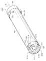
図13及び図14には、本発明の実施形態に係る無線通信システムにおけるトナーカートリッジの第2の変形例が示されている。このトナーカートリッジ210には、従動連結板52の外周側に周方向に沿って延在し、かつトナーカートリッジ210の先端面へ開口するタグ収納部212が設けられている。このタグ収納部212は、筒体44の先端側の周壁部214と、周壁部214の内周側に同軸的に設けられられた円筒部216との間に配置されており、軸心Sを中心とする一定の曲率半径を有する環状の空間として形成されている。
【0095】
一方、無線通信タグ218は、略長方形で厚さ一定のプレート状に形成されており、その長手方向に沿ってタグ収納部212と同一の曲率半径となるように湾曲されている。ここで、無線通信タグ218の厚さは、タグ収納部212の径方向に沿った幅よりも僅かに小さくなっている。無線通信タグ218内には、コイル状に巻かれた金属素線からなるタグ側アンテナ220が設けられると共に、タグ側アンテナ220の中央部にICチップ222が配置されている。このICチップ222の内部構造は、図11に基づいて既に説明したICチップ94と基本的に共通なので説明を省略する。
【0096】
無線通信タグ218は、その短手方向が軸心Sと平行な状態とされてタグ収納部212内へ収納されている。このとき、無線通信タグ218は、タグ収納部212と同一の曲率半径で湾曲していることから、タグ収納部212内で軸心Sを中心とする周方向へ周壁部214の内周面及び円筒部216の外周面に沿ってスライド(回動)可能に支持される。
【0097】
筒体44の周壁部214には、図13に示されように、周方向へ延在するスリット状の挿通溝224が穿設されている。この挿通溝224は、周方向に沿って不連続的に設けられており、少なくともカートリッジ装着部96,98,100,102にそれぞれ対応して部位を含むように設けられている。一方、無線通信タグ218には、図14に示されるように、挿通溝224に面して開口するネジ穴226が形成されている。
【0098】
タグ収納部212内へ挿入された無線通信タグ218を固定する際には、無線通信タグ218の周方向に沿ってカートリッジ装着部96,98,100,102の何れかに対応する位置へ位置調整した後、固定用のネジ穴228を、挿通溝224を通して無線通信タグ218のネジ穴226内へ捻じ込み、このネジ穴228を十分な締結トルクで締め込む。これにより、無線通信タグ218の外周面と周壁部214の内周面との間に十分に大きな摩擦力が生じて、無線通信タグ218がタグ収納部212内で確実に固定される。
【0099】
本実施形態に係る無線通信システム128に図13に示されたトナーカートリッジ210を適用した場合にも、トナーカートリッジ210におけるタグ収納部212内へ挿入された無線通信タグ218をカートリッジ装着部96,98,100,102に対応する位置へ選択的に位置調整し、ネジ228により締結固定することにより、異なるトナーをそれぞれ収容する4個のトナーカートリッジ210がカートリッジ装着部96,98,100,102に装着された状態にて、各トナーカートリッジ210に配置された各無線通信タグ218を、アンテナユニット118,120の本体側アンテナ124に対して略平行となり、かつ十分に近接するようなに位置調整ができるので、4個のトナーカートリッジ210にそれぞれ取り付けられた無線通信タグ218と装置本体に配置された無線通信装置130との間の電波による通信及びICチップ208への電力供給を、タグ側アンテナ220及び本体側アンテナ124を介して安定して行える。
【0100】
また、カートリッジ装着部96,98,100,102にそれぞれ装着される各トナーカートリッジ210については、その構造及び形状を共通化できるので、トナーカートリッジ210の製造コストを低減できると共に、使用後のトナーカートリッジ210のメーカ等におけるリサイクル作業も容易になる。さらに、無線通信タグ218では、ネジ穴228を緩めるだけだ無線通信タグ218が周方向へ位置調整可能になり、また無線通信タグ218をトナーカートリッジ210から取り外せるので、トナーカートリッジ36,38,40,42及びトナーカートリッジ200と比較してリサイクル作業を更に簡単に行える。
【0101】
なお、本実施形態では、本実施形態に係る無線通信システム128をレーザープリンター10における装置本体側の無線通信装置130とトナーカートリッジ36,38,40,42,200,210との間の交信に用いる場合のみを説明したが、このようなトナーカートリッジ以外にも、レーザープリンター10において装置本体に対して着脱される電子写真感光体及び1個以上のプロセス部品を含むプロセスユニット、電子写真感光体、クリーニング器、帯電器、除電器、現像器等のプロセス部品等に無線通信タグを取り付け、装置本体側の無線通信装置との間で電波による交信を行い、無線通信タグに対して各種のデータを書き込み、又は読み出すようにしても良い。
【0102】
また本実施形態に係る無線通信システムの基本構成は、レーザープリンター以外の各種の画像形成装置、例えば、電子写真プロセスを用いて画像形成を行うファクシミリ装置、プリンター、ファクシミリ等が一体となった複合機にも適用可能であり、さらに電子写真プロセスを用いることなく画像形成を行うインクジェットプリンタ、サーマルプリンター等の画像形成装置に適用し、インクカートリッジ、インクリボンカートリッジ等の装置本体に対して着脱されるカートリッジ部品に無線通信タグを取り付けるようにしても良い。
【0103】
【発明の効果】
以上説明したように、本発明に係る無線通信システム、画像形成装置及びカートリッジ部品によれば、装置本体における異なるカートリッジ装着部にそれぞれ装着されるカートリッジ部品におけるタグ取付部の構造及び形状を共通化し、しかもカートリッジ部品における無線通信タグを本体側アンテナに対して通信に適した位置へ簡単に位置調整できる。
【図面の簡単な説明】
【図1】 本発明の実施形態に係るレーザープリンターの構成を示す側面図である。
【図2】 図1に示されるレーザープリンターにおけるトナーカートリッジが着脱可能に装着されたカートリッジホルダの構成を示す斜視図である。
【図3】 図1に示されるレーザープリンターにおけるトナーカートリッジ及び無線通信装置のアンテナユニットの構成を示す斜視図である。
【図4】 図1に示されるレーザープリンターにおけるトナーカートリッジ及びトナーカートリッジに取り付けられる無線通信タグの構成を示す分解斜視図である。
【図5】 図1に示されるレーザープリンターにおけるトナーカートリッジに取り付けられた無線通信タグ及び無線通信装置のアンテナユニットを軸方向外側から見た正面図である。
【図6】 図1に示されるレーザープリンターにおけるトナーカートリッジに取り付けられた無線通信タグ及び無線通信装置のアンテナユニットを構成を示す側面断面図である。
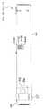
【図7】 本発明の実施形態に係る無線通信システムにおけるトナーカートリッジの一例を示す側面図であり、閉塞栓を筒体へ取り付ける前の状態を示している。
【図8】 本発明の実施形態に係る無線通信システムにおけるトナーカートリッジの一例を示す側面図であり、閉塞栓を筒体へ取り付けた状態を示している。
【図9】 本発明の実施形態に係る無線通信システムにおけるトナーカートリッジの一例を示す側面図であり、スライドカバーを待機位置へスライドさせた状態を示している。
【図10】 本発明の実施形態に係る無線通信システムにおけるトナーカートリッジの一例を示す側面図であり、開閉シャッターを開放位置へスライドさせた状態を示している。
【図11】 本発明の実施形態に係るレーザープリンターにおける無線通信システムの構成を示すブロック図である。
【図12】 本発明の実施形態に係る無線通信システムにおけるトナーカートリッジの第1の変形例を示す斜視図である。
【図13】 本発明の実施形態に係る無線通信システムにおけるトナーカートリッジの第2の変形例を示す斜視図である。
【図14】 図13に示すトナーカートリッジにおけるタグ収納部及び無線通信タグを示す断面図である。
【図15】 本発明の実施形態に係る無線通信システムによる通信開始処理時の動作を示すフローチャートである。
【符合の説明】
10 レーザープリンター(画像形成装置)
14 メインフレーム(装置本体)
34 カートリッジホルダ(カートリッジ装着部)
36、38、40、42、 トナーカートリッジ(カートリッジ部品 )
44A,44B,44C,44D 識別キー(カートリッジ識別部)
64 収納室(タグ取付部)
66 収納室(タグ取付部)
68 収納室(タグ取付部)
68A,68B 収納部(タグ取付部)
72 無線通信タグ
82 タグ側アンテナ
92 回路基板(タグ側無線制御部)
94 ICチップ(タグ側無線制御部)
96、98、100、102カートリッジ装着部
113 係合溝(カートリッジ識別手段)
118 アンテナユニット
120 アンテナユニット
124 本体側アンテナ
128 無線通信システム
130 無線通信装置
136 送受信回路(タグ側無線制御部)
138 電源回路(タグ側無線制御部)
146 送受信回路(本体側無線制御部)
148 電源回路(本体側無線制御部)
154 インターフェイス回路(本体側無線制御部)
200 トナーカートリッジ
202 タグ貼付部
204 無線通信タグ
206 タグ側アンテナ
210 トナーカートリッジ
212 タグ収納部
218 無線通信タグ
220 タグ側アンテナ[0001]
BACKGROUND OF THE INVENTION
The present invention relates to a wireless communication system applied to various apparatuses in which a plurality of cartridge parts are detachably mounted on the apparatus body, and a copying machine in which a plurality of cartridge parts are detachably mounted on the apparatus body, Image forming devices such as facsimiles and printersAnd cartridge parts used in these wireless communication systems and image forming apparatuses It is about.
[0002]
[Prior art]
Some image forming apparatuses such as a copying machine and a laser printer using an electrophotographic process include a toner container configured as a toner cartridge in order to facilitate maintenance. In such an image forming apparatus, when all the toner is discharged from the toner cartridge, the user replenishes the toner by replacing the toner cartridge with a new one. At this time, the used toner cartridge removed from the image forming apparatus is often returned from the user to the manufacturer of the image forming apparatus, and the manufacturer performs a recycling process such as inspection, cleaning, replacement of consumable parts, and refilling of toner. After that, it is re-shipped to the user. In addition, when the image forming apparatus as described above can form a color image, different types (for example, black, cyan, magenta, and yellow) are used for cartridge mounting portions provided in different parts of the apparatus main body. Four corresponding types of toner cartridges are mounted, and toners of different colors are supplied from these toner cartridges to the apparatus main body side.
[0003]
Further, in the image forming apparatus as described above, as a process component related to the image forming process, a developer for attaching toner to an electrophotographic photosensitive member (hereinafter simply referred to as “photosensitive member”), a toner image from the photosensitive member. A cleaning device that collects residual toner after transfer is completed, a charger that charges the image bearing surface of the photoconductor to a predetermined potential, etc. are provided, and at least one of these process components is supported together with the photoconductor. Some are equipped with a process cartridge. The process cartridge is replaced with a new one when the useful life of any of the components has elapsed. In many cases, the process cartridge removed from the image forming apparatus is returned from the user to the manufacturer, and the user who uses the image forming apparatus through a recycling process such as inspection, cleaning, and replacement of parts whose lifetime has passed by the manufacturer. To be shipped again.
[0004]
In recent years, in the image forming apparatus as described above, a tag (wireless communication tag) having a radio wave communication function and an information storage function is attached to cartridge parts such as a toner cartridge and a process cartridge, and a wireless communication tag is provided on the apparatus body side. Wireless communication devices for inputting / outputting information to / from the computer are arranged. In this type of image forming apparatus, when a cartridge part is mounted on the apparatus main body, the main body control unit reads information stored in the cartridge tag by performing radio wave communication between the wireless communication apparatus and the cartridge tag, Alternatively, information is written to the cartridge tag. Thus, for example, when the main body control unit reads information corresponding to the type of cartridge part from the cartridge tag, a different type of cartridge part that is originally to be mounted on the predetermined mounting part in the apparatus main body is erroneously mounted. Even in such a case, it is possible to determine the erroneous mounting of the cartridge parts and perform necessary control such as error processing. In addition, if the main body control unit writes the cartridge component usage history based on the number of image formations, etc., to the wireless communication tag, the manufacturer or the like can obtain information on the usage history from the wireless communication tag of the cartridge component returned from the user. By reading, inspection work and part replacement work in the recycling process for cartridge parts can be performed efficiently and accurately.
[0005]
Some wireless communication tags attached to cartridge parts as described above are supplied with electromagnetic power from the wireless communication device on the apparatus body side during operation of wireless communication, information processing, and the like. As a result, the wireless communication tag does not need to be equipped with a power source such as a battery, which is advantageous from the viewpoint of miniaturization and cost reduction.
[0006]
As an image forming apparatus provided with a wireless communication tag to which power is supplied by electromagnetic induction as described above, for example, there is one disclosed in JP-A-2001-222230. In this image forming apparatus, a wireless communication tag is attached to each developing cartridge having a process cartridge and a developing device as cartridge parts, and a wireless communication device is disposed on the apparatus main body side.
[0007]
Here, the wireless communication tag and the wireless communication device are each provided with a main body side antenna and a tag side antenna formed by winding a metal thin film in a coil shape. In the wireless communication system including the wireless communication tag and the wireless communication device, power is supplied to the wireless communication tag by electromagnetic induction, and radio wave communication is reliably performed by using weak power supplied to the wireless communication tag by electromagnetic induction. In order to do so, the main body side antenna of the wireless communication device and the tag side antenna of the wireless communication tag face each other in a substantially parallel state or slightly inclined state, and the main body side antenna and the tag side antenna of the wireless communication tag It is necessary to make the interval of sufficiently small.
[0008]
Further, in an image forming apparatus capable of forming a color image, wireless communication tags are arranged on a plurality of types of toner cartridges, respectively, and radio communication is attempted between these wireless communication tags and the wireless communication apparatus on the apparatus body side. In this case, in order to reduce the number of installed main body side antennas, a plurality of toner cartridges may be arranged symmetrically via the main body side antenna. In such a case, in order to place the plurality of tag-side antennas in the positional relationship as described above with respect to the main body-side antenna, it is usually necessary to arrange the wireless communication tags in different parts of the plurality of types of toner cartridges. There is. Therefore, in a plurality of types (for example, four types) of toner cartridges mounted on an image forming apparatus capable of forming a color image, the mounting portion (tag mounting portion) of the wireless communication tag has a different shape and structure for each type. A necessity arises and it becomes difficult to make the shape and structure of a tag attachment part common. On the other hand, toner cartridges are required to have a common shape and structure from the viewpoint of reducing manufacturing costs and ease of recycling.
[0009]
[Problems to be solved by the invention]
In view of the above facts, the object of the present invention is to share the structure and shape of the tag mounting portion in each of the cartridge parts mounted in different cartridge mounting portions, and to connect the wireless communication tag in the cartridge part to the main body side antenna. Wireless communication system capable of easily adjusting position to a position suitable for communication, and image forming apparatus to which this wireless communication system is appliedAnd cartridge parts used in these wireless communication systems and image forming apparatuses Is to provide.
[0010]
[Means for Solving the Problems]
In order to achieve the above object, a first wireless communication system according to the present invention is detachably mounted on an apparatus main body, a plurality of cartridge mounting sections provided in the apparatus main body, and the cartridge mounting section. A wireless communication system applied to an apparatus having a cartridge part, the tag side wireless control being arranged in the cartridge part and transmitting or receiving information without contact via the tag side antenna And a wireless communication tag on which an information storage element from which information is read or written by the tag-side wireless control unit is mounted, and a body-side antenna disposed at a portion corresponding to the cartridge mounting portion in the apparatus body , Arranged in the apparatus main body, through the main body side antenna and the tag side antenna, the information on the tag side wireless control unit in a non-contact manner. A tag-mounting portion that can be attached to each of a plurality of portions of the cartridge part corresponding to the plurality of cartridge mounting portions. The wireless communication tag is selectively attached to any one of the plurality of tag attaching portions.
[0011]
In the first wireless communication system according to the present invention, a plurality of portions corresponding to the plurality of cartridge mounting portions in the cartridge part are provided with tag attachment portions to which wireless communication tags can be attached, and the wireless communication tags are attached to the plurality of wireless communication tags. By selectively attaching to any one of the tag attachment parts, a wireless communication tag attached to the cartridge part is attached to the apparatus main body in a state where a predetermined type of cartridge part is attached to the cartridge attachment part at a predetermined part of the apparatus main body. Since the position can be adjusted so that a predetermined positional relationship is maintained with respect to the antenna on the main body side, the radio communication tag attached to the cartridge part and the main body side radio control unit arranged on the apparatus main body Information can be transmitted and received stably without contact via the tag side antenna and the main body side antenna.
[0012]
According to the first wireless communication system of the present invention, the cartridge parts to be mounted in any cartridge mounting part have a common structure and shape of the tag mounting part, so that a plurality of cartridges can be mounted. Since the shape and structure of the cartridge parts mounted on the parts can be made common, the manufacturing cost of the cartridge parts can be reduced, and the recycling work of the used cartridge parts can be facilitated.
[0013]
A second wireless communication system according to the present invention is an apparatus having an apparatus main body, a plurality of cartridge mounting portions provided in the apparatus main body, and a cartridge component that is detachably mounted on the cartridge mounting section. A wireless communication system to be applied, which is arranged in the cartridge part, and includes a tag-side antenna, a tag-side wireless control unit that transmits or receives information without contact via the tag-side antenna, and the tag-side wireless A wireless communication tag on which an information storage element from which information is read or written by the control unit is mounted, a main body antenna disposed in a portion corresponding to the cartridge mounting portion in the device main body, and a device main body. A book that transmits or receives information in a non-contact manner to the tag-side radio control unit via the main body-side antenna and the tag-side antenna. And a side wireless control unit, said wireless communication tag is formed into a sheet or plate,A portion of the surface portion of the cartridge part corresponding to the plurality of cartridge mounting portions is provided with a tag sticking portion that is an annular groove, and the wireless communication tag is a portion corresponding to the plurality of cartridge mounting portions of the tag sticking portion. Selectively It is characterized by being pasted.
[0014]
In the second wireless communication system according to the present invention, the wireless communication tag is formed in a sheet shape or a plate shape,A tag sticking portion that is an annular groove is provided in a region corresponding to a plurality of cartridge mounting portions on the surface portion of the cartridge part, The wireless communication tagSelect the part corresponding to multiple cartridge mounting parts in the tag attaching part. By sticking, the wireless communication tag attached to the cartridge part is attached to the main body antenna arranged in the apparatus main body in a state where the predetermined type of cartridge part is attached to the cartridge mounting portion of the predetermined part in the apparatus main body. Since the position can be adjusted so that a predetermined positional relationship is maintained, transmission / reception of information between the wireless communication tag attached to the cartridge part and the main body side wireless control unit arranged in the apparatus main body is performed using the tag side antenna and It becomes possible to perform stably without contact through the antenna on the main body side.
[0015]
Further, according to the second wireless communication system of the present invention, the cartridge parts to be mounted in any cartridge mounting partBy sharing the structure and shape of the tag pasting part, Since the shape and structure of the cartridge parts mounted on the plurality of cartridge mounting parts can be made common, the manufacturing cost of the cartridge parts can be reduced and the recycling work of the used cartridge parts can be facilitated.
[0016]
The third wireless communication system according to the present invention is applied to an apparatus having an apparatus main body, a plurality of cartridge mounting portions provided in the apparatus main body, and cartridge parts detachably mounted on the cartridge mounting section. A tag-side antenna, a tag-side radio controller for transmitting or receiving information without contact via the tag-side antenna, and the tag-side radio control A wireless communication tag on which an information storage element from which information is read or written is mounted, a body-side antenna disposed in a portion corresponding to the cartridge mounting portion in the device body, and disposed in the device body. A main body that transmits or receives information in a non-contact manner to the tag side radio control unit via the main body side antenna and the tag side antenna. And a wireless control unit, said wireless communication tag, characterized in that arranged in the cartridge components so that each movement and positioning to a plurality of portions corresponding to the plurality of cartridge mounting portion becomes possible.
[0017]
In the third wireless communication system according to the present invention, the wireless communication tag disposed on the cartridge part is disposed on the cartridge part such that the wireless communication tag can be moved and adjusted to a plurality of parts corresponding to the plurality of cartridge mounting portions. As a result, in a state where a predetermined type of cartridge part is mounted on a cartridge mounting part at a predetermined part in the apparatus main body, a wireless communication tag attached to the cartridge part can be attached to any cartridge mounting part. Can be kept in a predetermined positional relationship with respect to the antenna on the main body arranged in the apparatus main body, so that transmission / reception of information between the radio communication tag attached to the cartridge part and the radio control section on the main body side arranged in the apparatus main body is possible. Can be stably performed without contact via the tag side antenna and the main unit side antenna. .
[0018]
Further, according to the third wireless communication system of the present invention, the cartridge parts to be mounted in any cartridge mounting part have a common structure and shape of the tag mounting part, so that a plurality of cartridges can be mounted. Since the shape and structure of the cartridge parts mounted on the parts can be made common, the manufacturing cost of the cartridge parts can be reduced, and the recycling work of the used cartridge parts can be facilitated.
[0019]
The image forming apparatus according to the present invention includes an apparatus main body on which image formation is performed, a plurality of cartridge mounting portions provided in the apparatus main body, and a plurality of removably mounted cartridges that are respectively inserted into the cartridge mounting sections. Each of the cartridge parts and the wireless communication system of the present invention.
[0020]
According to the first image forming apparatus of the present invention, as is apparent from the description of the wireless communication system of the wireless communication system according to the present invention, the cartridge parts mounted on any of the plurality of cartridge mounting portions are Since the position of the wireless communication tag can be adjusted so that a predetermined positional relationship is maintained with respect to the main body antenna disposed in the apparatus main body, the wireless communication tag attached to the cartridge part and the main body disposed in the apparatus main body Since it is possible to stably send and receive information to and from the side wireless control unit through the tag side antenna and the main body side antenna without contact, and to make the structure and shape of the cartridge parts common, it is possible to reduce the equipment cost. This makes it possible to reduce the number of cartridge parts and to facilitate the recycling of used cartridge parts.
Further, the first cartridge part according to the present invention is:Multiple units provided on the device body It is detachably attached to the cartridge mounting part,Placed in the main body A cartridge part including a wireless communication tag having a tag-side wireless control unit that transmits or receives information without contact with the main body-side wireless control unit,The plurality of cartridge mounting portions To multiple parts corresponding to, The wireless communication tag can be attachedplural Provided with a tag mounting portion, the wireless communication tagBut Selectively attach to any of the plurality of tag mounting portionsBe cut It is characterized by that.
Furthermore, the second cartridge part according to the present invention is:Multiple units provided on the device body It is detachably attached to the cartridge mounting part,Placed in the main body A cartridge part including a wireless communication tag having a tag-side wireless control unit that transmits or receives information in a non-contact manner with a main body-side wireless control unit, and has an annular groove in a region corresponding to the plurality of cartridge mounting units. The wireless communication tag provided with a tag affixing portion and formed in a sheet shape or a plate shapeBut Affixing selectively to a part corresponding to the plurality of cartridge mounting parts in the tag attaching part.Be cut It is characterized by that.
Furthermore,Multiple units provided on the device body It is detachably attached to the cartridge mounting part,Placed in the main body A substantially cylindrical cartridge part including a wireless communication tag having a tag-side wireless control unit that transmits or receives information without contact with a main body-side wireless control unit, wherein the wireless communication tag is connected to the plurality of cartridges. It is characterized in that it is rotatably connected to one end part in the cartridge component axial direction so that it can be moved and adjusted to a plurality of parts corresponding to the mounting part.
[0021]
In the wireless communication system and the image forming apparatus according to the present invention, different types of cartridge parts mean that the functions performed by the cartridge parts are basically different when the functions performed by the cartridge parts are different when mounted on the apparatus body. However, when the type of the consumable material to be accommodated inside the toner or the like is different, the function of the cartridge part and the consumable material to be accommodated are also common, but the case where the shape, size, etc. are different is included.
[0022]
DETAILED DESCRIPTION OF THE INVENTION
Hereinafter, a laser printer according to an embodiment of the present invention and a wireless communication system in the laser printer will be described with reference to the drawings.
[0023]
(Laser printer configuration)
FIG. 1 shows a laser printer including a wireless communication system according to an embodiment of the present invention. The laser printer 10 forms an image (toner image) based on image information input from an external device by a known electrophotographic process, and records the image on a recording paper or the like. Here, the electrophotographic process is to record a toner image formed on an electrophotographic photoconductor after charging the electrophotographic photoconductor, forming an electrostatic latent image by laser exposure, and developing the electrostatic latent image with toner. This refers to a series of processes in which an image is recorded on a recording material by transferring it to a material and fixing it by heating, and this electrophotographic process and various parts such as electrophotographic photosensitive members (process parts) directly related to the electrophotographic process. ), Those not directly related to the essence of the present invention will not be described in detail. Note that the laser printer 10 according to the present embodiment is capable of forming a color image by using magenta (M), yellow (Y), black (K), and cyan (C) toners.
[0024]
The laser printer 10 is provided with a
[0025]
Four
[0026]
The toner images respectively formed on the four
[0027]
The laser printer 10 is provided with a
[0028]
As shown in FIG. 1, the
[0029]
The
[0030]
As shown in FIG. 2, the
[0031]
As shown in FIG. 3 and FIG. 4, an inner peripheral
[0032]
As shown in FIG. 4, a
[0033]
As shown in FIGS. 8 and 9, a thin
[0034]
As shown in FIG. 4, at the rear end portion of the
[0035]
Here, a small space between the
[0036]
As shown in FIG. 4, the
[0037]
Therefore, when the
[0038]
As shown in FIG. 4, a tag-
[0039]
The
[0040]
As shown in FIG. 2, the
[0041]
As shown in FIG. 2, the
[0042]
As shown in FIG. 2, the
[0043]
As shown in FIG. 2, in each
[0044]
In the laser printer 10, when the
[0045]
Next, the
[0046]
As shown in FIG. 2, the laser printer 10 includes a
[0047]
In the laser printer 10, when the developing
[0048]
As shown in FIG. 3, plate-
[0049]
As shown in FIG. 3, when the
[0050]
On the other hand, in the
[0051]
A
[0052]
Here, radio wave transmission / reception between the
[0053]
When the
[0054]
As shown in FIG. 8, four
[0055]
The
[0056]
On the other hand, as shown in FIG. 5, each
[0057]
Therefore, when the user mistakenly tries to mount the
[0058]
Instead of providing the
[0059]
Each
[0060]
(Configuration and operation of wireless communication system)
Next, the configuration and operation of the laser printer including the wireless communication system according to the present embodiment configured as described above will be described.
[0061]
FIG. 11 is a block diagram showing the configuration of the wireless communication system according to this embodiment. The
[0062]
As described above, the
[0063]
On the other hand, the
[0064]
(1) Process information such as exposure amount, charge amount, development bias, etc. for the
(2) Lot number, date of manufacture, type, storage period, identification number, number of times of recycling, upper limit of number of times of recycling, and replacement period of cartridge components for
(3) Lot number, production date, filling amount, type, storage period, number of recycles, upper limit of recycle times for toner
The transmission /
[0065]
The
[0066]
As shown in FIG. 11, the main body of the
[0067]
The
[0068]
The
[0069]
When transmitting / receiving information, the transmission /
[0070]
The
[0071]
When the
[0072]
FIG. 15 shows a series of operations of communication start processing in the
[0073]
In the
[0074]
In the communication start process, in step 300, it is determined whether or not the multi-ID (M) on the
[0075]
In
[0076]
In step 312, the
[0077]
In
[0078]
In the
[0079]
In addition, the central control unit performs process information corresponding to each
[0080]
(Operation of the embodiment)
Next, the operation of the laser printer provided with the wireless communication system according to the embodiment of the present invention configured as described above will be described.
[0081]
In the laser printer 10 including the
[0082]
Further, according to the laser printer 10 equipped with the
[0083]
In many cases, the used
[0084]
However, the used
[0085]
Therefore, the
[0086]
(Modification of the embodiment)
Next, first and second modifications of the toner cartridge in the wireless communication system according to the embodiment of the present invention will be described. The toner cartridges according to these modified examples have the same structure as the already described
[0087]
FIG. 12 shows a first modification of the toner cartridge in the wireless communication system according to the embodiment of the present invention. The
[0088]
Here, the
[0089]
When the
[0090]
Even when the
[0091]
Further, since the structure and shape of each
[0092]
In the
[0093]
In the
[0094]
13 and 14 show a second modification of the toner cartridge in the wireless communication system according to the embodiment of the present invention. The
[0095]
On the other hand, the
[0096]
The
[0097]
As shown in FIG. 13, a slit-like insertion groove 224 extending in the circumferential direction is formed in the
[0098]
When fixing the
[0099]
Even when the
[0100]
In addition, since the structure and shape of each
[0101]
In the present embodiment, the
[0102]
In addition, the basic configuration of the wireless communication system according to the present embodiment includes various image forming apparatuses other than the laser printer, for example, a multifunction apparatus in which a facsimile apparatus, a printer, a facsimile, and the like that perform image formation using an electrophotographic process are integrated. In addition, the present invention can be applied to an image forming apparatus such as an ink jet printer or a thermal printer that forms an image without using an electrophotographic process, and a cartridge that can be attached to and detached from the apparatus main body such as an ink cartridge and an ink ribbon cartridge. A wireless communication tag may be attached to the part.
[0103]
【The invention's effect】
As described above, the wireless communication system according to the present invention., Image forming apparatusAnd cartridge parts According to the present invention, the structure and shape of the tag mounting portion in the cartridge parts respectively mounted on different cartridge mounting portions in the apparatus main body are made common, and the wireless communication tag in the cartridge parts is placed in a position suitable for communication with respect to the main body side antenna. Easy position adjustment.
[Brief description of the drawings]
FIG. 1 is a side view showing a configuration of a laser printer according to an embodiment of the present invention.
2 is a perspective view showing a configuration of a cartridge holder in which a toner cartridge is detachably mounted in the laser printer shown in FIG. 1. FIG.
3 is a perspective view showing a configuration of a toner cartridge and an antenna unit of a wireless communication device in the laser printer shown in FIG. 1. FIG.
4 is an exploded perspective view showing a configuration of a toner cartridge and a wireless communication tag attached to the toner cartridge in the laser printer shown in FIG. 1. FIG.
FIG. 5 is a front view of the wireless communication tag attached to the toner cartridge and the antenna unit of the wireless communication apparatus in the laser printer shown in FIG. 1 as viewed from the outside in the axial direction.
6 is a side cross-sectional view showing a configuration of a wireless communication tag attached to a toner cartridge and an antenna unit of the wireless communication device in the laser printer shown in FIG. 1. FIG.
FIG. 7 is a side view showing an example of a toner cartridge in the wireless communication system according to the embodiment of the present invention, showing a state before the closing plug is attached to the cylinder.
FIG. 8 is a side view showing an example of a toner cartridge in the wireless communication system according to the embodiment of the present invention, and shows a state where a blocking plug is attached to a cylinder.
FIG. 9 is a side view showing an example of a toner cartridge in the wireless communication system according to the embodiment of the present invention, and shows a state where a slide cover is slid to a standby position.
FIG. 10 is a side view showing an example of a toner cartridge in the wireless communication system according to the embodiment of the present invention, and shows a state where an open / close shutter is slid to an open position.
FIG. 11 is a block diagram showing a configuration of a wireless communication system in the laser printer according to the embodiment of the present invention.
FIG. 12 is a perspective view showing a first modification of the toner cartridge in the wireless communication system according to the embodiment of the present invention.
FIG. 13 is a perspective view showing a second modification of the toner cartridge in the wireless communication system according to the embodiment of the present invention.
14 is a cross-sectional view showing a tag storage portion and a wireless communication tag in the toner cartridge shown in FIG.
FIG. 15 is a flowchart showing an operation during communication start processing by the wireless communication system according to the embodiment of the present invention.
[Explanation of sign]
10 Laser printer (image forming device)
14 Main frame (device main body)
34 Cartridge holder (cartridge mounting part)
36, 38, 40, 42, toner cartridge (cartridge parts)
44A, 44B, 44C, 44D Identification key (cartridge identification section)
64 Storage room (tag mounting part)
66 Storage room (tag mounting part)
68 Storage room (tag mounting part)
68A, 68B Storage part (tag attachment part)
72 wireless communication tag
82 Tag side antenna
92 Circuit board (tag side wireless controller)
94 IC chip (tag side wireless controller)
96, 98, 100, 102 cartridge mounting part
113 engagement groove (cartridge identification means)
118 Antenna unit
120 Antenna unit
124 Body side antenna
128 wireless communication system
130 Wireless communication device
136 Transmission / reception circuit (tag-side radio control unit)
138 Power supply circuit (tag side wireless controller)
146 Transmitter / Receiver Circuit (Body-side wireless controller)
148 Power supply circuit (Main body side wireless controller)
154 Interface circuit (main unit side wireless control unit)
200 Toner cartridge
202 Tag attachment part
204 wireless communication tag
206 Tag side antenna
210 Toner cartridge
212 Tag storage
218 Wireless communication tag
220 Tag side antenna
Claims (14)
Translated fromJapanese前記カートリッジ部品に配置され、タグ側アンテナ、該タグ側アンテナを介して非接触で情報を送信し、又は受信するタグ側無線制御部及び、該タグ側無線制御部により情報が読み取られ、又は書き込まれる情報記憶素子が搭載された無線通信タグと、
前記装置本体における前記カートリッジ装着部に対応する部位に配置された本体側アンテナと、
前記装置本体に配置され、前記本体側アンテナ及び前記タグ側アンテナを介し前記タグ側無線制御部に対して非接触で情報を送信し、又は受信する本体側無線制御部とを有し、
前記カートリッジ部品における前記複数のカートリッジ装着部に対応する複数の部位に、それぞれ前記無線通信タグが取付可能とされたタグ取付部を設け、
前記無線通信タグを前記複数のタグ取付部の何れかに選択的に取り付けることを特徴とする無線通信システム。A wireless communication system applied to an apparatus having an apparatus main body, a plurality of cartridge mounting portions provided in the apparatus main body, and cartridge parts detachably mounted on the cartridge mounting section,
The tag side antenna, the tag side radio control unit that transmits or receives information in a non-contact manner via the tag side antenna, and the tag side radio control unit reads or writes information. A wireless communication tag equipped with an information storage element,
A main body antenna disposed at a portion corresponding to the cartridge mounting portion in the apparatus main body,
A main body side radio control unit that is arranged in the apparatus main body and transmits or receives information to the tag side radio control unit via the main body side antenna and the tag side antenna in a contactless manner;
A plurality of portions corresponding to the plurality of cartridge mounting portions in the cartridge part are provided with tag attachment portions to which the wireless communication tags can be attached,
A wireless communication system, wherein the wireless communication tag is selectively attached to any of the plurality of tag attachment portions.
前記カートリッジ装着部に、前記カートリッジ部品が装着される際に、前記カートリッジ識別部にアクセスしてカートリッジ部品の種類を識別するためのカートリッジ識別手段を設けたことを特徴とする請求項1,2又は3記載の無線通信システム。The cartridge part is provided with a cartridge identification unit corresponding to the type of the cartridge part,
The cartridge mounting portion is provided with cartridge identifying means for accessing the cartridge identifying portion and identifying the type of cartridge component when the cartridge component is mounted on the cartridge mounting portion. 3. The wireless communication system according to 3.
前記カートリッジ部品に配置され、タグ側アンテナ、該タグ側アンテナを介して非接触で情報を送信し、又は受信するタグ側無線制御部及び、該タグ側無線制御部により情報が読み取られ、又は書き込まれる情報記憶素子が搭載された無線通信タグと、
前記装置本体における前記カートリッジ装着部に対応する部位に配置された本体側アンテナと、
前記装置本体に配置され、前記本体側アンテナ及び前記タグ側アンテナを介し前記タグ側無線制御部に対して非接触で情報を送信し、又は受信する本体側無線制御部とを有し、
前記無線通信タグをシート状又はプレート状に形成し、前記カートリッジ部品の表面部分の前記複数のカートリッジ装着部に対応する領域に環状の溝であるタグ貼付部を設け、前記無線通信タグを前記タグ貼付部のうち前記複数のカートリッジ装着部に対応する部位に選択的に貼り付けることを特徴とする無線通信システム。A wireless communication system applied to an apparatus having an apparatus main body, a plurality of cartridge mounting portions provided in the apparatus main body, and cartridge parts detachably mounted on the cartridge mounting section,
The tag side antenna, the tag side radio control unit that transmits or receives information in a non-contact manner via the tag side antenna, and the tag side radio control unit reads or writes information. A wireless communication tag equipped with an information storage element,
A main body antenna disposed at a portion corresponding to the cartridge mounting portion in the apparatus main body,
A main body side radio control unit that is arranged in the apparatus main body and transmits or receives information to the tag side radio control unit via the main body side antenna and the tag side antenna in a contactless manner;
The wireless communication tag is formed in a sheet shape or a plate shape, and a tag sticking portion that is an annular groove is provided in a region corresponding to the plurality of cartridge mounting portions on a surface portion of the cartridge part, and the wireless communication tag is attached to the tag A wireless communication system, wherein the wireless communication system is selectively attached to a portion of the attaching portion corresponding to the plurality of cartridge mounting portions.
前記カートリッジ部品に配置され、タグ側アンテナ、該タグ側アンテナを介して非接触で情報を送信し、又は受信するタグ側無線制御部及び、該タグ側無線制御部により情報が読み取られ、又は書き込まれる情報記憶素子が搭載された無線通信タグと、
前記装置本体における前記カートリッジ装着部に対応する部位に配置された本体側アンテナと、
前記装置本体に配置され、前記本体側アンテナ及び前記タグ側アンテナを介し前記タグ側無線制御部に対して非接触で情報を送信し、又は受信する本体側無線制御部とを有し、
前記無線通信タグを、前記複数のカートリッジ装着部に対応する複数の部位へそれぞれ移動及び位置調整が可能になるように前記カートリッジ部品に配置したことを特徴とする無線通信システム。A wireless communication system applied to an apparatus having an apparatus main body, a plurality of cartridge mounting portions provided in the apparatus main body, and cartridge parts detachably mounted on the cartridge mounting section,
The tag side antenna, the tag side radio control unit that transmits or receives information in a non-contact manner via the tag side antenna, and the tag side radio control unit reads or writes information. A wireless communication tag equipped with an information storage element,
A main body antenna disposed at a portion corresponding to the cartridge mounting portion in the apparatus main body,
A main body side radio control unit that is arranged in the apparatus main body and transmits or receives information to the tag side radio control unit via the main body side antenna and the tag side antenna in a contactless manner;
A wireless communication system, wherein the wireless communication tag is arranged on the cartridge part so that the wireless communication tag can be moved and adjusted to a plurality of parts corresponding to the plurality of cartridge mounting portions.
前記装置本体に設けられた複数のカートリッジ装着部と、
前記カートリッジ装着部にそれぞれ挿入され、着脱可能に装着される複数個のカートリッジ部品と、
請求項1乃至9の何れか1項記載の無線通信システムと、を有することを特徴とする画像形成装置。An apparatus main body where image formation is performed;
A plurality of cartridge mounting portions provided in the apparatus body;
A plurality of cartridge parts each inserted into the cartridge mounting part and detachably mounted;
An image forming apparatus comprising: the wireless communication system according to claim 1.
前記トナー収納容器を、前記無線通信タグが取り付けられる前記カートリッジ部品として構成したことを特徴とする請求項10記載の画像形成装置。A photosensitive member on which an electrostatic latent image is formed by laser light, a developing unit that develops the electrostatic latent image formed on the photosensitive member into a toner image with toner, and a toner storage that stores toner to be supplied to the developing unit A container,
The image forming apparatus according to claim 10, wherein the toner container is configured as the cartridge part to which the wireless communication tag is attached.
前記複数のカートリッジ装着部に対応する複数の部位に、前記無線通信タグが取付可能とされた複数のタグ取付部を設け、
前記無線通信タグが前記複数のタグ取付部の何れかに選択的に取り付けられることを特徴とするカートリッジ部品。Wireless communication having a tag-side wireless control unit that is detachably mountedon a plurality of cartridge mounting unitsprovided in theapparatus main body and transmits or receives information in a non-contactmanner with a main body-side wireless control unitdisposed in theapparatus main body A cartridge part with a tag,
A plurality of portions corresponding tothe plurality of cartridge mountingportion, provided with the wireless communication tag attachable and by aplurality of tag attachment portion,
Cartridge components, wherein the wireless communication tagis kicked Installing selectively to one of said plurality of tag attachment portion.
前記複数のカートリッジ装着部に対応する領域に環状の溝であるタグ貼付部を設け、シート状又はプレート状に形成された前記無線通信タグが前記タグ貼付部のうち前記複数のカートリッジ装着部に対応する部位に選択的に貼り付けられることを特徴とするカートリッジ部品。Wireless communication having a tag-side wireless control unit that is detachably mountedon a plurality of cartridge mounting unitsprovided in theapparatus main body and transmits or receives information in a non-contactmanner with a main body-side wireless control unitdisposed in theapparatus main body A cartridge part with a tag,
The tag pasting portion is an annular groove provided in a region corresponding to said plurality of cartridge mounting portion, the wireless communication tag in the form of a sheet or plateshape corresponding to said plurality of cartridge mounting portion of the tag affixing unit cartridge parts characterized in thatit is pasted to the site to be selective.
前記無線通信タグを、前記複数のカートリッジ装着部に対応する複数の部位へそれぞれ移動及び位置調整が可能になるようにカートリッジ部品軸方向の一端部に回動可能に連結したことを特徴とするカートリッジ部品。Wireless communication having a tag-side wireless control unit that is detachably mountedon a plurality of cartridge mounting unitsprovided in theapparatus main body and transmits or receives information in a non-contactmanner with a main body-side wireless control unitdisposed in theapparatus main body A substantially cylindrical cartridge part with a tag,
A cartridge characterized in that the wireless communication tag is rotatably connected to one end portion in the cartridge component axial direction so that the wireless communication tag can be moved and adjusted to a plurality of parts corresponding to the plurality of cartridge mounting portions, respectively. parts.
Priority Applications (3)
| Application Number | Priority Date | Filing Date | Title |
|---|---|---|---|
| JP2002175535AJP4147832B2 (en) | 2002-06-17 | 2002-06-17 | Wireless communication system, image forming apparatus, and cartridge part |
| US10/359,209US7917087B2 (en) | 2002-06-17 | 2003-02-06 | Wireless communication system and image forming device |
| CNB031045251ACN1302345C (en) | 2002-06-17 | 2003-02-13 | Radio communication system and image forming apparatus |
Applications Claiming Priority (1)
| Application Number | Priority Date | Filing Date | Title |
|---|---|---|---|
| JP2002175535AJP4147832B2 (en) | 2002-06-17 | 2002-06-17 | Wireless communication system, image forming apparatus, and cartridge part |
Publications (2)
| Publication Number | Publication Date |
|---|---|
| JP2004020910A JP2004020910A (en) | 2004-01-22 |
| JP4147832B2true JP4147832B2 (en) | 2008-09-10 |
Family
ID=29996479
Family Applications (1)
| Application Number | Title | Priority Date | Filing Date |
|---|---|---|---|
| JP2002175535AExpired - Fee RelatedJP4147832B2 (en) | 2002-06-17 | 2002-06-17 | Wireless communication system, image forming apparatus, and cartridge part |
Country Status (3)
| Country | Link |
|---|---|
| US (1) | US7917087B2 (en) |
| JP (1) | JP4147832B2 (en) |
| CN (1) | CN1302345C (en) |
Families Citing this family (42)
| Publication number | Priority date | Publication date | Assignee | Title |
|---|---|---|---|---|
| US7775432B2 (en) | 2003-10-16 | 2010-08-17 | Nokia Corporation | Terminal, method and computer program product for interacting with a signaling tag |
| JP2005250374A (en)* | 2004-03-08 | 2005-09-15 | Fuji Xerox Co Ltd | Image forming apparatus |
| JP2005316643A (en)* | 2004-04-28 | 2005-11-10 | Fuji Xerox Co Ltd | Cpu emulator for wireless data transmission/reception system |
| JP4108065B2 (en)* | 2004-06-16 | 2008-06-25 | シャープ株式会社 | Image forming apparatus |
| WO2006013621A1 (en)* | 2004-08-03 | 2006-02-09 | Fujitsu Limited | Device configuration recognition system, configuration recognition method, and configuration recognition program |
| KR100726443B1 (en)* | 2004-09-07 | 2007-06-11 | 삼성전자주식회사 | Electronic devices having RFID tags that can be read and written and methods for assembling them |
| JP4779357B2 (en) | 2004-12-24 | 2011-09-28 | 富士ゼロックス株式会社 | Image forming apparatus |
| KR100727943B1 (en) | 2005-06-27 | 2007-06-14 | 삼성전자주식회사 | Toner cartridge with built-in control board and electrophotographic image forming apparatus using the same |
| US9466057B2 (en)* | 2006-05-04 | 2016-10-11 | First Data Corporation | RF presentation instrument with sensor control |
| JP5327577B2 (en)* | 2008-02-04 | 2013-10-30 | 株式会社リコー | Toner container and image forming apparatus |
| JP5365121B2 (en)* | 2008-02-04 | 2013-12-11 | 株式会社リコー | Toner supply device and image forming apparatus |
| JP5183321B2 (en)* | 2008-06-27 | 2013-04-17 | 京セラドキュメントソリューションズ株式会社 | Image forming apparatus |
| CN101387816B (en) | 2008-07-23 | 2010-09-08 | 珠海艾派克微电子有限公司 | Information input method of imaging device matching apparatus, apparatus and system |
| US9357091B2 (en) | 2008-07-23 | 2016-05-31 | Apex Microelectronics Co., Ltd. | Information input method, apparatus and system for associated apparatus of imaging device |
| US8369738B2 (en) | 2008-09-09 | 2013-02-05 | Ricoh Company, Ltd. | Toner container and image forming apparatus |
| JP5311029B2 (en)* | 2009-02-16 | 2013-10-09 | 村田機械株式会社 | Image forming apparatus |
| CN101596810B (en)* | 2009-06-26 | 2012-09-05 | 珠海纳思达电子科技有限公司 | Method for setting data storage life in storage chip, storage chip and ink cartridge having storage chip |
| US8532542B2 (en) | 2009-07-23 | 2013-09-10 | Ricoh Company, Limited | Toner container and manufacturing method for toner container |
| US20110217067A1 (en)* | 2010-03-03 | 2011-09-08 | Kabushiki Kaisha Toshiba | Toner cartridge |
| US8462734B2 (en) | 2010-10-20 | 2013-06-11 | Nokia Corporation | Wireless docking with out-of-band initiation |
| JP5772186B2 (en)* | 2011-04-25 | 2015-09-02 | 株式会社リコー | Powder container and image forming apparatus |
| US8554970B2 (en) | 2011-04-18 | 2013-10-08 | Nokia Corporation | Method, apparatus and computer program product for creating a wireless docking group |
| JP5400831B2 (en) | 2011-04-26 | 2014-01-29 | 株式会社沖データ | Information processing apparatus and image forming apparatus |
| US8965285B2 (en) | 2011-05-13 | 2015-02-24 | Nokia Corporation | Touch inquiry |
| US8965286B2 (en) | 2011-05-13 | 2015-02-24 | Nokia Corporation | Inquiry response event control |
| US9288228B2 (en) | 2011-08-05 | 2016-03-15 | Nokia Technologies Oy | Method, apparatus, and computer program product for connection setup in device-to-device communication |
| CN102407675A (en)* | 2011-09-07 | 2012-04-11 | 珠海天威技术开发有限公司 | Imaging device and modification method thereof, consumable container and consumable chip assembly |
| CN103832077B (en)* | 2012-11-22 | 2016-02-03 | 珠海艾派克微电子有限公司 | The control method of ink box chip, ink box chip and print cartridge |
| JP6198935B2 (en) | 2013-07-11 | 2017-09-20 | 珠海艾派克微▲電▼子有限公司 | Ink cartridge chip, ink cartridge, and adapter frame of ink cartridge |
| JP2014038355A (en)* | 2013-10-25 | 2014-02-27 | Oki Data Corp | Developer container |
| US9497787B2 (en) | 2013-11-25 | 2016-11-15 | Nokia Technologies Oy | Method, apparatus, and computer program product for managing concurrent connections between wireless dockee devices in a wireless docking environment |
| US9317009B2 (en)* | 2014-02-19 | 2016-04-19 | Xerox Corporation | Systems and methods for mounting an externally readable monitoring module on a rotating customer replaceable component in an operating device |
| US9860297B2 (en) | 2014-06-02 | 2018-01-02 | Nokia Technologies Oy | Method, apparatus, and computer program product for media selection for moving user |
| US9635690B2 (en) | 2014-06-24 | 2017-04-25 | Nokia Technologies Oy | Method, apparatus, and computer program product for improving security for wireless communication |
| US9338635B2 (en) | 2014-07-01 | 2016-05-10 | Nokia Technologies Oy | Method, apparatus, and computer program product for device tracking |
| US9265080B1 (en) | 2014-10-01 | 2016-02-16 | Nokia Technologies Oy | Method, apparatus, and computer program product for multi-device output mode configuration |
| JP6460002B2 (en)* | 2016-02-15 | 2019-01-30 | 京セラドキュメントソリューションズ株式会社 | Image forming apparatus |
| DE102016111597A1 (en)* | 2016-06-24 | 2017-12-28 | Infineon Technologies Ag | Wireless connection of components |
| JP6068716B1 (en)* | 2016-07-07 | 2017-01-25 | 理想科学工業株式会社 | Reproduction method of ink cartridge |
| GB2554927B (en)* | 2016-10-14 | 2021-10-20 | Domino Uk Ltd | Improvements in or relating to inkjet printers |
| JP7005992B2 (en)* | 2017-08-03 | 2022-01-24 | セイコーエプソン株式会社 | Ink replenishment container, manufacturing method of ink replenishment container |
| JP7494513B2 (en)* | 2020-03-26 | 2024-06-04 | 富士フイルムビジネスイノベーション株式会社 | Powder conveying device and powder using device |
Family Cites Families (28)
| Publication number | Priority date | Publication date | Assignee | Title |
|---|---|---|---|---|
| US4963939A (en)* | 1986-09-24 | 1990-10-16 | Mita Industrial Co., Ltd. | Cartridge discriminating system |
| US4853708A (en)* | 1988-03-03 | 1989-08-01 | Eastman Kodak Company | Ink cartridge and housing construction for multicolor ink jet printing apparatus |
| US4961088A (en)* | 1989-04-20 | 1990-10-02 | Xerox Corporation | Monitor/warranty system for electrostatographic reproducing machines using replaceable cartridges |
| GR1002609B (en)* | 1996-04-11 | 1997-02-18 | �.�.�.�. �.�., ������� ����/����� �������.& ��������������... | A comformable intelligent tag. |
| US6644771B1 (en)* | 1997-07-12 | 2003-11-11 | Silverbrook Research Pty Ltd | Printing cartridge with radio frequency identification |
| US6144812A (en)* | 1998-03-20 | 2000-11-07 | Canon Kabushiki Kaisha | Image formation system having a memory device located in an electrophotographic process cartridge for storing data relating to image formation |
| US6404995B1 (en)* | 1998-04-10 | 2002-06-11 | Canon Kabushiki Kaisha | Image forming apparatus including a unit detachably attachable to the main assembly having a memory and an antenna electrically connected to the memory |
| JPH11305632A (en)* | 1998-04-22 | 1999-11-05 | Canon Inc | Image forming device |
| US5955951A (en)* | 1998-04-24 | 1999-09-21 | Sensormatic Electronics Corporation | Combined article surveillance and product identification system |
| US6312106B1 (en)* | 1999-04-20 | 2001-11-06 | Hewlett-Packard Company | Method and apparatus for transferring information between a replaceable consumable and a printing device |
| US6385407B1 (en)* | 1998-12-28 | 2002-05-07 | Hitachi Maxell, Ltd. | Accommodating enclosure and management system |
| JP4377989B2 (en)* | 1999-06-10 | 2009-12-02 | キヤノン株式会社 | Electrophotographic image forming apparatus |
| US6938976B2 (en)* | 1999-06-16 | 2005-09-06 | Eastman Kodak Company | Printer and method therefor adapted to sense data uniquely associated with a consumable loaded into the printer |
| JP3571584B2 (en) | 1999-07-08 | 2004-09-29 | シャープ株式会社 | Image forming device |
| US7262702B2 (en)* | 1999-07-21 | 2007-08-28 | Dow Agrosciences Llc | Pest control devices, systems, and methods |
| JP2001100617A (en)* | 1999-09-29 | 2001-04-13 | Canon Inc | Process cartridge and electrophotographic image forming apparatus |
| US6658219B1 (en)* | 1999-09-30 | 2003-12-02 | Fuji Photo Film Co., Ltd. | Method, device, system and recording medium for detecting improper cartridge, and cartridge |
| US6501915B2 (en)* | 2000-01-13 | 2002-12-31 | Canon Kabushiki Kaisha | Image forming apparatus having detection electrode outside developing thereof |
| JP4357704B2 (en) | 2000-05-15 | 2009-11-04 | 株式会社テイエルブイ | Disc type steam trap |
| KR100327262B1 (en)* | 2000-05-22 | 2002-03-06 | 윤종용 | Photosensitive belt exchange apparatus and method of communicating thereof and printer |
| US6610379B1 (en)* | 2000-06-09 | 2003-08-26 | Intermec Ip Corp. | Multiple-use construction for RFID labels |
| US6351621B1 (en)* | 2000-06-26 | 2002-02-26 | Xerox Corporation | Wireless interaction with memory associated with a replaceable module for office equipment |
| JP3893861B2 (en)* | 2000-08-18 | 2007-03-14 | 富士ゼロックス株式会社 | Image forming apparatus and replacement parts used therefor |
| JP2002072824A (en)* | 2000-08-25 | 2002-03-12 | Canon Inc | Unit, process cartridge, and electrophotographic image forming apparatus |
| JP2002091248A (en)* | 2000-09-13 | 2002-03-27 | Canon Inc | Image forming apparatus and communication method therefor |
| US6393226B1 (en)* | 2000-10-04 | 2002-05-21 | Nexpress Solutions Llc | Intermediate transfer member having a stiffening layer and method of using |
| JP2004515026A (en)* | 2000-11-20 | 2004-05-20 | シーゲイト テクノロジー エルエルシー | Attach RFID tag to disk drive |
| JP3778110B2 (en)* | 2002-03-19 | 2006-05-24 | 富士ゼロックス株式会社 | Wireless communication system, image forming apparatus, and cartridge part |
- 2002
- 2002-06-17JPJP2002175535Apatent/JP4147832B2/ennot_activeExpired - Fee Related
- 2003
- 2003-02-06USUS10/359,209patent/US7917087B2/ennot_activeExpired - Fee Related
- 2003-02-13CNCNB031045251Apatent/CN1302345C/ennot_activeExpired - Fee Related
Also Published As
| Publication number | Publication date |
|---|---|
| JP2004020910A (en) | 2004-01-22 |
| US7917087B2 (en) | 2011-03-29 |
| CN1302345C (en) | 2007-02-28 |
| CN1467578A (en) | 2004-01-14 |
| US20040203413A1 (en) | 2004-10-14 |
Similar Documents
| Publication | Publication Date | Title |
|---|---|---|
| JP4147832B2 (en) | Wireless communication system, image forming apparatus, and cartridge part | |
| JP3778110B2 (en) | Wireless communication system, image forming apparatus, and cartridge part | |
| JP4513286B2 (en) | Image forming apparatus | |
| JP4483349B2 (en) | cartridge | |
| USRE46519E1 (en) | Developing device, memory unit thereof, and image forming apparatus | |
| JP3461330B2 (en) | Electrophotographic image forming system, electrophotographic image forming apparatus, process cartridge, and memory member | |
| JP3492301B2 (en) | Unit, process cartridge, and electrophotographic image forming apparatus | |
| US20030108355A1 (en) | Memory member, unit, process cartridge and electrophotographic image forming apparatus | |
| US10444663B2 (en) | Developing cartridge including holder cover that covers holder holding electrical contact surface | |
| JP2002072824A (en) | Unit, process cartridge, and electrophotographic image forming apparatus | |
| JP4016682B2 (en) | Toner cartridge mounting state detection device | |
| JP2003270920A (en) | Toner cartridge and image forming apparatus | |
| JP3461331B2 (en) | Memory member, unit, process cartridge, and electrophotographic image forming apparatus | |
| JP4551544B2 (en) | Electrophotographic image forming apparatus | |
| JP2005227712A (en) | Image forming apparatus | |
| JP4432521B2 (en) | Image forming apparatus | |
| JP3492302B2 (en) | Memory member, unit, process cartridge, and electrophotographic image forming apparatus | |
| CN100504655C (en) | Image forming device and method for determining identification information update | |
| JP3782781B2 (en) | Process cartridge and electrophotographic image forming apparatus | |
| JP5003071B2 (en) | Image forming apparatus and information management method for the apparatus | |
| JP2005250374A (en) | Image forming apparatus |
Legal Events
| Date | Code | Title | Description |
|---|---|---|---|
| A621 | Written request for application examination | Free format text:JAPANESE INTERMEDIATE CODE: A621 Effective date:20050513 | |
| A977 | Report on retrieval | Free format text:JAPANESE INTERMEDIATE CODE: A971007 Effective date:20070718 | |
| A131 | Notification of reasons for refusal | Free format text:JAPANESE INTERMEDIATE CODE: A131 Effective date:20070828 | |
| A521 | Request for written amendment filed | Free format text:JAPANESE INTERMEDIATE CODE: A523 Effective date:20071029 | |
| A131 | Notification of reasons for refusal | Free format text:JAPANESE INTERMEDIATE CODE: A131 Effective date:20071204 | |
| A521 | Request for written amendment filed | Free format text:JAPANESE INTERMEDIATE CODE: A523 Effective date:20080131 | |
| A02 | Decision of refusal | Free format text:JAPANESE INTERMEDIATE CODE: A02 Effective date:20080304 | |
| A521 | Request for written amendment filed | Free format text:JAPANESE INTERMEDIATE CODE: A523 Effective date:20080507 | |
| A911 | Transfer to examiner for re-examination before appeal (zenchi) | Free format text:JAPANESE INTERMEDIATE CODE: A911 Effective date:20080514 | |
| TRDD | Decision of grant or rejection written | ||
| A01 | Written decision to grant a patent or to grant a registration (utility model) | Free format text:JAPANESE INTERMEDIATE CODE: A01 Effective date:20080603 | |
| A01 | Written decision to grant a patent or to grant a registration (utility model) | Free format text:JAPANESE INTERMEDIATE CODE: A01 | |
| A61 | First payment of annual fees (during grant procedure) | Free format text:JAPANESE INTERMEDIATE CODE: A61 Effective date:20080616 | |
| FPAY | Renewal fee payment (event date is renewal date of database) | Free format text:PAYMENT UNTIL: 20110704 Year of fee payment:3 | |
| R150 | Certificate of patent or registration of utility model | Free format text:JAPANESE INTERMEDIATE CODE: R150 | |
| FPAY | Renewal fee payment (event date is renewal date of database) | Free format text:PAYMENT UNTIL: 20110704 Year of fee payment:3 | |
| FPAY | Renewal fee payment (event date is renewal date of database) | Free format text:PAYMENT UNTIL: 20120704 Year of fee payment:4 | |
| FPAY | Renewal fee payment (event date is renewal date of database) | Free format text:PAYMENT UNTIL: 20130704 Year of fee payment:5 | |
| LAPS | Cancellation because of no payment of annual fees |