JP4146673B2 - Exposure method and apparatus - Google Patents
Exposure method and apparatusDownload PDFInfo
- Publication number
- JP4146673B2 JP4146673B2JP2002177098AJP2002177098AJP4146673B2JP 4146673 B2JP4146673 B2JP 4146673B2JP 2002177098 AJP2002177098 AJP 2002177098AJP 2002177098 AJP2002177098 AJP 2002177098AJP 4146673 B2JP4146673 B2JP 4146673B2
- Authority
- JP
- Japan
- Prior art keywords
- mask
- light
- support device
- photosensitive material
- irradiation position
- Prior art date
- Legal status (The legal status is an assumption and is not a legal conclusion. Google has not performed a legal analysis and makes no representation as to the accuracy of the status listed.)
- Expired - Fee Related
Links
- 238000000034methodMethods0.000titleclaimsdescription17
- 239000000463materialSubstances0.000claimsdescription38
- 230000003287optical effectEffects0.000claimsdescription34
- 238000003384imaging methodMethods0.000claimsdescription27
- 230000008859changeEffects0.000claimsdescription10
- 230000007246mechanismEffects0.000description6
- 238000004519manufacturing processMethods0.000description5
- 230000002093peripheral effectEffects0.000description3
- 230000008569processEffects0.000description3
- 238000005516engineering processMethods0.000description2
- 238000007687exposure techniqueMethods0.000description2
- 239000004973liquid crystal related substanceSubstances0.000description2
- 238000000206photolithographyMethods0.000description2
- 239000004065semiconductorSubstances0.000description2
- 239000000758substrateSubstances0.000description2
- 230000005540biological transmissionEffects0.000description1
- 230000001419dependent effectEffects0.000description1
- 230000000694effectsEffects0.000description1
- 239000011521glassSubstances0.000description1
- QSHDDOUJBYECFT-UHFFFAOYSA-NmercuryChemical compound[Hg]QSHDDOUJBYECFT-UHFFFAOYSA-N0.000description1
- 229910052753mercuryInorganic materials0.000description1
- 229910052751metalInorganic materials0.000description1
- 239000002184metalSubstances0.000description1
- 238000012986modificationMethods0.000description1
- 230000004048modificationEffects0.000description1
- 238000000926separation methodMethods0.000description1
Images


Classifications
- H—ELECTRICITY
- H01—ELECTRIC ELEMENTS
- H01L—SEMICONDUCTOR DEVICES NOT COVERED BY CLASS H10
- H01L21/00—Processes or apparatus adapted for the manufacture or treatment of semiconductor or solid state devices or of parts thereof
- H01L21/02—Manufacture or treatment of semiconductor devices or of parts thereof
- H01L21/027—Making masks on semiconductor bodies for further photolithographic processing not provided for in group H01L21/18 or H01L21/34
- G—PHYSICS
- G03—PHOTOGRAPHY; CINEMATOGRAPHY; ANALOGOUS TECHNIQUES USING WAVES OTHER THAN OPTICAL WAVES; ELECTROGRAPHY; HOLOGRAPHY
- G03F—PHOTOMECHANICAL PRODUCTION OF TEXTURED OR PATTERNED SURFACES, e.g. FOR PRINTING, FOR PROCESSING OF SEMICONDUCTOR DEVICES; MATERIALS THEREFOR; ORIGINALS THEREFOR; APPARATUS SPECIALLY ADAPTED THEREFOR
- G03F7/00—Photomechanical, e.g. photolithographic, production of textured or patterned surfaces, e.g. printing surfaces; Materials therefor, e.g. comprising photoresists; Apparatus specially adapted therefor
- G03F7/70—Microphotolithographic exposure; Apparatus therefor
- G03F7/70058—Mask illumination systems
- G03F7/70075—Homogenization of illumination intensity in the mask plane by using an integrator, e.g. fly's eye lens, facet mirror or glass rod, by using a diffusing optical element or by beam deflection
- G—PHYSICS
- G03—PHOTOGRAPHY; CINEMATOGRAPHY; ANALOGOUS TECHNIQUES USING WAVES OTHER THAN OPTICAL WAVES; ELECTROGRAPHY; HOLOGRAPHY
- G03B—APPARATUS OR ARRANGEMENTS FOR TAKING PHOTOGRAPHS OR FOR PROJECTING OR VIEWING THEM; APPARATUS OR ARRANGEMENTS EMPLOYING ANALOGOUS TECHNIQUES USING WAVES OTHER THAN OPTICAL WAVES; ACCESSORIES THEREFOR
- G03B27/00—Photographic printing apparatus
- G03B27/32—Projection printing apparatus, e.g. enlarger, copying camera
- G03B27/42—Projection printing apparatus, e.g. enlarger, copying camera for automatic sequential copying of the same original
- G—PHYSICS
- G03—PHOTOGRAPHY; CINEMATOGRAPHY; ANALOGOUS TECHNIQUES USING WAVES OTHER THAN OPTICAL WAVES; ELECTROGRAPHY; HOLOGRAPHY
- G03F—PHOTOMECHANICAL PRODUCTION OF TEXTURED OR PATTERNED SURFACES, e.g. FOR PRINTING, FOR PROCESSING OF SEMICONDUCTOR DEVICES; MATERIALS THEREFOR; ORIGINALS THEREFOR; APPARATUS SPECIALLY ADAPTED THEREFOR
- G03F7/00—Photomechanical, e.g. photolithographic, production of textured or patterned surfaces, e.g. printing surfaces; Materials therefor, e.g. comprising photoresists; Apparatus specially adapted therefor
- G03F7/70—Microphotolithographic exposure; Apparatus therefor
- G03F7/70216—Mask projection systems
- G03F7/70358—Scanning exposure, i.e. relative movement of patterned beam and workpiece during imaging
- G03F7/70366—Rotary scanning
Landscapes
- Physics & Mathematics (AREA)
- General Physics & Mathematics (AREA)
- Engineering & Computer Science (AREA)
- Condensed Matter Physics & Semiconductors (AREA)
- Manufacturing & Machinery (AREA)
- Computer Hardware Design (AREA)
- Microelectronics & Electronic Packaging (AREA)
- Power Engineering (AREA)
- Exposure And Positioning Against Photoresist Photosensitive Materials (AREA)
- Exposure Of Semiconductors, Excluding Electron Or Ion Beam Exposure (AREA)
Description
Translated fromJapanese【0001】
【発明の属する技術分野】
本発明は、露光用マスク(以下「マスク」という。)のパターンを感光材に露光する露光方法及び装置に関し、特に、半導体集積回路、液晶表示装置、フレキシブルプリント回路基板等の製造においてフォトリソグラフィ工程で用いる露光技術や、印刷製版用スキャナ装置や電子複写装置等に用いる露光技術として好適な露光方法及び装置に関する。
【0002】
【従来の技術】
例えば半導体集積回路、液晶表示装置等の製造工程の1つであるフォトリソグラフィ工程において用いられる露光装置として、マスクのパターンを結像光学系を用いて感光材に露光する投影露光装置がある。
【0003】
このような露光装置の一つとして、例えばマスクと感光材を有する被露光物とをそれぞれの光入射面がほぼ同一平面になるように同一のステージに支持し、露光用光源からの光をマスクに入射させ、マスクからの透過光を結像光学系によって感光材に結像させるようにした投影露光装置がある(例えば米国特許第5,652,645号明細書)。
【0004】
この投影露光装置は、マスク及び被露光物を支持する支持装置と光学系とを相対的に2次元的に移動させるいわゆる走査露光を行う。具体的には、この露光装置は、XY駆動装置を用いて支持装置をXY平面内で移動させており、露光においては支持装置の一方向への移動、停止、照射領域の走査ピッチ分の移動及び逆方向への移動を複数回繰り返す。
【0005】
【発明が解決しようとする課題】
しかし、この投影露光装置では、XY駆動装置は、前記したような支持装置の移動・停止の度に支持装置の運動を制御するように支持装置を作動させなければならい。特に、XY駆動装置によって支持装置を高速で駆動させるためには、支持装置の重量や慣性に起因するXY駆動装置への物理的負荷を解消又は緩和するための装置を必要とし、露光装置が大型になるという欠点があった。
【0006】
また、大きな寸法を有するマスクや被露光物を支持する支持装置を用いた場合には、支持装置の重量が増して支持装置の慣性がより大きくなり、XY駆動装置に作用する物理的負荷がさらに増大する。これによって、例えば、移動量精度に対するバックラッシュ等の影響を無視することができなくなることや、XY駆動装置の耐久性が低下すること等の問題があった。
【0007】
一方、このようなXY駆動装置を用いない露光装置の一つとして、マスク及び被露光物を連続回転させて走査露光を行う露光装置がある(例えば特開平6−274945号公報)。しかし、この露光装置では、投影光学系を挟んで配置されたマスク及び被露光物をそれぞれ別の駆動装置によって回転させることから、マスクと被露光物との位置合わせが容易でないこと、2つの駆動装置同士の正確な同期が必要であること、マスクと被露光物との回転における偏心を除去する必要があること等の種々の問題を生じ、駆動機構が複雑になるという欠点があった。
【0008】
本発明の目的は、マスクと感光材を有する被露光物とを支持する支持装置を移動させるための駆動機構に掛かる物理的負荷を低減すると共に駆動機構を簡単な構造にすることにある。
【0009】
【課題を解決する解決手段、作用及び効果】
本発明に係る、露光用マスクのパターンを感光材に露光する方法は、露光用光源からの光の少なくとも一部を、支持装置に支持された前記マスクに入射させる入射ステップと、前記マスクからの透過光を、前記支持装置に支持された前記感光材に前記マスクへの光入射方向とは異なる方向から入射させて前記透過光を前記感光材に結像させる結像ステップと、前記光源からの光の前記マスクへの照射位置が周方向に変化するように前記支持装置を回転させる回転ステップと、前記支持装置の回転中に前記マスク及び前記感光材への光の照射位置を前記回転面内で前記周方向とは異なる方向に変化させる照射位置変更ステップとを含む。
【0010】
本発明に係る、露光用マスクのパターンを感光材に露光する装置は、前記マスクを該マスクが露光用光源からの光の少なくとも一部を受けるように支持する第1の支持部と、前記感光材を該感光材が前記マスクからの透過光を前記マスクへの光入射方向とは異なる方向から受けるように支持する第2の支持部とを備える支持装置と、前記マスクからの透過光を前記感光材に結像させるべく導く結像光学装置と、前記光源からの光の前記マスクへの照射位置が周方向に変化するように前記支持装置を回転させる回転装置と、前記マスク及び前記感光材への光の照射位置を前記支持装置の回転面内で前記周方向とは異なる方向に変化させる照射位置変更装置とを含む。
【0011】
マスクと感光材とを支持する支持装置は回転装置によって回転され、これによって、光源光のマスクへの照射位置及び透過光の感光材への照射位置が周方向に変化する。また、照射位置変更装置によって、光源光のマスクへの照射位置及び感光材への光の照射位置は支持装置の回転面内で周方向とは異なる方向に変化される。
【0012】
したがって、本発明によれば、支持装置は回転装置によって例えば常に一方向に連続的に回転させるのみでよい。これにより、支持装置を移動させるための駆動機構に掛かる物理的負荷が減少し、従来のXY駆動機構を用いた走査露光と比較して、高速での走査露光が可能になり、スループットが向上する。
【0013】
前記マスクからの透過光を複数の反射鏡及び少なくとも1つの結像レンズに通して前記マスクからの透過光の進行方向を変更すると共に前記感光材に結像させ、少なくとも1つの前記反射鏡を移動させてもよい。
【0014】
前記反射鏡は、前記反射鏡を前記支持装置の回転軸線の方向に移動させてもよい。また、前記結像レンズを前記反射鏡と共に移動させてもよい。
【0015】
前記マスクからの透過光を複数の反射鏡及び少なくとも1つの凹面鏡に通して前記マスクからの透過光の進行方向を変更すると共に前記感光材に結像させ、前記凹面鏡を移動させてもよい。この場合、前記凹面鏡を前記支持装置の回転軸線の方向に移動させてもよい。
【0016】
前記マスクと前記感光材とは前記支持装置に該支持装置の回転軸線に対して対称に配置されていてもよい。
【0017】
前記マスクと前記感光材との間の光路の長さを一定に維持して前記照射位置を変化させてもよい。
【0018】
【発明の実施の形態】
図1及び図2を参照するに、露光装置10は、マスク12と被露光物14とを支持するための支持装置16と、支持装置16を回転させる回転装置18と、光源装置20から発した光源光をマスク12を経て被露光物14に導く結像光学装置22と、被露光物14への露光の位置を変化させるための、結像光学装置22に連結された照射位置変更装置24とを含む。
【0019】
光源装置20は、光源光Aが支持装置16の直径方向に進むように、支持装置16のほぼ下方に配置されている。光源として、例えば、超高圧水銀灯、KrFやArF等のエキシマレーザ光を用いることができる。光源装置20は、比較的小さな領域(例えば約20mmの直径寸法を有する円形領域)を照射する光束断面に形成された光源光を発生する装置である。このような光源光として、マスク12への照射領域Mが円形の代わりに六角形又は扇形の形状となるような光を用いることができる。
【0020】
マスク12として、例えば、光透過性のガラス基材の少なくとも一方の面に光反射性の金属膜が所定のパターンに形成されたマスクを用いることができる。
【0021】
被露光物14として、例えば、板状の基材の一方の面に感光層を感光材料で形成した被露光物を用いることができる。図1においては、被露光物14はマスク12とほぼ同じ大きさ及び形状を有する。
【0022】
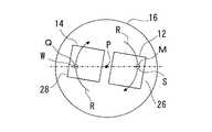
支持装置16は、図示の例では、第1の支持体26と第2の支持体28とを有する円板を用いている。第1の支持体26と第2の支持体28とは、円板状の支持装置16に支持装置16の回転軸線Pに関して対称すなわち回転対称に配置されている。少なくとも、第1の支持体26は光を透過させる透明部分とされている。
【0023】
マスク12は、第1の支持体26に図示しない第1の取り付け装置によって取り外し可能に取り付けられている。また、被露光物14は、その感光層側が上方を向くように第2の支持体28に図示しない第2の取り付け装置によって取り外し可能に取り付けられている。
【0024】
したがって、第1の支持体26に取り付けられたマスク12と第2の支持体28に取り付けられた被露光物14とは、支持装置16の回転軸線Pに関して対称すなわち回転対称に配置されている。換言すれば、マスク12と被露光物14とは、支持装置16の回転軸線Pを通る直径方向(光源光Aの指向方向)に離されて配置されている。
【0025】
上記のように、支持装置16は、円板を用い、この円板の上面にマスク12及び被露光物14のいずれをも取り付けているから、上下方向の寸法が小さい。
【0026】
回転装置18は、図示しないサーボ機構によって支持装置16を一方向に回転させる。図示の例では、回転装置18は、支持装置16を回転軸線Pの周りに時計方向Rに回転させる。
【0027】
結像光学装置22は、反射鏡30を光源装置20とマスク12との間の光路に配置し、反射鏡32、34、36をほぼM字形を形成するようにM字の3つの角の部分に配置し、結像用のレンズ38をマスク12と反射鏡32との間の光路に配置し、結像用のレンズ40を反射鏡36と被露光物14との間の光路に配置している。
【0028】
反射鏡30は、光源装置20から発した光源光をマスク12に導く(照射領域をMで示す)。反射鏡32、34、36は、反射鏡30からの光をその進行方向を順次変更して被露光物14に導く(露光領域をQで示す)。レンズ38及び40は、光源光を、マスク12のパターンが被露光物14の感光層に等倍率で転写されるように、被露光物14の感光層に結像させる。
【0029】
反射鏡34は、光学的に「しぼり」の機能を有するように大きさや形状が決められている。代わりに、反射鏡34の直前に、しぼり装置又はピンホールを有する部材を配置してもよい。
【0030】
被露光物14の感光層に導かれた光は該感光層に結像され、これにより、マスク12の照射領域の像が被露光物14の感光層に転写される。
【0031】
照射位置変更装置24は、移動装置42によって反射鏡30を光源光Aの指向方向(マスク12及び被露光物14の離間方向)に直線的に移動させ、移動装置44によって反射鏡32、36及びレンズ38、40を光源光Aの指向方向(マスク12及び被露光物14の離間方向)直線的に移動させ、また反射鏡32、36を回転させ、移動装置46によって反射鏡34を光源光Aの指向方向(マスク12及び被露光物14の離間方向)と垂直に直線的に移動させる。
【0032】
移動装置42は、モータ装置48の回転軸に結合されたねじ棒50に移動体52を螺合させている。ねじ棒50は、マスク12及び被露光物14の離間方向に伸びている。移動体52は、図示しないガイドレールに回転不能に支持され、ねじ棒50の回転によってマスク12及び被露光物14の離間方向に移動される。
【0033】
移動体52は、ねじ棒50とほぼ垂直であって支持装置16とほぼ平行に伸びる連結棒54に反射鏡30を取り付けている。したがって、反射鏡30は、マスク12への光Bの照射位置が支持装置16の半径方向の外方から内方へ又はその逆へ変位するように、マスク12及び被露光物14の離間方向に移動する。
【0034】
移動装置44は、モータ装置56の回転軸に結合されたねじ棒58に移動体62を螺合させ、ねじ棒58に結合されたねじ棒60に移動体64を螺合させている。ねじ棒58とねじ棒60とはそれらのねじの螺旋方向が反対になるように、逆ねじに形成されている。
【0035】
移動体62は、図示しないガイドレールに回転不能に支持され、ねじ棒58の回転によってマスク12及び被露光物14の離間方向に移動される。移動体62は、ねじ棒58とほぼ垂直であって支持装置16とほぼ平行に伸びる連結棒66及び68に反射鏡32及びレンズ38を取り付けている。
【0036】
したがって、反射鏡32及びレンズ38は、反射鏡30からの光を受けるようにマスク12及び被露光物14の離間方向に移動される。
【0037】
移動体62は、図示しないモータ装置を収容している。このモータ装置は、連結棒66を該連結棒の伸長方向を回転軸線として回転させることによって反射鏡32を反射鏡30からの光が反射鏡34に入射するように回転させて反射鏡32の反射面の向きを変える。
【0038】
移動体64は、図示しないガイドレールに回転不能に支持され、ねじ棒60の回転によってマスク12及び被露光物14の離間方向に移動される。移動体64は連結棒70及び72に反射鏡36及びレンズ40を取り付けている。したがって、反射鏡36及びレンズ40は、反射鏡34からの光を受けるようにマスク12及び被露光物14の離間方向に移動される。
【0039】
移動体64は、図示しないモータ装置を収容している。このモータ装置は、連結棒70を回転させることによって反射鏡36を反射鏡34からの光が反射鏡36に入射するように回転させて、反射鏡36の反射面の向きを変える。
【0040】
移動装置46は、モータ装置74の回転軸に結合されたねじ棒76に移動体78を螺合させている。
【0041】
移動体78は、図示しないガイドレールに回転不能に支持され、ねじ棒76の回転によって支持装置16の回転軸線Pとほぼ平行に上下方に移動される。移動体78は、ねじ棒76とほぼ垂直であって支持装置16とほぼ平行に伸びる連結棒80に反射鏡34を取り付けている。
【0042】
したがって、反射鏡34は、反射鏡32から光を受け、その光を反射鏡36に導くように支持装置16の回転軸線Pとほぼ平行に上下方に移動される。
【0043】
次に、図2から図4を参照して、露光装置10により光とマスク12及び被露光物14とを相対的に2次元的に移動させてマスク12のパターン全面を被露光物14に露光するいわゆる走査露光をする露光方法について説明する。
【0044】
以下の説明においては、マスク12への光Bの照射位置を支持装置16の半径方向の外方から内方へ変位させて走査する場合で説明する。
【0045】
図2及び図3(A)を参照するに、露光に先だって、マスク12と被露光物14とを支持装置16に該支持装置の回転軸線Pに対して対称すなわち回転対称に取り付けられる。
【0046】
また、マスク12への照射領域Mが、マスク12の回転軸線Pから最も遠い位置すなわち支持装置16の直径方向の外方の位置を通るように、予め反射鏡30が、移動装置42により移動され、位置決めされている。
【0047】
反射鏡32、34及び36は、マスク12からの透過光が、マスク12への照射領域Mの位置Sと支持装置16の回転軸線Pに対して対称の、被露光物14の位置Wに露光領域Qが形成されるように、移動装置44及び46により移動され、位置決めされている。
【0048】
露光においては、光源光をマスク12を経て被露光物14に導く工程と、支持装置16を回転装置18によって回転させる工程と、反射鏡30、32、34、36及びレンズ38、40を移動させかつ反射鏡32、36を回転させて被露光物14への露光位置を支持装置16の半径方向の外方から内方へ変化させることを含む工程とが同時に行われることによって、走査露光がされる。以下に、詳しく説明する。
【0049】
露光装置10の図示しない制御パネルが操作されることにより、始動信号が図示しない制御装置に入力される。始動信号を受けた制御装置は、光源装置20に発光開始信号を送る。発光開始信号を受けた光源装置20は、光源を所定時間光束の発生を継続する。光源にエキシマレーザ光を用いたときには、光源装置20は所定時間パルス光を発生する。
【0050】
図3(A)を参照するに、走査露光の初期段階において、マスク12の回転軸線Pから最も遠い位置に光源光が照射される。反射鏡30は、光源装置20から発した光束A1の少なくとも一部を反射する。反射光は、光B1として進み、マスク12に入射する。マスク12への入射光の少なくとも一部は、マスク12の光入射部が透過部分であるか否かに応じた光C1として進む。反射鏡32は、レンズ38を経た光を、その進行方向を変えて光D1として反射鏡34に導く。
【0051】
反射鏡34は、反射鏡32からの反射光D1を、その進行方向を変えて光E1として反射鏡36に導く。反射鏡36は、その進行方向を変えて、レンズ40を経て光F1として被露光物14に導く。レンズ38及び40は、マスク12からの透過光を被露光物14の感光層に結像させる。被露光物14の位置Wにおいて露光領域Qが形成される。
【0052】
光源光が上記のように被露光物14に導かれる間、支持装置16は、回転装置18によって回転軸線Pの周りに回転されている。これにより、照射領域Mは、支持装置16の回転によって支持装置16に対して支持装置16の周方向に変位する。したがって、照射領域Mは支持装置16の1回転によって再びほぼ位置Sに変位する。
【0053】
光源光がマスク12に照射されなくなった位置から再びマスク12に照射される位置に、照射領域Mが変位するまでの間に、露光装置10の図示しない制御装置は、移動装置42のモータ装置48に駆動信号を送る。駆動信号を受けたモータ装置48は、ねじ棒50を所定角度だけ回転させて、移動体52を介して反射鏡30を支持装置16とほぼ平行に回転軸線Pに向けて所定量X1(図3(A)を参照。)だけ移動させる。これによって、照射領域Mは支持装置16の回転軸線Pに近づく方向すなわち支持装置16の半径方向に外方から内方に向けて移動する。
【0054】
図4を参照するに、照射領域Mは、支持装置16の1回転毎に半径方向に外方から内方へ寸法dだけ移動して、同心円R1、R2、・・・、Rn、・・・、Reを描くように、周方向に移動しつつ、半径方向内方へ移動する。この寸法dは、RnとRn+1との間の半径方向の寸法を示し、照射領域Mの大きさや形状に依存する。
【0055】
上記のように照射領域Mが支持装置16の1回転毎に照射領域Mの走査経路の変更ピッチdだけ半径方向へ移動するように、反射鏡30が距離dだけ移動されると同時に、これと同期して、以下に詳述するように反射鏡32、34、36、レンズ38、40が移動され、反射鏡32、36が回転される。
【0056】
移動装置44のモータ装置56は、ねじ棒58を所定角度だけ回転させて、反射鏡32及びレンズ38を、移動体62を介して支持装置16とほぼ平行に回転軸線Pに向けて所定量X1(図3(A)を参照。)だけ移動させる。モータ装置56は、ねじ棒58を介してねじ棒60を所定角度だけ回転させて、反射鏡36及びレンズ40を、移動体64を介して支持装置16の回転面とほぼ平行に回転軸線Pに向けて所定量X1(図3(A)を参照。)だけ移動させる。
【0057】
移動体62内に収容されている図示しないモータ装置は、反射鏡32を、連結棒66の伸長方向を回転軸線として、連結棒66を介して図3における反時計方向にr1だけ回転させて、反射鏡32の反射面の向きを変える。移動体64内に収容されている図示しないモータ装置は、反射鏡36を、連結棒70の伸長方向を回転軸線として連結棒70を介して図3における時計方向にr1だけ回転させ、反射鏡36の反射面の向きを変える。
【0058】
移動装置46のモータ装置74は、ねじ棒76を所定角度だけ回転させて、反射鏡34を、移動体78を介して支持装置16とほぼ垂直に下方に所定量Y1(図3(A)を参照。)だけ移動させる。
【0059】
上記のように、反射鏡30の移動と同期して反射鏡32、34、36、レンズ38、40が移動され、反射鏡32、36が所定角度回転される。これによって、被露光物14への露光領域Qは、支持装置16の回転軸線Pに近づく方向すなわち支持装置16の半径方向に外方から内方に向く照射領域Mの移動量と同じだけ移動する。
【0060】
したがって、マスク12への照射領域Mと被露光物14への露光領域Qとは、支持装置16の回転軸線Pに対して常に対称すなわち回転対称の位置にある。また、マスク12と被露光物14との間の光路の長さは常に一定に維持される。
【0061】
具体的に、マスク12とレンズ38との間の光路の長さL1と、レンズ38と反射鏡34との間の光路の長さL2と、反射鏡34とレンズ40との間の光路の長さL3と、レンズ40と被露光物14との間の光路の長さL4とが互いに常に等しくなる。
【0062】
さらに、テレセントリック光学系を用いて露光倍率を1:1とした場合には、L1=L2=L3=L4=fである。ここで、fはレンズ38、40の焦点距離である。したがって、倍率を1:1とする場合には、同じ焦点距離を有するレンズ38、40が用いられる。
【0063】
以上のように、マスク12への照射領域Mと被露光物14への露光領域Qとが常に支持装置16の回転軸線Pに対して回転対称の位置にあるように維持されつつ走査露光が行われる。
【0064】
図3(B)を参照するに、走査露光の最終の段階においては、マスク12の回転軸線Pから最も近い位置に光源光が照射される。これによって、マスク12の全パターンが被露光物14に露光されて、露光が完了する。
【0065】
上記のように、本発明においては、露光の間支持装置16を一方向に回転させればよいので、従来の露光技術、例えば支持装置をXY駆動装置によってXY駆動させる露光技術の場合に生じる、支持装置の移動・停止の繰り返しに起因する問題がなく、駆動系に作用する負荷が最小限で済む。また、負荷が少なくて済むので、高速で走査することができ、スループットが大きく向上する。
【0066】
支持装置16は、マスク12への照射量が一定である場合において、支持装置16の外周側での露光時には支持装置16の回転が遅く、内周側になるにつれて回転が速くなるように、すなわち線速度が一定になるように回転される。支持装置16の回転を角速度を一定とした回転すなわち等速回転とし、その代わりに露光箇所に応じて露光量を変化させるようにしてもよい。
【0067】
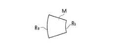
図5を参照するに、照射領域Mの形状は、曲率半径が異なる2つの円弧RB、RSで囲まれた扇形状を有するようにしてもよい。このような形状にすれば、照射領域Mの形状が円形や六角形等である場合に生じる走査時の照射領域Mの外周側(円弧RB側)と内周側(円弧RS側)との間の光量差を解消することができる。
【0068】
照射領域Mの走査経路として、図4に示す例においては同心円を描くような走査経路を示したが、回転中心に漸近的に近づく螺旋形状を描くような走査経路で走査するようにしてもよい。同心円及び螺旋のいずれの走査経路を用いる場合も、照射領域M及び露光領域Qを半径方向内方から外方へ移動させてもよい。
【0069】
結像用のレンズ38、40のそれぞれを単一のレンズとして説明したが、例えば解像度に応じて複数のレンズを用いることができる。複数のレンズとして、例えば、像の拡大倍率が1対1のテレセントリック光学系を用いることができる。
【0070】
図6に示すように、複数組のマスク及び被露光物を支持装置16に配置すれば、スループットがさらに向上する。図示の例では、マスク12及び被露光物14の組に対してマスク82及び被露光物84の組が90度だけずらして配置されている。
【0071】
図7においては、図1から図4に示す露光装置10と共通の部分については同じ符号を用いていると共に、共通部分の一部を省略している。
【0072】
図7を参照するに、露光装置86においては、図1に示す露光装置10で用いたレンズ38及び40に代えて、1つの結像用のレンズ88を用いている。レンズ88は、図示しない連結棒によって移動装置46の移動体78に取り付けられている。したがって、レンズ88は、モータ装置74の駆動によるねじ棒76の回転によって移動体78を介して反射鏡34と一体的に直線的に移動される。
【0073】
露光装置86においても、マスク12と被露光物14との間の光路の長さは常に一定に維持される。詳しくは、マスク12とレンズ88との間の光路の長さLL1と、レンズ88と被露光物14との間の光路の長さLL2とは常に等しく保たれる。
【0074】
図7に示す実施例においては、結像用のレンズが1つで済む。露光装置の構造が従来と比べてより簡単になり、装置の設計や製造が容易になる。
【0075】
図8においては、図1から図4に示す露光装置10と共通の部分については同じ符号を用いていると共に、共通部分の一部を省略している。
【0076】
図8を参照するに、露光装置90においては、図1に示す露光装置10で用いたレンズ38、40及び反射鏡34に代えて、凹面鏡92及び反射鏡94を用いる。凹面鏡92は、図示しない連結棒によって移動装置46の移動体78に取り付けられている。したがって、凹面鏡92は、モータ装置74の駆動によるねじ棒76の回転によって移動体78と一体的に直線的に移動される。反射鏡94は、移動することなく、図示しない固定側の所定の位置に取り付けられている。
【0077】
凹面鏡92は、凹面側に反射面を有し、反射鏡及び結像レンズの両方の機能を有する。反射鏡94は、反射鏡32からの反射光を凹面鏡92に導き、凹面鏡92からの反射光を反射鏡36に導く。
【0078】
露光装置90においても、マスク12と被露光物14との間の光路の長さは常に一定に維持される。詳しくは、マスク12と凹面鏡92との間の光路の長さLL3と、凹面鏡92と被露光物14との間の光路の長さLL4とは常に等しく保たれる。
【0079】
図8に示す実施例においては、結像用のレンズを用いる必要がない。したがって、多くの制約を有するレンズ設計やレンズ製造等の問題がなく、露光装置の構造が従来と比べてより簡単になり、装置の設計や製造が容易になる。
【0080】
本発明は、上記実施例に限定されず、その趣旨を逸脱しない限り、種々変更することができる。
【図面の簡単な説明】
【図1】本発明に係る露光装置の第1の実施例を示す斜視図。
【図2】図1に示す露光装置の支持装置を示す平面図。
【図3】図1に示す露光装置の作動を示す側面図。
【図4】図1に示す露光装置の作動を示す平面図。
【図5】本発明に係る露光装置に用いる照射領域の例を示す平面図。
【図6】本発明に係る露光装置の支持装置の例を示す平面図。
【図7】本発明に係る露光装置の第2の実施例を示す側面図。
【図8】本発明に係る露光装置の第3の実施例を示す側面図。
【符号の説明】
10、86、90 露光装置
12、82 マスク
14、84 被露光物
16 支持装置
18 回転装置
20 光源装置
22 結像光学装置
24 照射位置変更装置
26、28 支持体
30、32、34、36、94 反射鏡
38、40、88 レンズ
42、44、46 移動装置
48、56、74 モータ装置
52、62、64、78 移動体
54、66、68、70、72、80 連結棒
92 凹面鏡[0001]
BACKGROUND OF THE INVENTION
The present invention relates to an exposure method and apparatus for exposing a pattern of an exposure mask (hereinafter referred to as “mask”) onto a photosensitive material, and in particular, a photolithography process in manufacturing a semiconductor integrated circuit, a liquid crystal display device, a flexible printed circuit board, and the like. The present invention relates to an exposure method and apparatus suitable as an exposure technique used in the above-mentioned techniques and as an exposure technique used in a printing plate making scanner device, an electronic copying machine, and the like.
[0002]
[Prior art]
For example, there is a projection exposure apparatus that exposes a mask pattern onto a photosensitive material using an imaging optical system as an exposure apparatus used in a photolithography process that is one of the manufacturing processes of a semiconductor integrated circuit, a liquid crystal display device, and the like.
[0003]
As one of such exposure apparatuses, for example, a mask and an object to be exposed having a photosensitive material are supported on the same stage so that their respective light incident surfaces are substantially the same plane, and the light from the exposure light source is masked. There is a projection exposure apparatus in which light transmitted through a mask is incident on a photosensitive material by an imaging optical system (for example, US Pat. No. 5,652,645).
[0004]
This projection exposure apparatus performs so-called scanning exposure in which a mask and a support device that supports an object to be exposed and an optical system are relatively two-dimensionally moved. Specifically, this exposure apparatus uses an XY drive device to move the support device in the XY plane. In exposure, the support device moves in one direction, stops, and moves by the scanning pitch of the irradiation area. And the movement in the reverse direction is repeated several times.
[0005]
[Problems to be solved by the invention]
However, in this projection exposure apparatus, the XY drive device must operate the support device so as to control the movement of the support device each time the support device moves and stops as described above. In particular, in order to drive the support device at a high speed by the XY drive device, a device for eliminating or alleviating the physical load on the XY drive device due to the weight and inertia of the support device is required, and the exposure apparatus is large. There was a drawback of becoming.
[0006]
In addition, when a mask having a large dimension or a support device that supports an object to be exposed is used, the weight of the support device increases, the inertia of the support device increases, and the physical load acting on the XY drive device further increases. Increase. As a result, for example, the influence of backlash or the like on the movement amount accuracy cannot be ignored, and the durability of the XY drive device is lowered.
[0007]
On the other hand, as one of exposure apparatuses that do not use such an XY driving apparatus, there is an exposure apparatus that performs scanning exposure by continuously rotating a mask and an object to be exposed (for example, JP-A-6-274945). However, in this exposure apparatus, since the mask and the object to be exposed arranged with the projection optical system interposed therebetween are rotated by separate driving devices, the alignment between the mask and the object to be exposed is not easy. Various problems such as the need for accurate synchronization between the apparatuses and the need to remove the eccentricity in the rotation of the mask and the object to be exposed have resulted in the disadvantage that the drive mechanism becomes complicated.
[0008]
An object of the present invention is to reduce a physical load applied to a drive mechanism for moving a support device that supports a mask and an object to be exposed having a photosensitive material, and to make the drive mechanism a simple structure.
[0009]
[Solution means, actions and effects for solving the problems]
According to the present invention, a method of exposing a pattern of an exposure mask to a photosensitive material includes an incident step of causing at least a part of light from an exposure light source to enter the mask supported by a support device; An imaging step of causing the transmitted light to be incident on the photosensitive material supported by the support device from a direction different from the light incident direction on the mask to form an image of the transmitted light on the photosensitive material; A rotation step of rotating the support device so that the irradiation position of the light on the mask changes in the circumferential direction, and the irradiation position of the light on the mask and the photosensitive material during the rotation of the support device within the rotation plane; And an irradiation position changing step of changing in a direction different from the circumferential direction.
[0010]
According to the present invention, an apparatus for exposing a pattern of an exposure mask onto a photosensitive material includes a first support portion that supports the mask so that the mask receives at least part of light from an exposure light source, and the photosensitive device. A support device comprising: a second support portion for supporting the material such that the photosensitive material receives light transmitted from the mask from a direction different from the light incident direction to the mask; and the transmitted light from the mask An imaging optical device that guides the photosensitive material to form an image, a rotating device that rotates the support device so that the irradiation position of the light from the light source to the mask changes in the circumferential direction, the mask, and the photosensitive material And an irradiation position changing device that changes the irradiation position of the light in a direction different from the circumferential direction within the rotation plane of the support device.
[0011]
The support device that supports the mask and the photosensitive material is rotated by a rotating device, whereby the irradiation position of the light source light on the mask and the irradiation position of the transmitted light on the photosensitive material change in the circumferential direction. Further, the irradiation position changing device changes the irradiation position of the light source light onto the mask and the irradiation position of the light onto the photosensitive material in a direction different from the circumferential direction within the rotation surface of the support device.
[0012]
Therefore, according to the invention, the support device need only always be rotated continuously, for example in one direction, by means of a rotating device. As a result, the physical load applied to the drive mechanism for moving the support device is reduced, and scanning exposure at a higher speed is possible and throughput is improved as compared with scanning exposure using a conventional XY drive mechanism. .
[0013]
The transmitted light from the mask is passed through a plurality of reflecting mirrors and at least one imaging lens to change the traveling direction of the transmitted light from the mask and to form an image on the photosensitive material, and to move at least one of the reflecting mirrors You may let them.
[0014]
The reflecting mirror may move the reflecting mirror in the direction of the rotation axis of the support device. Further, the imaging lens may be moved together with the reflecting mirror.
[0015]
The transmitted light from the mask may be passed through a plurality of reflecting mirrors and at least one concave mirror to change the traveling direction of the transmitted light from the mask, to form an image on the photosensitive material, and to move the concave mirror. In this case, the concave mirror may be moved in the direction of the rotation axis of the support device.
[0016]
The mask and the photosensitive material may be arranged symmetrically with respect to the rotation axis of the support device.
[0017]
The irradiation position may be changed while maintaining the length of the optical path between the mask and the photosensitive material constant.
[0018]
DETAILED DESCRIPTION OF THE INVENTION
Referring to FIGS. 1 and 2, the
[0019]
The
[0020]
As the
[0021]
As the object to be exposed 14, for example, an object to be exposed in which a photosensitive layer is formed of a photosensitive material on one surface of a plate-like substrate can be used. In FIG. 1, the object to be exposed 14 has substantially the same size and shape as the
[0022]
In the illustrated example, the
[0023]
The
[0024]
Therefore, the
[0025]
As described above, since the
[0026]
The
[0027]
In the imaging
[0028]
The reflecting
[0029]
The size and shape of the reflecting
[0030]
The light guided to the photosensitive layer of the object to be exposed 14 forms an image on the photosensitive layer, whereby the image of the irradiation area of the
[0031]
The irradiation
[0032]
In the moving
[0033]
The moving
[0034]
In the moving
[0035]
The moving
[0036]
Therefore, the reflecting
[0037]
The moving
[0038]
The moving
[0039]
The moving
[0040]
In the moving
[0041]
The
[0042]
Therefore, the reflecting
[0043]
Next, referring to FIGS. 2 to 4, the
[0044]
In the following description, a case where scanning is performed by displacing the irradiation position of the light B onto the
[0045]
Referring to FIGS. 2 and 3A, prior to exposure, the
[0046]
In addition, the reflecting
[0047]
The reflecting mirrors 32, 34, and 36 are exposed at a position W of the
[0048]
In the exposure, the step of guiding the light source light to the
[0049]
When a control panel (not shown) of the
[0050]
Referring to FIG. 3A, light source light is irradiated to a position farthest from the rotation axis P of the
[0051]
The reflecting
[0052]
While the light source light is guided to the
[0053]
The control device (not shown) of the
[0054]
Referring to FIG. 4, the irradiation region M moves by a dimension d from the outside to the inside in the radial direction for each rotation of the
[0055]
As described above, the reflecting
[0056]
The
[0057]
The motor device (not shown) accommodated in the moving
[0058]
The
[0059]
As described above, the reflecting mirrors 32, 34, 36 and the
[0060]
Therefore, the irradiation area M to the
[0061]
Specifically, the length L of the optical path between the
[0062]
Further, when the exposure magnification is 1: 1 using a telecentric optical system, L1 = L2 = L3 = L4 = F. Here, f is the focal length of the
[0063]
As described above, the scanning exposure is performed while the irradiation region M to the
[0064]
Referring to FIG. 3B, in the final stage of the scanning exposure, the light source light is irradiated to the position closest to the rotation axis P of the
[0065]
As described above, in the present invention, it is only necessary to rotate the
[0066]
The
[0067]
Referring to FIG. 5, the shape of the irradiation region M is two arcs R having different radii of curvature.B , RS You may make it have the fan shape enclosed by. With such a shape, the outer peripheral side of the irradiation region M during scanning (arc R) that occurs when the shape of the irradiation region M is circular, hexagonal, or the like.B Side) and inner circumference side (arc R)S The difference in the amount of light can be eliminated.
[0068]
In the example shown in FIG. 4, a scanning path that draws a concentric circle is shown as the scanning path of the irradiation region M. However, scanning may be performed using a scanning path that draws a spiral shape asymptotically approaching the center of rotation. . In either case of using concentric or spiral scanning paths, the irradiation region M and the exposure region Q may be moved from the inside in the radial direction to the outside.
[0069]
Although each of the
[0070]
As shown in FIG. 6, if a plurality of sets of masks and objects to be exposed are arranged on the
[0071]
In FIG. 7, the same reference numerals are used for parts common to the
[0072]
Referring to FIG. 7, the
[0073]
Also in the
[0074]
In the embodiment shown in FIG. 7, only one imaging lens is required. The structure of the exposure apparatus becomes simpler than the conventional one, and the design and manufacture of the apparatus become easy.
[0075]
In FIG. 8, the same reference numerals are used for portions common to the
[0076]
Referring to FIG. 8, in the
[0077]
The
[0078]
Also in the
[0079]
In the embodiment shown in FIG. 8, it is not necessary to use an imaging lens. Therefore, there are no problems such as lens design and lens manufacturing having many restrictions, the structure of the exposure apparatus becomes simpler than the conventional one, and the design and manufacture of the apparatus becomes easy.
[0080]
The present invention is not limited to the above embodiments, and various modifications can be made without departing from the spirit of the present invention.
[Brief description of the drawings]
FIG. 1 is a perspective view showing a first embodiment of an exposure apparatus according to the present invention.
2 is a plan view showing a support device for the exposure apparatus shown in FIG. 1. FIG.
3 is a side view showing the operation of the exposure apparatus shown in FIG. 1. FIG.
4 is a plan view showing the operation of the exposure apparatus shown in FIG. 1. FIG.
FIG. 5 is a plan view showing an example of an irradiation region used in the exposure apparatus according to the present invention.
FIG. 6 is a plan view showing an example of a support device of the exposure apparatus according to the present invention.
FIG. 7 is a side view showing a second embodiment of the exposure apparatus according to the present invention.
FIG. 8 is a side view showing a third embodiment of the exposure apparatus according to the present invention.
[Explanation of symbols]
10, 86, 90 Exposure apparatus
12, 82 mask
14, 84 Exposed object
16 Support device
18 Rotating device
20 Light source device
22 Imaging optical device
24 Irradiation position change device
26, 28 Support
30, 32, 34, 36, 94 Reflector
38, 40, 88 lenses
42, 44, 46 Mobile device
48, 56, 74 Motor device
52, 62, 64, 78 Mobile
54, 66, 68, 70, 72, 80 Connecting rod
92 Concave mirror
Claims (16)
Translated fromJapanese露光用光源からの光の少なくとも一部を、支持装置に支持された前記マスクに入射させる入射ステップと、
前記マスクからの透過光を、前記支持装置に支持された前記感光材に前記マスクへの光入射方向とは異なる方向から入射させて前記透過光を前記感光材に結像させる結像ステップと、
前記光源からの光の前記マスクへの照射位置が周方向に変化するように前記支持装置を回転させる回転ステップと、
前記支持装置の回転中に前記マスク及び前記感光材への光の照射位置を前記回転面内で前記周方向とは異なる方向に変化させる照射位置変更ステップとを含む、露光方法。A method of exposing a pattern of an exposure mask to a photosensitive material,
An incident step of causing at least a part of light from the exposure light source to enter the mask supported by a support device;
An imaging step of causing the transmitted light from the mask to enter the photosensitive material supported by the support device from a direction different from the light incident direction to the mask to form an image of the transmitted light on the photosensitive material;
A rotation step of rotating the support device so that the irradiation position of the light from the light source to the mask changes in the circumferential direction;
An exposure position changing step of changing an irradiation position of light to the mask and the photosensitive material in a direction different from the circumferential direction in the rotation surface during rotation of the support device.
前記照射位置変更ステップは、少なくとも1つの前記反射鏡を移動させることを含む、請求項1に記載の方法。The imaging step includes passing the transmitted light from the mask through a plurality of reflecting mirrors and at least one imaging lens to change the traveling direction of the transmitted light from the mask and forming an image on the photosensitive material. ,
The method according to claim 1, wherein the irradiation position changing step includes moving at least one of the reflecting mirrors.
前記照射位置変更ステップは、前記凹面鏡を移動させることを含む、請求項1に記載の方法。The imaging step includes passing the light transmitted from the mask through a plurality of reflecting mirrors and at least one concave mirror to change the traveling direction of the transmitted light from the mask and forming an image on the photosensitive material,
The method according to claim 1, wherein the irradiation position changing step includes moving the concave mirror.
前記マスクを該マスクが露光用光源からの光の少なくとも一部を受けるように支持する第1の支持部と、前記感光材を該感光材が前記マスクからの透過光を前記マスクへの光入射方向とは異なる方向から受けるように支持する第2の支持部とを備える支持装置と、
前記マスクからの透過光を前記感光材に結像させるべく導く結像光学装置と、
前記光源からの光の前記マスクへの照射位置が周方向に変化するように前記支持装置を回転させる回転装置と、
前記マスク及び前記感光材への光の照射位置を前記支持装置の回転面内で前記周方向とは異なる方向に変化させる照射位置変更装置とを含む、露光装置。An apparatus for exposing a pattern of an exposure mask to a photosensitive material,
A first support portion for supporting the mask so that the mask receives at least part of light from an exposure light source; and the photosensitive material that receives light transmitted from the mask to the mask. A support device comprising a second support portion that supports the receiving device so as to receive from a direction different from the direction;
An imaging optical device for guiding the transmitted light from the mask to form an image on the photosensitive material;
A rotating device that rotates the support device so that the irradiation position of the light from the light source to the mask changes in the circumferential direction;
An exposure apparatus comprising: an irradiation position changing device that changes an irradiation position of light to the mask and the photosensitive material in a direction different from the circumferential direction within a rotation plane of the support device.
Priority Applications (5)
| Application Number | Priority Date | Filing Date | Title |
|---|---|---|---|
| JP2002177098AJP4146673B2 (en) | 2002-06-18 | 2002-06-18 | Exposure method and apparatus |
| TW092100665ATWI226518B (en) | 2002-06-18 | 2003-01-14 | Exposure method and apparatus |
| KR10-2003-0004636AKR100510198B1 (en) | 2002-06-18 | 2003-01-23 | Exposure Method and Apparatus |
| CNB031104169ACN1249527C (en) | 2002-06-18 | 2003-04-09 | Method and apparatus for exposure |
| US10/458,387US6816231B2 (en) | 2002-06-18 | 2003-06-09 | Method and apparatus for exposure |
Applications Claiming Priority (1)
| Application Number | Priority Date | Filing Date | Title |
|---|---|---|---|
| JP2002177098AJP4146673B2 (en) | 2002-06-18 | 2002-06-18 | Exposure method and apparatus |
Publications (2)
| Publication Number | Publication Date |
|---|---|
| JP2004022880A JP2004022880A (en) | 2004-01-22 |
| JP4146673B2true JP4146673B2 (en) | 2008-09-10 |
Family
ID=29728139
Family Applications (1)
| Application Number | Title | Priority Date | Filing Date |
|---|---|---|---|
| JP2002177098AExpired - Fee RelatedJP4146673B2 (en) | 2002-06-18 | 2002-06-18 | Exposure method and apparatus |
Country Status (5)
| Country | Link |
|---|---|
| US (1) | US6816231B2 (en) |
| JP (1) | JP4146673B2 (en) |
| KR (1) | KR100510198B1 (en) |
| CN (1) | CN1249527C (en) |
| TW (1) | TWI226518B (en) |
Families Citing this family (10)
| Publication number | Priority date | Publication date | Assignee | Title |
|---|---|---|---|---|
| US6563581B1 (en)* | 2000-07-14 | 2003-05-13 | Applera Corporation | Scanning system and method for scanning a plurality of samples |
| JP5218049B2 (en)* | 2006-05-31 | 2013-06-26 | 株式会社ニコン | Exposure apparatus and exposure method |
| WO2009088003A1 (en)* | 2008-01-10 | 2009-07-16 | Nikon Corporation | Exposure method, exposure device, and device manufacturing method |
| US20090303454A1 (en)* | 2008-06-10 | 2009-12-10 | Nikon Corporation | Exposure apparatus with a scanning illumination beam |
| CN102414623A (en)* | 2009-04-27 | 2012-04-11 | Asml荷兰有限公司 | Lithographic apparatus and method |
| US8355116B2 (en)* | 2009-06-19 | 2013-01-15 | Nikon Corporation | Exposure apparatus and device manufacturing method |
| US8294878B2 (en)* | 2009-06-19 | 2012-10-23 | Nikon Corporation | Exposure apparatus and device manufacturing method |
| KR101215094B1 (en) | 2010-10-25 | 2012-12-24 | 삼성전자주식회사 | Work piece alignment device |
| CN109426086A (en)* | 2017-08-25 | 2019-03-05 | 富士迈半导体精密工业(上海)有限公司 | Reflective exposure sources |
| CN110426923A (en)* | 2019-07-31 | 2019-11-08 | 江苏盟星智能科技有限公司 | A kind of helical scan type laser explosure equipment and its method of operation |
- 2002
- 2002-06-18JPJP2002177098Apatent/JP4146673B2/ennot_activeExpired - Fee Related
- 2003
- 2003-01-14TWTW092100665Apatent/TWI226518B/enactive
- 2003-01-23KRKR10-2003-0004636Apatent/KR100510198B1/ennot_activeExpired - Fee Related
- 2003-04-09CNCNB031104169Apatent/CN1249527C/ennot_activeExpired - Fee Related
- 2003-06-09USUS10/458,387patent/US6816231B2/ennot_activeExpired - Fee Related
Also Published As
| Publication number | Publication date |
|---|---|
| CN1467568A (en) | 2004-01-14 |
| CN1249527C (en) | 2006-04-05 |
| US20030231290A1 (en) | 2003-12-18 |
| TWI226518B (en) | 2005-01-11 |
| JP2004022880A (en) | 2004-01-22 |
| KR100510198B1 (en) | 2005-08-26 |
| US6816231B2 (en) | 2004-11-09 |
| TW200400419A (en) | 2004-01-01 |
| KR20040002426A (en) | 2004-01-07 |
Similar Documents
| Publication | Publication Date | Title |
|---|---|---|
| JP4146673B2 (en) | Exposure method and apparatus | |
| JP5282895B2 (en) | Exposure apparatus, exposure method, and device manufacturing method | |
| JP3231241B2 (en) | X-ray reduction exposure apparatus and semiconductor manufacturing method using the apparatus | |
| JP2012530367A (en) | Lithographic apparatus and method | |
| JP2926325B2 (en) | Scanning exposure method | |
| JP5002009B2 (en) | Optical device | |
| JP4064676B2 (en) | Exposure apparatus and exposure method | |
| JP4387975B2 (en) | Lithographic apparatus and device manufacturing method | |
| JP2009521108A (en) | SLM direct drawing device | |
| KR100490342B1 (en) | Exposure Method and Apparatus | |
| JPH03283420A (en) | Microscopic pattern transferring method and device | |
| JP2006019510A (en) | Aligner and fabrication process of microdevice | |
| JP4376227B2 (en) | Projection apparatus for lithographic apparatus | |
| TW201945854A (en) | Projection exposure device including an illumination optical system and a shading means | |
| JPH0653113A (en) | Scanning projection exposure system | |
| US7349065B2 (en) | Exposure apparatus and device fabrication method | |
| JP2674579B2 (en) | Scanning exposure apparatus and scanning exposure method | |
| JP3161430B2 (en) | Scanning exposure method, scanning exposure apparatus, and element manufacturing method | |
| JP2010212386A (en) | Periphery exposure method, periphery exposure device, and method of manufacturing device | |
| JP2670984B2 (en) | Device manufacturing method | |
| JP2010114344A (en) | Exposure device and method of manufacturing device | |
| JPH09180991A (en) | Aligner | |
| JP2830869B2 (en) | Circuit element manufacturing method | |
| JPH11342486A (en) | Aperture mask, photo-processing method, and its device | |
| JP3123526B2 (en) | Scanning exposure apparatus and element manufacturing method using the apparatus |
Legal Events
| Date | Code | Title | Description |
|---|---|---|---|
| A621 | Written request for application examination | Free format text:JAPANESE INTERMEDIATE CODE: A621 Effective date:20050420 | |
| A977 | Report on retrieval | Free format text:JAPANESE INTERMEDIATE CODE: A971007 Effective date:20070402 | |
| TRDD | Decision of grant or rejection written | ||
| A01 | Written decision to grant a patent or to grant a registration (utility model) | Free format text:JAPANESE INTERMEDIATE CODE: A01 Effective date:20080527 | |
| A01 | Written decision to grant a patent or to grant a registration (utility model) | Free format text:JAPANESE INTERMEDIATE CODE: A01 | |
| A61 | First payment of annual fees (during grant procedure) | Free format text:JAPANESE INTERMEDIATE CODE: A61 Effective date:20080620 | |
| R150 | Certificate of patent or registration of utility model | Free format text:JAPANESE INTERMEDIATE CODE: R150 | |
| FPAY | Renewal fee payment (event date is renewal date of database) | Free format text:PAYMENT UNTIL: 20110627 Year of fee payment:3 | |
| LAPS | Cancellation because of no payment of annual fees |